
DGTk: A Data Generation Toolkit - IIIT...
80
DGTk: A Data Generation Toolkit A Thesis submitted in partial fulfillment of the requirements for the degree of Master of Science (by Research) in Computer Science by V.Vamsi Krishna 200407020 [email protected] International Institute of Information Technology Hyderabad, INDIA AUGUST 2006
Transcript of DGTk: A Data Generation Toolkit - IIIT...

DGTk: A Data Generation Toolkit
A Thesis submitted in partial fulfillment of therequirements for the degree of
Master of Science (by Research)in
Computer Science
by
V.Vamsi Krishna200407020
International Institute of Information TechnologyHyderabad, INDIA
AUGUST 2006

Copyright c© V.Vamsi Krishna, 2006
All Rights Reserved
INTERNATIONAL INSTITUTE OF INFORMATION TECHNOLOGYHyderabad, India
CERTIFICATE
It is certified that the work contained in this thesis, titled “DGTk: A Data Generation Toolkit” byV.Vamsi Krishna, has been carried out under my supervision and is not submitted elsewhere for a degree.
Date Adviser: Dr. P.J. Narayanan

To Mom, Dad and Sis

Acknowledgments
I would like to thank my supervisor Dr. P.J. Narayanan for his support and guidance through the pastfive years. I am thankful to him for introducing me to the world of computer graphics. I would like tothank my parents for their support and motivation.
Last but not the least, I would like to thank all the members of the Center for Visual Information Tech-nology (CVIT) for their support and company.
v

Abstract
Computer Vision (CV) mainly focuses on analyzing images or video streams to find objects or eventsof interest. Over the last few years very high quality algorithms have been developed in this area due tothe advances in the fields of Machine Learning, Image Processing and Pattern recognition techniques.Image Based rendering (IBR) algorithms deal with rendering novel views of a scene at photo realisticquality, given few views of the scene along with some additional information about the 3D structure ofthe scene. There has been a dramatic increase in the quality IBR algorithms developed due to the multifold increase in the processing power (both on CPU and GPU).
Both Image Based rendering and Computer Vision algorithms require accurate and high quality datafor experimentation, tuning, and testing. Traditionally research groups created datasets for this pur-pose. The datasets so developed have become standard testbeds for comparing the performance of CVand IBR algorithms. As more and more high quality algorithms began to be developed, most of suchdatasets have become obsolete and lack the ability to differentiate the performance of these algorithms.To overcome this problem, researchers create synthetic datasets which give a good indication of thealgorithm’s performance on the real world images. Due to the inherent advantages of ground truth datasuch as repeatability and ease of creation, it has become a very important part of the CV and IBR al-gorithm development. Many research groups have developed special tools for generating datasets forfingerprint recognition, skeleton extraction, etc. Such tools are very successful in generating specificdata but cannot be extended easily to support other data types. It would be helpful for the researchers tohave a simple open source tool which is easily extend able to support various input/output formats.
In this thesis, we preset DGTk a tool for generating a variety of outputs. Our tool is versatile, supportsvarious input/output formats, enables users to generate high quality, high resolution images and is veryeasy to use. Our tool supports most commonly used 3D file formats used in the research community in-cluding 3DS, MD2, AC3D and POV-ray. Unlike previous tools, our tool supports a variety of data types.These include depth maps, images at various resolutions, LDI, Object-maps and Alpha-maps. DGTkalso can generate dynamic scenes with all these properties using a key frame animation paradigm. Ourtool meets the high quality requirement of CV and IBR algorithms by providing support for ray tracing.Any scene setup in our tool can be exported to povray scene. This enables users to generate photo real-istic images when ever required. Our tool has been carefully designed to be easily extendable to support
vi

vii
other representations of data. Our tool can generate Object-maps and Alpha-maps of any scene setup inour tool. For the first time, our tool provides both Object-maps and Alpha-maps as standard data. Thisinformation is very critical for testing matting algorithms.
The goal of our work is not just to create synthetic data, but to provide a platform for data set creation.We wish to make sharing of datasets possible and make data generation a lot easier than before. Tomeet these goals, we have released our tool in the Open Source. We also released a dataset for standardapplications.
Contents
Chapter Page
1 Introduction . . . . . . . . . . . . . . . . . . . . . . . . . . . . . . . . . . . . . . . . . . 11.1 Motivation . . . . . . . . . . . . . . . . . . . . . . . . . . . . . . . . . . . . . . . . . 21.2 Major Approaches . . . . . . . . . . . . . . . . . . . . . . . . . . . . . . . . . . . . 31.3 Objectives . . . . . . . . . . . . . . . . . . . . . . . . . . . . . . . . . . . . . . . . . 4
1.3.1 Versatility . . . . . . . . . . . . . . . . . . . . . . . . . . . . . . . . . . . . . 41.3.2 High Quality . . . . . . . . . . . . . . . . . . . . . . . . . . . . . . . . . . . 41.3.3 Flexibility . . . . . . . . . . . . . . . . . . . . . . . . . . . . . . . . . . . . . 4
1.4 Contributions of the Thesis . . . . . . . . . . . . . . . . . . . . . . . . . . . . . . . . 51.5 Organization of the Thesis . . . . . . . . . . . . . . . . . . . . . . . . . . . . . . . . 7
2 Related work . . . . . . . . . . . . . . . . . . . . . . . . . . . . . . . . . . . . . . . . . . 82.1 Data Acquisition using High-Resolution Equipment . . . . . . . . . . . . . . . . . . . 82.2 Extending existing Tools for Data Acquisition . . . . . . . . . . . . . . . . . . . . . . 9
2.2.1 Blender review . . . . . . . . . . . . . . . . . . . . . . . . . . . . . . . . . . 102.2.2 3DSMax review . . . . . . . . . . . . . . . . . . . . . . . . . . . . . . . . . 11
2.3 Data Generation Tools for Specific Data . . . . . . . . . . . . . . . . . . . . . . . . . 122.4 Summary . . . . . . . . . . . . . . . . . . . . . . . . . . . . . . . . . . . . . . . . . 13
3 DGTk: Design . . . . . . . . . . . . . . . . . . . . . . . . . . . . . . . . . . . . . . . . . 143.1 Design Details . . . . . . . . . . . . . . . . . . . . . . . . . . . . . . . . . . . . . . . 143.2 Class Hierarchy for Input Objects . . . . . . . . . . . . . . . . . . . . . . . . . . . . 153.3 Output Class Hierarchy . . . . . . . . . . . . . . . . . . . . . . . . . . . . . . . . . . 173.4 GUI Class Hierarchy . . . . . . . . . . . . . . . . . . . . . . . . . . . . . . . . . . . 18
3.4.1 The Main Window . . . . . . . . . . . . . . . . . . . . . . . . . . . . . . . . 183.4.2 The TimeLineWidget . . . . . . . . . . . . . . . . . . . . . . . . . . . . . . . 193.4.3 The GLWidget . . . . . . . . . . . . . . . . . . . . . . . . . . . . . . . . . . 213.4.4 The Configuration Widgets . . . . . . . . . . . . . . . . . . . . . . . . . . . . 213.4.5 The RenderConfig Widget . . . . . . . . . . . . . . . . . . . . . . . . . . . . 223.4.6 The Tiled Renderer . . . . . . . . . . . . . . . . . . . . . . . . . . . . . . . . 22
3.5 Extensibility . . . . . . . . . . . . . . . . . . . . . . . . . . . . . . . . . . . . . . . . 223.6 Discussion . . . . . . . . . . . . . . . . . . . . . . . . . . . . . . . . . . . . . . . . . 23
4 DGTk: Different Formats and Implementation . . . . . . . . . . . . . . . . . . . . . . . . . 244.1 Arbitrarily High Resolution . . . . . . . . . . . . . . . . . . . . . . . . . . . . . . . . 24
4.1.1 Implementation . . . . . . . . . . . . . . . . . . . . . . . . . . . . . . . . . . 25
viii
CONTENTS ix
4.1.2 Validation . . . . . . . . . . . . . . . . . . . . . . . . . . . . . . . . . . . . . 284.2 High Quality . . . . . . . . . . . . . . . . . . . . . . . . . . . . . . . . . . . . . . . 29
4.2.1 Implementation . . . . . . . . . . . . . . . . . . . . . . . . . . . . . . . . . . 304.3 Camera Calibration . . . . . . . . . . . . . . . . . . . . . . . . . . . . . . . . . . . . 31
4.3.1 Implementation . . . . . . . . . . . . . . . . . . . . . . . . . . . . . . . . . . 324.4 Depth Maps . . . . . . . . . . . . . . . . . . . . . . . . . . . . . . . . . . . . . . . . 334.5 Layer Depth Images . . . . . . . . . . . . . . . . . . . . . . . . . . . . . . . . . . . . 354.6 Object Maps . . . . . . . . . . . . . . . . . . . . . . . . . . . . . . . . . . . . . . . . 364.7 Alpha Maps . . . . . . . . . . . . . . . . . . . . . . . . . . . . . . . . . . . . . . . . 37
4.7.1 Implementation . . . . . . . . . . . . . . . . . . . . . . . . . . . . . . . . . . 394.7.2 Example . . . . . . . . . . . . . . . . . . . . . . . . . . . . . . . . . . . . . 40
4.8 Pixel Correspondence . . . . . . . . . . . . . . . . . . . . . . . . . . . . . . . . . . . 404.9 Dynamic Scenes . . . . . . . . . . . . . . . . . . . . . . . . . . . . . . . . . . . . . . 434.10 Ease of Use . . . . . . . . . . . . . . . . . . . . . . . . . . . . . . . . . . . . . . . . 44
5 Results . . . . . . . . . . . . . . . . . . . . . . . . . . . . . . . . . . . . . . . . . . . . . 48
6 Conclusions and Future Work . . . . . . . . . . . . . . . . . . . . . . . . . . . . . . . . . 536.1 Future Work . . . . . . . . . . . . . . . . . . . . . . . . . . . . . . . . . . . . . . . . 536.2 Conclusions . . . . . . . . . . . . . . . . . . . . . . . . . . . . . . . . . . . . . . . . 546.3 Summary . . . . . . . . . . . . . . . . . . . . . . . . . . . . . . . . . . . . . . . . . 54
Appendix A: User Manual . . . . . . . . . . . . . . . . . . . . . . . . . . . . . . . . . . . 55A.1 Main Window . . . . . . . . . . . . . . . . . . . . . . . . . . . . . . . . . . . . . . . 55
A.1.1 File Menu . . . . . . . . . . . . . . . . . . . . . . . . . . . . . . . . . . . . . 56A.1.2 Edit Menu . . . . . . . . . . . . . . . . . . . . . . . . . . . . . . . . . . . . 56A.1.3 Tools Menu . . . . . . . . . . . . . . . . . . . . . . . . . . . . . . . . . . . . 56A.1.4 Tool Bar . . . . . . . . . . . . . . . . . . . . . . . . . . . . . . . . . . . . . 58
A.2 Creating a Static Scene . . . . . . . . . . . . . . . . . . . . . . . . . . . . . . . . . . 58A.3 Creating a Dynamic Scene . . . . . . . . . . . . . . . . . . . . . . . . . . . . . . . . 59
Appendix B: Scene File Format . . . . . . . . . . . . . . . . . . . . . . . . . . . . . . . . . 60B.1 Introduction . . . . . . . . . . . . . . . . . . . . . . . . . . . . . . . . . . . . . . . . 60B.2 Design . . . . . . . . . . . . . . . . . . . . . . . . . . . . . . . . . . . . . . . . . . . 61B.3 Implementation . . . . . . . . . . . . . . . . . . . . . . . . . . . . . . . . . . . . . . 62
Bibliography . . . . . . . . . . . . . . . . . . . . . . . . . . . . . . . . . . . . . . . . . . . . 66

List of Figures
Figure Page
1.1 Some scenes made using our tool. (a) Rendered using our tool’s internal renderer. (b)Rendered using povray from the scene description generated by our tool. . . . . . . . . 5
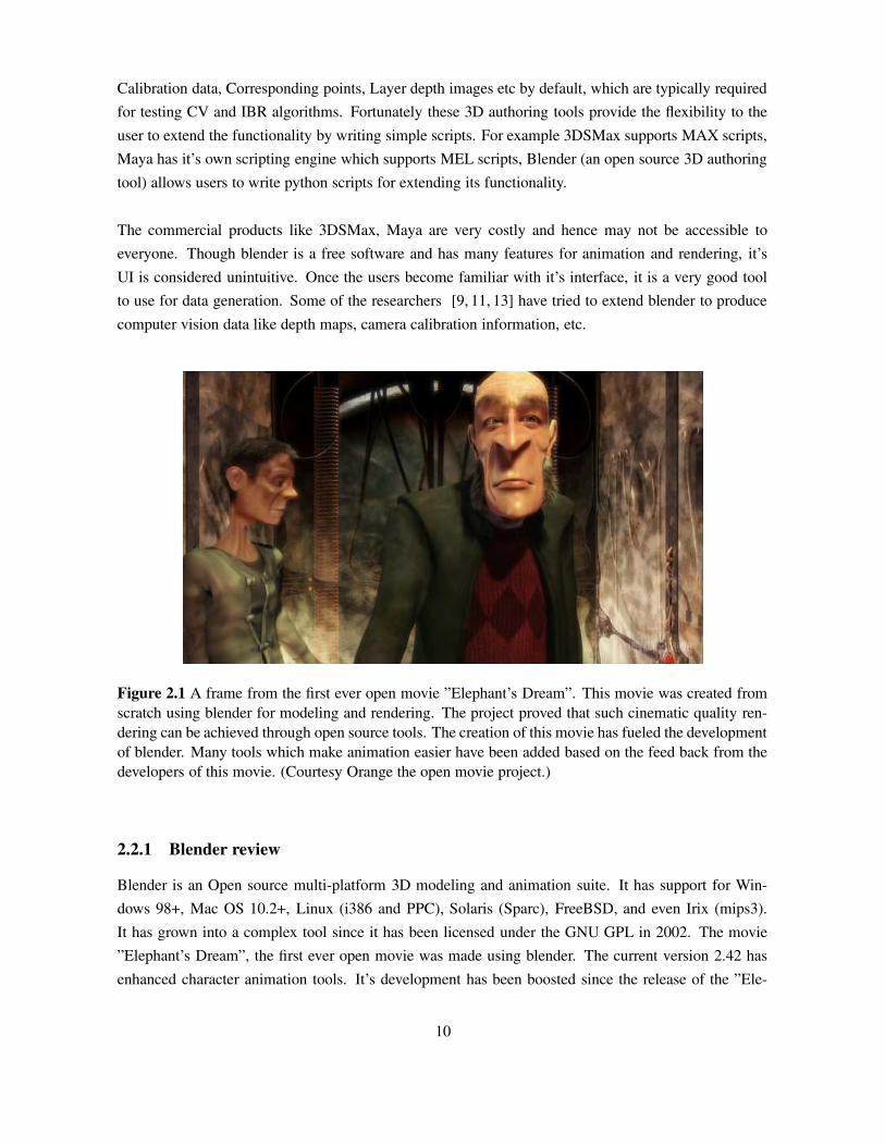
2.1 A frame from the first ever open movie ”Elephant’s Dream”. This movie was createdfrom scratch using blender for modeling and rendering. The project proved that suchcinematic quality rendering can be achieved through open source tools. The creationof this movie has fueled the development of blender. Many tools which make anima-tion easier have been added based on the feed back from the developers of this movie.(Courtesy Orange the open movie project.) . . . . . . . . . . . . . . . . . . . . . . . . 10
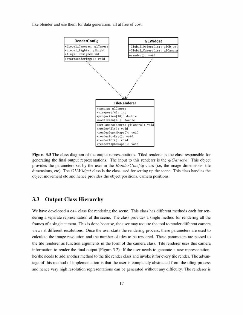
3.1 Screen Shot of the Tool . . . . . . . . . . . . . . . . . . . . . . . . . . . . . . . . . . 143.2 Class diagram of the toolkit . . . . . . . . . . . . . . . . . . . . . . . . . . . . . . . . 163.3 The class diagram of the output representations. Tiled renderer is the class respon-
sible for generating the final output representations. The input to this renderer is theglCamera. This object provides the parameters set by the user in the RenderConfig
class (i.e, the image dimensions, tile dimensions, etc). The GLWidget class is the classused for setting up the scene. This class handles the object movement etc and henceprovides the object positions, camera positions. . . . . . . . . . . . . . . . . . . . . . 17
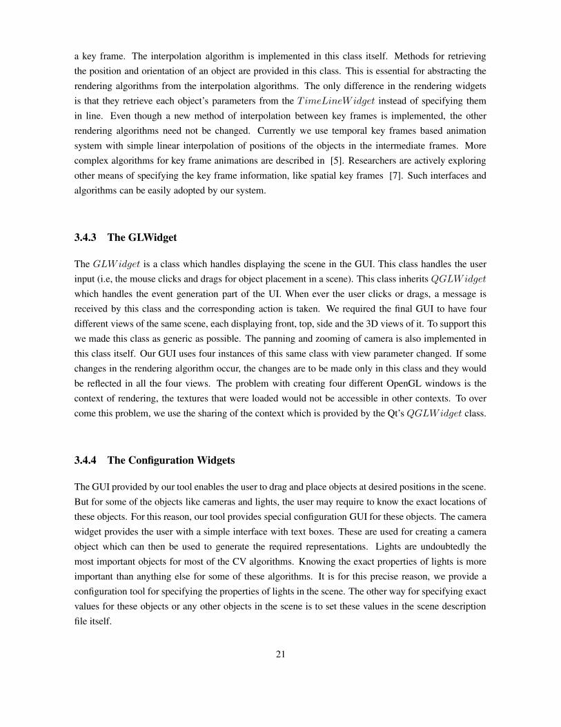
3.4 Screen Shots of GUIs of Previous versions of DGTk. . . . . . . . . . . . . . . . . . . 193.5 Class diagram for the interaction between the GUI classes. The MainWindow class
contains instances of the other GUI classes providing a single point access for the tiledrenderer. This separates different tasks which are to be handled by the whole GUI. Forexample, the dynamic scenes are completely handled by the T imeLineWidget and theMainWindow class does not have to do anything at all. Similarly the rendering andobject movement in the scene is handled by the GLWidget itself and MainWindow
class deals only with displaying these widgets. . . . . . . . . . . . . . . . . . . . . . . 20
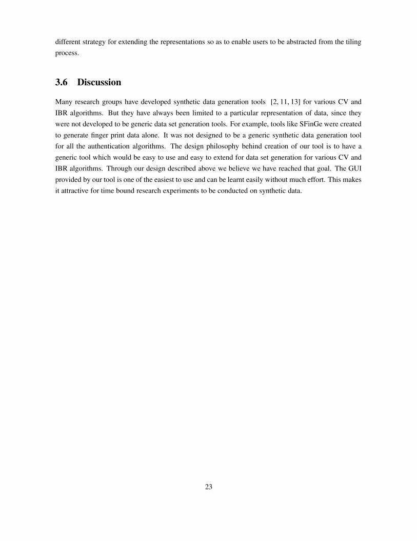
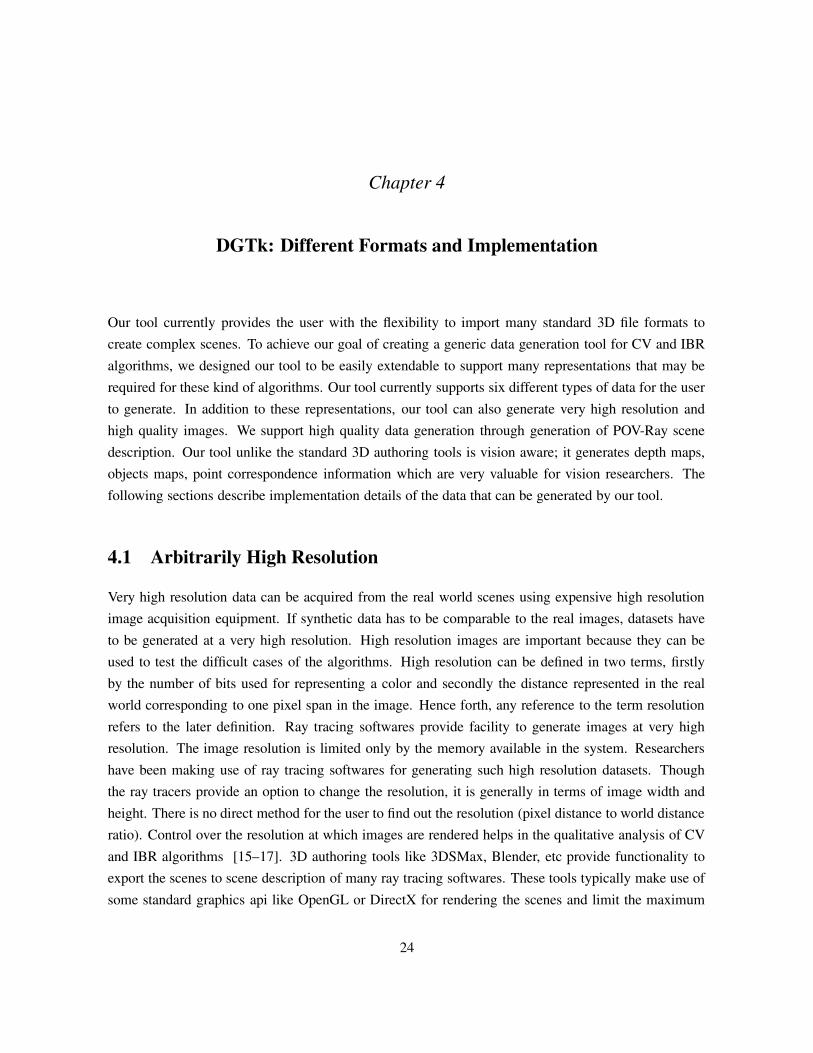
4.1 Camera Parameters . . . . . . . . . . . . . . . . . . . . . . . . . . . . . . . . . . . . 254.2 Frontal view of the frustum divided into a number of tiles (a). Top view of the same (b). 274.3 High resolution image with its’ tiles. The final image is 1280x960 with each tile ren-
dered at 320x240 resolution. . . . . . . . . . . . . . . . . . . . . . . . . . . . . . . . 274.4 (a) shows a 640x480 image created with same tile size, (b) is an image of 640x480
rendered using tiles of 320x240. If we perform image subtraction between these twoimages, the resulting image is completly black. This shows that the tiled images gener-ated by our tool are accurate to the pixel level. . . . . . . . . . . . . . . . . . . . . . . 28
x
LIST OF FIGURES xi
4.5 (a) A Smooth sphere. (b) A Bump Mapped sphere . . . . . . . . . . . . . . . . . . . . 294.6 (a) A simple scene imaged using our OpenGL renderer. (b) Ray Traced image of the
same scene. . . . . . . . . . . . . . . . . . . . . . . . . . . . . . . . . . . . . . . . . 294.7 Depth and Texture maps of different scenes. In Depth maps, brighter means closer to
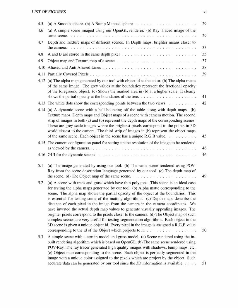
the camera. . . . . . . . . . . . . . . . . . . . . . . . . . . . . . . . . . . . . . . . . 334.8 A and B are stored in the same depth pixel . . . . . . . . . . . . . . . . . . . . . . . . 354.9 Object map and Texture map of a scene . . . . . . . . . . . . . . . . . . . . . . . . . 374.10 Aliased and Anti Aliased Lines . . . . . . . . . . . . . . . . . . . . . . . . . . . . . . 384.11 Partially Covered Pixels . . . . . . . . . . . . . . . . . . . . . . . . . . . . . . . . . . 394.12 (a) The alpha map generated by our tool with object id as the color. (b) The alpha matte
of the same image. The grey values at the boundaries represent the fractional opacityof the foreground object. (c) Shows the marked area in (b) at a higher scale. It clearlyshows the partial opacity at the boundaries of the tree. . . . . . . . . . . . . . . . . . . 41
4.13 The white dots show the corresponding points between the two views. . . . . . . . . . 424.14 (a) A dynamic scene with a ball bouncing off the table along with depth maps. (b)
Texture maps, Depth maps and Object maps of a scene with camera motion. The secondstrip of images in both (a) and (b) represent the depth maps of the corresponding scenes.These are grey scale images where the brightest pixels correspond to the points in 3Dworld closest to the camera. The third strip of images in (b) represent the object mapsof the same scene. Each object in the scene has a unique R,G,B value. . . . . . . . . . 45
4.15 The camera configuration panel for setting up the resolution of the image to be renderedas viewed by the camera. . . . . . . . . . . . . . . . . . . . . . . . . . . . . . . . . . 46
4.16 GUI for the dynamic scenes . . . . . . . . . . . . . . . . . . . . . . . . . . . . . . . 46
5.1 (a) The image generated by using our tool. (b) The same scene rendered using POV-Ray from the scene description language generated by our tool. (c) The depth map ofthe scene. (d) The Object map of the same scene. . . . . . . . . . . . . . . . . . . . . 49
5.2 (a) A scene with trees and grass which have thin polygons. This scene is an ideal casefor testing the alpha maps generated by our tool. (b) Alpha matte corresponding to thescene. The alpha map shows the partial opacity of the object at the boundaries. Thisis essential for testing some of the matting algorithms. (c) Depth maps describe thedistance of each pixel in the image from the camera in the camera coordinates. Wehave inverted the actual depth map values to generate visually appealing images. Thebrighter pixels correspond to the pixels closer to the camera. (d) The Object map of suchcomplex scenes are very useful for testing segmentation algorithms. Each object in the3D scene is given a unique object id. Every pixel in the image is assigned a R,G,B valuecorresponding to the id of the Object which projects to it. . . . . . . . . . . . . . . . . 50
5.3 A simple scene with a terrain model and grass model. (a) Scene rendered using the in-built rendering algorithm which is based on OpenGL. (b) The same scene rendered usingPOV-Ray. The ray tracer generated high quality images with shadows, bump maps, etc.(c) Object map corresponding to the scene. Each object is perfectly segmented in theimage with a unique color assigned to the pixels which are project by the object. Suchaccurate data can be generated by our tool since the 3D information is available. . . . . 51

xii LIST OF FIGURES
5.4 This figure shows six frames of a dynamic scene created using our tool. The actualsequence has fifty four frames. The major advantage of our tool is that all the represen-tations can be generated for every frame of the dynamic scene. This is not possible inmost of the available systems. The first strip of images shows the texture (actual image)of the scene through a camera. The second strip of images are the depth maps of thecorresponding scenes. The third strip of images are the object map representation ofthe scene. This is the first time where users can generate different representations ofcomplex scenes with ease. . . . . . . . . . . . . . . . . . . . . . . . . . . . . . . . . 52
A.1 (a) File menu, (b) Edit menu and (c) Tools menu. Each operation has it’s own standardicon beside the operation. . . . . . . . . . . . . . . . . . . . . . . . . . . . . . . . . . 55
A.2 The render configuration panel. This is where the user selects what outputs are to begenerated by the tool. . . . . . . . . . . . . . . . . . . . . . . . . . . . . . . . . . . . 57
A.3 The configuration dialogs for placing lights at specific locations . . . . . . . . . . . . 57A.4 The GUI for specifying the exact values for the cameras . . . . . . . . . . . . . . . . . 58
B.1 (a) A semi circular setup of 48 cameras for acquiring the images around the face model.The cameras in this scene were added not using the tool but through another programwhich generated the center and look at points of all the 48 cameras. Such large numberof cameras cannot be added manually into a scene as it is very time consuming process.(b) Images of some of the views of the camera setup. . . . . . . . . . . . . . . . . . . 63
B.2 An outdoor scene created and rendered using our data generation tool. This scene hasmultiple objects and a single camera unlike the above figure. . . . . . . . . . . . . . . 63
List of Tables
Table Page
1.1 Comparison between various synthetic data generation tools and DGTk. . . . . . . . . 6
3.1 Overview of Previous Versions of our tool. . . . . . . . . . . . . . . . . . . . . . . . . 19
xiii
Chapter 1
Introduction
Computer Vision (CV) is a discipline that emerged as a result of the efforts to make the computersunderstand the objects in the world from the images captured through cameras. In some sense CV canbe considered to be an inverse problem of Computer Graphics. Computer Graphics tries to generatea 2D image from the given world description by approximating some of the physical phenomena (i.e,lighting, materials etc). CV on the other hand deals with reconstruction of the world (3D information)from 2D image(s). A few decades ago, Televisions, mechanical toys, etc which were produced on alarge scale had to be checked by humans for faulty parts. This was a tedious process and generally errorprone. This was due to the errors which could not be detected by the naked eye. As the fields of CVand Image Processing have advanced, such fault detection have become automated. This enabled themanufacturers to produce goods which are more reliable. There are many such fields where CV hasmade strenuous, repetitive work easy.
Virtual Reality (VR) has always been in demand for entertainment and scientific simulations. The re-lentless efforts of researchers to achieve photo realistic rendering has fueled the emergence of a newfield of research called Image Based Rendering (IBR). IBR deals with algorithms which rather than re-constructing the world from 2D images, try to construct novel views of the world given some additionalinformation about the world (besides 2D images). IBR is a combination of Computer Graphics andCV. It can be used to produce photo realistic environments without any approximations involved in thephysical phenomena.
Computer Vision (CV) and Image based rendering (IBR) algorithms are used to analyze the events andstructure from videos and images given some additional information like calibration of the camera. IBRalgorithms use various intermediate structures computed from the images and other imaging parameterssuch as depth map, correspondences, etc for testing and tuning. Evaluation and tuning of CV or IBRalgorithms require high quality images with accurate ground-truth information. Acquiring such highquality ground-truth information from real world scenes is highly complicated and time consuming.The equipment required for acquiring such high resolution data is very costly too. Synthetic data is an
1
alternative widely used for testing these algorithms in the initial phases of development.
Synthetic data is useful as, qualitative and quantitative analysis of the performance of these algorithmsis possible using them. The performance of the algorithms on synthetic data is a good indicator ofit’s performance on real world images. The most important advantage of using synthetic data is thatit would help in cross checking the information reconstructed by an algorithm. Another advantage ofusing synthetic data is that it is available for free. Synthetic data clearly plays a very important role inforwarding the research in the fields of CV and IBR.
1.1 Motivation
Traditionally individual research groups and researchers have been creating their own data sets for eval-uating the performance of the algorithms they develop. The data sets so generated have become standardtest beds for benchmarking the performance of certain class of algorithms e.g, CMU Datasets [21]. Ev-ery algorithm is based upon certain fundamental assumptions about the information available and thetype of data it would encounter. For example an algorithm trying to do motion tracking would haveto make certain assumptions about the type of motion and background changes. On the other hand analgorithm trying to do face detection might have different assumptions about the information availablesay lighting conditions or the color ranges of the skin color etc. A data set created for testing a particularalgorithm may not be valid for testing the performance of a newly developed algorithm (with differentset of assumptions).
Every time an algorithm to address a new problem is designed, the researchers have to go about creatinga new data set which represents the actual data to train or test the algorithm. As generating real data athigh resolution is a very costly affair (due to the requirement of high precision apparatus), researchersresort to developing tools for generating synthetic data for analysis. These tools are generally designedonly for a specific dataset generation and cannot be used once Diversity in the data set becomes a criticalissue. For creating diversity, one has to find or build another dataset, which again is a tedious process.This is because the tools developed for synthetic data generation are generally very limited and non-scalable. A lot of time and human resources are wasted in creating datasets for even prototype testingof an CV or IBR algorithm. If this time spent on dataset creation is reduced, researchers would beable to spend their valuable time in the development of algorithm rather than development of a tool forgenerating the dataset.
A desirable tool for any researcher would be, the one which enables him/her to create complex sceneswhich mimic the real world scenes both static and dynamic without much effort. As more and morealgorithms are developed new input and output formats come into being, extensibility of the tool be-
2
comes an important factor. Clearly there is a need for a tool which would enable researchers to generaterealistic and complex datasets without much effort. This was the motivation for this thesis work.
1.2 Major Approaches
The traditional methods of data generation for CV and IBR can be categorized into three major classes.These methods are listed below:
• Data acquisition by using high precision digital equipment.
• Extending standard 3D authoring tools.
• Developing a tool for synthetic data generation.
Data acquisition using very high precision digital equipment like lacer scanners, digital cameras, etcis a very effective way to generate datasets. This method of data generation enables the researchers toacquire the real world data at a very high resolution. Since the data represents the real world objects,all the difficult cases (such as fur, water, etc) for the CV and IBR algorithms could be present in thedatasets. Though this method of acquisition is very useful, repetitive generation of data with some pa-rameters modified can be a painful process. Even the slightest of errors in the acquisition equipment canresult in corruption of the dataset. In addition to these, the major drawback of such equipment is thatthey are very costly and may not be accessible to most of the researchers.
Most of the standard 3D authoring tools provide facility to generate very high resolution synthetic data.Advanced features in rendering like bump mapping, soft shadows, motion blur, normal mapping etcwhich are common in such tools add to the realism of the synthetic data. Some of the sophisticated3D authoring tools support their own scripting language which enables the users to add additional func-tionality by writing a few lines of code. Ray tracing softwares which are known for the high qualityimagery they can produce, have their own scene description language enabling the users to generatesynthetic data. Since most of these tools are focused on generating photo realistic imagery, extendingthem to generate datasets for testing CV and IBR algorithms may be unintuitive. The major advantageof this method over data acquisition using high precision equipment is the repeatability of the datasetgeneration with a few parameters modified.
As stated before, extending standard 3D authoring tools for generating required data may not alwaysbe very easy to accomplish. This is where researchers have no other option but to create their tool forgenerating the datasets. Such tools are very fine tuned for generating a specific dataset. Extending themto generate datasets for other algorithms may be virtually impossible. This method of dataset creation isvery time consuming due to the development time involved (for developing a whole new data generationtool). The advantage of development of such a tool is that it could be used for generating datasets for
3

most of the algorithms that try to address the same problem as the algorithm it was originally developedfor.
1.3 Objectives
Synthetic data plays an important role in testing and training of CV and IBR algorithms. This is becauseacquiring real world images is costly and tedious process. We believe that a generalized synthetic datageneration tool kit with the following features would be a boon for many researchers working in theareas of CV and IBR. The development of such a tool would help researchers to quickly check if acertain technique is working or not, without worrying about the availability of datasets.
Our objective was to create such a generic tool kit and make it available to the research community. Wehave set for ourselves a set of requirements that have to be satisfied, for a data generation tool to beuseful for generating datasets for any CV or IBR algorithm.
1.3.1 Versatility
CV and IBR algorithms are generally developed for solving some real world problems like MotionTracking, Biometrics based Identification, 3D reconstruction and visualization, etc. The inputs to thesealgorithms range from, simple images to video sequences with depth information, etc. For this reason,the data generation tool should allow creation of complicated scenes that mimic the real world. The realworld scenes are not always static. Hence such a tool should provide functionality to generate dynamicscenes. Datasets which have dynamic objects in the world are important for the analysis of Motiontracking, 3D reconstruction and other algorithms which operate on video sequences.
1.3.2 High Quality
The quality of images and ground truth are very critical for testing CV and IBR algorithms. Thoughsynthetic data cannot be photo realistic, such a tool should strive to produce data which is comparableto the data produced using high precision data acquisition equipment. The tool should provide somecontrol over the quality of the output generated. Such a feature would enable the user to evaluate therobustness of an algorithm. Though most of the visible colors can be represented using 32-bits percolors, some applications might require a higher quality color representation (e.g, 48-bits per color).Such high quality features are to be made easily accessible to the user.
1.3.3 Flexibility
Since the problem we are trying to address is very general covering a large spectrum of algorithms, thedata generation tool kit should be flexible enough to provide the user with different choices. The choices
4

begin right from the format of the 3D models supported as input for creating scenes. There are hundredsof file formats for storing and sharing 3D graphics models, supporting at least a few of the most popularformats is essential for the tool to be usable. Such a data generation tool should be flexible enough toenable the user to setup very complex camera configurations (e.g, dome configuration, etc) once thescene is setup.
1.4 Contributions of the Thesis
The primary contribution of this work is in the creation of a tool useful for individual researchers togenerate high quality, ground truth data and share it with others. Our tool is computer vision aware; it isnot just another graphics authoring tool. It therefore generates depth maps, calibration matrices, corre-spondences, etc., which are valuable to computer vision researchers. Conventional graphics authoringtools focus on setting up the 3D world and generating views of it. The data generation capability canbe added as additional functionality to tools like 3DStudio Max or Blender. But such extensions aregenerally very unintuitive and difficult because the internal implementation details are hidden from theusers. In addition to this, the commercial 3D authoring tools like 3D Studio Max, Maya etc are veryexpensive and may not be accessible to every one. Open source 3D modeling tools (e.g Blender) aredifficult to use or unstable. We chose to create a new tool of our own since the requirements are differ-ent. We may need to represent additional type of information about the environment which can requireunintuitive extensions to the existing file formats. A simple, open-source tool that can import standardmodels but has an internal structure that suits computer vision applications is preferable. Since the usershave access to the code, they would be able to extend the tool to support the required data. We designedour tool to work intuitively along side these tools rather than extend any of them.
(a) (b)
Figure 1.1 Some scenes made using our tool. (a) Rendered using our tool’s internal renderer. (b)Rendered using povray from the scene description generated by our tool.
5
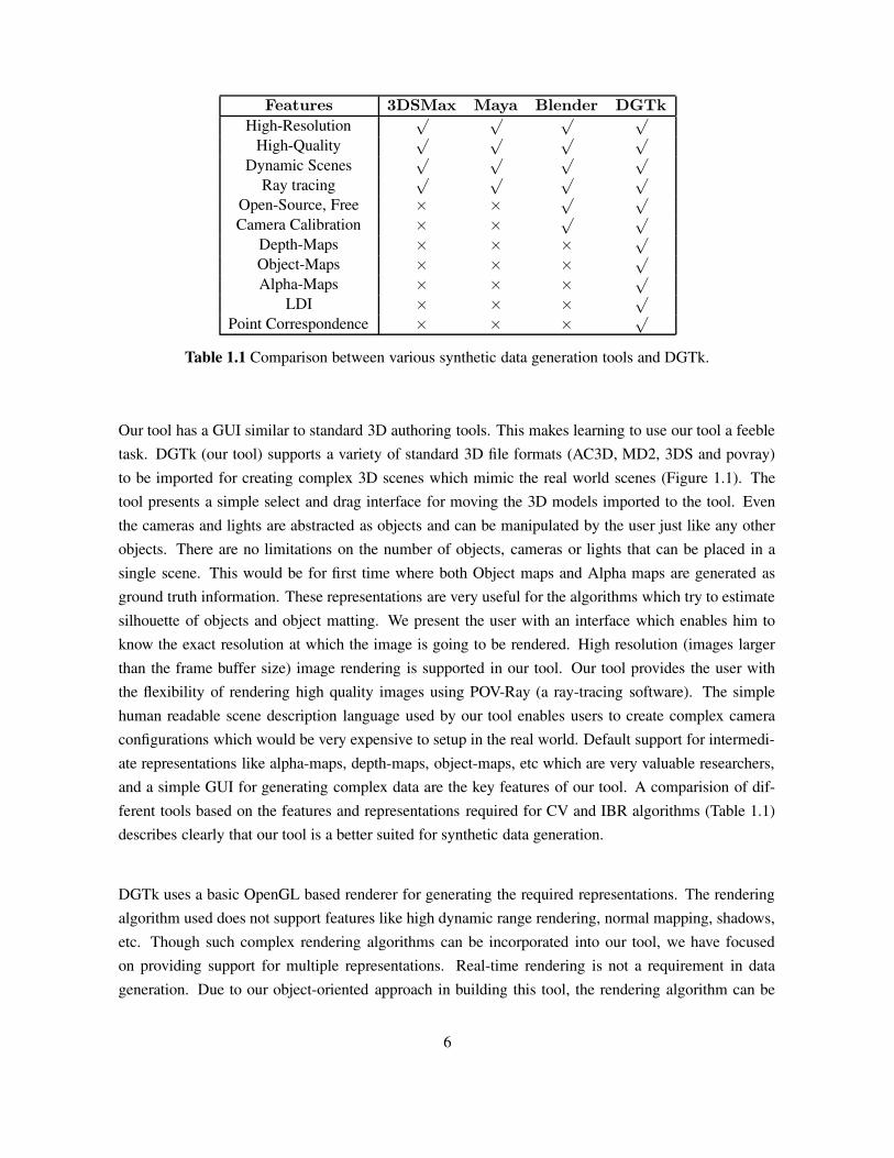
Features 3DSMax Maya Blender DGTk
High-Resolution√ √ √ √
High-Quality√ √ √ √
Dynamic Scenes√ √ √ √
Ray tracing√ √ √ √
Open-Source, Free × × √ √
Camera Calibration × × √ √
Depth-Maps × × × √
Object-Maps × × × √
Alpha-Maps × × × √
LDI × × × √
Point Correspondence × × × √
Table 1.1 Comparison between various synthetic data generation tools and DGTk.
Our tool has a GUI similar to standard 3D authoring tools. This makes learning to use our tool a feebletask. DGTk (our tool) supports a variety of standard 3D file formats (AC3D, MD2, 3DS and povray)to be imported for creating complex 3D scenes which mimic the real world scenes (Figure 1.1). Thetool presents a simple select and drag interface for moving the 3D models imported to the tool. Eventhe cameras and lights are abstracted as objects and can be manipulated by the user just like any otherobjects. There are no limitations on the number of objects, cameras or lights that can be placed in asingle scene. This would be for first time where both Object maps and Alpha maps are generated asground truth information. These representations are very useful for the algorithms which try to estimatesilhouette of objects and object matting. We present the user with an interface which enables him toknow the exact resolution at which the image is going to be rendered. High resolution (images largerthan the frame buffer size) image rendering is supported in our tool. Our tool provides the user withthe flexibility of rendering high quality images using POV-Ray (a ray-tracing software). The simplehuman readable scene description language used by our tool enables users to create complex cameraconfigurations which would be very expensive to setup in the real world. Default support for intermedi-ate representations like alpha-maps, depth-maps, object-maps, etc which are very valuable researchers,and a simple GUI for generating complex data are the key features of our tool. A comparision of dif-ferent tools based on the features and representations required for CV and IBR algorithms (Table 1.1)describes clearly that our tool is a better suited for synthetic data generation.
DGTk uses a basic OpenGL based renderer for generating the required representations. The renderingalgorithm used does not support features like high dynamic range rendering, normal mapping, shadows,etc. Though such complex rendering algorithms can be incorporated into our tool, we have focusedon providing support for multiple representations. Real-time rendering is not a requirement in datageneration. Due to our object-oriented approach in building this tool, the rendering algorithm can be
6
changed without effecting the other parts of teh tool. Our tool supports such high quality data bygenerating scene description used by POV-Ray, which can be used to generate very high quality images.
1.5 Organization of the Thesis
The thesis is organized as follows:
In Chapter 2 we give an overview of the techniques and types of data currently available. We haveclassified the related work into these three groups. We also provide a brief overview about the type,resolution of the data generated in their work. In Chapter 3, we describe the design requirements for asynthetic data generation tool. This requirement analysis is based on our observation of the limitationsin the previous work. We then go about describing the development cycle of our tool. We describe howthe tool has evolved from a simple program which takes command line arguments and renders high res-olution images to a fully functional GUI based tool for data generation. We describe the objectives wehave achieved through the design of our tool. Chapter 4 describes various data formats that our tool cangenerate. Each section describes a file format, it’s uses and the implementation details for generatingthat format. We also discuss some of the features of our tool which make it easy to use for synthetic datageneration. The representations of 3D scenes generated by our tool are showcased in Chapter 5. Chap-ter 6 is a summary of what we have achieved by developing such a data generation tool. We also providesome of the future possibilities to be explored. In Chapter B, we provide a detailed overview of the fileformat we have designed for representing a scene created using our data generation tool. We discussthe merits of such a standard representation for scene representation. We also discuss why the currentscene description languages provided by most of the rendering softwares are inadequate for this purpose.
7
Chapter 2
Related work
The researchers all over the world have been actively creating and sharing datasets (both real and syn-thetic) which enabled the comparison of the performance of different algorithms which address the sameproblem (e.g, 3D depth map construction, Motion tracking, Object Detection, etc). We have classifiedthe previous work done into three major sections, (1) Data Acquisition using High-Resolution Equip-ment, (2) Extending existing tools for Data Acquisition and (3) Data Generation Tools for generatingSynthetic Data.
2.1 Data Acquisition using High-Resolution Equipment
In an attempt to provide a generic platform for comparing the performance of Stereo matching algo-rithms, Scharstein and Szeliski [15] have designed a collection of data sets. Their work goes beyondjust creating datasets, and presents a comparison between some of the stereo algorithms along with aninsight of their working. The datasets were created by acquiring images using a high-resolution camera.
The development in the stereo matching algorithms have outpaced the ability of standard datasets todiscriminate among the best performing algorithms. In 2003, one year after their previous work, Szel-ski [16] was developed to create more challenging scenes with accurate ground truth information. Inthis work a method for acquiring high-complexity stereo image pairs with pixel accurate correspondenceinformation using structured light is explained. The data acquisition equipment consisted of a pair ofhight-resolution cameras and one or more projectors that cast structured light patterns. The datasetscreated using this method were made available for the research community to use.
In a more recent work, Steven at al [17] present a method for acquiring and calibrating multi view im-age datasets with high-accuracy ground truth. These high-accuracy calibrated multi-view image datasetshelped in the qualitative comparison of stereo reconstruction algorithms which was not possible before.The datasets described in this work were generated using the Stanford spherical gantry, a robotic arm.Images were captured using a CCD camera with a resolution of 640x480 pixels attached to the tip of
8

the gantry arm. One pixel in the image acquired roughly spanned 0.25mm on the object surface.
Fellenz [4] have developed a low cost vision head for enhancing the dense depth maps. CMU over theyears has developed a large number of data sets which have become the standard test data sets e.g, CMUPIE database [21], etc.
In all the work referred above, the data had been acquired using a high resolution camera along withsome highly calibrated apparatus. As a result, the datasets are highly accurate and very realistic. Themain disadvantages of datasets generated using such equipment are:
• Advances in algorithm development may lead to datasets becoming obsolete.
• Recreation of the data at a higher resolution may be virtually impossible.
• Minute errors in the calibration of the apparatus may lead to corrupt datasets.
2.2 Extending existing Tools for Data Acquisition
Though very high quality data acquired using high precision digital devices is available for usage byother researchers, the inherent problems (described above) involved in such datasets resulted in in-creased use of Synthetic datasets. The synthetic data has the advantage of repeatability of the datasetswith some modified parameters. Standard Computer Graphics (CG) tools like Ray tracing softwaresand 3D authoring tools have been traditionally modified or extended to generate synthetic data.
Ray tracing softwares which are very popular in the CG community, are capable of producing very highquality images of 3D scenes. Over the past decade, ray tracing softwares have evolved into complexsoftware systems. These softwares now have their own scene description language which are powerfultools for creating complex scenes. Some of the ray tracing softwares support animation scripts for theobjects in the scenes. While some of the ray tracers have tried to simulate various types of lens effects,particle effects and projection types, others have tried to achieve realistic light simulation. A more com-prehensive comparison among some of the free ray tracing softwares is presented in Haynes [6]. Thepower of ray tracing softwares to create and render realistic scenes that mimic the real world scenes,makes them a good option for creating datasets. Since these softwares are designed only to generateimages, it is not feasible to extend these to generate intermediate representations like object maps, cor-responding points, etc.
Standard 3D authoring tools take the data generation to next level by providing flexible User Interfaces(UI) for setting up complex 3D scenes. This makes the scene setup a lot easier compared to writing thescenes in text. The 3D authoring tools (both commercial and free) such as 3DSMax, Maya, blender etcare capable of rendering high resolution images using ray tracing, But they do not generate depth maps,
9
Calibration data, Corresponding points, Layer depth images etc by default, which are typically requiredfor testing CV and IBR algorithms. Fortunately these 3D authoring tools provide the flexibility to theuser to extend the functionality by writing simple scripts. For example 3DSMax supports MAX scripts,Maya has it’s own scripting engine which supports MEL scripts, Blender (an open source 3D authoringtool) allows users to write python scripts for extending its functionality.
The commercial products like 3DSMax, Maya are very costly and hence may not be accessible toeveryone. Though blender is a free software and has many features for animation and rendering, it’sUI is considered unintuitive. Once the users become familiar with it’s interface, it is a very good toolto use for data generation. Some of the researchers [9, 11, 13] have tried to extend blender to producecomputer vision data like depth maps, camera calibration information, etc.
Figure 2.1 A frame from the first ever open movie ”Elephant’s Dream”. This movie was created fromscratch using blender for modeling and rendering. The project proved that such cinematic quality ren-dering can be achieved through open source tools. The creation of this movie has fueled the developmentof blender. Many tools which make animation easier have been added based on the feed back from thedevelopers of this movie. (Courtesy Orange the open movie project.)
2.2.1 Blender review
Blender is an Open source multi-platform 3D modeling and animation suite. It has support for Win-dows 98+, Mac OS 10.2+, Linux (i386 and PPC), Solaris (Sparc), FreeBSD, and even Irix (mips3).It has grown into a complex tool since it has been licensed under the GNU GPL in 2002. The movie”Elephant’s Dream”, the first ever open movie was made using blender. The current version 2.42 hasenhanced character animation tools. It’s development has been boosted since the release of the ”Ele-
10

phant’s Dream” movie. Many enhancements to the animation tools were a result of the feedback fromthe blender community. Blender has one of the fastest ray tracing engines for rendering the scenes. Therendering pipeline till recently did not have tiling support and hence the images rendered were limitedby the frame buffer size. The current version (blender 2.42) has tiling support where each tile is renderedin a separate thread. Blender provides an excellent interface for creating organic models (e.g, modelslike monsters, humans, plants, trees, terrains etc). Blender supports bone animation through objectscalled armatures which provide both forward and inverse kinematics. Though these features enable forvery complex animations, they are daunting to use, even for intermediate users.
Since the early versions, this tool has relied greatly on keyboard shortcuts. This makes the tool hard tolearn. In the more recent versions, the development team has tried to over come this problem by pro-viding most of the operations as menu items and buttons. Though this helps intermediate users, noviceusers still find it difficult to use the tool because of too many menus and shortcut keys. The reference ofshortcuts provided by the developers runs to nearly nine pages. Such complex systems are hard to usefor novice users. On the other side, once the tool is mastered, it is the best tool available. In additionto modeling, rigging and animating, blender’s users can develop small games by making use of gameengine provided in it. This game engine features collision detection, physics simulation and many more.Blender has several areas where it can improve. Lack of simple interface is one of the most importantdrawbacks. The UI provided is very flexible and can be changed to imitate any of the standard UIs. Butthe scope of functionalities provided by blender is so broad that one can easily become lost in all ofthe options. Even a simple task like changing the material property of a surface requires clicking andselecting multiple options. One of the best things about blender is it’s support for plug-ins in the formof python scripts. This enables users to write scripts to export as well as import models in their ownfile format. Unfortunately the python api of blender is very huge. It may be difficult to find the rightclasses for implementing an extension. On the brighter side, it has a great support; For example, theBlender Web site features a bug tracker any user can post in. Most of the submitted bugs usually fixedwithin days, and new testing builds are available almost every week. In addition to these, there are manyon-line tutorials available on the Internet which are specifically designed for novice users.
On the whole blender is a great 3D suite for modeling and animation. Due to it’s complexity, it may bedifficult for new users to adopt this tool. This is the main reason why most researchers tend to developtheir own tools for data generation rather than extending blender using it’s scripting capability.
2.2.2 3DSMax review
3DSMax is a commercial 3D authoring tool popular among the game development and other industriesbased on computer generated imagery (CGI). It was one of the softwares which pioneered in providingUI for character animation. This tool has been up to date with the current state of the art interfaces
11
available for various modeling and animation requirements.
3DSMax has a very powerful network based rendering system which makes use of all the nodes con-nected in the network for rendering a scene at very high resolution. This tool has a plug-in systemwhich enables the users to change the rendering algorithms, export new representations of a scene oreven import a new file format. The scripting provided by these tools enables artists to create animationswith very high precision. AutoDesk the developers of 3DSMax have designed their own proprietaryscene description for 3DSMax which has evolved into a powerful representation which allows users tostore animation information as well. 3DSMax 8 (the latest version of 3DSMax) has a very unique easyto use UI for adding hair to a model. The user can groom the hair of the character using a comb controlprovided as a part of styling interface. This interface a short learning curve compared to Maya’s hairmodeling system. In addition to this, Max has support for cloth simulation. Once a mesh is specifiedas a cloth, the internal simulation engine manages the movement of the cloth in the scene. All thesefeatures in such tool are focused on making the UI better for artists. The character studio which isprovided as a part of 3DS Max is perhaps one of the best systems available for creating character an-imations. Such complex features like Inverse Kinematics, Quaternions, Curve-editing etc are used forprovide maximum control of the animations. These tools are better suited for artists and are really anoverkill for data generation for CV and IBR. To obtain the best performance, these tools try to optimizethe rendering algorithms so as to generate images of scenes quickly and provide the artists with moretime to create and modify the animations.
The number tools provided in this software is enormous. Users can write scripts for camera motion inthe scene or even develop plug-ins for supporting different file formats. This is not generally enough forthe data generation requirements. For generating different representations of a scene (i.e, depth maps,alpha maps, ldi, etc), the user requires a through insight of the internal data structures used in the tool.This is clearly not possible in closed source, commercial softwares like 3DSMax.
2.3 Data Generation Tools for Specific Data
Due to the increased adoption of finger print based authentication systems, methodical and accurateperformance evaluation of finger print recognition algorithms is required. Since collecting large fingerprint databases is expensive and problematic due to the privacy legislation, a method for generatingsynthetic finger prints had to be constructed [2]. In Capelli [2] the author presents a method for gen-erating synthetic finger print data based on few parameters. When extending existing tools to generatethe required datasets is not possible, researchers have no other option but to develop their own tool forthe data generation. For example, representations like Layer Depth Images (Shade et al [18]) cannot begenerated by extending the existing tools. In their work the authors describe a few methods for acquiringthe datasets for the algorithm.
12
2.4 Summary
The increase in the pace of development of CV and IBR algorithms led to a situation where thecurrent datasets have become inadequate and can no longer be used for qualitative comparison of newhigh quality algorithms. All the time and revenue spent in gathering such datasets could become wasted.Researchers have tried to over come this problem by providing data generation tools for some specificproblems. Though such tools help in generation of datasets, they are generally very limited in termsof extendability and type of data generated. Some of the commercial authoring tools like 3DSMax,Maya, etc are either very costly or cannot be extended due to lack of information about the internalrepresentation of data in these tools. Open source tools like blender have a very complex ui which isdifficult to use. Due to constant change in the architecture of the system, it may be difficult to updatethe data generation scripts. In addition to these, since such tools are specifically designed for modelingand animation, it may require un-intuitive extensions to the current file formats. A single versatile,extendable, flexible tool for generating data for CV and IBR algorithms would help in improving thepace of algorithm development by reducing the time spent in data acquisition.
13

Chapter 3
DGTk: Design
3.1 Design Details
The data generation tools available are generally developed for generation of a specific type of data setsonly. For example data generation for finger print identification, Corresponding Points, etc. Thoughsuch tools are capable of generating high quality data, they may become unusable due to their limitedextendability. A tool kit which can generate more than one type of datasets and is extend able would bevery useful for CV and IBR research community. Based on our analysis of the tools available for datageneration, (Chapter 2), we have come up with a design for a generic data generation tool.
In this chapter, we present the design details of DGTk a toolkit to generate data for computer visionand image-based rendering algorithms. The goal of such a toolkit is to enable individual researchers togenerate high quality synthetic data and to help them share the datasets with others in the community.DGTk is designed to be a standalone toolkit using which one can create a scene consisting of cameras,lights, geometric objects, etc. For versatility, the tool allows the user to import 3D models in standard
Figure 3.1 Screen Shot of the Tool
14
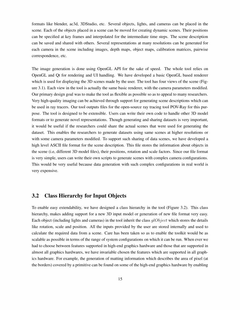
formats like blender, ac3d, 3DStudio, etc. Several objects, lights, and cameras can be placed in thescene. Each of the objects placed in a scene can be moved for creating dynamic scenes. Their positionscan be specified at key frames and interpolated for the intermediate time steps. The scene descriptioncan be saved and shared with others. Several representations at many resolutions can be generated foreach camera in the scene including images, depth maps, object maps, calibration matrices, pairwisecorrespondence, etc.
The image generation is done using OpenGL API for the sake of speed. The whole tool relies onOpenGL and Qt for rendering and UI handling. We have developed a basic OpenGL based rendererwhich is used for displaying the 3D scenes made by the user. The tool has four views of the scene (Fig-ure 3.1). Each view in the tool is actually the same basic renderer, with the camera parameters modified.Our primary design goal was to make the tool as flexible as possible so as to appeal to many researchers.Very high-quality imaging can be achieved through support for generating scene descriptions which canbe used in ray tracers. Our tool outputs files for the open-source ray tracing tool POV-Ray for this pur-pose. The tool is designed to be extensible. Users can write their own code to handle other 3D modelformats or to generate novel representations. Though generating and sharing datasets is very important,it would be useful if the researchers could share the actual scenes that were used for generating thedataset. This enables the researchers to generate datasets using same scenes at higher resolutions orwith some camera parameters modified. To support such sharing of data scenes, we have developed ahigh level ASCII file format for the scene description. This file stores the information about objects inthe scene (i.e, different 3D model files), their positions, rotation and scale factors. Since our file formatis very simple, users can write their own scripts to generate scenes with complex camera configurations.This would be very useful because data generation with such complex configurations in real world isvery expensive.
3.2 Class Hierarchy for Input Objects
To enable easy extendability, we have designed a class hierarchy in the tool (Figure 3.2). This classhierarchy, makes adding support for a new 3D input model or generation of new file format very easy.Each object (including lights and cameras) in the tool inherit the class glObject which stores the detailslike rotation, scale and position. All the inputs provided by the user are stored internally and used tocalculate the required data from a scene. Care has been taken so as to enable the toolkit would be asscalable as possible in terms of the range of system configurations on which it can be run. When ever wehad to choose between features supported in high-end graphics hardware and those that are supported inalmost all graphics hardwares, we have invariable chosen the features which are supported in all graph-ics hardware. For example, the generation of matting information which describes the area of pixel (atthe borders) covered by a primitive can be found on some of the high-end graphics hardware by enabling
15
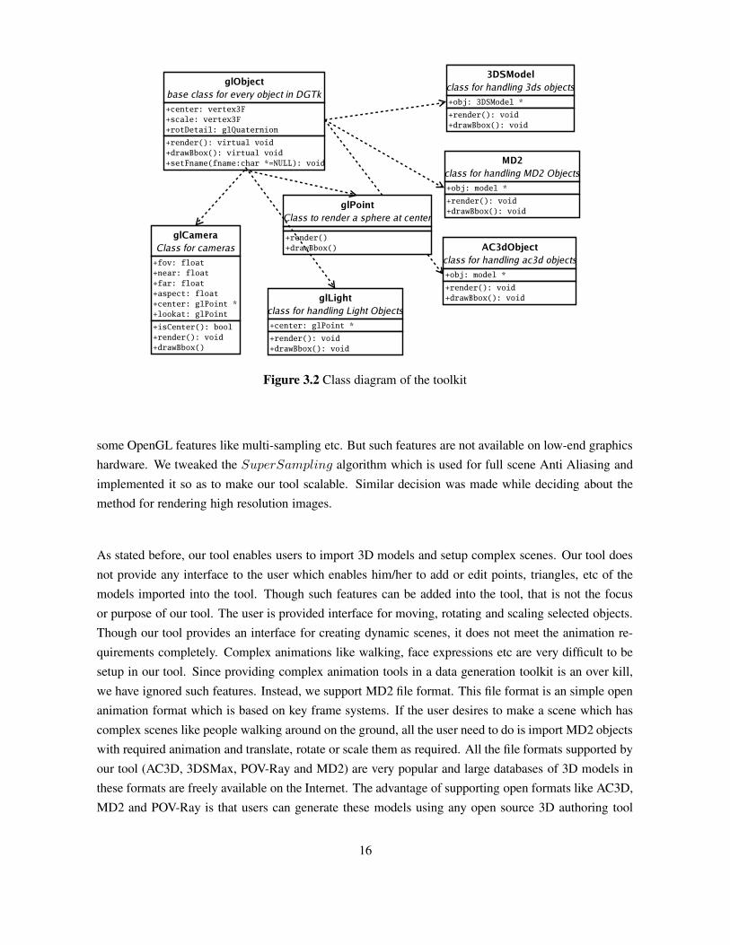
Figure 3.2 Class diagram of the toolkit
some OpenGL features like multi-sampling etc. But such features are not available on low-end graphicshardware. We tweaked the SuperSampling algorithm which is used for full scene Anti Aliasing andimplemented it so as to make our tool scalable. Similar decision was made while deciding about themethod for rendering high resolution images.
As stated before, our tool enables users to import 3D models and setup complex scenes. Our tool doesnot provide any interface to the user which enables him/her to add or edit points, triangles, etc of themodels imported into the tool. Though such features can be added into the tool, that is not the focusor purpose of our tool. The user is provided interface for moving, rotating and scaling selected objects.Though our tool provides an interface for creating dynamic scenes, it does not meet the animation re-quirements completely. Complex animations like walking, face expressions etc are very difficult to besetup in our tool. Since providing complex animation tools in a data generation toolkit is an over kill,we have ignored such features. Instead, we support MD2 file format. This file format is an simple openanimation format which is based on key frame systems. If the user desires to make a scene which hascomplex scenes like people walking around on the ground, all the user need to do is import MD2 objectswith required animation and translate, rotate or scale them as required. All the file formats supported byour tool (AC3D, 3DSMax, POV-Ray and MD2) are very popular and large databases of 3D models inthese formats are freely available on the Internet. The advantage of supporting open formats like AC3D,MD2 and POV-Ray is that users can generate these models using any open source 3D authoring tool
16
like blender and use them for data generation, all at free of cost.
Figure 3.3 The class diagram of the output representations. Tiled renderer is the class responsible forgenerating the final output representations. The input to this renderer is the glCamera. This objectprovides the parameters set by the user in the RenderConfig class (i.e, the image dimensions, tiledimensions, etc). The GLWidget class is the class used for setting up the scene. This class handles theobject movement etc and hence provides the object positions, camera positions.
3.3 Output Class Hierarchy
We have developed a c++ class for rendering the scene. This class has different methods each for ren-dering a separate representation of the scene. The class provides a single method for rendering all theframes of a single camera. This is done because, the user may require the tool to render different cameraviews at different resolutions. Once the user starts the rendering process, these parameters are used tocalculate the image resolution and the number of tiles to be rendered. These parameters are passed tothe tile renderer as function arguments in the form of the camera class. Tile renderer uses this camerainformation to render the final output (Figure 3.2). If the user needs to generate a new representation,he/she needs to add another method to the tile render class and invoke it for every tile render. The advan-tage of this method of implementation is that the user is completely abstracted from the tiling processand hence very high resolution representations can be generated without any difficulty. The renderer is
17
built using OpenGL with support for texturing, lighting and materials. This means that every renderingoperation in our tool has to be done using OpenGL. Since OpenGL is the industry standard for renderingoperations, we have decided to use it for our rendering purposes.
RenderConfig is a class which provides the user with GUI for setting up the camera resolution foreach camera in the scene. It also provides a number of check boxes each for rendering a different repre-sentation. Based on the user’s selection of these check boxes, a flag variable is set and passed to the tiledrenderer where it will be used for generating different representations of the scene. The RenderConfig
class also sets some of the attributes like image dimensions, tile dimensions for each camera objectwhich is passed to the tiled renderer. The tiled renderer uses this information for calculating the numberof tiles, view frustum for each of the tiles and generates the output. These representations include thedepth maps, tiled images, full high resolution images, POV-Ray scene description for high quality ren-dering, Object maps, matting information in terms of alpha maps, point correspondence and layer depthimages. Each of these representations is implemented as a separate method in the T iledRenderer.
3.4 GUI Class Hierarchy
Many 3D authoring tools have strive to achieve perfection in their user interfaces. These tools haveGUIs that have been rigorously tested so as to make sure that the learning curve for the users is as min-imal as possible. We tried to achieve the same perfection in the GUI of our tool. The time line featurein our tool, which is useful for creating dynamic scenes, is an inspiration from a popular 2D anima-tion software called Macromedia Flash. There were many iterations in the development cycle, wherewe constantly changed the UI before achieving the current UI. We considered implementing innovativesketch based modeling interface for creating models described in [8] for our tool. This idea was laterdiscarded since creating 3D models is not the focus or purpose of our tool. Our tool evolved from asimple command line rendering tool to a fully featured tool with very easy to use UI which mimicsstandard 3D authoring tools (Table 3.1).
3.4.1 The Main Window
The GUI of our tool is composed of six major components. The MainWindow class is used forcreating the main GUI window with four frames, each for a different view of the scene in the tool.This class contains instances of the GUI for configuring cameras, lights, rendering parameters etc. Thisclass is responsible for providing the menu interface along with the tool bar buttons for performingbasic operations like opening a file or saving a file. These also include editing operations like cut,copy and paste. Since interfaces for specifying the render parameters for the cameras, lights, differentrepresentations and the dynamic scenes are part of the whole tool, we have put instances of GUI for
18

Version UI Input OutputV 0.1 command line AC3D High Resolution ImagesV 0.2 GUI (Figure 3.4(a)) AC3D High Resolution ImagesV 0.8 GUI (Figure 3.4(b)) AC3D, Stan-
dard ShapesHigh Resolution Images,Povray Files, Depth Maps
V 1.0 GUI (Figure 3.1) AC3D,MD2, 3DS,POV-Ray
High Resolution Images,Depth Maps, ObjectMaps, LDI, MattingImages, LDI
Table 3.1 Overview of Previous Versions of our tool.
(a) (b)
Figure 3.4 Screen Shots of GUIs of Previous versions of DGTk.
these configurations as part of the MainWindow class (Figure 3.4.1). This enables easy access to therender parameters for the final tile renderer. For example, the main interface has a play button whichcan be used to preview the animations in the main window itself. This is possible due to the interactionbetween the GLWidget, T imeLineWidget and the MainWindow. Once the play button is clickedin the main window it sets the animation variable in the GLWidget and the GLWidget window startstaking the interpolated values of the object’s properties from the T imeLineWidget. This is possiblebecause we maintain a global variable for the time line and the objects as well. The following sectionsdescribe in detail each of the GUI classes.
3.4.2 The TimeLineWidget
This is a custom made widget which looks like a modified version of the Macromedia flash’s time lineGUI. This widget is a Qt class for handling the creation of dynamic scenes. This class is the responsiblefor providing the user with the interface for providing information about the key frames for the dynamicscene. This class has it’s own popup menu to support the basic functionalities required like making
19

Figure 3.5 Class diagram for the interaction between the GUI classes. The MainWindow class con-tains instances of the other GUI classes providing a single point access for the tiled renderer. Thisseparates different tasks which are to be handled by the whole GUI. For example, the dynamic scenesare completely handled by the T imeLineWidget and the MainWindow class does not have to doanything at all. Similarly the rendering and object movement in the scene is handled by the GLWidget
itself and MainWindow class deals only with displaying these widgets.
20
a key frame. The interpolation algorithm is implemented in this class itself. Methods for retrievingthe position and orientation of an object are provided in this class. This is essential for abstracting therendering algorithms from the interpolation algorithms. The only difference in the rendering widgetsis that they retrieve each object’s parameters from the T imeLineWidget instead of specifying themin line. Even though a new method of interpolation between key frames is implemented, the otherrendering algorithms need not be changed. Currently we use temporal key frames based animationsystem with simple linear interpolation of positions of the objects in the intermediate frames. Morecomplex algorithms for key frame animations are described in [5]. Researchers are actively exploringother means of specifying the key frame information, like spatial key frames [7]. Such interfaces andalgorithms can be easily adopted by our system.
3.4.3 The GLWidget
The GLWidget is a class which handles displaying the scene in the GUI. This class handles the userinput (i.e, the mouse clicks and drags for object placement in a scene). This class inherits QGLWidget
which handles the event generation part of the UI. When ever the user clicks or drags, a message isreceived by this class and the corresponding action is taken. We required the final GUI to have fourdifferent views of the same scene, each displaying front, top, side and the 3D views of it. To support thiswe made this class as generic as possible. The panning and zooming of camera is also implemented inthis class itself. Our GUI uses four instances of this same class with view parameter changed. If somechanges in the rendering algorithm occur, the changes are to be made only in this class and they wouldbe reflected in all the four views. The problem with creating four different OpenGL windows is thecontext of rendering, the textures that were loaded would not be accessible in other contexts. To overcome this problem, we use the sharing of the context which is provided by the Qt’s QGLWidget class.
3.4.4 The Configuration Widgets
The GUI provided by our tool enables the user to drag and place objects at desired positions in the scene.But for some of the objects like cameras and lights, the user may require to know the exact locations ofthese objects. For this reason, our tool provides special configuration GUI for these objects. The camerawidget provides the user with a simple interface with text boxes. These are used for creating a cameraobject which can then be used to generate the required representations. Lights are undoubtedly themost important objects for most of the CV algorithms. Knowing the exact properties of lights is moreimportant than anything else for some of these algorithms. It is for this precise reason, we provide aconfiguration tool for specifying the properties of lights in the scene. The other way for specifying exactvalues for these objects or any other objects in the scene is to set these values in the scene descriptionfile itself.
21
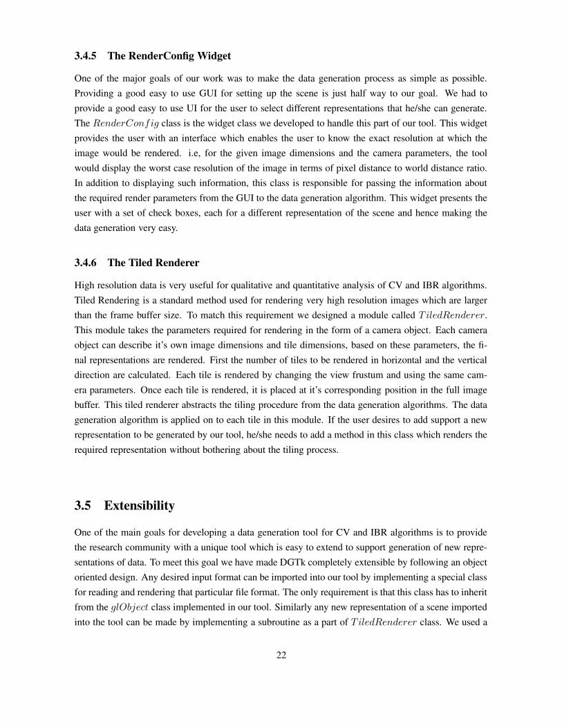
3.4.5 The RenderConfig Widget
One of the major goals of our work was to make the data generation process as simple as possible.Providing a good easy to use GUI for setting up the scene is just half way to our goal. We had toprovide a good easy to use UI for the user to select different representations that he/she can generate.The RenderConfig class is the widget class we developed to handle this part of our tool. This widgetprovides the user with an interface which enables the user to know the exact resolution at which theimage would be rendered. i.e, for the given image dimensions and the camera parameters, the toolwould display the worst case resolution of the image in terms of pixel distance to world distance ratio.In addition to displaying such information, this class is responsible for passing the information aboutthe required render parameters from the GUI to the data generation algorithm. This widget presents theuser with a set of check boxes, each for a different representation of the scene and hence making thedata generation very easy.
3.4.6 The Tiled Renderer
High resolution data is very useful for qualitative and quantitative analysis of CV and IBR algorithms.Tiled Rendering is a standard method used for rendering very high resolution images which are largerthan the frame buffer size. To match this requirement we designed a module called T iledRenderer.This module takes the parameters required for rendering in the form of a camera object. Each cameraobject can describe it’s own image dimensions and tile dimensions, based on these parameters, the fi-nal representations are rendered. First the number of tiles to be rendered in horizontal and the verticaldirection are calculated. Each tile is rendered by changing the view frustum and using the same cam-era parameters. Once each tile is rendered, it is placed at it’s corresponding position in the full imagebuffer. This tiled renderer abstracts the tiling procedure from the data generation algorithms. The datageneration algorithm is applied on to each tile in this module. If the user desires to add support a newrepresentation to be generated by our tool, he/she needs to add a method in this class which renders therequired representation without bothering about the tiling process.
3.5 Extensibility
One of the main goals for developing a data generation tool for CV and IBR algorithms is to providethe research community with a unique tool which is easy to extend to support generation of new repre-sentations of data. To meet this goal we have made DGTk completely extensible by following an objectoriented design. Any desired input format can be imported into our tool by implementing a special classfor reading and rendering that particular file format. The only requirement is that this class has to inheritfrom the glObject class implemented in our tool. Similarly any new representation of a scene importedinto the tool can be made by implementing a subroutine as a part of T iledRenderer class. We used a
22
different strategy for extending the representations so as to enable users to be abstracted from the tilingprocess.
3.6 Discussion
Many research groups have developed synthetic data generation tools [2, 11, 13] for various CV andIBR algorithms. But they have always been limited to a particular representation of data, since theywere not developed to be generic data set generation tools. For example, tools like SFinGe were createdto generate finger print data alone. It was not designed to be a generic synthetic data generation toolfor all the authentication algorithms. The design philosophy behind creation of our tool is to have ageneric tool which would be easy to use and easy to extend for data set generation for various CV andIBR algorithms. Through our design described above we believe we have reached that goal. The GUIprovided by our tool is one of the easiest to use and can be learnt easily without much effort. This makesit attractive for time bound research experiments to be conducted on synthetic data.
23
Chapter 4
DGTk: Different Formats and Implementation
Our tool currently provides the user with the flexibility to import many standard 3D file formats tocreate complex scenes. To achieve our goal of creating a generic data generation tool for CV and IBRalgorithms, we designed our tool to be easily extendable to support many representations that may berequired for these kind of algorithms. Our tool currently supports six different types of data for the userto generate. In addition to these representations, our tool can also generate very high resolution andhigh quality images. We support high quality data generation through generation of POV-Ray scenedescription. Our tool unlike the standard 3D authoring tools is vision aware; it generates depth maps,objects maps, point correspondence information which are very valuable for vision researchers. Thefollowing sections describe implementation details of the data that can be generated by our tool.
4.1 Arbitrarily High Resolution
Very high resolution data can be acquired from the real world scenes using expensive high resolutionimage acquisition equipment. If synthetic data has to be comparable to the real images, datasets haveto be generated at a very high resolution. High resolution images are important because they can beused to test the difficult cases of the algorithms. High resolution can be defined in two terms, firstlyby the number of bits used for representing a color and secondly the distance represented in the realworld corresponding to one pixel span in the image. Hence forth, any reference to the term resolutionrefers to the later definition. Ray tracing softwares provide facility to generate images at very highresolution. The image resolution is limited only by the memory available in the system. Researchershave been making use of ray tracing softwares for generating such high resolution datasets. Thoughthe ray tracers provide an option to change the resolution, it is generally in terms of image width andheight. There is no direct method for the user to find out the resolution (pixel distance to world distanceratio). Control over the resolution at which images are rendered helps in the qualitative analysis of CVand IBR algorithms [15–17]. 3D authoring tools like 3DSMax, Blender, etc provide functionality toexport the scenes to scene description of many ray tracing softwares. These tools typically make use ofsome standard graphics api like OpenGL or DirectX for rendering the scenes and limit the maximum
24

Figure 4.1 Camera Parameters
resolution of the image that can be rendered on a single system to the size of the frame buffer supportedin the graphics hardware. To over come these limitations, these softwares have support for render farms(specialized clusters for rendering large images). This still does not solve the problem of control overthe resolution. In DGTk the user can select each camera placed in the scene and specify the resolutionat which each view has to be rendered. The user is provided the information about the worst case ratiobetween the pixel distance and the world distance.
The resolution of the image is dependent on the parameters (like fov, aspect ratio, near and far) of thecamera. Simple trigonometry helps in finding the resolution of the rendered image from these param-eters. Figure 4.1 shows some of the parameters that are important in calculating the resolution of thefinal image generated. The distance along world Xaxis that will be imaged by the camera with field ofview fov can be calculated using Equation 4.1. Once we have found the distance along Xaxis coveredby the camera, we can find out the distance along Yaxis by multiplying the Xdist with the aspect ratioof the camera. Resolution of the camera along Xaxis can be calculated based on the image width anddistance along Xaxis covered by the camera using Equation 4.2. Similar process can be used to find theresolution of the image along the Yaxis.
Xdist = 2 × (far − near) × tan(fov
2) (4.1)
Xresol =Xdist
ImageWidth(4.2)
4.1.1 Implementation
OpenGL and/or window systems limit the size of rendered imagery in several ways [5]:
25

• The window system may not allow one to create windows or pbuffers which larger than thescreen’s size. Typical limits are 1280 by 1024 pixels.
• glViewport’s width and height parameters are silently clamped to an implementation-dependentlimit. These limits can be queried via glGetIntegerv with the argument GL MAX VIEWPORT DIMS.Typical limits are 2048 by 2048 pixels.
Interactive applications do not require higher resolutions, hence it is not a limitation for such applica-tions. Rendering scenes at high resolution is inevitable in case of data generation tools. The standardmethod for generating such high resolution images is to divide the high resolution image into tiles thatcan be rendered in the frame buffer and then combining them to get the full image. This method canalso be used for scene anti aliasing by down-sampling the high resolution image.
Tiling involves dividing the original camera frustum into number of smaller frustums which will beused to rendering each tile. The size of each tile decides the number of tiles required for renderingthe high resolution image. Looping through all the tiles in horizontal and vertical directions, the sceneis rendered using the same camera parameters (i.e, position, direction and orientation) and each tile’sfrustum. Once each tile is rendered, the high resolution image is made by combining these tiled images.Below is the detailed step-by-step description of how tiling can be achieved [22].
1. Allocate memory for the final image.
2. Create tile rendering context.
3. Set the camera parameters and tile’s frustum.
4. Render the scene.
5. copy the tile to it’s location in the final image.
6. if this is the last tile exit else go to step 3.
While specifying the parameters of the camera, we assume that the camera’s frustum is symmetric aboutthe coordinate axis. Since the glFrustum (OpenGL function for specifying the camera frustum) param-eters can be non-symmetric, we have to calculate the parameters of glFrustum to make it symmetricabout the coordinate axis. The parameters of a symmetric frustum can be calculated using the cameraparameters (fov, near, far and aspect) using Equation 4.3.
top = tan(fov × π
180 × 2) × near
bottom = −top
left = aspect × bottom
right = aspect × top
(4.3)
26
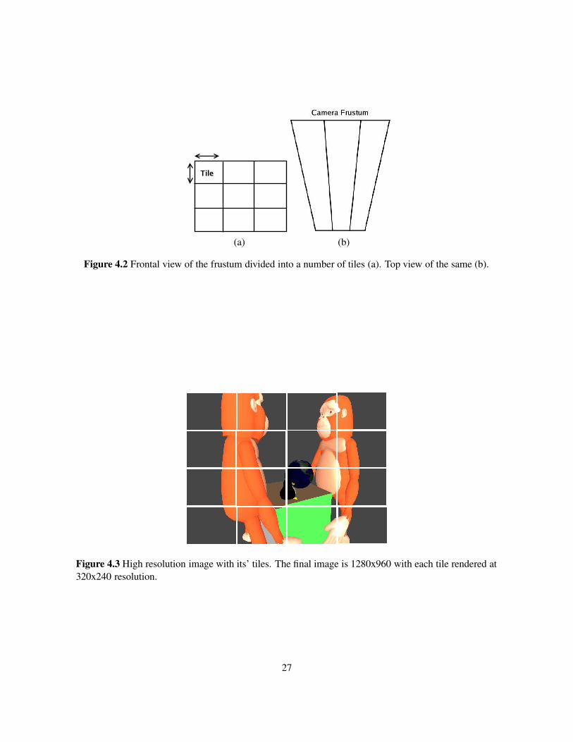
(a) (b)
Figure 4.2 Frontal view of the frustum divided into a number of tiles (a). Top view of the same (b).
Figure 4.3 High resolution image with its’ tiles. The final image is 1280x960 with each tile rendered at320x240 resolution.
27

(a) (b)
Figure 4.4 (a) shows a 640x480 image created with same tile size, (b) is an image of 640x480 renderedusing tiles of 320x240. If we perform image subtraction between these two images, the resulting imageis completly black. This shows that the tiled images generated by our tool are accurate to the pixel level.
Once the symmetric frustum is created, the frustum is divided into parts based on the tile size spec-ified by the user (Figure 4.2). These tiles which are created by dividing the large frustum may benon-symmetric. We assume that the tile size is uniform over all the tiles used to render the final image(Figure 4.3). Our system uses a small tile size (640×480) when tiling is necessary, as it is the minimumsupported resolution on any kinda of hardware.
4.1.2 Validation
In the process of tiling, the same scene is rendered using the same camera with frustum parametersmodified. These frustum parameters are calculated based on the tile position and the tile size. Due tothe process of rasterization involved in rendering pipeline, the pixels on the boundaries may be renderedmore than once in different tiles. Since we have based a constraint on the tile size across the full image,we made sure that there are no such repetitions of pixels at the boundaries. We formulated the followingsimple test to validate our high resolution data:
• Generate 640x480 image using tile size of 320x240 (640x480 image using 4 tiles).
• Generate 640x480 image using tile size of 640x480 (640x480 image using single tile).
• Perform Image Subtraction of the above images.
• If the final image is all black the tiling did not produce any artifacts.
Figure 4.4 shows an example of our validation process. Note that the tiled image shown in the figure isjust to demonstrate that it is a tiled image. It is actually similar to the original image. We have checkedthese results for various resolutions with varying tile sizes.
28

4.2 High Quality
The distinct features that separate real world images from the CG imagery are shadows, illumination etc.DGTk’s in-built renderer supports the default OpenGL features like texture maps, lights and materials.Though these are good enough for generating quite realistic images, the user may have a requirementof even better quality images. Such high quality rendering can be achieved by generating images withbump maps, shadows (soft and hard), Motion blur, etc. Just applying Bump Mapping on a simple sphere(Figure 4.5) can change it’s look drastically. Such advanced features can be supported through ray trac-ing. For this reason we provide an interface in our tool which enables the user to generate the scenedescription for POV-Ray [10].
(a) (b)
Figure 4.5 (a) A Smooth sphere. (b) A Bump Mapped sphere
(a) (b)
Figure 4.6 (a) A simple scene imaged using our OpenGL renderer. (b) Ray Traced image of the samescene.
Persistence of Vison Ray tracer (POV-Ray) is a very popular, free, platform independent ray tracingsoftware which supports all advanced features described above. POV-Ray can generate very high qual-ity images with a color resolution up to 48-bits per pixel. It supports many atmospheric effects likeground-fog, rainbow, etc. Finally the most important feature, it has an easy to use scene descriptionlanguage. Very stunning three-dimensional graphics images can be created by writing just a few linesof text. We exploited this feature for incorporating such high quality rendering into our tool.
29
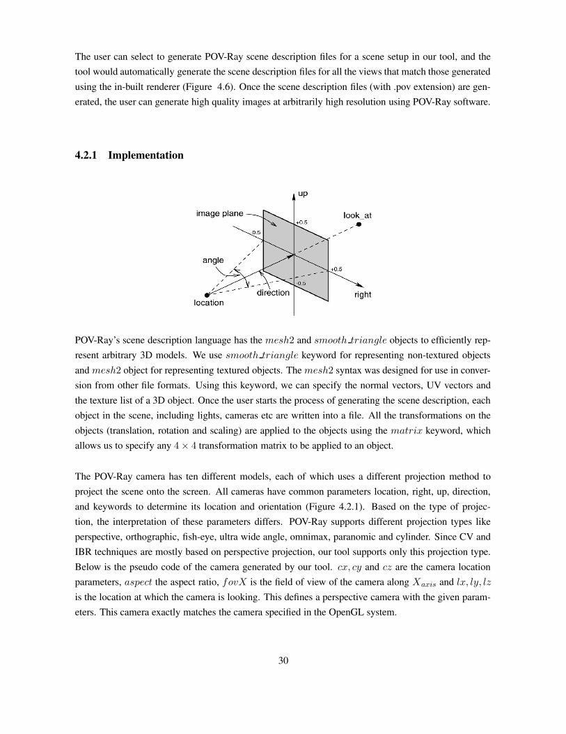
The user can select to generate POV-Ray scene description files for a scene setup in our tool, and thetool would automatically generate the scene description files for all the views that match those generatedusing the in-built renderer (Figure 4.6). Once the scene description files (with .pov extension) are gen-erated, the user can generate high quality images at arbitrarily high resolution using POV-Ray software.
4.2.1 Implementation
POV-Ray’s scene description language has the mesh2 and smooth triangle objects to efficiently rep-resent arbitrary 3D models. We use smooth triangle keyword for representing non-textured objectsand mesh2 object for representing textured objects. The mesh2 syntax was designed for use in conver-sion from other file formats. Using this keyword, we can specify the normal vectors, UV vectors andthe texture list of a 3D object. Once the user starts the process of generating the scene description, eachobject in the scene, including lights, cameras etc are written into a file. All the transformations on theobjects (translation, rotation and scaling) are applied to the objects using the matrix keyword, whichallows us to specify any 4 × 4 transformation matrix to be applied to an object.
The POV-Ray camera has ten different models, each of which uses a different projection method toproject the scene onto the screen. All cameras have common parameters location, right, up, direction,and keywords to determine its location and orientation (Figure 4.2.1). Based on the type of projec-tion, the interpretation of these parameters differs. POV-Ray supports different projection types likeperspective, orthographic, fish-eye, ultra wide angle, omnimax, paranomic and cylinder. Since CV andIBR techniques are mostly based on perspective projection, our tool supports only this projection type.Below is the pseudo code of the camera generated by our tool. cx, cy and cz are the camera locationparameters, aspect the aspect ratio, fovX is the field of view of the camera along Xaxis and lx, ly, lz
is the location at which the camera is looking. This defines a perspective camera with the given param-eters. This camera exactly matches the camera specified in the OpenGL system.
30

camera {
location < cx, cy, cz >
up < 0, 1, 0>
right < -aspect, 0, 0 >
angle fovX
look_at < lx, ly, lz >
}
While specifying the camera parameters for OpenGL api, we use gluPerspective. This takes sixparameters as input namely, field of view along Yaxis (fovY ), aspect ratio (aspect), near plane distance(near) and far plane distance (far). Given these parameters, we calculate the parameters requiredfor the povray camera (i.e, fovX, aspect) using Equation 4.4. Once these values are computed, wesubstitute the value of fovX in camera definition shown above.
height = 2 × (far − near) × tan(π
180× fovY
2)
width = aspect × height
fovX = 2 × 180
π× arctan(
width
(2 × (far − near)))
(4.4)
In our tool we have a default head light (light on the Yaxis). This is also exported into the povray filealong with any additional lights that the user adds to the scene. All the properties (Diffuse, Specular,etc) of the light source are exported to the povray file.
4.3 Camera Calibration
Calibration information of a camera is very vital for many of the CV algorithms which try to estimatethe 3D structure of an object from it’s images. There are algorithms which try to estimate the cameraparameters from the images. Qualitative analysis of such algorithms would be possible if the datasetshave both the images and the calibration information of the camera used for imaging it. In CV literature,the camera is treated as a 3 × 4 matrix transformation which transforms the homogeneous 3D worldcoordinates (P4×1 Matrix) to image coordinates (P ‘3×1). The image of a scene can be calculated usingEquation 4.5.
P ′
3×1 = M3×4 × P4×1 (4.5)
The camera matrix M3×4 consists of two parts, external parameters (position and orientation relativeto the world coordinate system) represented by [R|t]3×4 and the internal parameters (principal point orimage center, focal length and distortion coefficients) represented by K3×3. There are many toolkits[1, 9, 20, 24] that can provide the camera calibration given some images and the corresponding points
31
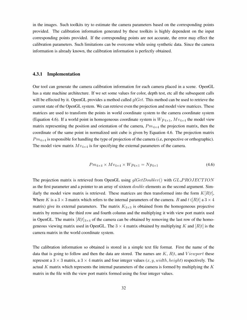
in the images. Such toolkits try to estimate the camera parameters based on the corresponding pointsprovided. The calibration information generated by these toolkits is highly dependent on the inputcorresponding points provided. If the corresponding points are not accurate, the error may effect thecalibration parameters. Such limitations can be overcome while using synthetic data. Since the camerainformation is already known, the calibration information is perfectly obtained.
4.3.1 Implementation
Our tool can generate the camera calibration information for each camera placed in a scene. OpenGLhas a state machine architecture. If we set some values for color, depth test, etc all the subsequent callswill be effected by it. OpenGL provides a method called glGet. This method can be used to retrieve thecurrent state of the OpenGL system. We can retrieve even the projection and model view matrices. Thesematrices are used to transform the points in world coordinate system to the camera coordinate system(Equation 4.6). If a world point in homogeneous coordinate system is Wp4×1, Mv4×4 the model viewmatrix representing the position and orientation of the camera, Pm4×4 the projection matrix, then thecoordinate of the same point in normalized unit cube is given by Equation 4.6. The projection matrixPm4×4 is responsible for handling the type of projection of the camera (i.e, perspective or orthographic).The model view matrix Mv4×4 is for specifying the external parameters of the camera.
Pm4×4 × Mv4×4 × Wp4×1 = Np4×1 (4.6)
The projection matrix is retrieved from OpenGL using glGetDoublev() with GL PROJECTION
as the first parameter and a pointer to an array of sixteen double elements as the second argument. Sim-ilarly the model view matrix is retrieved. These matrices are then transformed into the form K[R|t],Where K is a 3 × 3 matrix which refers to the internal parameters of the camera. R and t ([R|t] a 3 × 4
matrix) give its external parameters. The matrix K3×3 is obtained from the homogeneous projectivematrix by removing the third row and fourth column and the multiplying it with view port matrix usedin OpenGL. The matrix [R|t]3×4 of the camera can be obtained by removing the last row of the homo-geneous viewing matrix used in OpenGL. The 3 × 4 matrix obtained by multiplying K and [R|t] is thecamera matrix in the world coordinate system.
The calibration information so obtained is stored in a simple text file format. First the name of thedata that is going to follow and then the data are stored. The names are K , R|t, and V iewport theserepresent a 3 × 3 matrix, a 3 × 4 matrix and four integer values (x, y, width, height) respectively. Theactual K matrix which represents the internal parameters of the camera is formed by multiplying the K
matrix in the file with the view port matrix formed using the four integer values.
32
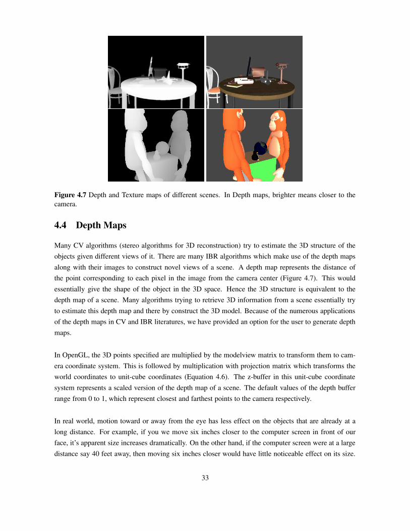
Figure 4.7 Depth and Texture maps of different scenes. In Depth maps, brighter means closer to thecamera.
4.4 Depth Maps
Many CV algorithms (stereo algorithms for 3D reconstruction) try to estimate the 3D structure of theobjects given different views of it. There are many IBR algorithms which make use of the depth mapsalong with their images to construct novel views of a scene. A depth map represents the distance ofthe point corresponding to each pixel in the image from the camera center (Figure 4.7). This wouldessentially give the shape of the object in the 3D space. Hence the 3D structure is equivalent to thedepth map of a scene. Many algorithms trying to retrieve 3D information from a scene essentially tryto estimate this depth map and there by construct the 3D model. Because of the numerous applicationsof the depth maps in CV and IBR literatures, we have provided an option for the user to generate depthmaps.
In OpenGL, the 3D points specified are multiplied by the modelview matrix to transform them to cam-era coordinate system. This is followed by multiplication with projection matrix which transforms theworld coordinates to unit-cube coordinates (Equation 4.6). The z-buffer in this unit-cube coordinatesystem represents a scaled version of the depth map of a scene. The default values of the depth bufferrange from 0 to 1, which represent closest and farthest points to the camera respectively.
In real world, motion toward or away from the eye has less effect on the objects that are already at along distance. For example, if you we move six inches closer to the computer screen in front of ourface, it’s apparent size increases dramatically. On the other hand, if the computer screen were at a largedistance say 40 feet away, then moving six inches closer would have little noticeable effect on its size.
33
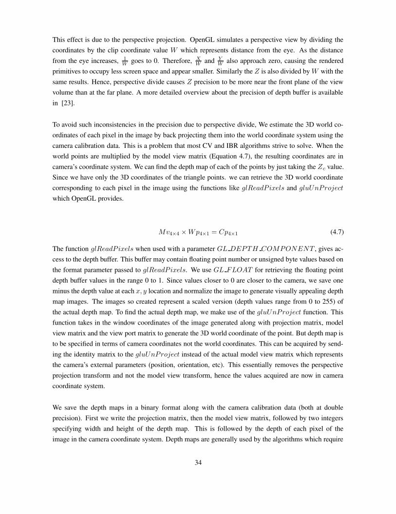
This effect is due to the perspective projection. OpenGL simulates a perspective view by dividing thecoordinates by the clip coordinate value W which represents distance from the eye. As the distancefrom the eye increases, 1
Wgoes to 0. Therefore, X
Wand Y
Walso approach zero, causing the rendered
primitives to occupy less screen space and appear smaller. Similarly the Z is also divided by W with thesame results. Hence, perspective divide causes Z precision to be more near the front plane of the viewvolume than at the far plane. A more detailed overview about the precision of depth buffer is availablein [23].
To avoid such inconsistencies in the precision due to perspective divide, We estimate the 3D world co-ordinates of each pixel in the image by back projecting them into the world coordinate system using thecamera calibration data. This is a problem that most CV and IBR algorithms strive to solve. When theworld points are multiplied by the model view matrix (Equation 4.7), the resulting coordinates are incamera’s coordinate system. We can find the depth map of each of the points by just taking the Zc value.Since we have only the 3D coordinates of the triangle points. we can retrieve the 3D world coordinatecorresponding to each pixel in the image using the functions like glReadP ixels and gluUnProject
which OpenGL provides.
Mv4×4 × Wp4×1 = Cp4×1 (4.7)
The function glReadP ixels when used with a parameter GL DEPTH COMPONENT , gives ac-cess to the depth buffer. This buffer may contain floating point number or unsigned byte values based onthe format parameter passed to glReadP ixels. We use GL FLOAT for retrieving the floating pointdepth buffer values in the range 0 to 1. Since values closer to 0 are closer to the camera, we save oneminus the depth value at each x, y location and normalize the image to generate visually appealing depthmap images. The images so created represent a scaled version (depth values range from 0 to 255) ofthe actual depth map. To find the actual depth map, we make use of the gluUnProject function. Thisfunction takes in the window coordinates of the image generated along with projection matrix, modelview matrix and the view port matrix to generate the 3D world coordinate of the point. But depth map isto be specified in terms of camera coordinates not the world coordinates. This can be acquired by send-ing the identity matrix to the gluUnProject instead of the actual model view matrix which representsthe camera’s external parameters (position, orientation, etc). This essentially removes the perspectiveprojection transform and not the model view transform, hence the values acquired are now in cameracoordinate system.
We save the depth maps in a binary format along with the camera calibration data (both at doubleprecision). First we write the projection matrix, then the model view matrix, followed by two integersspecifying width and height of the depth map. This is followed by the depth of each pixel of theimage in the camera coordinate system. Depth maps are generally used by the algorithms which require
34
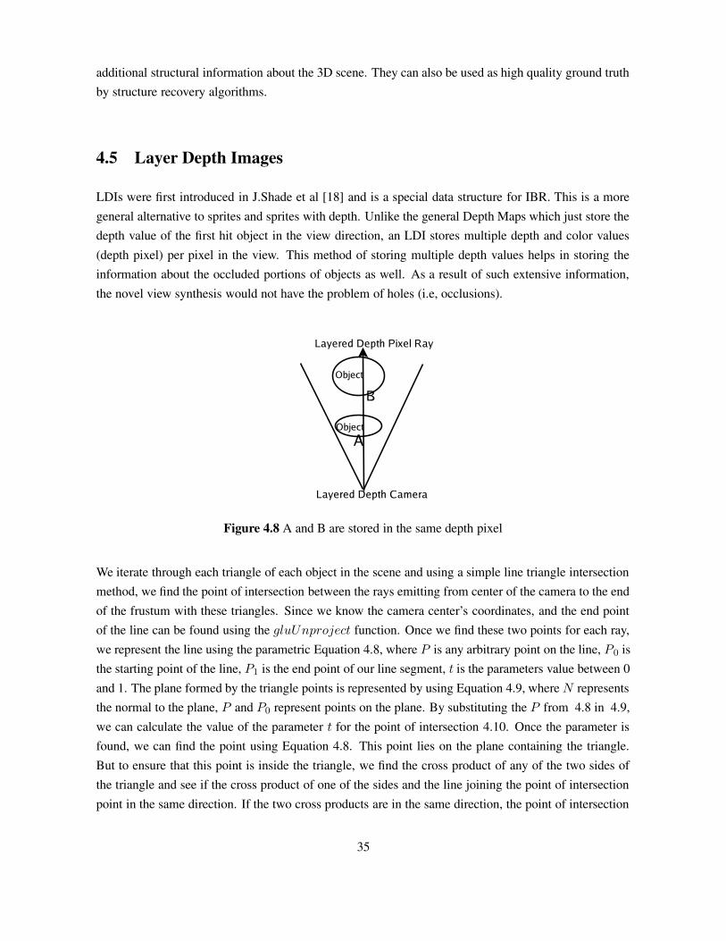
additional structural information about the 3D scene. They can also be used as high quality ground truthby structure recovery algorithms.
4.5 Layer Depth Images
LDIs were first introduced in J.Shade et al [18] and is a special data structure for IBR. This is a moregeneral alternative to sprites and sprites with depth. Unlike the general Depth Maps which just store thedepth value of the first hit object in the view direction, an LDI stores multiple depth and color values(depth pixel) per pixel in the view. This method of storing multiple depth values helps in storing theinformation about the occluded portions of objects as well. As a result of such extensive information,the novel view synthesis would not have the problem of holes (i.e, occlusions).
Figure 4.8 A and B are stored in the same depth pixel
We iterate through each triangle of each object in the scene and using a simple line triangle intersectionmethod, we find the point of intersection between the rays emitting from center of the camera to the endof the frustum with these triangles. Since we know the camera center’s coordinates, and the end pointof the line can be found using the gluUnproject function. Once we find these two points for each ray,we represent the line using the parametric Equation 4.8, where P is any arbitrary point on the line, P0 isthe starting point of the line, P1 is the end point of our line segment, t is the parameters value between 0and 1. The plane formed by the triangle points is represented by using Equation 4.9, where N representsthe normal to the plane, P and P0 represent points on the plane. By substituting the P from 4.8 in 4.9,we can calculate the value of the parameter t for the point of intersection 4.10. Once the parameter isfound, we can find the point using Equation 4.8. This point lies on the plane containing the triangle.But to ensure that this point is inside the triangle, we find the cross product of any of the two sides ofthe triangle and see if the cross product of one of the sides and the line joining the point of intersectionpoint in the same direction. If the two cross products are in the same direction, the point of intersection
35

lies inside the triangle, else it is outside the triangle.
P = P0 + t × (P1 − P0) (4.8)
N.(P − P2) = 0 (4.9)
t =N.(P2 − P0)
N.N(4.10)
We store all the depth and color values that the ray comes across before reaching the end of the frustum(Figure 4.8). Each triangle of the objects is rendered using the camera information, the texture infor-mation and the material information. Once rendered, the color (i.e, material, texture etc) informationcan be retrieved using the glReadP ixels function provided by OpenGL. The points of intersection anddepth information are calculated at double precision. The LDI’s are stored in a binary format. First twointegers width and height. This is followed by width × height number of Layered Depth pixels. Sinceeach Layered depth pixel consists of the R, G, B, A and Z and spatial index, The number of depth pixels(an unsigned int) at each layered depth pixel followed by the depth pixels are written.
4.6 Object Maps
Silhouette is the simplest representation used in cartoons, technical illustrations, architectural designand medical atlases. Complex models can be rendered as silhouette edges for generating non-photo re-alistic images. Silhouettes are useful in applications such as virtual reality and visual hull construction.Many silhouette extraction algorithms try to separate an object from others using segmentation (whenthe background color is not assumed). Silhouette of a model can be either computed in object spaceor in image space. Object space algorithms involve computation of list of silhouette edges for everygiven viewpoint. Screen space or image space algorithms usually involve image processing techniques.Image segmentation is a very important part of solving CV problems like object detection, recognitionand tracking. Real world images are formed by various features like texture, light and other object prop-erties. The CV algorithms would ideally want the parsed image (image decomposed into it’s constituentobjects), but this is a very difficult problem to solve. This is due to the inherent ambiguity in the percep-tion of a 3D scene. If researchers develop a vision algorithm assuming that un-ambiguous segmentationof a scene is available, there is no way to provide real world inputs for testing such algorithms. Weprovide ground truth for this in the form of an object map. Since our tool can generate the object mapsfrom any camera point, it can be used for both object space and image space silhouette extraction.
The object map is defined as an image where each pixel is labeled with a unique id corresponding tothe object that projects to it. i.e, the R, G, B value assigned to each pixel is actually the object id of theobject the pixel belongs to. Our tool generates the Object Maps as PPM images (Figure 4.9). Eachobject is given a unique object id in terms of R, G, B values. This information can be used for testingthe accuracy of image segmentation algorithms.
36

Figure 4.9 Object map and Texture map of a scene
OpenGL has a state machine architecture i.e, if a particular feature is enabled or changed, all the sub-sequent OpenGL calls will be effected by it. For example if the color is set to white using the functionglColor3f(1, 1, 1), all the subsequent primitives will be drawn using white color. For achieving re-alistic rendering, we enable the lighting and texturing features of OpenGL using glEnable functionwith GL TEXTURE 2D and GL LIGHTING respectively. While generating object maps, weprocedurally calculate the object’s id using it’s location in the memory as index. The textures, lightsand material properties are disabled using glDisable function. Once these are disabled, we specify thecolor of each object (R, G, B values for glColor3f ) based on the object id calculated. Since the otherfeatures effecting the color (lights, textures and materials) are disabled, the images rendered have uniquecolor for each object i.e, the object maps. While generating these images, we do not enable any kind ofanti-aliasing. As a result, the images generated have very perfect boundaries i.e, at each pixel location,we can clearly state that it belongs to a particular object, there is no partial presence of objects.
4.7 Alpha Maps
Matting algorithms deal with extraction of a foreground object from the background by estimating thecolor and opacity of the foreground object at each pixel location. Hence these algorithms unlike seg-mentation or silhouette extraction algorithms, require data which has higher precision near the objectboundaries. The image along with this opacity information is typically called a alpha matte or key.Generating alpha matte for foreground objects with thin whisps of fur or hair is a very difficult prob-lem. Fractional opacity values (values between 0 and 1) of the foreground object’s boundaries are tobe produced in these cases. Matting is useful for compositing foreground objects into a new scene.This technique is particularly useful in film and video production for creating special effects. A com-mon method used for extracting the matte is to use a background of known color and make certainassumptions about the colors present in the foreground object. Other approaches attempt to estimate theforeground and background using some standard distributions like Bayesian, Poisson, etc [3, 12, 14].
Our tool provides an option of generating such intermediate values of object’s presence (i.e, a valuebetween 0 and 1). The matting images generated by our tool have R, G, B and A channels unlike the
37

Object maps. The alpha Chanel of a matting image represents the blending parameter for the objects.If we assume that the alpha value of the foreground object at a pixel is α then the alpha value of thebackground object is 1 − α. Hence the alpha value of the object closer to the camera at a pixel locationcan be stored in the alpha Chanel instead of storing both values. This can be considered as a problemsimilar to anti-aliasing an image.
Figure 4.10 Aliased and Anti Aliased Lines
Aliasing is a problem related to the digital displays in today’s computers due to sampling. The currentconsumer technology have a finite memory and processing power. As a result it is not possible to renderenough samples for an acceptable representation of reality. Due to this lack of samples artifacts likejagged, crawling edges and flickering objects are common in current 3D accelerators. These artifactshamper the immersiveness that computer games and 3D applications strive to deliver. To over come theartifacts caused due to aliasing, anti-aliasing algorithms have been developed. Anti-aliasing is basicallythe process of removing the unwanted artifacts like jagged triangle edges. The method commonly usedfor anti-aliasing is to average the color at the borders for smoothening the jaggies caused due to aliasing(Figure 4.10). The color assigned to a boundary pixel during anti aliasing is based on the area of thepixel that a primitive covers(known as coverage). Figure 4.11 shows the partially covered pixels (withdifferent proportions occupied by the polygon). We modified a standard technique called super-samplingused for anti-aliasing, to find the coverage of the pixels at the boundaries of rendered objects. Supersampling involves
• Rendering the whole scene at a larger resolution than the required final output resolution
• Down-sampling the high resolution image to the required resolution.
During down-sampling of the high resolution image, the color of the output pixel in the down-sampledimage is calculated based on the weighted sum of the colors in the corresponding pixels in the highresolution image. Each N × N matrix in the super-sampled image corresponds to a single pixel in thedown-sampled image. For example, if we render the high resolution image at four samples per pixel(i.e, the high resolution image is twice as large as the original image), then the color (Cx,y) of a pixel atx, y in the down sampled image can be calculated by using Equation 4.11 where, ci refers to a unique
38

Figure 4.11 Partially Covered Pixels
color of a pixel in the N × N matrix. N is the number of samples per pixel in x and y direction, nciis
number of pixels in the N × N matrix with color ci.
Cx,y =∑
ci
nci
N2(4.11)
4.7.1 Implementation
The ratio nci
N2 described above gives the coverage of a primitive with color ci in the down-sampled image.Instead of using this ratio for averaging the color for the pixel in down-sampled image, it is used forfinding the alpha value at that pixel location. The id of the object closest to the camera at that pixel isassigned as the color at that pixel. Since object id is required and not the texture information, we render asuper-sampled object map of the scene along with it’s depth map. The dimensions of the super-sampledimage are dependent on the number of samples per pixel and required final image dimensions, it maynot be feasible to render the whole image at once. Hence we use the tiling technique described in section4.1 for rendering the super sampled image. We apply the N × N matrix used for down-sampling thesuper-sampled image on the depth map as well (i.e, for every N × N matrix in object map, a matrix ofsame dimensions and location is considered from the super-sampled depth map). We find the id of theobject closest to the camera based on the depth values obtained from the depth map. Since objects closerto the camera have a lower depth value, we find the location in the matrix with the lowest depth value.Since object maps specify the segmentation of objects perfectly, we use the pixel location correspondingto the lowest depth value in the matrix to find the id of the object closest to the camera (from the objectmap matrix). Once the id of closest object is found, we assign this object id as R, G, B value to thepixel in down-sampled image. The coverage value (i.e, nc
i
N2 ) is assigned to the alpha channel of the samepixel. The following is the modified super sampling algorithm for obtaining the alpha maps with thehelp of object maps.
• Render super-sampled image of the scene based on the number of samples per pixel.
• Read the depth buffer of the super sampled image.
39
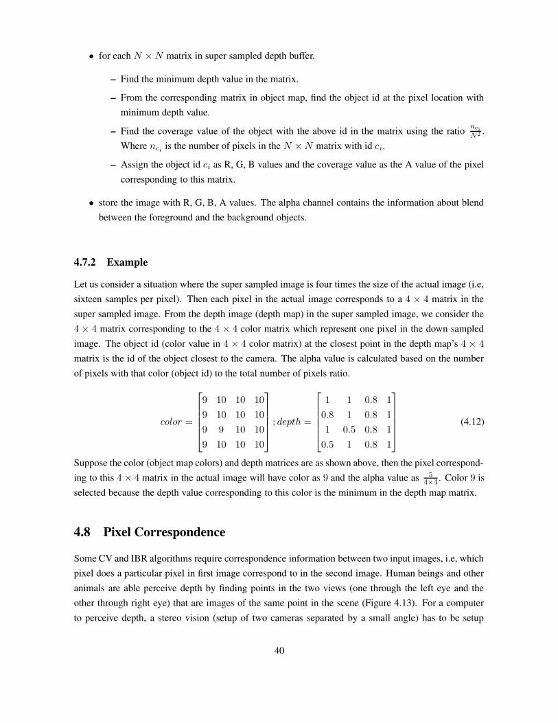
• for each N × N matrix in super sampled depth buffer.
– Find the minimum depth value in the matrix.
– From the corresponding matrix in object map, find the object id at the pixel location withminimum depth value.
– Find the coverage value of the object with the above id in the matrix using the ratio nci
N2 .Where nci
is the number of pixels in the N × N matrix with id ci.
– Assign the object id ci as R, G, B values and the coverage value as the A value of the pixelcorresponding to this matrix.
• store the image with R, G, B, A values. The alpha channel contains the information about blendbetween the foreground and the background objects.
4.7.2 Example
Let us consider a situation where the super sampled image is four times the size of the actual image (i.e,sixteen samples per pixel). Then each pixel in the actual image corresponds to a 4 × 4 matrix in thesuper sampled image. From the depth image (depth map) in the super sampled image, we consider the4 × 4 matrix corresponding to the 4 × 4 color matrix which represent one pixel in the down sampledimage. The object id (color value in 4 × 4 color matrix) at the closest point in the depth map’s 4 × 4
matrix is the id of the object closest to the camera. The alpha value is calculated based on the numberof pixels with that color (object id) to the total number of pixels ratio.
color =
9 10 10 10
9 10 10 10
9 9 10 10
9 10 10 10
; depth =
1 1 0.8 1
0.8 1 0.8 1
1 0.5 0.8 1
0.5 1 0.8 1
(4.12)
Suppose the color (object map colors) and depth matrices are as shown above, then the pixel correspond-ing to this 4 × 4 matrix in the actual image will have color as 9 and the alpha value as 5
4×4. Color 9 is
selected because the depth value corresponding to this color is the minimum in the depth map matrix.
4.8 Pixel Correspondence
Some CV and IBR algorithms require correspondence information between two input images, i.e, whichpixel does a particular pixel in first image correspond to in the second image. Human beings and otheranimals are able perceive depth by finding points in the two views (one through the left eye and theother through right eye) that are images of the same point in the scene (Figure 4.13). For a computerto perceive depth, a stereo vision (setup of two cameras separated by a small angle) has to be setup
40

(a) (b)
(c)
Figure 4.12 (a) The alpha map generated by our tool with object id as the color. (b) The alpha matteof the same image. The grey values at the boundaries represent the fractional opacity of the foregroundobject. (c) Shows the marked area in (b) at a higher scale. It clearly shows the partial opacity at theboundaries of the tree.
41

and the corresponding points are to be found. Unfortunately the reliable identification of correspondingpoints is a very difficult problem. This problem is complex because a point visible in one view may beoccluded in the other or vice versa. For this reason selecting the right points for correspondence is alsoimportant.
The advantage of using the synthetic data is that we have the 3D model of the scene. This informationabout the model can be used to find the points of the 3D point in different views because the cameracalibration information is known. For each view, the 3D point is multiplied by the camera matrix toretrieve the 2D point in the image.
Figure 4.13 The white dots show the corresponding points between the two views.
Our tool can generate both dense correspondences (i.e, for each and every pixel in the first image, wefind the corresponding pixel in the second image) between pairs of images, and sparse correspondences(corresponding points for the selected pixel locations in the first image). The correspondences are storedas floating point disparity to have sub pixel precision. For generating the sparse correspondences, theuser has to select few points in the left (reference) image and our tool generates the corresponding pointsto those points in the right image. We also handle the occlusion based on the camera view. For eachpoint selected in the reference image, the 3D point is found using the gluUnProject function. Oncethe 3D point is found, we use the camera matrix of the destination (right) view to calculate the windowcoordinates of the point using gluProject function. If the z coordinate of the selected point in thedestination view is smaller than or equal to the value in that view’s depth buffer, we have found thecorresponding point. Else the point has been occluded in the new view. Using this method, we can findthe dense correspondences as well.
42

4.9 Dynamic Scenes
With the increase in the availability of cheap hardware for video acquisition, the last few years haveseen a boom in the amount of video content available. Hence the demand for video analysis and sum-marization algorithms has increased multi fold. Many motion tracking and activity detection algorithmshave been developed in the recent years for enhancing the security and search capabilities in videos.Videos are nothing but a sequence of images which capture a real world scene across time. It would bea boon to the researchers in these fields if synthetic videos can be generated for testing their algorithms.Many 3D authoring tools enable users to create complex character, fluid and fur simulations and renderthem as video streams. The major limitation to such tool is the lack of ability to generate the data thatprovides additional information about the structure of the objects in the scene e.g, depth maps, Objectmaps, matting information etc. In some of these tools, the dynamic scenes which require motion of thecamera can only be generated by writing our own scripts. Due to the requirement of such dynamic, andrealistic data, we have added support in our tool for generating Dynamic scenes.
Our tool has the ability to generate dynamic scenes using the information specified by the user in theform of key frames. The user can with ease setup the scene for every key frame and generate the ani-mated sequence of interpolated images. Each key frame specifies the position of all the objects at thatparticular time instant. We have designed a simple structure for saving the details of each key frame. Itcontains the frame number, and each objects rotation, translation and scale properties. These propertiesare interpolated for the (time) frames between the specified key frames. The interpolation of the keyframes is done based on the (time) difference between two consecutive key frames. So if the user wantssome animation to be faster he/she just has to make sure that the difference between two key frames islow.
The position vector of the objects in the scene is interpolated using linear interpolation between theinitial and final positions in the two consecutive key frames. The position of the object in the currentframe is calculated based on the ratio of distances between the current frame to initial key frame and thatbetween initial key frame to the consecutive key frame. If Pcur is the position of the object in the currentframe (Kcur), the object’s position in the initial key frame Kinit is Pinit, position in the consecutive keyframe Kfinal be Pfinal. Equation 4.13 gives the relation between them.
Pcur = Pinit +Pfinal − Pinit
Kfinal − Kinit
× (Kcur − Kinit) (4.13)
Suppose P0 and P10 are positions of an object in frame 0 and frame 10 respectively, the position of thesame object in frame 5 is found using Equation 4.13.
P5 = P0 +P10 − P0
10 − 0× (5 − 0)
43

Where as we use spherical linear interpolation of quaternions for the smooth interpolation of rotations[19]. Quaternions are four dimensional vectors which can be use to represent the angle of rotation andthe axis about which the rotation is to be applied.The advantage of using our tool for generating dynamic data over the other 3D authoring tools is theability to generate additional information for each frame along with the texture map. Very complexscenes with multiple objects crossing each other, scenes with camera motion can be generated alongwith the object maps, depth maps, matting etc (Figure 4.14). Though our tool supports translation,rotation and scaling, it would be hard for a user to create complex animations like people walking etc.For such scenarios, we provide the user with the facility to use the models in formats like MD2, etcwhich store the animation details in the model file.
4.10 Ease of Use
We have designed the graphical user interface for our tool so as to make it easy for the researchers tosetup complex scenes and generate very high quality data. We implemented the GUI using QT. Sinceour target audience are researchers in the fields of CV and IBR, we adopted the graphical user interfaceused by most of the 3D authoring tools (Figure 3.1). Setting up complex scenes that mimic the realworld is possible because the user can import any of the large number of 3D models available on theInternet and place them in appropriate positions by just clicking and dragging the objects to move, rotateor scale them in the 3D space.
The tool currently has support for loading AC3D, 3DS, Md2, and a limited polygonal models of Povrayscene format. We have support for exporting the 3D scene to povray files (.pov) which can be renderedusing a ray tracer like povray. Generating different output formats is as simple as selecting the optionsin check boxes and starting the rendering process (Figure A.1.3). For example, the user can generateimages of arbitrary large resolution (in terms of height and width) by just adjusting the parameters usinga pair of scroll bars (Figure 4.15). The resolution of the image generated in terms of pixel distanceto world distance ratio is displayed in the resolution control interface to enable the user to find theappropriate resolution for his/her experiment.
Dynamic scenes can be created with ease. The user specifies the position, orientation and scale of theobjects in the world at some key frames (key frames in time domain). These key frames represent theevery object’s parameters at that particular time instant. When the user imports 3D models into the tool,they are by default placed at the origin in the world coordinates. Once the user has imported and posi-tioned all the objects (including cameras)in the world scene, the user has to specify the first key frame(frame 0 is to be the first key frame). Subsequently, the user can move, rotate or scale these objects andspecify key frames at any frame (Figure 4.16). A minimum of two key frames with at least one framegap in between them and at least one camera in the world are required for the tool to be able to generate
44
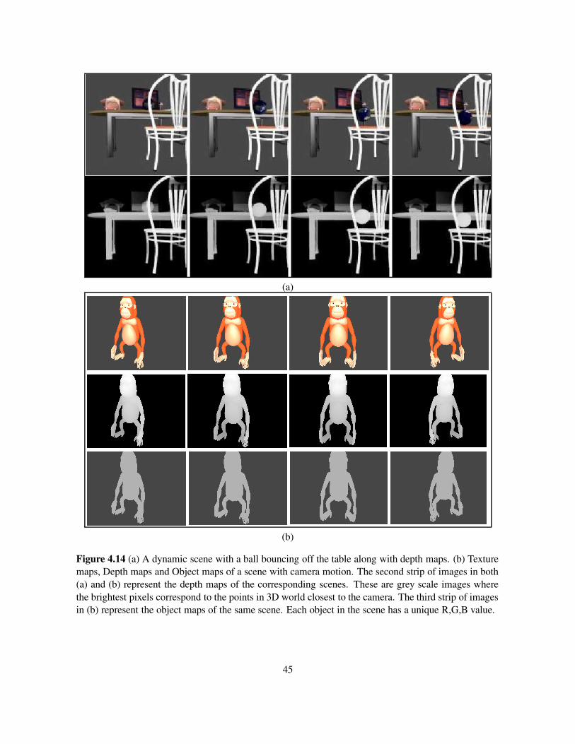
(a)
(b)
Figure 4.14 (a) A dynamic scene with a ball bouncing off the table along with depth maps. (b) Texturemaps, Depth maps and Object maps of a scene with camera motion. The second strip of images in both(a) and (b) represent the depth maps of the corresponding scenes. These are grey scale images wherethe brightest pixels correspond to the points in 3D world closest to the camera. The third strip of imagesin (b) represent the object maps of the same scene. Each object in the scene has a unique R,G,B value.
45
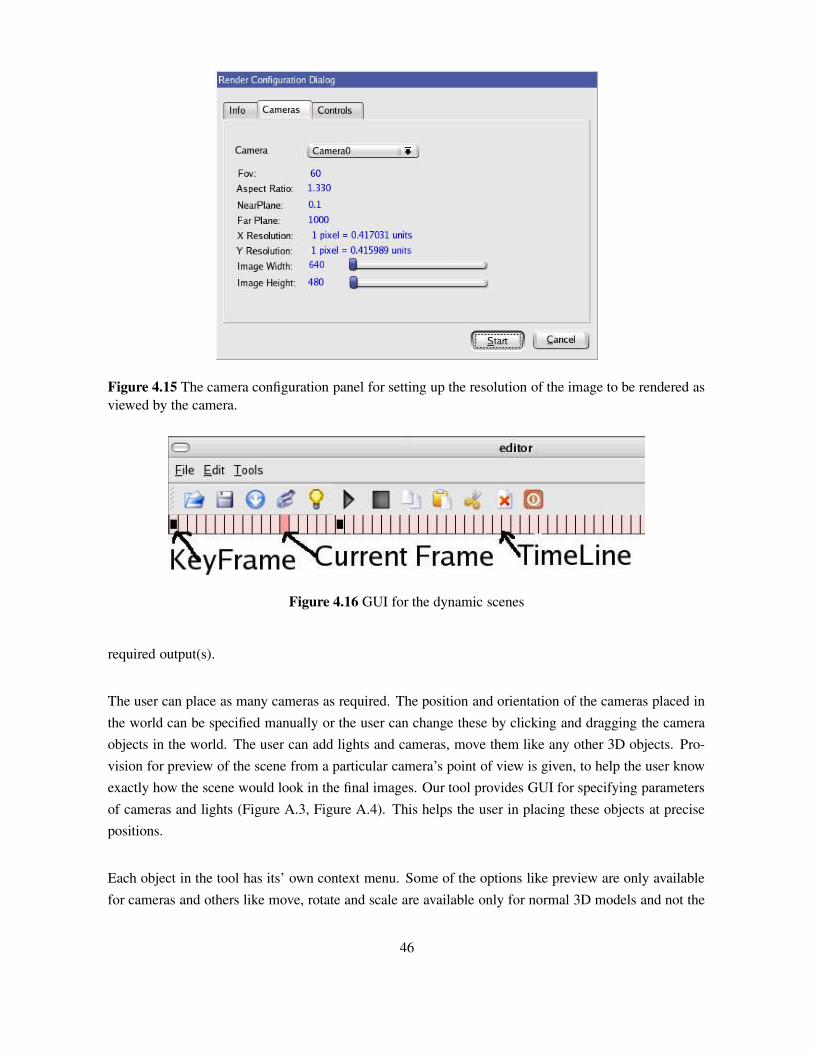
Figure 4.15 The camera configuration panel for setting up the resolution of the image to be rendered asviewed by the camera.
Figure 4.16 GUI for the dynamic scenes
required output(s).
The user can place as many cameras as required. The position and orientation of the cameras placed inthe world can be specified manually or the user can change these by clicking and dragging the cameraobjects in the world. The user can add lights and cameras, move them like any other 3D objects. Pro-vision for preview of the scene from a particular camera’s point of view is given, to help the user knowexactly how the scene would look in the final images. Our tool provides GUI for specifying parametersof cameras and lights (Figure A.3, Figure A.4). This helps the user in placing these objects at precisepositions.
Each object in the tool has its’ own context menu. Some of the options like preview are only availablefor cameras and others like move, rotate and scale are available only for normal 3D models and not the
46

cameras. The user can cut, copy and paste the models imported into the tool. This helps in creatingscenes which require multiple instances of the same 3D model.
47
Chapter 5
Results
DGTk is developed using Qt and OpenGL libraries. We chose to develop our tool using Qt since it caneasily be ported to run on multiple platforms. The library itself is built using a c++ hierarchy and henceenabled us to develop a complete object oriented tool. When ever we were faced with a choice of usingfeatures offered on high end graphics cards and the features supported on most of the graphics cards,we have invariably chosen to use the features supported on most of the graphics hardware. As a resultour tool can run on a vast range of system configurations. The default tile dimensions used in our tiledrenderer is 640 × 480, this resolution is generally supported on almost every system. Our tool gives abetter performance if there is a provision for hardware acceleration in the system. DGTk requires Qt3.3or above and OpenGL libraries to be available on the target system. The goal of developing this toolwas to make synthetic data generation easy, this tool is made available as an Open Source tool. It canbe downloaded from ”http://research.iiit.ac.in/˜vkrishna/editor.tar.gz”.
The highlights of our tool would be the ability to generate data sets with ease and be able to share thedata as well as the means of creating the data. The file format we designed as a part of DGTk can be usedto share complex camera configurations which may be required for some of the CV and IBR algorithms.Our tool provides flexibility to the user in terms of the types of 3D models that can be imported, to createthe scenes. DGTk is a vision aware tool; It can generate various representations of a 3D scene like depthmaps, object maps, point correspondences etc which are very valuable for CV and IBR researchers. Itwould be the first time where the object segmentation and the matte information are provided as groundtruth data in the form of alpha maps. Our tool presents the user with one of the easiest interfaces forcreating dynamic scenes. This helps in creating large amounts of different representations of dynamicdata along with the actual images. Another important feature of our tool would be it’s object orientedframe of design. The over all UI of our tool is similar to that of some of the standard 3D authoring tools.This makes our tool easy to master. We have taken care to make sure that the tool is easy to extend forsupporting new representations and file formats.
48
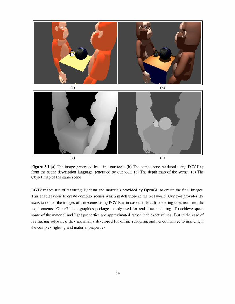
(a) (b)
(c) (d)
Figure 5.1 (a) The image generated by using our tool. (b) The same scene rendered using POV-Rayfrom the scene description language generated by our tool. (c) The depth map of the scene. (d) TheObject map of the same scene.
DGTk makes use of texturing, lighting and materials provided by OpenGL to create the final images.This enables users to create complex scenes which match those in the real world. Our tool provides it’susers to render the images of the scenes using POV-Ray in case the default rendering does not meet therequirements. OpenGL is a graphics package mainly used for real time rendering. To achieve speedsome of the material and light properties are approximated rather than exact values. But in the case ofray tracing softwares, they are mainly developed for offline rendering and hence manage to implementthe complex lighting and material properties.
49

(a) (b)
(c) (d)
Figure 5.2 (a) A scene with trees and grass which have thin polygons. This scene is an ideal case fortesting the alpha maps generated by our tool. (b) Alpha matte corresponding to the scene. The alphamap shows the partial opacity of the object at the boundaries. This is essential for testing some of thematting algorithms. (c) Depth maps describe the distance of each pixel in the image from the camerain the camera coordinates. We have inverted the actual depth map values to generate visually appealingimages. The brighter pixels correspond to the pixels closer to the camera. (d) The Object map of suchcomplex scenes are very useful for testing segmentation algorithms. Each object in the 3D scene isgiven a unique object id. Every pixel in the image is assigned a R,G,B value corresponding to the id ofthe Object which projects to it.
50
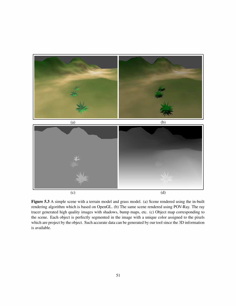
(a) (b)
(c) (d)
Figure 5.3 A simple scene with a terrain model and grass model. (a) Scene rendered using the in-builtrendering algorithm which is based on OpenGL. (b) The same scene rendered using POV-Ray. The raytracer generated high quality images with shadows, bump maps, etc. (c) Object map corresponding tothe scene. Each object is perfectly segmented in the image with a unique color assigned to the pixelswhich are project by the object. Such accurate data can be generated by our tool since the 3D informationis available.
51

Figure 5.4 This figure shows six frames of a dynamic scene created using our tool. The actual sequencehas fifty four frames. The major advantage of our tool is that all the representations can be generated forevery frame of the dynamic scene. This is not possible in most of the available systems. The first strip ofimages shows the texture (actual image) of the scene through a camera. The second strip of images arethe depth maps of the corresponding scenes. The third strip of images are the object map representationof the scene. This is the first time where users can generate different representations of complex sceneswith ease.
52
Chapter 6
Conclusions and Future Work
In this thesis, we have presented a versatile toolkit to produce high quality synthetic data for testingComputer Vision and Image Based Rendering Algorithms. We have described why such a tool is nec-essary for improving the research in these areas. Various formats commonly used as datasets for testingCV and IBR algorithms have been implemented in our tool. The major contribution of our work is inthe creation of a tool which enables the researchers to create their own datasets with ease. We have de-signed the tool so as to enable sharing of datasets among the researchers. Our tool has been successfullyused for testing some of the algorithms developed at our lab. The idea behind development of such atool goes beyond just creating datasets for CV and IBR algorithms. The major impact of this tool ison the time spent on creating the datasets for testing such algorithms. The tool itself is not limited togenerating only data which can be used in CV and IBR algorithms. Our tool can easily be extended tosupport more input formats or output formats. It is intended to make our tool available freely along withsome datasets for the community to use.
6.1 Future Work
As the developments in the areas of CV and IBR are at a high pace, the tool has to be up-to date to beable to generate high resolution data which can be used to compare state of the art algorithms. Thereare a lot of aspects in our tool that require attention in the future. With the increase in the power of thegraphics hardware, the point based representations have gained popularity in the fields of IBR. Supportfor these representations would be a critical development for our tool.
DGTk currently supports generating images at various resolutions. The idea behind supporting suchfunctionality was to enable users to test the robustness of their algorithms to changes in resolutions.Though this is enough under the current scenario, it may be useful to be able to add procedural orrandom noise to the data generated. Support for noise models in the data generated is another criticalfeature to be added in future.
53

6.2 Conclusions
We created a tool which solves the problem of lack of good tools for generating synthetic data sets fortesting CV and IBR algorithms. The tool not only reduces the time spent by researchers in creating datasets, but also enables them to share the data in a standard format. The problem with using data createdyears ago is the that it may be inadequate to test the current state of the art high quality algorithms. Ourtool enables researchers to over come this problem by providing a scene description format which canbe used to render data again at any required resolution or quality. This tool has proved to be helpfulfor testing algorithms which are in development stage. Since it can generate any required ground truthdata. For example, if a motion tracking algorithm or alpha matte algorithm assumes it has a perfectlysegmented image, the user can use the object maps generated by our tool as the segmentation. Thesegmentation provided by our tool is perfect and can hence be used as a benchmark for comparision ofnew algorithms.
6.3 Summary
Due to increasing demand for high quality CV and IBR algorithms, high quality data sets which candifferenciate among the best performing algorithms is very desirable. Such data is very difficult and timeconsuming in real world. The performance of these algorithms on synthetic data is a good indicator oftheir performance on the real world data. Hence high resolution synthetic data is required. Researchersand research labs spend a lot of resources in the creation of data sets and data generation tools for testingtheir algorithms. It may not be feasible to extend such tools, since they are generally developed forgenerating a single data representation. We tried to address this problem by creating a data generationtool which is easily extendable and is easy to use for generating standard data like depth maps, alphamaps, object maps, etc. This tool makes sharing of data possible in the research community.
54

Appendix A
User Manual
DGTk is a vison aware tool which can generate depth maps, object maps, point correspondences, etcwhich are very valuable for CV and IBR researchers. We have designed the tool to be very flexible,versatile and easy to extend. The reasons for developing a separate tool for data generation ratherthan extending already available tools include, (1) Lack of availability of information about internalrepresentation of data in such tools, (2) Very complex and difficult to learn interfaces, (3) Require un-intuitive extensions to tools due to their internal architectures. (4) Lack of good documentation forextending such tools. In this chapter we intend to introduce various features of our tool to the users.
A.1 Main Window
The GUI of our tool is similar to that of a standard 3D authoring tool. The main window that appearsonce the application launches, contains a menu bar and a tool bar. The menu has the standard elementslike File, Edit and Tools. These three menus provide all the functionality that is needed for the userin terms of data generation. This is another major advantage of using our tool. The user does not haveto spend hours trying to figure out which item performs what function. The menu items contain thestandard images depicting the operation to be performed by that particular menu item (Figure A.1).
(a) (b) (c)
Figure A.1 (a) File menu, (b) Edit menu and (c) Tools menu. Each operation has it’s own standard iconbeside the operation.
55
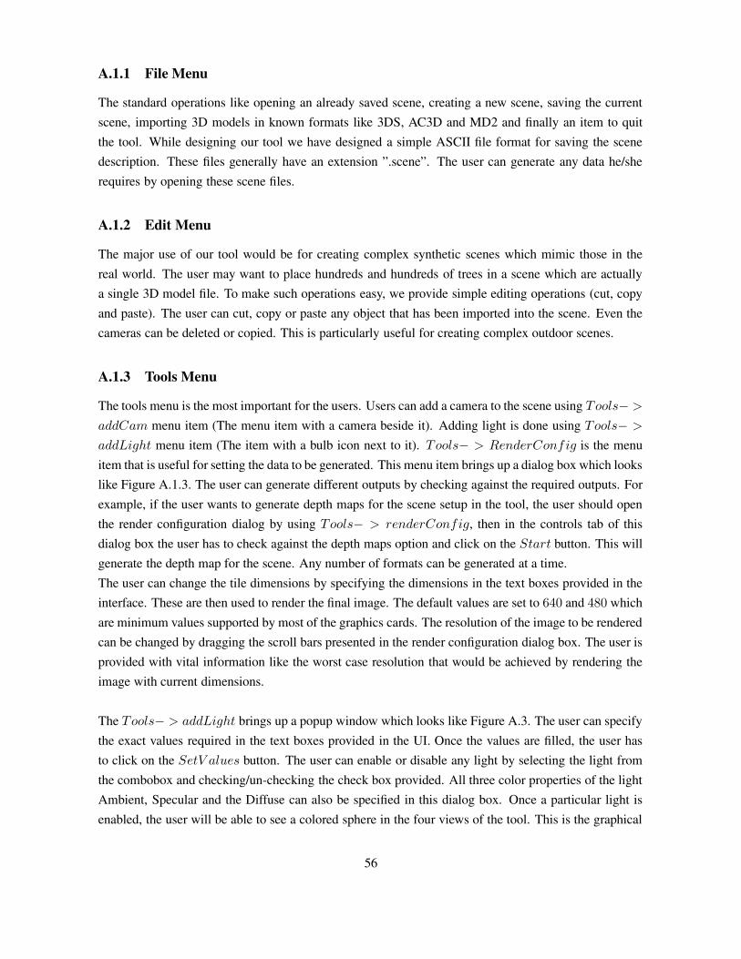
A.1.1 File Menu
The standard operations like opening an already saved scene, creating a new scene, saving the currentscene, importing 3D models in known formats like 3DS, AC3D and MD2 and finally an item to quitthe tool. While designing our tool we have designed a simple ASCII file format for saving the scenedescription. These files generally have an extension ”.scene”. The user can generate any data he/sherequires by opening these scene files.
A.1.2 Edit Menu
The major use of our tool would be for creating complex synthetic scenes which mimic those in thereal world. The user may want to place hundreds and hundreds of trees in a scene which are actuallya single 3D model file. To make such operations easy, we provide simple editing operations (cut, copyand paste). The user can cut, copy or paste any object that has been imported into the scene. Even thecameras can be deleted or copied. This is particularly useful for creating complex outdoor scenes.
A.1.3 Tools Menu
The tools menu is the most important for the users. Users can add a camera to the scene using Tools− >
addCam menu item (The menu item with a camera beside it). Adding light is done using Tools− >
addLight menu item (The item with a bulb icon next to it). Tools− > RenderConfig is the menuitem that is useful for setting the data to be generated. This menu item brings up a dialog box which lookslike Figure A.1.3. The user can generate different outputs by checking against the required outputs. Forexample, if the user wants to generate depth maps for the scene setup in the tool, the user should openthe render configuration dialog by using Tools− > renderConfig, then in the controls tab of thisdialog box the user has to check against the depth maps option and click on the Start button. This willgenerate the depth map for the scene. Any number of formats can be generated at a time.The user can change the tile dimensions by specifying the dimensions in the text boxes provided in theinterface. These are then used to render the final image. The default values are set to 640 and 480 whichare minimum values supported by most of the graphics cards. The resolution of the image to be renderedcan be changed by dragging the scroll bars presented in the render configuration dialog box. The user isprovided with vital information like the worst case resolution that would be achieved by rendering theimage with current dimensions.
The Tools− > addLight brings up a popup window which looks like Figure A.3. The user can specifythe exact values required in the text boxes provided in the UI. Once the values are filled, the user hasto click on the SetV alues button. The user can enable or disable any light by selecting the light fromthe combobox and checking/un-checking the check box provided. All three color properties of the lightAmbient, Specular and the Diffuse can also be specified in this dialog box. Once a particular light isenabled, the user will be able to see a colored sphere in the four views of the tool. This is the graphical
56

Figure A.2 The render configuration panel. This is where the user selects what outputs are to be gener-ated by the tool.
representation of the light and can be moved and placed at any desired location just like any other objectimported into the tool.
Figure A.3 The configuration dialogs for placing lights at specific locations
The camera dialog (Figure A.4) can be accessed by using Tools− > AddCam item in the menu. Thecamera center can be specified in the 3D world cordinates using the text boxes in the UI. Simillarly thelook at and orientation of the camera can also be specified. The field of view, aspect ratio, near planeand far plane are also specified using the same UI. The user can directly preview the camera’s view by
57
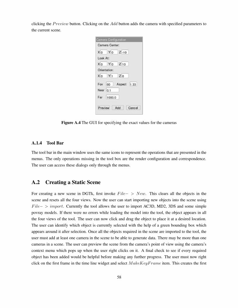
clicking the Preview button. Clicking on the Add button adds the camera with specified parameters tothe current scene.
Figure A.4 The GUI for specifying the exact values for the cameras
A.1.4 Tool Bar
The tool bar in the main window uses the same icons to represent the operations that are presented in themenus. The only operations missing in the tool box are the render configuration and correspondence.The user can access these dialogs only through the menus.
A.2 Creating a Static Scene
For creating a new scene in DGTk, first invoke File− > New. This clears all the objects in thescene and resets all the four views. Now the user can start importing new objects into the scene usingFile− > import. Currently the tool allows the user to import AC3D, MD2, 3DS and some simplepovray models. If there were no errors while loading the model into the tool, the object appears in allthe four views of the tool. The user can now click and drag the object to place it at a desired location.The user can identify which object is currently selected with the help of a green bounding box whichappears around it after selection. Once all the objects required in the scene are imported to the tool, theuser must add at least one camera in the scene to be able to generate data. There may be more than onecameras in a scene. The user can preview the scene from the camera’s point of view using the camera’scontext menu which pops up when the user right clicks on it. A final check to see if every requiredobject has been added would be helpful before making any further progress. The user must now rightclick on the first frame in the time line widget and select MakeKeyFrame item. This creates the first
58

key frame of our scene. For creating a static scene the user should now left click on the third frame inthe time line widget, then right click and make it a key frame. If the user desires, he/she can save itusing File− > Save. Now that the scene is setup, the user can launch the render configuration dialogusing Tools− > RenderConfig and start rendering the required representations of the scene.
A.3 Creating a Dynamic Scene
Once the first key frame is created after a scene is set (i.e, the first frame in the time line widget ismade as a key frame), The user can create a dynamic scene quite easily. We shall show how to createa dynamic scene which has simple linear motion of one or more objects. Now that the first key frameis set, left click on a frame some ten frames away from the first frame. Move the objects in the sceneby clicking and dragging them to a new position. Right click on the same frame again and make it akey frame. This results in a scene which is nine frames long and has moving objects. The user can alsocreate dynamic scenes with rotating objects. For this, instead of dragging the objects, right click on theobjects, select the rotate item in the context menu and move the move a little to see the rotation of theobject. Once the object reaches the desired orientation, make the second key frame. This process canbe used to create as many key frames as required. The important point to note while creating a scene isto import all the required objects before making the first key frame.
59

Appendix B
Scene File Format
B.1 Introduction
The major hurdle for most of the researchers while using synthetic data is that the tools developed fordata generation are not scalable. Such tools cannot be used by other researchers to generate data withsome other scene setup. This limits the data that can be shared among the researchers. The datasetscannot be changed very easily. Some researchers have tried to over come this hurdle by specifying theconstraints and methods to be used for acquiring the datasets [17]. A lot of time goes into configuringthese tools to generate the data which is acceptable for testing the algorithms. If such data generationtools provide some method of sharing the scene created for generating the datasets, the users would beable to make minor modifications like changing the objects in the scene and use the same configurationof cameras, lights etc to generate new datasets.
Many ray tracing softwares support very powerful high level scene description languages. Users canrepresent complex scenes which mimic the real world with ease. These scene description languagesare generally in ASCII format (human readable format), but they are very complex to understand at thefirst look. Since complex mesh objects require a large number of vertexes and texture coordinates, theamount of data that is present in these scene description files cannot be understood without the help ofsome kind of scene graph editor. Many 3D authoring tools have the capability to generate the scene de-scription of the scenes setup using them. As stated in the earlier chapters, Though such tools have beenvery effective in generating high resolution images with photo realistic quality, It is very unintuitive toextend these softwares to generate any other representation which may be useful for creating datasets,crucial for testing CV and IBR algorithms.
A data generation tool would require a more robust and abstract representation of the world. A repre-sentation that can be extended to incorporate any new extensions made to the tool. Care has to be takennot to make such scene files human readable and at the same time extend-able. Human readability ofthe files is an important since it enables the user to make modifications to the scene file to match his/her
60
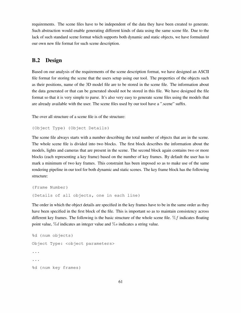
requirements. The scene files have to be independent of the data they have been created to generate.Such abstraction would enable generating different kinds of data using the same scene file. Due to thelack of such standard scene format which supports both dynamic and static objects, we have formulatedour own new file format for such scene description.
B.2 Design
Based on our analysis of the requirements of the scene description format, we have designed an ASCIIfile format for storing the scene that the users setup using our tool. The properties of the objects suchas their positions, name of the 3D model file are to be stored in the scene file. The information aboutthe data generated or that can be generated should not be stored in this file. We have designed the fileformat so that it is very simple to parse. It’s also very easy to generate scene files using the models thatare already available with the user. The scene files used by our tool have a ”.scene” suffix.
The over all structure of a scene file is of the structure:
(Object Type) (Object Details)
The scene file always starts with a number describing the total number of objects that are in the scene.The whole scene file is divided into two blocks. The first block describes the information about themodels, lights and cameras that are present in the scene. The second block again contains two or moreblocks (each representing a key frame) based on the number of key frames. By default the user has tomark a minimum of two key frames. This constraint has been imposed so as to make use of the samerendering pipeline in our tool for both dynamic and static scenes. The key frame block has the followingstructure:
(Frame Number)
(Details of all objects, one in each line)
The order in which the object details are specified in the key frames have to be in the same order as theyhave been specified in the first block of the file. This is important so as to maintain consistency acrossdifferent key frames. The following is the basic structure of the whole scene file. %f indicates floatingpoint value, %d indicates an integer value and %s indicates a string value.
%d (num objects)
Object Type: <object parameters>
...
...
%d (num key frames)
61

%d (frame number)
<object parameters>
...
...
%d (frame number)
...
...
The first line in the file describes the number of objects present in the scene. The lines following thisnumber are the details about each object. We have defined special tags for each object type describingthe kind of object that follows, to make the file more readable and to perform extra operations on thescene file. For example, the camera object has the location and the look at values. These values arerepresented by two objects and hence require the tool to read another object in the file when it findsa camera object. This is a simple strategy we have adopted to ensure easy extendability of the tool tosupport different input formats. There are some predefined object types that are currently supported inour file format. glObject Light refers to light objects, glObject AC to represent an AC3D file or apovray scene file, glObject Camera for specifying the camera details, glObject 3DS for 3ds objectsand glObject Md2 for md2 objects. Following this information is the number of key frames in thescene. This gives the total number of key frames that have been setup by the user in the scene. Whatfollows is a sequence of frame number and object details blocks. Each of these are important buildingblocks of the dynamic scene to be generated using the tool. Each key frame represents a time instant.For all the time instances in between these key frames, the tool has to interpolate the object propertiesbased on their values at the key frames.
The file format does not have any limitation on the number of objects of any type that can be placedin the scene file. Many objects, cameras, light sources can be present in a single scene file. Due to thefreedom over the number of objects (cameras especially) users will be able to create complex cameraconfigurations like hemisphere or circular etc. Figure B.2 is an example of complex camera setupspossible using our tool by specifying the cameras externally in the scene file. This is an importantfeature because specifying parameters of each camera in the GUI can be inconvenient. Since we areusing OpenGL for rendering purposes, the common number of lights supported on most of the graphicshardware is eight. This is the current limitation on the number of lights that can be put in a scene.
B.3 Implementation
We have implemented a simple parser for parsing the input scene files and setting up the scenes in thetool. The integer value in the first line is read and based on this number, the rest of the data is loaded. As
62

(a) (b)
Figure B.1 (a) A semi circular setup of 48 cameras for acquiring the images around the face model. Thecameras in this scene were added not using the tool but through another program which generated thecenter and look at points of all the 48 cameras. Such large number of cameras cannot be added manuallyinto a scene as it is very time consuming process. (b) Images of some of the views of the camera setup.
Figure B.2 An outdoor scene created and rendered using our data generation tool. This scene hasmultiple objects and a single camera unlike the above figure.
63

stated before every line describes an object type followed by the details about that particular object. Thetokens describing the object id are used for creating an instance of the corresponding class implementedfor loading that object type. For example, we have implemented a class called acObject which inheritsa base class called glObject, for loading the ac3d models. Similarly we have implemented md2Object,Model 3DS for loading MD2 and 3DS models respectively. While loading the scene files, the toolloads all the key frames in the scene. These key frames are shown in the time line just like they werewhen the actual scene was created. While loading the information about the key frames we assume thatthe order in which the object details appear is same as the order in which the object model details appearin the first block of the scene file.
The following is an example scene file:
3
glObject_AC: tuxedo.ac
glObject_AC: world.ac
glObject_Camera: ( 60, 0.1, 1000, 1.33 )
[ 2.45 0 -7.24999, -4.5 0 4.09998, 0 1 0 ]
2
0
< 0 0 0 > { 1.00 , < 0, 0, 0 > }
< 0 0 0 > { 1.00 ,< 0, 0, 0 > }
< 2.45 0 -7.24999 > { 1.0000 ,< 0, 0, 0 > }
< -4.5 0 4.09998 > { 1.00000 ,< 0, 0, 0 > }
2
< 0 0 0 > { 1.00 , < 0, 0, 0 > }
< 0 0 0 > { 1.00 ,< 0, 0, 0 > }
< 2.45 0 -7.24999 > { 1.0000 ,< 0, 0, 0 > }
< -4.5 0 4.09998 > { 1.00000 ,< 0, 0, 0 > }
The scene file shown above describes a scene with two 3d models (ac3d files tuxedo.ac and world.ac)along with a camera. During design of our tool, we have combined the rendering pipeline for both staticand dynamic scenes. Due to this design methodology, every scene file should have two key frames eventhough there is no motion in the scene. The above scene file has two key frames one at frame 0 andanother at frame 2. You will observe that there is no change in the position of the objects in the twoframes.
64

Publications
Our paper describing this work got accepted in International Conference on Visual Information En-gineering (VIE 2006). We plan to update the tool and present it as a journal at Journal of Graphics Tools(jgt).
65
Bibliography
[1] Jean-Yves Bouguet. A matlab toolkit for camera calibration.http://www.vision.caltech.edu/bouguetj/calib doc/.
[2] Raffaele Cappelli. Sfinge: an approach to synthetic fingerprint generation. In International Work-shop on Biometric Technologies (BT2004), pages 147–154, Calgary, Canada, 2004.
[3] Yung-Yu Chuang, Brian Curless, David H. Salesin, and Richard Szeliski. A bayesian approach todigital matting. In Proceedings of IEEE CVPR 2001, volume 2, pages 264–271. IEEE ComputerSociety, December 2001.
[4] Winfried A. Fellenz, Karsten Schluns, Andreas Koschan, and Matthias Teschner. An active visionsystem for obtaining high resolution depth information. In CAIP ’97: Proceedings of the 7thInternational Conference on Computer Analysis of Images and Patterns, pages 726–733, London,UK, 1997. Springer-Verlag.
[5] James D. Foley, Andries van Dam, Steven K. Feiner, and John F. Hughes. Computer graphics:principles and practice (2nd ed.). Addison-Wesley Longman Publishing Co., Inc., Boston, MA,USA, 1990.
[6] Eric Haines. Free ray tracer summary in ray tracing news, light makes right. ftp://ftp-graphics.stanford.edu/pub/Graphics/RTNews/html/rtnv6n3.html#art4, September 28, 1993.
[7] T. Igarashi, T. Moscovich, and J. F. Hughes. Spatial keyframing for performance-driven animation.In SCA ’05: Proceedings of the 2005 ACM SIGGRAPH/Eurographics symposium on Computeranimation, pages 107–115, New York, NY, USA, 2005. ACM Press.
[8] Takeo Igarashi, Satoshi Matsuoka, and Hidehiko Tanaka. Teddy: a sketching interface for 3dfreeform design. In SIGGRAPH ’99: Proceedings of the 26th annual conference on Com-puter graphics and interactive techniques, pages 409–416, New York, NY, USA, 1999. ACMPress/Addison-Wesley Publishing Co.
[9] Jonathan Merritt. Camera calibration for blender camera (python script for extending blender).http://www.warpax.com/pytsai/index.html.
66

[10] Persistance of Vision Raytracer Pty.Ltd. Pov-ray. http://www.povray.org.
[11] Kapil Hari Paranjape. How to make a stereogram with GIMP, Blender and stereograph.http://linuxgazette.net/104/kapil.html.
[12] Patrick Perez, Michel Gangnet, and Andrew Blake. Poisson image editing. ACM Trans. Graph.,22(3):313–318, 2003.
[13] Nicholas Phillips. Cheap 3d scanning (for blender). http://sans.chem.umbc.edu/∼ nicholas/blender/3dscan/.
[14] M.A Ruzon and C. Tomasi. Alpha estimation in natural images. In CVPR, pages 1018–1025,2000.
[15] Daniel Scharstein and Richard Szeliski. A taxonomy and evaluation of dense two-frame stereocorrespondence algorithms. International Journal of Computer Vision, 47(1-3):7–42, 2002.
[16] Daniel Scharstein and Richard Szeliski. High-accuracy stereo depth maps using structured light.In Computer Vision and Pattern Recognition (CVPR), pages 195–202, 2003.
[17] Steven M. Seitz, Brian Curless, James Diebel, Daniel Scharstein, and Rick Szeliski. A compari-son and evaluation of multi-view stereo reconstruction algorithms. Computer Vision and PatternRecognition (CVPR), 2006.
[18] Jonathan Shade, Steven Gortler, Li wei He, and Richard Szeliski. Layered depth images. InSIGGRAPH ’98: Proceedings of the 25th annual conference on Computer graphics and interactivetechniques, pages 231–242, New York, NY, USA, 1998. ACM Press.
[19] Ken Shoemake. Animating rotation with quaternion curves. In SIGGRAPH ’85: Proceedingsof the 12th annual conference on Computer graphics and interactive techniques, pages 245–254,New York, NY, USA, 1985. ACM Press.
[20] Roger Tsai. An efficient and accurate camera calibration technique for 3d machine vision. IEEEConference on Computer vision and Pattern Recognition, Miami Beach, FL, pages 364–374, 1986.
[21] Carnegie Mellon University (CMU) Computer vision Test Images.http://www.cs.cmu.edu/∼ cil/v-images.html.
[22] Mason Woo, Davis, and Mary Beth Sheridan. OpenGL Programming Guide: The Official Guideto Learning OpenGL, Version 1.2. Addison-Wesley Longman Publishing Co., Inc., Boston, MA,USA, 1999.
[23] Richard S Wright and Benjamin Lipchak. OpenGL SuperBible (3rd Edition). Sams, Indianapolis,IN, USA, 2004.
[24] Zhengyou Zhang. A flexible new technique for camera calibration. IEEE Trans. Pattern Anal.Mach. Intell., 22(11):1330–1334, 2000.
67


![Unit-Based Team Toolkit - Labor Management Partnership · INTRODUCTION | UNIT-BASED TEAM TOOLKIT Unit-Based Team Toolkit | [ i.1] Introducing the UBT Toolkit Purpose of This Toolkit](https://static.fdocuments.us/doc/165x107/5ed0a8550b370e0edc660352/unit-based-team-toolkit-labor-management-partnership-introduction-unit-based.jpg)