DG Diagnostics (OBDII) - Dearborn Group, Inc. · 2. DG Diagnostics (OBDII) and DG Diagnostics...
24
DG Diagnostics (OBDII) OBDII Diagnostic Tool User Manual for Version 1.01 Document Revision 1.00.7 Document Date: 05/27/2014 © 2013-2014 Dearborn Group, Inc.
-
Upload
nguyendung -
Category
Documents
-
view
230 -
download
1
Transcript of DG Diagnostics (OBDII) - Dearborn Group, Inc. · 2. DG Diagnostics (OBDII) and DG Diagnostics...
DG Diagnostics (OBDII) OBDII Diagnostic Tool
User Manual for Version 1.01 Document Revision 1.00.7 Document Date: 05/27/2014 © 2013-2014 Dearborn Group, Inc.
Page 2 of 24 © 2013-2014 Dearborn Group, Inc.
Permission is granted to copy any or all portions of this manual, provided that such copies are for use with the Dearborn Group, Inc. products and that “© 2013-2014 Dearborn Group, Inc.” (herein referred to as “Dearborn Group”, “DG”, or “DG Technologies”), remains on all copies.
The DG Diagnostics (OBDII) software is copyrighted. Permission is granted to copy this software for back-up purposes only. This software works only in conjunction with Dearborn Group, Inc. SAE J2534-compliant devices. Any attempt to modify the software, or PC environment, so that this program would connect and use a non-DG J2534 device will be considered a breach of the programs’ copyright.
I M P O R T A N T
To ensure your success with this product, it is essential that you read this document carefully before using the hardware. Damage caused by misuse of the hardware is not covered under warranty.
When using this manual, please remember the following:
This manual may be changed, in whole or in part, without notice.
DG Technologies assumes no responsibility for any damage resulting from the use of this software.
Specifications presented herein are provided for illustration purposes only and may not accurately represent the latest revision of software.
No license is granted, by implication or otherwise, for any patents or other rights of Dearborn Group, Inc. or of any third party.
The “DG” square logo is a registered trademark of Dearborn Group, Inc. Other products that may be referenced in this manual are trademarks of their respective manufacturers.
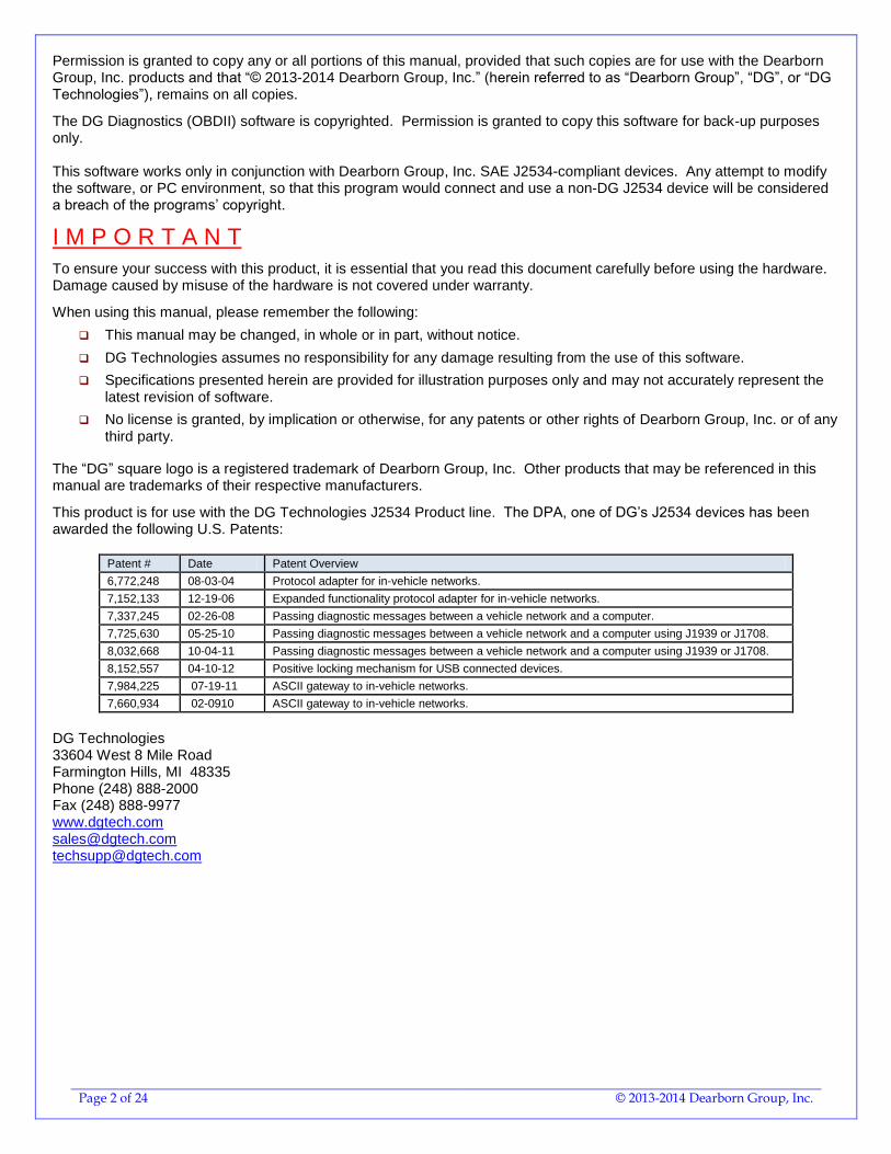
This product is for use with the DG Technologies J2534 Product line. The DPA, one of DG’s J2534 devices has been awarded the following U.S. Patents:
Patent # Date Patent Overview
6,772,248 08-03-04 Protocol adapter for in-vehicle networks.
7,152,133 12-19-06 Expanded functionality protocol adapter for in-vehicle networks.
7,337,245 02-26-08 Passing diagnostic messages between a vehicle network and a computer.
7,725,630 05-25-10 Passing diagnostic messages between a vehicle network and a computer using J1939 or J1708.
8,032,668 10-04-11 Passing diagnostic messages between a vehicle network and a computer using J1939 or J1708.
8,152,557 04-10-12 Positive locking mechanism for USB connected devices.
7,984,225 07-19-11 ASCII gateway to in-vehicle networks.
7,660,934 02-0910 ASCII gateway to in-vehicle networks.
DG Technologies 33604 West 8 Mile Road Farmington Hills, MI 48335 Phone (248) 888-2000 Fax (248) 888-9977 www.dgtech.com [email protected] [email protected]
Page 3 of 24 © 2013-2014 Dearborn Group, Inc.
Table of Contents
Table of Contents .......................................................................................................................................... 3 1. Safety First ........................................................................................................................................... 4 2. DG Diagnostics (OBDII) and DG Diagnostics (MD/HD) Overview .................................................... 5
2.1. User Manual ................................................................................................................................. 5 2.2. 2013 and Newer Volvo Vehicles with OBDII Connector – DGD (MD/HD) .................................... 6 2.3. DG Diagnostics “Startup” Program ............................................................................................... 6
3. DG Diagnostics (OBDII) Program Overview ...................................................................................... 7 4. DG Devices and their Supported Protocols ...................................................................................... 8
4.1. Introduction to OBDII Vehicle Protocols ....................................................................................... 8 4.2. DPA 5 Dual-CAN / Bluetooth ........................................................................................................ 8 4.3. DG d-briDGe ................................................................................................................................ 8 4.4. Netbridge Quad-CAN Interface .................................................................................................... 8 4.5. VSI-2534 ...................................................................................................................................... 8 4.6. Softbridge ..................................................................................................................................... 8
5. Features and OBDII Modes ................................................................................................................. 9 6. DG Diagnostics (OBDII) Program Help – Home Screen .................................................................. 10
6.1. Connect / Disconnect Button ...................................................................................................... 10 6.2. Raw Message Output and Status Message Output Fields ......................................................... 10 6.3. User Manual Button .................................................................................................................... 10 6.4. Vehicle Report Button ................................................................................................................ 10 6.5. Exit Application Button ............................................................................................................... 10 6.6. File Menu.................................................................................................................................... 10
7. Configuration Parameters Dialog ..................................................................................................... 11 7.1. Device and General Program Settings ....................................................................................... 11 7.2. Read Timeout (ms) ..................................................................................................................... 11 7.3. Numeric Display ......................................................................................................................... 11 7.4. Data Logging Settings ................................................................................................................ 11 7.5. Protocol Specific Tester ID Settings ........................................................................................... 12 7.6. Buttons ....................................................................................................................................... 12
8. DG Diagnostics (OBDII) – DTCs Screen ........................................................................................... 13 8.1. DTC Grids .................................................................................................................................. 13 8.2. Read DTCs Button ..................................................................................................................... 13 8.3. Clear DTCs Button ..................................................................................................................... 13
9. DG Diagnostics (OBDII) Program Help – DTC Freeze Frame Screen ............................................ 14 9.1. ECM To Monitor ......................................................................................................................... 14 9.2. Display Window .......................................................................................................................... 14 9.3. Request Freeze Frame Data Button ........................................................................................... 14 9.4. DTC Causing Freeze Frame ...................................................................................................... 14
10. DG Diagnostics (OBDII) Program Help – Parameters Screen ........................................................ 15 10.1. ECM To Monitor Combination Box ............................................................................................. 15 10.2. Display Window .......................................................................................................................... 15 10.3. Start Monitoring / Stop Monitoring Button ................................................................................... 15
11. DG Diagnostics (OBDII) Program Help – ECM Info Screen ............................................................ 16 11.1. ECM To Monitor Combination Box ............................................................................................. 16 11.2. Display Grid ................................................................................................................................ 16 11.3. Request ECM Information Button ............................................................................................... 16
12. DG Diagnostics (OBDII) Program Help – Monitors Screen ............................................................ 17 12.1. ECM to Monitor Combination Box .............................................................................................. 17 12.2. Display Grids and Text Boxes .................................................................................................... 17 12.3. Get Monitor/Certification Data Button ......................................................................................... 17
13. DG Diagnostics (OBDII) Program Help – Monitor Results Screen ................................................. 18 13.1. Screen for J1850, ISO 9141, ISO 14230 .................................................................................... 18 13.2. Screen for ISO 15765 ................................................................................................................. 19
14. DG Diagnostics (OBDII) Program Help – Console Screen ............................................................. 20 14.1. Header Bytes .............................................................................................................................. 20 14.2. Message Data Bytes .................................................................................................................. 20 14.3. Message Length ......................................................................................................................... 20
15. DG Diagnostics (OBDII) Program Help – Register Screen ............................................................. 21 16. DG Diagnostics (OBDII) Program Help – Vehicle Report ............................................................... 22 17. The “File” Menu and Associated Entries ......................................................................................... 23
17.1. Configuration .............................................................................................................................. 23 17.2. Display ECMs and Supported Parameters ................................................................................. 23
18. DG Diagnostics (OBDII) Program Help – “As Is”, No Warranty ..................................................... 24
Page 4 of 24 © 2013-2014 Dearborn Group, Inc.
1. Safety First
It is essential that the user read this document carefully before using the hardware. DG Diagnostics (DGD) is to be used by those trained in the troubleshooting and diagnostics of light-duty through heavy-duty vehicles and equipment. The user is assumed to have a very good understanding of the electronic systems contained on these and the potential hazards related to working in a shop-floor environment. DG Technologies understands that there are numerous safety hazards that cannot be foreseen, so we recommend that the user read and follow all safety messages in this manual, on all of your shop equipment, from your vehicle manuals, as well as internal shop documents and operating procedures.
Always block all wheels when testing.
Use extreme caution when working around electricity. When diagnosing any vehicle, there is the risk of electric shock both from battery-level voltage, vehicle voltages, and from building voltage.
Do not smoke or allow sparks or open flames near any part of the vehicle fueling system or vehicle batteries.
Always work in an adequately ventilated area, and route vehicle exhaust outdoors.
Do not use this product in an environment where fuel, fuel vapor, exhaust fumes, or other potentially hazardous liquids, solids, or gas/vapors could collect and/or possibly ignite, such as in an unventilated area or other confined space, including below-ground areas.
Page 5 of 24 © 2013-2014 Dearborn Group, Inc.
2. DG Diagnostics (OBDII) and DG Diagnostics (MD/HD) Overview
New to DG RP1210/J2534 device releases is a new member to the DG Diagnostics (DGD) application family. It is called “DG Diagnostics (OBDII)” and works with light and medium-duty vehicles! Now, by purchasing a DG diagnostic adapter you have the capability to work on any light-duty through heavy-duty vehicle.
NOTE: The DPA 5 Dual-CAN, DPA 5 Quad-CAN, Netbridge, d-Bridge, and Softbridge devices do not support the J1850 PWM protocol that was common on Ford vehicles prior to about 2005 (non-CAN-based). If you have an older Ford you wish to work on, DG recommends using our VSI-2534 device.
The DG Diagnostics application previously called “DG Diagnostics or DGD” that was written for the medium and heavy-duty vehicles using a Deutsch 6-pin or Deutsch 9-pin connector has been renamed “DG Diagnostics (MD/HD)”.
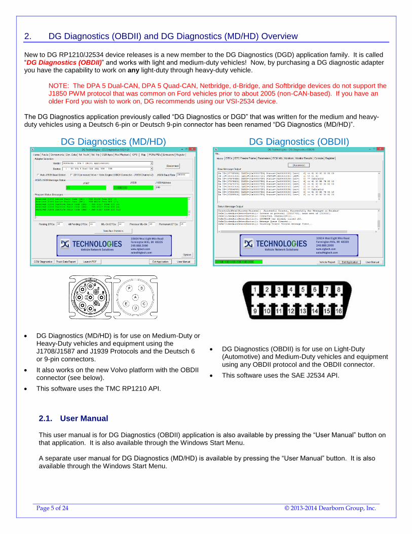
DG Diagnostics (MD/HD) DG Diagnostics (OBDII)
DG Diagnostics (MD/HD) is for use on Medium-Duty or Heavy-Duty vehicles and equipment using the J1708/J1587 and J1939 Protocols and the Deutsch 6 or 9-pin connectors.
It also works on the new Volvo platform with the OBDII connector (see below).
This software uses the TMC RP1210 API.
DG Diagnostics (OBDII) is for use on Light-Duty (Automotive) and Medium-Duty vehicles and equipment using any OBDII protocol and the OBDII connector.
This software uses the SAE J2534 API.
2.1. User Manual
This user manual is for DG Diagnostics (OBDII) application is also available by pressing the “User Manual” button on that application. It is also available through the Windows Start Menu. A separate user manual for DG Diagnostics (MD/HD) is available by pressing the “User Manual” button. It is also available through the Windows Start Menu.
Page 6 of 24 © 2013-2014 Dearborn Group, Inc.
2.2. 2013 and Newer Volvo Vehicles with OBDII Connector – DGD (MD/HD)
DG Diagnostics (MD/HD) and DG Diagnostics (OBDII) can BOTH be used on the 2013 and newer Volvo vehicles that have the OBDII diagnostics connector provided you have the correct cabling (see your diagnostic adapter user manual). If you want to connect to the J1708/J1587 and J1939 protocols using DGD (MD/HD), just check the following checkbox. The DGD connection to this Volvo platform is covered in the DGD (MD/HD) user manual.
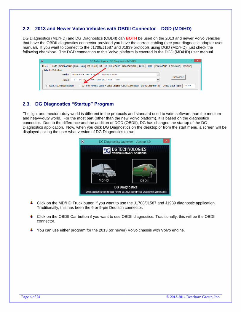
2.3. DG Diagnostics “Startup” Program
The light and medium-duty world is different in the protocols and standard used to write software than the medium and heavy-duty world. For the most part (other than the new Volvo platform), it is based on the diagnostics connector. Due to the difference and the addition of DGD (OBDII), DG has changed the startup of the DG Diagnostics application. Now, when you click DG Diagnostics on the desktop or from the start menu, a screen will be displayed asking the user what version of DG Diagnostics to run.
Click on the MD/HD Truck button if you want to use the J1708/J1587 and J1939 diagnostic application. Traditionally, this has been the 6 or 9-pin Deutsch connector.
Click on the OBDII Car button if you want to use OBDII diagnostics. Traditionally, this will be the OBDII
connector.
You can use either program for the 2013 (or newer) Volvo chassis with Volvo engine.
Page 7 of 24 © 2013-2014 Dearborn Group, Inc.
3. DG Diagnostics (OBDII) Program Overview
DG Diagnostics (OBDII) is a highly useful, general purpose OBDII (SAE J1979) diagnostics program provided “free-of-charge” to DG’s J2534 product customers. Some of the high-level features are:
Implementation of all J1979 OBDII-Defined Diagnostic “Modes”.
Implementation of all J1979 OBDII-Defined Diagnostic “Parameters”.
Implementation of all SAE J2012-Defined Diagnostic Trouble Codes at the Time of this Writing.
The program can:
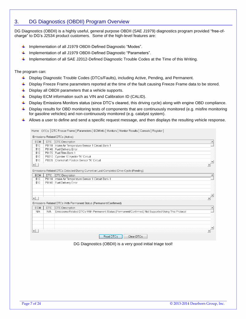
Display Diagnostic Trouble Codes (DTCs/Faults), including Active, Pending, and Permanent.
Display Freeze Frame parameters reported at the time of the fault causing Freeze Frame data to be stored.
Display all OBDII parameters that a vehicle supports.
Display ECM information such as VIN and Calibration ID (CALID).
Display Emissions Monitors status (since DTC’s cleared, this driving cycle) along with engine OBD compliance.
Display results for OBD monitoring tests of components that are continuously monitored (e.g. misfire monitoring for gasoline vehicles) and non-continuously monitored (e.g. catalyst system).
Allows a user to define and send a specific request message, and then displays the resulting vehicle response.
DG Diagnostics (OBDII) is a very good initial triage tool!
Page 8 of 24 © 2013-2014 Dearborn Group, Inc.
4. DG Devices and their Supported Protocols
4.1. Introduction to OBDII Vehicle Protocols
ISO 15765 (CAN-based)
o This protocol was mandated in all automobiles starting in 2008.
o There are two options, 11-bit identifiers and 29-bit identifiers. DGD (OBDII) supports both modes.
J1850 VPW (Variable Pulse Width)
o This protocol is very common on General Motors (GM) vehicles prior to 2008.
J1850 PWM (Pulse Width Modulation)
o This protocol is very common on Ford vehicles prior to 2008.
o See the sections below about which DG products support/do not support this protocol.
ISO 9141 and ISO 14230
o These protocols are typically found on pre-2008 European vehicles.
The DG Diagnostics (OBDII) application program can be used with the following DG products and vehicle protocols:
4.2. DPA 5 Dual-CAN / Bluetooth
ISO 15765 (CAN-based)
J1850 VPW (Variable Pulse Width)
ISO 9141 and ISO 14230
The DPA 5 does not support the Ford J1850PWM protocol. You will not be able to use the DPA 5 on Ford vehicles from about MY2004 and prior. All Ford vehicles with the CAN/ISO15765 protocol are supported.
4.3. DG d-briDGe
ISO 15765 (CAN-based)
J1850 VPW (Variable Pulse Width)
ISO 9141 and ISO 14230
4.4. Netbridge Quad-CAN Interface
ISO 15765 (CAN-based)
4.5. VSI-2534
ISO 15765 (CAN-based)
J1850 VPW (Variable Pulse Width)
ISO 9141 and ISO 14230
4.6. Softbridge
ISO 15765 (CAN-based)
J1850 VPW (Variable Pulse Width)
ISO 9141 and ISO 14230
NOTE: Numbers with the prefix “$” or “0x” are numbers in the hexadecimal number system (base 16). ECMs will always be represented in hexadecimal notation, however there is an option to display other numbers used in the program in decimal or hexadecimal.
Page 9 of 24 © 2013-2014 Dearborn Group, Inc.
5. Features and OBDII Modes
Read and Display Diagnostic Trouble Codes (DTCs) in “Numeric” And “Text” (SAE J2012) Form.
o Active Emissions-Related DTCs - Mode 3.
o Pending Emissions-Related DTCs Detected During Last Or Current Drive Cycle - Mode 7.
o Pending Emissions-Related DTCs With A Permanent Status – Mode 10
o Request ECMs to Clear DTCs and Monitors - Mode 4.
Display “Freeze Frame” Data – Mode 2
o Display All Parameters Recorded At The Time Of The Fault That Caused Freeze Frame To Be Stored.
Display All Parameters That The Vehicle Supports In Both English And Metric Values - Mode 1.
Display ECM Information Such As VIN and Calibration ID (CALID) – Mode 9.
Display The Value Of Monitors That Have Run And The Status Of The Malfunction Indicator Light (MIL).
o Monitor Status Since DTCs Cleared - Mode 1 PID 1.
o Monitor Status This Driving Cycle - Mode 1 PID 65.
o OBD Requirements Vehicle Certified To - Mode 1 PID 28.
o OBD Requirements Vehicle Certified To - Mode 1 PID 95.
Send Any Generic OBDII Command Using The Console Screen – All Modes.
o This Covers Sending And Receiving Raw Message Data.
Create A Vehicle Report In HTML Based On All Information That Has Been Discovered.
DGD (OBDII) supports all OBDII “Modes” from 1..10 ($01..$0A) with the exception of Mode 5 (O2 Sensor Test Results). Most vehicle OEMs have implemented Mode 5 results in Mode 6 which is supported in the “Monitor Results” tab. NOTE: Mode 5 has been implemented and tested with “fake” data. However we have not found a vehicle or OBDII simulator supporting this Mode, therefore the “O2 Sensor” tab is not visible. If you have a vehicle known to support Mode 5, please contact DG so that we can enable that tab and provide you with a beta copy of the DGD (OBDII) software.
Page 10 of 24 © 2013-2014 Dearborn Group, Inc.
6. DG Diagnostics (OBDII) Program Help – Home Screen
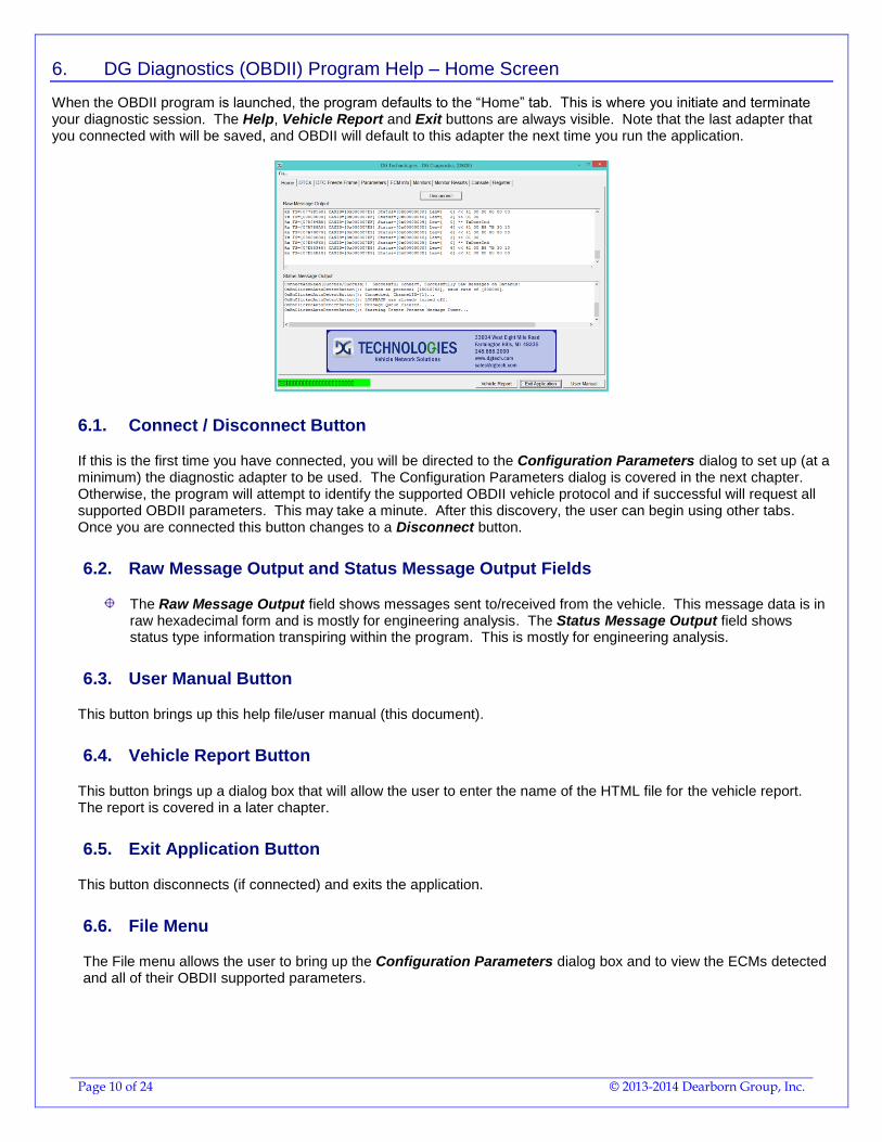
When the OBDII program is launched, the program defaults to the “Home” tab. This is where you initiate and terminate your diagnostic session. The Help, Vehicle Report and Exit buttons are always visible. Note that the last adapter that you connected with will be saved, and OBDII will default to this adapter the next time you run the application.
6.1. Connect / Disconnect Button
If this is the first time you have connected, you will be directed to the Configuration Parameters dialog to set up (at a minimum) the diagnostic adapter to be used. The Configuration Parameters dialog is covered in the next chapter. Otherwise, the program will attempt to identify the supported OBDII vehicle protocol and if successful will request all supported OBDII parameters. This may take a minute. After this discovery, the user can begin using other tabs. Once you are connected this button changes to a Disconnect button.
6.2. Raw Message Output and Status Message Output Fields
The Raw Message Output field shows messages sent to/received from the vehicle. This message data is in raw hexadecimal form and is mostly for engineering analysis. The Status Message Output field shows status type information transpiring within the program. This is mostly for engineering analysis.
6.3. User Manual Button
This button brings up this help file/user manual (this document).
6.4. Vehicle Report Button
This button brings up a dialog box that will allow the user to enter the name of the HTML file for the vehicle report. The report is covered in a later chapter.
6.5. Exit Application Button
This button disconnects (if connected) and exits the application.
6.6. File Menu
The File menu allows the user to bring up the Configuration Parameters dialog box and to view the ECMs detected and all of their OBDII supported parameters.
Page 11 of 24 © 2013-2014 Dearborn Group, Inc.
7. Configuration Parameters Dialog
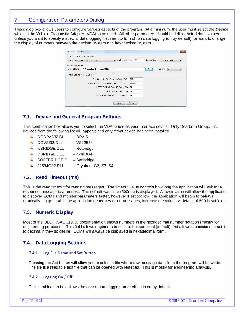
This dialog box allows users to configure various aspects of the program. At a minimum, the user must select the Device, which is the Vehicle Diagnostic Adapter (VDA) to be used. All other parameters should be left to their default values unless you want to specify a specific data logging file, want to turn off/on data logging (on by default), or want to change the display of numbers between the decimal system and hexadecimal system.
7.1. Device and General Program Settings
This combination box allows you to select the VDA to use as your interface device. Only Dearborn Group, Inc. devices from the following list will appear; and only if that device has been installed.
DGDPA532.DLL – DPA 5
DGVSI32.DLL – VSI 2534
NBRIDGE.DLL – Netbridge
DBRIDGE.DLL – d-briDGe
SOFTBRIDGE.DLL – Softbridge
J2534G32.DLL – Gryphon, G2, S3, S4
7.2. Read Timeout (ms)
This is the read timeout for reading messages. The timeout value controls how long the application will wait for a response message to a request. The default wait time (500ms) is displayed. A lower value will allow the application to discover ECMs and monitor parameters faster, however if set too low, the application will begin to behave erratically. In general, if the application generates error messages, increase the value. A default of 500 is sufficient.
7.3. Numeric Display
Most of the OBDII (SAE J1979) documentation shows numbers in the hexadecimal number notation (mostly for engineering purposes). This field allows engineers to set it to hexadecimal (default) and allows technicians to set it to decimal if they so desire. ECMs will always be displayed in hexadecimal form.
7.4. Data Logging Settings
7.4.1. Log File Name and Set Button
Pressing the Set button will allow you to select a file where raw message data from the program will be written. The file is a readable text file that can be opened with Notepad. This is mostly for engineering analysis.
7.4.2. Logging On / Off
This combination box allows the user to turn logging on or off. It is on by default.
Page 12 of 24 © 2013-2014 Dearborn Group, Inc.
7.5. Protocol Specific Tester ID Settings
The user should refrain from changing these values as they may affect the program adversely. These values are for engineering purposes only.
7.5.1. ISO15765 11-bit CAN Tester ID (Default 7DF)
This edit box allows setting the Tester ID to a value other than the default.
7.5.2. ISO15765 29-bit CAN Tester ID (Default 18DB33F1)
This edit box allows setting the Tester ID to a value other than the default.
7.5.3. J1850 VPW/PWM Tester ID (Default F1)
This edit box allows setting the Tester Source Address to a value other than the default.
7.5.4. ISO9141 Tester ID (Default F1)
This edit box allows setting the Tester Source Address to a value other than the default.
7.5.5. ISO14230 (KWP2000) Tester ID (Default F1)
This edit box allows setting the Tester Source Address to a value other than the default.
7.6. Buttons
7.6.1. Save
Pressing this button saves current settings. The user can now connect to the device selected.
7.6.2. Cancel
Exit dialog box and do not save current settings. The user must select a device and press the Save button before a connection can be made.
Page 13 of 24 © 2013-2014 Dearborn Group, Inc.
8. DG Diagnostics (OBDII) – DTCs Screen
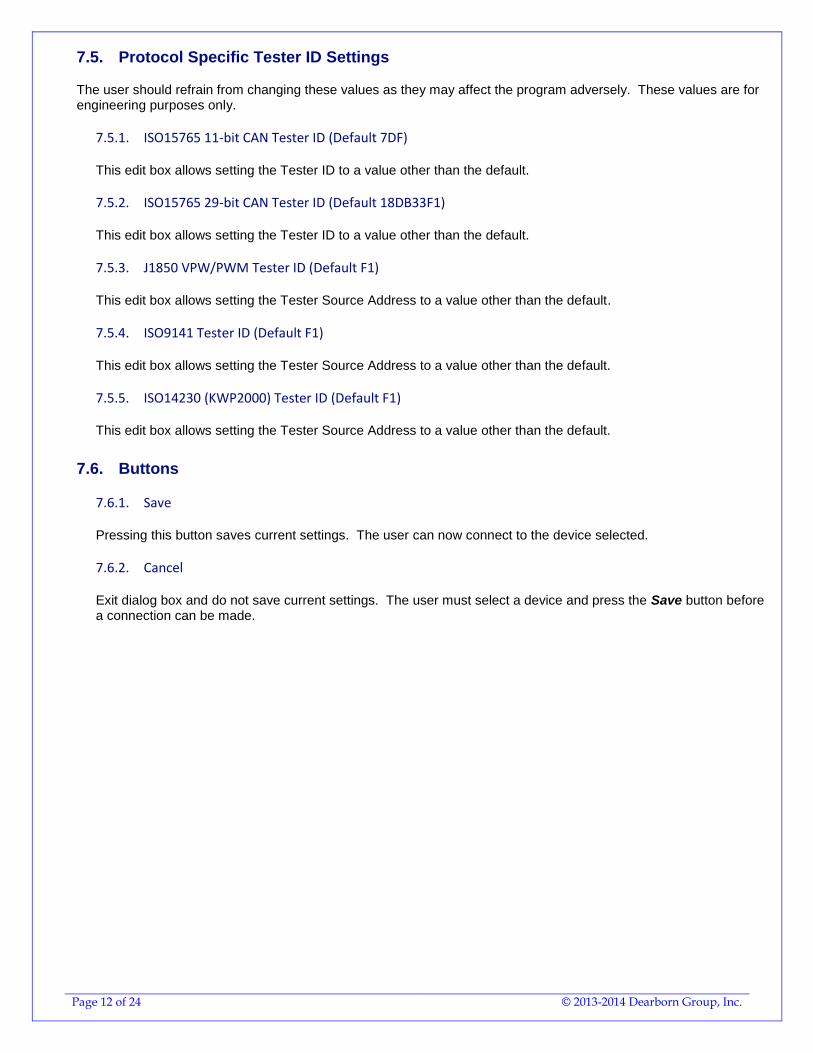
8.1. DTC Grids
There are three types of OBDII fault codes, all of them are “Emissions Related”. There are “Active DTCs”, “Pending DTCs”, and “Permanent/Confirmed DTCs”. There are 4 types of faults defined in the SAE J2012 specification, they are:
P - Powertrain C - Chassis B - Body Control U - Network
NOTE: Permanent DTCs are not supported by the J1850, ISO 9141, or the ISO 14230 protocols (older protocols).
8.2. Read DTCs Button
Pressing this button will request DTCs from all ECMs and display them.
8.3. Clear DTCs Button
Pressing this button will “request” that all DTCs and Monitor information be cleared from all OBD controllers. Clearing faults is a “request” some ECMs may not honor. If DTCs or Monitors are not cleared, this is not a defect in the program!
Page 14 of 24 © 2013-2014 Dearborn Group, Inc.
9. DG Diagnostics (OBDII) Program Help – DTC Freeze Frame Screen
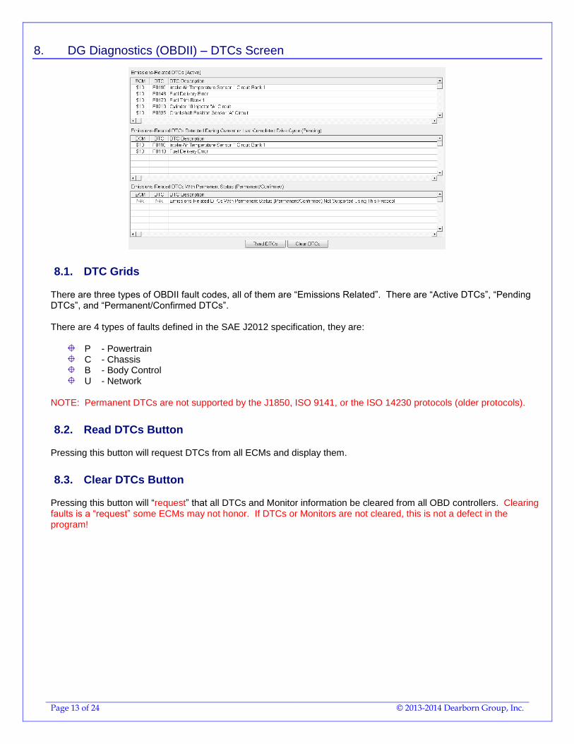
Some ECMs store Freeze Frame data when a fault code occurs. This data usually gives a technician some insight into what was going on within the vehicle at the time a DTC was stored.
9.1. ECM To Monitor
Different ECMs can store Freeze Frame data, so select the ECM to request Freeze Frame data from. By default the primary OBD device will be selected.
9.2. Display Window
Depending on what Freeze Frame PIDs are supported by the selected ECM, the information will be displayed in a tree format. Simple parameters will be displayed on the same line and do not have the plus sign [+]. The first column will be the value in metric units and the second value will be in English units. Complex (binary-type) parameters have the plus sign [+] next to them. Press the plus sign to view all sub-parameters of the complex parameter. The first column will be the value in metric units and the second value will be in English units.
9.3. Request Freeze Frame Data Button
Pressing this button will request Freeze Frame DTCs and the DTC Causing Freeze Frame from the ECM selected and display the information returned. A message box will appear stating the requests have been completed.
9.4. DTC Causing Freeze Frame
This is the DTC that caused the ECM to store the Freeze Frame data.
Page 15 of 24 © 2013-2014 Dearborn Group, Inc.
10. DG Diagnostics (OBDII) Program Help – Parameters Screen
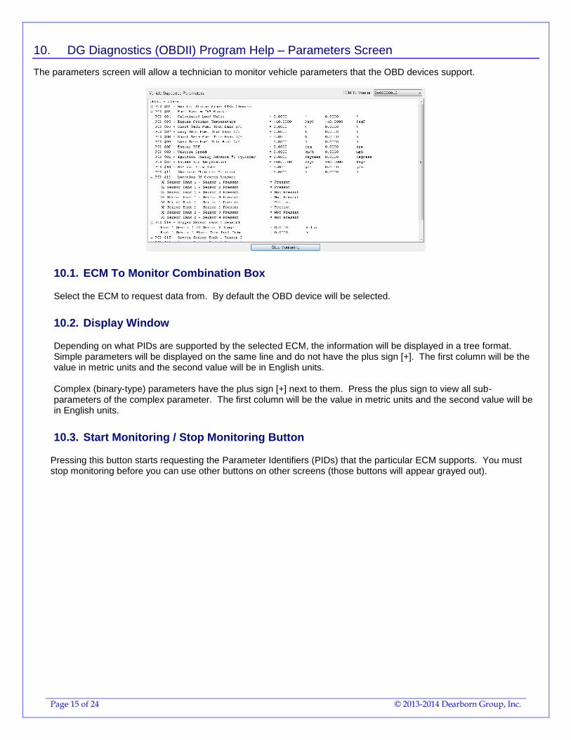
The parameters screen will allow a technician to monitor vehicle parameters that the OBD devices support.
10.1. ECM To Monitor Combination Box
Select the ECM to request data from. By default the OBD device will be selected.
10.2. Display Window
Depending on what PIDs are supported by the selected ECM, the information will be displayed in a tree format. Simple parameters will be displayed on the same line and do not have the plus sign [+]. The first column will be the value in metric units and the second value will be in English units. Complex (binary-type) parameters have the plus sign [+] next to them. Press the plus sign to view all sub-parameters of the complex parameter. The first column will be the value in metric units and the second value will be in English units.
10.3. Start Monitoring / Stop Monitoring Button
Pressing this button starts requesting the Parameter Identifiers (PIDs) that the particular ECM supports. You must stop monitoring before you can use other buttons on other screens (those buttons will appear grayed out).
Page 16 of 24 © 2013-2014 Dearborn Group, Inc.
11. DG Diagnostics (OBDII) Program Help – ECM Info Screen
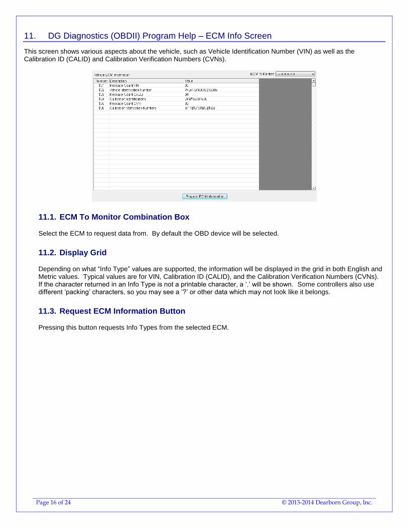
This screen shows various aspects about the vehicle, such as Vehicle Identification Number (VIN) as well as the Calibration ID (CALID) and Calibration Verification Numbers (CVNs).
11.1. ECM To Monitor Combination Box
Select the ECM to request data from. By default the OBD device will be selected.
11.2. Display Grid
Depending on what “Info Type” values are supported, the information will be displayed in the grid in both English and Metric values. Typical values are for VIN, Calibration ID (CALID), and the Calibration Verification Numbers (CVNs). If the character returned in an Info Type is not a printable character, a ‘.’ will be shown. Some controllers also use different ‘packing’ characters, so you may see a ‘?’ or other data which may not look like it belongs.
11.3. Request ECM Information Button
Pressing this button requests Info Types from the selected ECM.
Page 17 of 24 © 2013-2014 Dearborn Group, Inc.
12. DG Diagnostics (OBDII) Program Help – Monitors Screen
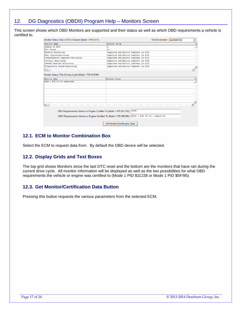
This screen shows which OBD Monitors are supported and their status as well as which OBD requirements a vehicle is certified to.
12.1. ECM to Monitor Combination Box
Select the ECM to request data from. By default the OBD device will be selected.
12.2. Display Grids and Text Boxes
The top grid shows Monitors since the last DTC reset and the bottom are the monitors that have ran during the current drive cycle. All monitor information will be displayed as well as the two possibilities for what OBD requirements the vehicle or engine was certified to (Mode 1 PID $1C/28 or Mode 1 PID $5F/95).
12.3. Get Monitor/Certification Data Button
Pressing this button requests the various parameters from the selected ECM.
Page 18 of 24 © 2013-2014 Dearborn Group, Inc.
13. DG Diagnostics (OBDII) Program Help – Monitor Results Screen
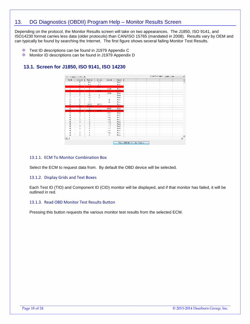
Depending on the protocol, the Monitor Results screen will take on two appearances. The J1850, ISO 9141, and ISO14230 format carries less data (older protocols) than CAN/ISO 15765 (mandated in 2008). Results vary by OEM and can typically be found by searching the Internet. The first figure shows several failing Monitor Test Results.
Test ID descriptions can be found in J1979 Appendix C Monitor ID descriptions can be found in J1979 Appendix D
13.1. Screen for J1850, ISO 9141, ISO 14230
13.1.1. ECM To Monitor Combination Box
Select the ECM to request data from. By default the OBD device will be selected.
13.1.2. Display Grids and Text Boxes
Each Test ID (TID) and Component ID (CID) monitor will be displayed, and if that monitor has failed, it will be outlined in red.
13.1.3. Read OBD Monitor Test Results Button
Pressing this button requests the various monitor test results from the selected ECM.
Page 19 of 24 © 2013-2014 Dearborn Group, Inc.
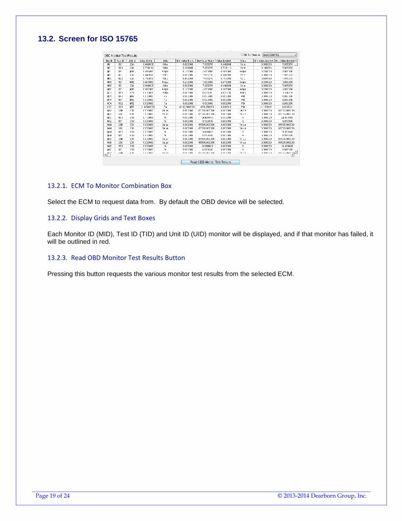
13.2. Screen for ISO 15765
13.2.1. ECM To Monitor Combination Box
Select the ECM to request data from. By default the OBD device will be selected.
13.2.2. Display Grids and Text Boxes
Each Monitor ID (MID), Test ID (TID) and Unit ID (UID) monitor will be displayed, and if that monitor has failed, it will be outlined in red.
13.2.3. Read OBD Monitor Test Results Button
Pressing this button requests the various monitor test results from the selected ECM.
Page 20 of 24 © 2013-2014 Dearborn Group, Inc.
14. DG Diagnostics (OBDII) Program Help – Console Screen
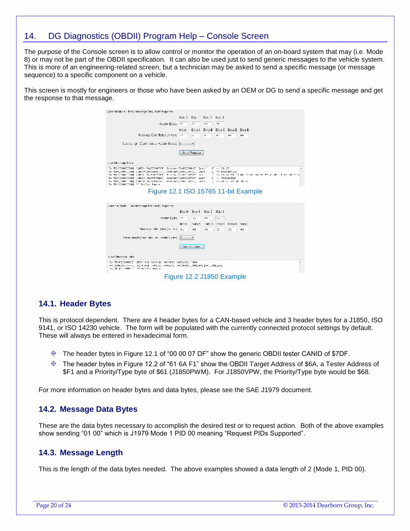
The purpose of the Console screen is to allow control or monitor the operation of an on-board system that may (i.e. Mode 8) or may not be part of the OBDII specification. It can also be used just to send generic messages to the vehicle system. This is more of an engineering-related screen, but a technician may be asked to send a specific message (or message sequence) to a specific component on a vehicle. This screen is mostly for engineers or those who have been asked by an OEM or DG to send a specific message and get the response to that message.
Figure 12.1 ISO 15765 11-bit Example
Figure 12.2 J1850 Example
14.1. Header Bytes
This is protocol dependent. There are 4 header bytes for a CAN-based vehicle and 3 header bytes for a J1850, ISO 9141, or ISO 14230 vehicle. The form will be populated with the currently connected protocol settings by default. These will always be entered in hexadecimal form.
The header bytes in Figure 12.1 of “00 00 07 DF” show the generic OBDII tester CANID of $7DF.
The header bytes in Figure 12.2 of “61 6A F1” show the OBDII Target Address of $6A, a Tester Address of $F1 and a Priority/Type byte of $61 (J1850PWM). For J1850VPW, the Priority/Type byte would be $68.
For more information on header bytes and data bytes, please see the SAE J1979 document.
14.2. Message Data Bytes
These are the data bytes necessary to accomplish the desired test or to request action. Both of the above examples show sending “01 00” which is J1979 Mode 1 PID 00 meaning “Request PIDs Supported”.
14.3. Message Length
This is the length of the data bytes needed. The above examples showed a data length of 2 (Mode 1, PID 00).
Page 21 of 24 © 2013-2014 Dearborn Group, Inc.
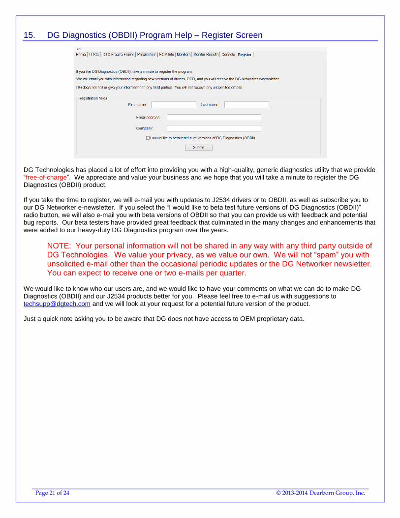
15. DG Diagnostics (OBDII) Program Help – Register Screen
DG Technologies has placed a lot of effort into providing you with a high-quality, generic diagnostics utility that we provide “free-of-charge”. We appreciate and value your business and we hope that you will take a minute to register the DG Diagnostics (OBDII) product. If you take the time to register, we will e-mail you with updates to J2534 drivers or to OBDII, as well as subscribe you to our DG Networker e-newsletter. If you select the “I would like to beta test future versions of DG Diagnostics (OBDII)” radio button, we will also e-mail you with beta versions of OBDII so that you can provide us with feedback and potential bug reports. Our beta testers have provided great feedback that culminated in the many changes and enhancements that were added to our heavy-duty DG Diagnostics program over the years.
NOTE: Your personal information will not be shared in any way with any third party outside of DG Technologies. We value your privacy, as we value our own. We will not “spam” you with unsolicited e-mail other than the occasional periodic updates or the DG Networker newsletter. You can expect to receive one or two e-mails per quarter.
We would like to know who our users are, and we would like to have your comments on what we can do to make DG Diagnostics (OBDII) and our J2534 products better for you. Please feel free to e-mail us with suggestions to [email protected] and we will look at your request for a potential future version of the product. Just a quick note asking you to be aware that DG does not have access to OEM proprietary data.
Page 22 of 24 © 2013-2014 Dearborn Group, Inc.
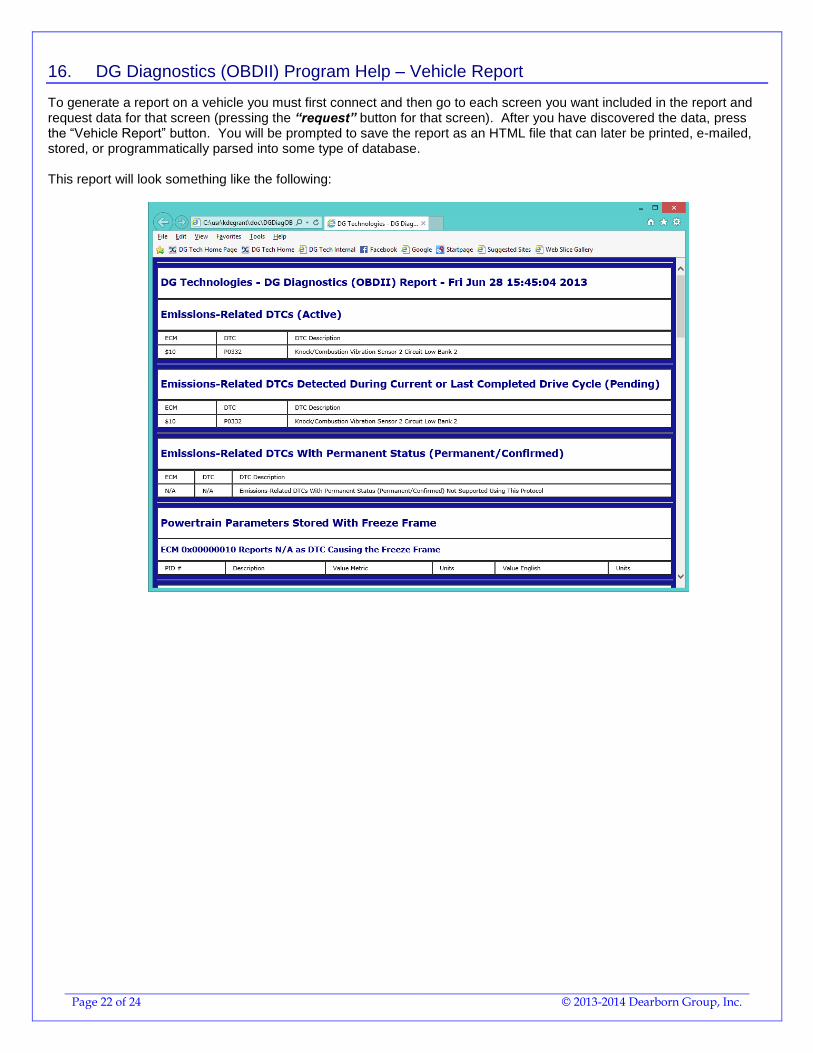
16. DG Diagnostics (OBDII) Program Help – Vehicle Report
To generate a report on a vehicle you must first connect and then go to each screen you want included in the report and request data for that screen (pressing the “request” button for that screen). After you have discovered the data, press the “Vehicle Report” button. You will be prompted to save the report as an HTML file that can later be printed, e-mailed, stored, or programmatically parsed into some type of database. This report will look something like the following:
Page 23 of 24 © 2013-2014 Dearborn Group, Inc.
17. The “File” Menu and Associated Entries
The file menu has several options. The first option is program configuration (see previous chapter) and the second is to display which ECMs are speaking with DGD (OBDII) and what modes/parameters each ECM supports.
17.1. Configuration
This has been covered in a previous chapter.
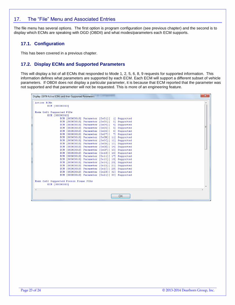
17.2. Display ECMs and Supported Parameters
This will display a list of all ECMs that responded to Mode 1, 2, 5, 6, 8, 9 requests for supported information. This information defines what parameters are supported by each ECM. Each ECM will support a different subset of vehicle parameters. If OBDII does not display a particular parameter, it is because that ECM reported that the parameter was not supported and that parameter will not be requested. This is more of an engineering feature.
Page 24 of 24 © 2013-2014 Dearborn Group, Inc.
18. DG Diagnostics (OBDII) Program Help – “As Is”, No Warranty
This program is provided “AS IS” and is “free-of-charge” for DG’s J2534 product owners. It was intended to be a value-added feature to enhance the value of DG’s J2534 product line. DG Technologies disclaims all warranties, either expresses or implied, including any implied warranty of merchantability or fitness for any particular purpose. DG Technologies shall have no liability to anyone for incidental or consequential damages for merchandise which is provided "AS IS". DG Technologies makes no warranty as to the performance of this product. DG Technologies has placed this program through extensive testing, however as with any software, there could be deficiencies. Therefore we cannot guarantee that any parameters displayed are accurate. We hope that you enjoy this tool and find it of value. If you find deficiencies, or have requests for the addition of non-OEM-proprietary functionality, please do not hesitate to contact us at:
DG Technologies 33604 West 8 Mile Road Farmington Hills, MI 48335 Phone (248) 888-2000 www.dgtech.com [email protected]