DFS60 Incremental Encoders - Allied Electronics · DFS60 – IncrEmEntal EncoDErS | SIcK...
44
High-resolution, programmable encoder for sophisticated applications DFS60 Incremental Encoders PRODUCT INFORMATION
Transcript of DFS60 Incremental Encoders - Allied Electronics · DFS60 – IncrEmEntal EncoDErS | SIcK...

High-resolution, programmable encoder for sophisticated applications
DFS60Incremental Encoders
Pr
oD
uc
t In
Fo
rm
atI
on

Incremental encoders
2
DFS60
D F S 6 0 – I n c r E m E n ta l E n c o D E r S | S I c K 8012072/2013-04-26Subject to change without notice
Product descriptionThe DFS60 is a high-resolution incremen-tal encoder with a diameter of 60 mm. It offers a wide variety of customer-specific mechanical and electric adjustments. Programming of the output signal, zero pulse and resolution of up to 65,356
pulses is a unique feature for the market. The high enclosure rating, wide temperature range and large ball bearing distance make the DFS60 the ideal en-coder for industrial applications in harsh environments.
at a glance • Compact installation depth • High resolution up to 16 bits • Optionally programmable: Output volt-
age, zero pulse position, zero pulse width and number of pulses
• Connection: Radial or axial cable outlet, M23 or M12 connector, axial or radial
• Electrical interfaces: 5 V & 24 V TTL/RS-422, 24 V HTL/push pull
• Mechanical interfaces: face mount or servo flange, blind or through hollow shaft
• Remote 0-SET possible
Your benefit • Reduced storage costs and downtime
due to customer-specific program-ming
• Variety of different mechanical and electrical interfaces enable the encoder to be optimally adjusted to fit the installation situation
• Excellent concentricity even at high speeds
• High resolution of up to 16 bits en-sures precise measurements
• Permanent and safe operation due to a high enclosure rating, temperature resistance and a long bearing lifetime
• Programmability via the PGT-08 pro-gramming software and the PGT-10-S display programming tool allow the encoder to be adapted flexibly and quickly according to customer needs
• Programmable zero pulse position simplifies installation
High-resolution, programmable encoder for sophisticated applications
additional informationDetailed technical data . . . . . . . . . . . .3
Maximum revolution range. . . . . . . . . .6
Ordering information. . . . . . . . . . . . . . .7
Dimensional drawings . . . . . . . . . . . 14
PIN and core assignment . . . . . . . . . 22
Interfaces. . . . . . . . . . . . . . . . . . . . . . 23
Accessories . . . . . . . . . . . . . . . . . . . . 25
UL certification not valid for all types. See order information
- www.mysick.com/en/DFS60For more information, just enter the link or scan the QR code and get direct access to technical data, CAD design models, operating instructions, software, application examples and much more.
Incremental encoders
3
DFS60
D F S 6 0 – I n c r E m E n ta l E n c o D E r S | S I c K8012072/2013-04-26Subject to change without notice
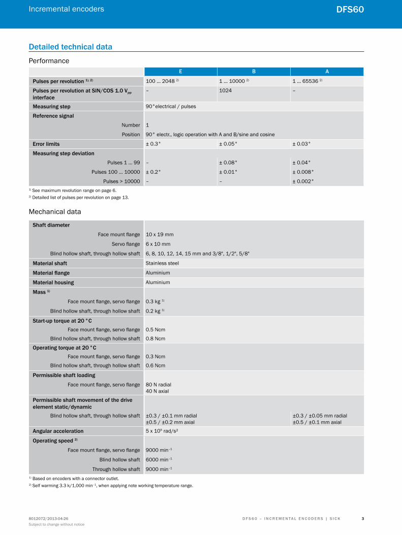
Detailed technical data
PerformanceE B a
Pulses per revolution 1), 2) 100 … 2048 2) 1 … 10000 2) 1 … 65536 2)
Pulses per revolution at SIn/coS 1.0 VPP interface
– 1024 –
measuring step 90°electrical / pulses
reference signal
Number 1
Position 90° electr., logic operation with A and B/sine and cosine
Error limits ± 0.3° ± 0.05° ± 0.03°
measuring step deviation
Pulses 1 … 99 – ± 0.08° ± 0.04°
Pulses 100 … 10000 ± 0.2° ± 0.01° ± 0.008°
Pulses > 10000 – – ± 0.002°1) See maximum revolution range on page 6.2) Detailed list of pulses per revolution on page 13.
Mechanical data
Shaft diameter
Face mount flange 10 x 19 mm
Servo flange 6 x 10 mm
Blind hollow shaft, through hollow shaft 6, 8, 10, 12, 14, 15 mm and 3/8", 1/2", 5/8"
material shaft Stainless steel
Material flange Aluminium
material housing Aluminium
mass 1)
Face mount flange, servo flange 0.3 kg 1)
Blind hollow shaft, through hollow shaft 0.2 kg 1)
Start-up torque at 20 °cFace mount flange, servo flange 0.5 Ncm
Blind hollow shaft, through hollow shaft 0.8 Ncm
operating torque at 20 °cFace mount flange, servo flange 0.3 Ncm
Blind hollow shaft, through hollow shaft 0.6 Ncm
Permissible shaft loading
Face mount flange, servo flange 80 N radial 40 N axial
Permissible shaft movement of the drive element static/dynamic
Blind hollow shaft, through hollow shaft ±0.3 / ±0.1 mm radial ±0.5 / ±0.2 mm axial
±0.3 / ±0.05 mm radial ±0.5 / ±0.1 mm axial
angular acceleration 5 x 10⁵ rad/s²
operating speed 2)
Face mount flange, servo flange 9000 min–1
Blind hollow shaft 6000 min–1
Through hollow shaft 9000 min–1
1) Based on encoders with a connector outlet.2) Self warming 3.3 k/1,000 min–1, when applying note working temperature range.
Incremental encoders
4
DFS60
D F S 6 0 – I n c r E m E n ta l E n c o D E r S | S I c K 8012072/2013-04-26Subject to change without notice
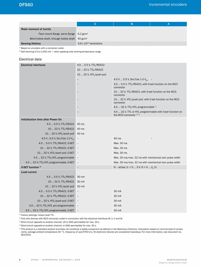
E B a
rotor moment of inertia
Face mount flange, servo flange 6.2 gcm²
Blind hollow shaft, through hollow shaft 40 gcm²
Bearing lifetime 3,6 x 10¹⁰ revolutions1) Based on encoders with a connector outlet.2) Self warming 3.3 k/1,000 min–1, when applying note working temperature range.
Electrical dataElectrical interfaces 4.5 … 5.5 V, TTL/RS422
10 … 32 V, TTL/RS422
10 … 32 V, HTL/push pull
– 4.5 V … 5.5 V, Sin/Cos 1.0 VPP –
– 4.5 … 5.5 V, TTL/RS422, with 0-set function on the M23 connector
– 10 … 32 V, TTL/RS422, with 0-set function on the M23 connector
– 10 … 32 V, HTL/push pull, with 0-set function on the M23 connector
– 4.5 … 32 V, TTL/HTL programmable 1)
– 4.5 … 32 V, TTL or HTL programmable with 0-set function on the M23 connector 1), 2)
Initialization time after Power on4.5 … 5.5 V, TTL/RS422 40 ms
10 … 32 V, TTL/RS422 40 ms
10 … 32 V, HTL/push pull 40 ms
4.5 V…5.5 V, Sin/Cos 1.0 VPP – 40 ms –
4.5 … 5.5 V, TTL/RS422, 0-SET – Max. 30 ms
10 … 32 V, TTL/RS422, 0-SET – Max. 30 ms
10 … 32 V, HTL/push pull, 0-SET – Max. 30 ms
4.5 … 32 V, TTL/HTL programmable – Max. 30 ms/max. 32 ms with mechanical zero pulse width
4.5 … 32 V, TTL/HTL programmable, 0-SET – Max. 30 ms/max. 32 ms with mechanical zero pulse width
0-SEt function 2) – H – active; (L = 0 ... 3 V, H = 4 ... US V)
load current
4.5 … 5.5 V, TTL/RS422 30 mA
10 … 32 V, TTL/RS422 30 mA
10 … 32 V, HTL/push pull 30 mA
4.5 … 5.5 V, TTL/RS422, 0-SET – 30 mA
10 … 32 V, TTL/RS422, 0-SET – 30 mA
10 … 32 V, HTL/push pull, 0-SET – 30 mA
4.5 … 32 V, TTL/HTL pro programmable – 30 mA
4.5 … 32 V, TTL/HTL programmable, 0-SET – 30 mA1) Factory settings: Output level TTL.2) Only with devices with M23 connector outlet in connection with the electrical interfaces M, U, V and W.3) Short-circuit opposite to another channel, US or GND permissible for max. 30 s.4) Short-circuit opposite to another channel, or GND permissible for max. 30 s.5) This product is a standard product and does not constitute a safety component as defined in the Machinery Directive. Calculation based on nominal load of compo-
nents, average ambient temperature 40 °C, frequency of use 8760 h/a. All electronic failures are considered hazardous. For more information, see document no. 8015532.

Incremental encoders
5
DFS60
D F S 6 0 – I n c r E m E n ta l E n c o D E r S | S I c K8012072/2013-04-26Subject to change without notice
E B a
load resistance
4.5 V…5.5 V, Sin/Cos 1.0 VPP – Min. 120 Ω –
operating current with no load
4.5 … 5.5 V, TTL/RS422 40 mA
4.5 V…5.5 V, Sin/Cos 1.0 VPP – 40 mA –
Power consumption with no load
10 … 32 V, TTL/RS422 0.5 W
10 … 32 V, HTL/push pull 0.5 W
4.5 … 5.5 V, TTL/RS422, 0-SET – 0.7 W
10 … 32 V, TTL/RS422, 0-SET – 0.7 W
10 … 32 V, HTL/push pull, 0-SET – 0.7 W
4.5 … 32 V, TTL/HTL pro programmable – 0.7 W
4.5 … 32 V, TTL/HTL programmable, 0-SET – 0.7 W
reverse polarity protection
4.5 … 5.5 V, TTL/RS422 No
10 … 32 V, TTL/RS422 Yes
10 … 32 V, HTL/push pull Yes
4.5 V…5.5 V, Sin/Cos 1.0 VPP –
4.5 … 5.5 V, TTL/RS422, 0-SET – Yes
10 … 32 V, TTL/RS422, 0-SET – Yes
10 … 32 V, HTL/push pull, 0-SET – Yes
4.5 … 32 V, TTL/HTL programmable – Yes
4.5 … 32 V, TTL/HTL programmable, 0-SET – Yes
Short-circuit protection of the outputs4.5 … 5.5 V, TTL/RS422 Yes 3)
10 … 32 V, TTL/RS422 Yes 4)
10 … 32 V, HTL/push pull Yes 3)
4.5 V…5.5 V, Sin/Cos 1.0 VPP – Yes 3) –
4.5 … 5.5 V, TTL/RS422, 0-SET – Yes 3)
10 … 32 V, TTL/RS422, 0-SET – Yes 4)
10 … 32 V, HTL/push pull, 0-SET – Yes 3)
4.5 … 32 V, TTL/HTL programmable – Yes, HTL 3) and TTL 4)
4.5 … 32 V, TTL/HTL programmable, 0-SET – Yes, HTL 3) ans TTL 4)
mttFd: mean time to dangerous failure 5) 300 years (EN ISO 13849-1)1) Factory settings: Output level TTL.2) Only with devices with M23 connector outlet in connection with the electrical interfaces M, U, V and W.3) Short-circuit opposite to another channel, US or GND permissible for max. 30 s.4) Short-circuit opposite to another channel, or GND permissible for max. 30 s.5) This product is a standard product and does not constitute a safety component as defined in the Machinery Directive. Calculation based on nominal load of compo-
nents, average ambient temperature 40 °C, frequency of use 8760 h/a. All electronic failures are considered hazardous. For more information, see document no. 8015532.

Incremental encoders
6
DFS60
D F S 6 0 – I n c r E m E n ta l E n c o D E r S | S I c K 8012072/2013-04-26Subject to change without notice
Ambient dataE B a
Emc 1) As per EN 61000-6-2 and EN 61000-6-3
Enclosure rating as per IEc 60529
On the shaft IP 65
On the housing, connector outlet 2) IP 67 (through hollow shaft IP 65)
On the housing, cable outlet IP 67 (through hollow shaft IP 65)
Permissible relative air humidity 90 % condensation on the optical scanner not permissible
Working temperature range 0 … +85 °C –30 … +100 °C
Storage temperature range (without packaging)
–40 … +100 °C
resistance
To shocks as per EN 60068-2-27 50 g/6 ms 70 g/6 ms 60 g/6 ms
To vibration as per EN 60068-2-6 20 g/ 10 … 2,000 Hz 30 g/ 10 … 2,000 Hz 20 g/ 10 … 2,000 Hz1) For the interfaces 10 ... 32 V, TTL/RS422 and 10 ... 32 V, HTL/push pull as per EN 61000-6-2 and EN 61000-6-4, devices of class A.2) When the mating connector is fitted.
maximum revolution range
65536614405734453248 49152450564096036864327682867224576204801638412288
81924096

Incremental encoders
7
DFS60
D F S 6 0 – I n c r E m E n ta l E n c o D E r S | S I c K8012072/2013-04-26Subject to change without notice
ordering information
Type code for face mount flange and servo flange, programmabletype
B Pulses per revolution programmable 1 ... 10000
a Pulses per revolution programmable 1 ... 65536
mechanical design
4 Face mount flange, 10 x 19 mm solid shaft
1 Servo flange, 6 x 10 mm solid shaft
Electrical interface (factory setting: output level ttl)
P 4.5 … 32 V, TTL/HTL programmable
m 4.5 … 32 V, TTL/HTL programmable with 0-set function on pin 7 of the M23 connector. (Only in connection with connection type A or B)
connection type
a M23 connector, 12-pin, radial
B M23 connector, 12-pin, axial (no UL certification)
c M12 connector, 8-pin, radial
D M12 connector, 8-pin, axial (no UL certification)
K 8-core cable, universal 1.5 m 1)
l 8-core cable, universal 3 m 1)
m 8-core cable, universal 5 m 1)
resolution (factory set pulses per revolution with type B: 10000, with type a: 65536)Always 5 digits in text, see “Pulses per revolution” on page 13
D F S 6 0 – S 1) The universal cable outlet is positioned in such a way that kink-free laying in radial or axial direction is possible.
the following features can be programmed:
• Pulses per revolution from 1 ... 65536 using programming tools PGT-08-S or PGT-10-S (see accessories on page 25). • Zero pulse width electrically 90°, 180°, 270° using programming tools PGT-08-S or PGT-10-S (see accessories on page 25). • Zero pulse width mechanically 1° ... 359° using programming tool PGT-10-S (see accessories on page 25). • Level of the output voltage TTL/HTL using programming tools PGT-08-S or PGT-10-S (see accessories on page 25). • 0-SET function using programming tools PGT-08-S or PGT-10-S (see accessories on page 25). • 0-SET function via PIN 7 of the M23 connector by applying US for at least 250 ms.

Incremental encoders
8
DFS60
D F S 6 0 – I n c r E m E n ta l E n c o D E r S | S I c K 8012072/2013-04-26Subject to change without notice
Type code for blind hollow shaft, programmable
type
B Pulses per revolution programmable 1 ... 10000
a Pulses per revolution programmable 1 ... 65536
mechanical design
a Blind hollow shaft, 6 mm
B Blind hollow shaft, 8 mm
c Blind hollow shaft, 3/8"
D Blind hollow shaft, 10 mm
E Blind hollow shaft, 12 mm
F Blind hollow shaft, 1/2"
G Blind hollow shaft, 14 mm
H Blind hollow shaft, 15 mm
J Blind hollow shaft, 5/8"
Electrical interface (factory setting: output level ttl)
P 4.5 … 32 V, TTL/HTL programmable
m 4.5 … 32 V, TTL/HTL programmable with 0-set function on pin 7 of the M23 connector. (Only in connection with connection type A or B)
connection type
a M23 connector, 12-pin, radial
B M23 connector, 12-pin, axial (no UL certification)
c M12 connector, 8-pin, radial
D M12 connector, 8-pin, axial (no UL certification)
K 8-core cable, universal 1.5 m 1)
l 8-core cable, universal 3 m 1)
m 8-core cable, universal 5 m 1)
resolution (factory set pulses per revolution with type B: 10000, with type a: 65536)Always 5 digits in text, see “Pulses per revolution” on page 13
D F S 6 0 – B 1) The universal cable outlet is positioned in such a way that kink-free laying in radial or axial direction is possible.
the following features can be programmed:
• Pulses per revolution from 1 ... 65536 using programming tools PGT-08-S or PGT-10-S (see accessories on page 25). • Zero pulse width electrically 90°, 180°, 270° using programming tools PGT-08-S or PGT-10-S (see accessories on page 25). • Zero pulse width mechanically 1° ... 359° using programming tool PGT-10-S (see accessories on page 25). • Level of the output voltage TTL/HTL using programming tools PGT-08-S or PGT-10-S (see accessories on page 25). • 0-SET function using programming tools PGT-08-S or PGT-10-S (see accessories on page 25). • 0-SET function via PIN 7 of the M23 connector by applying US for at least 250 ms.

Incremental encoders
9
DFS60
D F S 6 0 – I n c r E m E n ta l E n c o D E r S | S I c K8012072/2013-04-26Subject to change without notice
Type code for through hollow shaft, programmable
type
B Pulses per revolution programmable 1 ... 10000
a Pulses per revolution programmable 1 ... 65536
mechanical design
a Metal through hollow shaft, 6 mm
B Metal through hollow shaft, 8 mm
c Metal through hollow shaft, 3/8"
D Metal through hollow shaft, 10 mm
E Metal through hollow shaft, 12 mm
F Metal through hollow shaft, 1/2"
G Metal through hollow shaft, 14 mm
H Metal through hollow shaft, 15 mm
J Metal through hollow shaft, 5/8"
Electrical interface (factory setting: output level ttl)
P 4.5 … 32 V, TTL/HTL programmable
m 4.5 … 32 V, TTL/HTL programmable with 0-set function on pin 7 of the M23 connector. (Only in connection with connection type A or B)
connection type
a M23 connector, 12-pin, radial
c M12 connector, 8-pin, radial
K 8-core cable, universal 1.5 m 1)
l 8-core cable, universal 3 m 1)
m 8-core cable, universal 5 m 1)
resolution (factory set pulses per revolution with type B: 10000, with type a: 65536)Always 5 digits in text, see “Pulses per revolution” on page 13
D F S 6 0 – t1) The universal cable outlet is positioned in such a way that kink-free laying in radial or axial direction is possible.
the following features can be programmed:
• Pulses per revolution from 1 ... 65536 using programming tools PGT-08-S or PGT-10-S (see accessories on page 25). • Zero pulse width electrically 90°, 180°, 270° using programming tools PGT-08-S or PGT-10-S (see accessories on page 25). • Zero pulse width mechanically 1° ... 359° using programming tool PGT-10-S (see accessories on page 25). • Level of the output voltage TTL/HTL using programming tools PGT-08-S or PGT-10-S (see accessories on page 25). • 0-SET function using programming tools PGT-08-S or PGT-10-S (see accessories on page 25). • 0-SET function via PIN 7 of the M23 connector by applying US for at least 250 ms.

Incremental encoders
1 0
DFS60
D F S 6 0 – I n c r E m E n ta l E n c o D E r S | S I c K 8012072/2013-04-26Subject to change without notice
Type code for face mount flange and servo flange (highlighted in blue – standard types 1)), not programmable
type
E Pulses per revolution 100 ... 2048
B Pulses per revolution 1 ... 10000
a Pulses per revolution 1 ... 65536
mechanical design
4 Face mount flange, 10 x 19 mm solid shaft
1 Servo flange, 6 x 10 mm solid shaft
Electrical interface
a 4.5 … 5.5 V, TTL/RS422
c 10 … 32 V, TTL/RS422
E 10 … 32 V, HTL/push pull
n 4.5 ... 5.5 V, SIN/COS 1.0 VPP (in combination with type B and 1024 pulses only)
u 4.5 … 5.5 V, TTL/RS422, with 0-set function on pin 7 of the M23 connector. (in combination with type B or A and connection type A or B only)
V 10 … 32 V, TTL/RS422, with 0-set function on pin 7 of the M23 connector. (in combination with type B or A and connection type A or B only)
W 10 … 32 V, HTL/push pull, with 0-set function on pin 7 of the M23 connector. (in combination with type B or A and connection type A or B only)
connection type
a M23 connector, 12-pin, radial
B M23 connector, 12-pin, axial (no UL certification)
c M12 connector, 8-pin, radial
D M12 connector, 8-pin, axial (no UL certification)
K 8-core cable, universal 1.5 m 2)
l 8-core cable, universal 3 m 2)
m 8-core cable, universal 5 m 2)
resolution
Always 5 digits in text, see “Pulses per revolution” on page 13
D F S 6 0 – S 1) The properties in the type code in blue and of the table “Pulses per revolution” are preferred types. Encoder versions compiled exclusively from preferred features are
available in limited quantities from the warehouse with no minimum order quantity. They are therefore ideal for fast delivery worldwide. 2) The universal cable outlet is positioned in such a way that kink-free laying in radial or axial direction is possible.
Incremental encoders
1 1
DFS60
D F S 6 0 – I n c r E m E n ta l E n c o D E r S | S I c K8012072/2013-04-26Subject to change without notice
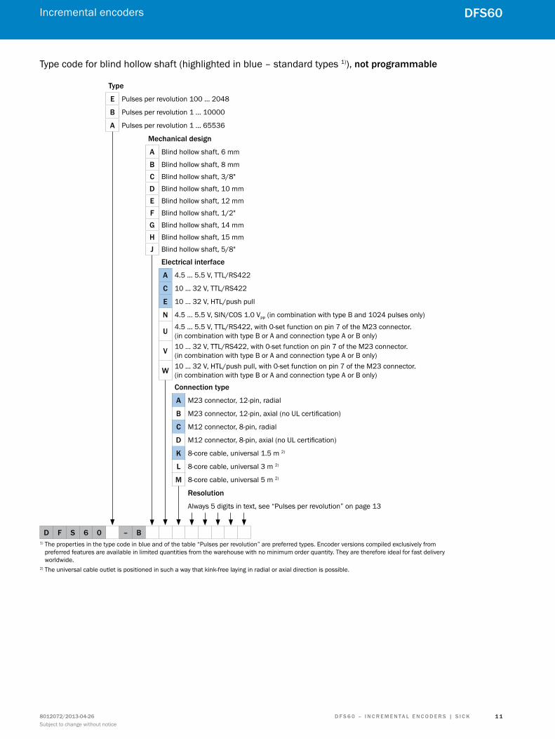
Type code for blind hollow shaft (highlighted in blue – standard types 1)), not programmable
type
E Pulses per revolution 100 ... 2048
B Pulses per revolution 1 ... 10000
a Pulses per revolution 1 ... 65536
mechanical design
a Blind hollow shaft, 6 mm
B Blind hollow shaft, 8 mm
c Blind hollow shaft, 3/8"
D Blind hollow shaft, 10 mm
E Blind hollow shaft, 12 mm
F Blind hollow shaft, 1/2"
G Blind hollow shaft, 14 mm
H Blind hollow shaft, 15 mm
J Blind hollow shaft, 5/8"
Electrical interface
a 4.5 … 5.5 V, TTL/RS422
c 10 … 32 V, TTL/RS422
E 10 … 32 V, HTL/push pull
n 4.5 ... 5.5 V, SIN/COS 1.0 VPP (in combination with type B and 1024 pulses only)
u 4.5 … 5.5 V, TTL/RS422, with 0-set function on pin 7 of the M23 connector. (in combination with type B or A and connection type A or B only)
V 10 … 32 V, TTL/RS422, with 0-set function on pin 7 of the M23 connector. (in combination with type B or A and connection type A or B only)
W 10 … 32 V, HTL/push pull, with 0-set function on pin 7 of the M23 connector. (in combination with type B or A and connection type A or B only)
connection type
a M23 connector, 12-pin, radial
B M23 connector, 12-pin, axial (no UL certification)
c M12 connector, 8-pin, radial
D M12 connector, 8-pin, axial (no UL certification)
K 8-core cable, universal 1.5 m 2)
l 8-core cable, universal 3 m 2)
m 8-core cable, universal 5 m 2)
resolution
Always 5 digits in text, see “Pulses per revolution” on page 13
D F S 6 0 – B 1) The properties in the type code in blue and of the table “Pulses per revolution” are preferred types. Encoder versions compiled exclusively from
preferred features are available in limited quantities from the warehouse with no minimum order quantity. They are therefore ideal for fast delivery worldwide.
2) The universal cable outlet is positioned in such a way that kink-free laying in radial or axial direction is possible.

Incremental encoders
1 2
DFS60
D F S 6 0 – I n c r E m E n ta l E n c o D E r S | S I c K 8012072/2013-04-26Subject to change without notice
Type code for through hollow shaft (highlighted in blue – standard types 1)), not programmable
type
E Pulses per revolution 100 ... 2048
B Pulses per revolution 1 ... 10000
a Pulses per revolution 1 ... 65536
mechanical design
a Metal through hollow shaft, 6 mm
B Metal through hollow shaft, 8 mm
c Metal through hollow shaft, 3/8"
D Metal through hollow shaft, 10 mm
E Metal through hollow shaft, 12 mm
F Metal through hollow shaft, 1/2"
G Metal through hollow shaft, 14 mm
H Metal through hollow shaft, 15 mm
J Metal through hollow shaft, 5/8"
Electrical interface
a 4.5 … 5.5 V, TTL/RS422
c 10 … 32 V, TTL/RS422
E 10 … 32 V, HTL/push pull
n 4.5 ... 5.5 V, SIN/COS 1.0 VPP (in combination with type B and 1024 pulses only)
u 4.5 … 5.5 V, TTL/RS422, with 0-set function on pin 7 of the M23 connector. (in combination with type B or A and connection type A or B only)
V 10 … 32 V, TTL/RS422, with 0-set function on pin 7 of the M23 connector. (in combination with type B or A and connection type A or B only)
W 10 … 32 V, HTL/push pull, with 0-set function on pin 7 of the M23 connector. (in combination with type B or A and connection type A or B only)
connection type
a M23 connector, 12-pin, radial
c M12 connector, 8-pin, radial
K 8-core cable, universal 1.5 m 2)
l 8-core cable, universal 3 m 2)
m 8-core cable, universal 5 m 2)
resolution
Always 5 digits in text, see “Pulses per revolution” on page 13
D F S 6 0 – t1) The properties in the type code in blue and of the table “Pulses per revolution” are preferred types. Encoder versions compiled exclusively from
preferred features are available in limited quantities from the warehouse with no minimum order quantity. They are therefore ideal for fast delivery worldwide.
2) The universal cable outlet is positioned in such a way that kink-free laying in radial or axial direction is possible.

Incremental encoders
1 3
DFS60
D F S 6 0 – I n c r E m E n ta l E n c o D E r S | S I c K8012072/2013-04-26Subject to change without notice
Pulses per revolution (highlighted in blue – standard types 1))
E B a
Pulses per revolution 2) 00100 00100 00100
00200 00200 00200
00250 00250 00250
00256 00300 00300
00314 00314 00314
00360 00360 00360
00500 00500 00500
00512 00512 00512
00720 00720 00720
01000 01000 01000
01024 01024 01024
01250 01250 01250
02000 02000 02000
02048 02048 02048
02500 02500
03600 03600
04000 04000
04096 04096
05000 05000
07200 07200
08192 08192
10000 10000
16384
32768
65536
Others on request Others on request1) The properties in the type code in blue and of the table “Pulses per revolution” are preferred types. Encoder versions compiled exclusively from preferred features
are available in limited quantities from the warehouse with no minimum order quantity. They are therefore ideal for fast delivery worldwide. 2) The electrical interface N (Sin/Cox 1.0 VPP) can only be ordered with 1024 pulses per revolution.

Incremental encoders
1 4
DFS60
D F S 6 0 – I n c r E m E n ta l E n c o D E r S | S I c K 8012072/2013-04-26Subject to change without notice
Dimensional drawingsdimensions in mm (inch)
Face mount flangeCable outlet
Ø 60
(2.3
6)
Ø 0.05 B
0.03 A
B
C
Ø 36
(1.4
2) f8
Ø 10
(0.3
9) f7
9(0
.35)
18(0.71)
19±0.3(0.75)
43.1 (1.70)
A
10 (0.39)
Ø 0.1 A
3 x 1
20°
3 x
M4
(6-d
eep)
Ø 48
±0.0
5 (1
.89)
Ø 0.05 C
A
General tolerances as per DIN ISO 2768-mk1 Cable diameter = 5.6 ± 0.2 mm; bend radius R = 30 mm
Radial connector outlet M12 and M23
7.75(0.31)
M23 x 1
26.1
(1.0
3)
13(0.51)
Ø 0.05 B
Ø 36
(1.4
2) f8
Ø 10
(0.3
9) f7
0.03 A
B
C
9(0
.35)
Ø 60
(2.3
6)
40.1 (1.58)10 (0.39)
A
0.1 A
14.5
(0.5
7)
M12 x 1
(3x) 120°
3 x
M4
(6-d
eep)
Ø 48
±0.0
5 (1
.89)
Ø 0.1 C
18(0.71)
19±0.3(0.75)
25°±2°
A
General tolerances as per DIN ISO 2768-mk

Incremental encoders
1 5
DFS60
D F S 6 0 – I n c r E m E n ta l E n c o D E r S | S I c K8012072/2013-04-26Subject to change without notice
Axial connector outlet M12 and M23
0.1 A
0.03 A
Ø 0.05 A
C
B
A
Ø 0.1 C
Ø 36
f8 (1
.42) Ø 10
f7(0
.39)
9(0
.35) 18
(0.71)
19±0.3(0.75)
57(2.24)
12(0.47) M
12 x
1
X1
Connector orientation
X1 X2
21.1(0.83)
M23
x 1
X2
Ø 60
(2.3
6)Ø
48±0
.1 (1
.89)
25°±2°
3 x
120°
3 x
M4
6 0.
24 d
eep
General tolerances as per DIN ISO 2768-mk
Servo flangeCable outlet
Ø 0.05 B
C
B
A
Ø 0.05 C
58±0
.1 (2
.28)
51.5
–0.2
(2.0
3)
Ø 50
(1.9
7) f8
Ø 6
(0.2
4) f7
9.5(0.37)
5.7
(0.2
2)
10±0.3(0.39)
10+0.1
(0.39)43.1 (1.70)
Ø 60
(2.3
6)
4+0.1 (0.16)
3(0.12)
0.1 A
0.1 A
3 x 1
20° 3
x M
4(6
-dee
p)Ø
42±0
.05
(1.6
5)A
General tolerances as per DIN ISO 2768-mk1 Cable diameter = 5.6 ± 0.2 mm; bend radius R = 30 mm

Incremental encoders
1 6
DFS60
D F S 6 0 – I n c r E m E n ta l E n c o D E r S | S I c K 8012072/2013-04-26Subject to change without notice
Radial connector outlet M12 and M23
Ø 0.05 B
C
0.03 A
B
A
0.1 A
0.1 A
Ø 0.1 C
58±0
.1 (2
.28)
51.5
–0.2
(2.0
3)Ø
50 (1
.97)
f8Ø
6 (0
.24)
f75.
7 (0
.22)
9.5(0.37)
10±0.3(0.39)
10+0.1
(0.39)
4+0.1 (0.16)
3(0.12)
7.75(0.31)
Ø 60
(2.3
6)
M12 x 140.1 (1.58)
14.5
(0.5
7)
26.1
(1.0
3)
13(0.51)
M23 x 1
Ø 42
±0.0
5 (1
.65)
3 x
M4
(6-d
eep) 3 x 120°
25°±2°
A
General tolerances as per DIN ISO 2768-mk
Axial connector outlet M12 and M23
4+0.1(0.16)
3(0.12)
0.1 A
0.1 AC
A12
(0.47) M12
x 1
X1
57 (2.24)
10+0.1
(0.39)Ø 0.05
0.03 A
B
B
Ø 58
±0.1
(2.2
3)Ø
51.5
–0.2
(2.0
3)Ø
50 (1
.97)
f8 Ø 6
f7(0
.24) 5.
7(0
.22)
9.5(0.37)
10±0.3(0.39)
Connector orientation
X1 X2
21.1(0.83)
X2
M23
x 1
3 x
120
°
3 x M46 (0.24) deep
25°±2°
Ø 42
(1.6
5)Ø
60 (2
.36)
Ø 0.1 C
General tolerances as per DIN ISO 2768-mk
Mounting suggestion for small servo clamp part no. 2029166
3 x 120°
Ø 68 (2.68)
Mounting suggestion for half-shell servo clamp part no. 2029165
4 x 90°
Ø 71 (2.80)

Incremental encoders
1 7
DFS60
D F S 6 0 – I n c r E m E n ta l E n c o D E r S | S I c K8012072/2013-04-26Subject to change without notice
Blind hollow shaftCable outlet
45.5 (1.79)
9.4 (0.37)
3.4 (0.13)
Ø X
F7
47 (1
.85)
Ø 35
(1.3
8)
Ø 60
(2.3
6)
2.5(0.10)
min. 15 (0.59)
Ø 3.
2+0.
1
(0.1
3) 20°
20(0.79)
Ø 63
±0.2
(2.4
8)72
±0.3
(2.8
3)
max. 42 (1.65)
A
Ø x
j7
General tolerances as per DIN ISO 2768-mk1 Cable diameter = 5.6 ± 0.2 mm; bend radius R = 30 mmXF7 = hollow shaft diameter, see table belowxj7 = shaft diameter, on the customer side
Diameter XF7
Blind hollow shaft 6 mm
Blind hollow shaft 8 mm
Blind hollow shaft 3/8"
Blind hollow shaft 10 mm
Blind hollow shaft 12 mm
Blind hollow shaft 1/2"
Blind hollow shaft 14 mm
Blind hollow shaft 15 mm
Blind hollow shaft 5/8"

Incremental encoders
1 8
DFS60
D F S 6 0 – I n c r E m E n ta l E n c o D E r S | S I c K 8012072/2013-04-26Subject to change without notice
Radial connector outlet M12 and M23
45.5 (1.79)
9.4 (0.37)
3.4 (0.13)
Ø X
F7
2.5 (0.10)
Ø 60
(2.3
6)
min. 15 (0.59)
max. 42 (1.65)
14.5
(0.5
7)
M12 x 1
Ø 32
.6 (1
.28)
7.75(0.31)
26.1
(1.0
3)
13(0.51)
M23 x 1
72±0.3 (2.83)
Ø 3.2+0.1 (0.13)
20°
20 (0
.79)
47 (1.85)
Ø 63±0.2 (2.48)
A
Ø x
j7
General tolerances as per DIN ISO 2768-mkXF7 = hollow shaft diameter, see table belowxj7 = shaft diameter, on the customer side
Diameter XF7
Blind hollow shaft 6 mm
Blind hollow shaft 8 mm
Blind hollow shaft 3/8"
Blind hollow shaft 10 mm
Blind hollow shaft 12 mm
Blind hollow shaft 1/2"
Blind hollow shaft 14 mm
Blind hollow shaft 15 mm
Blind hollow shaft 5/8"

Incremental encoders
1 9
DFS60
D F S 6 0 – I n c r E m E n ta l E n c o D E r S | S I c K8012072/2013-04-26Subject to change without notice
Axial connector outlet M12 and M23
Ø x
j7
Customer side
3.4(0.13)
Ø X
F7
9.4(0.37) 56.9 (2.24)
12(0.47) M
12 x
1
X1
Ø 3.2+0.1
(0.13)
20°
47 (1.85)72 (2.83)
20 (0
.79)
Ø 60
(2.3
6)Ø
63 (2
.48)
Connector orientation
X1 X2X2
M23
x 1
21.1(0.83)
min. 15(0.59)
max. 40 (1.57)
General tolerances as per DIN ISO 2768-mkXF7 = hollow shaft diameter, see table belowxj7 = shaft diameter, on the customer side
Diameter XF7
Blind hollow shaft 6 mm
Blind hollow shaft 8 mm
Blind hollow shaft 3/8"
Blind hollow shaft 10 mm
Blind hollow shaft 12 mm
Blind hollow shaft 1/2"
Blind hollow shaft 14 mm
Blind hollow shaft 15 mm
Blind hollow shaft 5/8"

Incremental encoders
2 0
DFS60
D F S 6 0 – I n c r E m E n ta l E n c o D E r S | S I c K 8012072/2013-04-26Subject to change without notice
Through hollow shaft Metal, cable outlet
9.4 (0.37)
3.4 (0.13)
43 (1.69)
Ø X
F7
47 (1
.85)
min. 15 (0.59)
Ø 3.
2+0.
1
(0.1
3) 20°
20(0.79)
Ø 63
±0.2
(2.4
8)72
±0.3
(2.8
3)
Ø 60
(2.3
6)
A
Ø x
j7
Customer side
General tolerances as per DIN ISO 2768-mk1 Cable diameter = 5.6 ± 0.2 mm; bend radius R = 30 mmXF7 = hollow shaft diameter, see table belowxj7 = shaft diameter, on the customer side
Diameter XF7
Blind hollow shaft 6 mm
Blind hollow shaft 8 mm
Blind hollow shaft 3/8"
Blind hollow shaft 10 mm
Blind hollow shaft 12 mm
Blind hollow shaft 1/2"
Blind hollow shaft 14 mm
Blind hollow shaft 15 mm
Blind hollow shaft 5/8"

Incremental encoders
2 1
DFS60
D F S 6 0 – I n c r E m E n ta l E n c o D E r S | S I c K8012072/2013-04-26Subject to change without notice
Metal, radial connector outlet M12 and M23
9.4 (0.37)
3.4 (0.13)
43 (1.69)
Ø X
F7
min. 15 (0.59)
Ø 60
(2.3
6)
7.75(0.31)
14.5
(0.5
7)
M12 x 1
26.1
(1.0
3)
13(0.51)
M23 x 1
72±0.3 (2.83)
Ø 3.2+0.1 (0.13)
20°20
(0.7
9)
47 (1.85)
Ø 63±0.2 (2.48)
A
Customer side
Ø x
j7
General tolerances as per DIN ISO 2768-mkXF7 = hollow shaft diameter, see table belowxj7 = shaft diameter, on the customer side
Diameter XF7
Blind hollow shaft 6 mm
Blind hollow shaft 8 mm
Blind hollow shaft 3/8"
Blind hollow shaft 10 mm
Blind hollow shaft 12 mm
Blind hollow shaft 1/2"
Blind hollow shaft 14 mm
Blind hollow shaft 15 mm
Blind hollow shaft 5/8"

Incremental encoders
2 2
DFS60
D F S 6 0 – I n c r E m E n ta l E n c o D E r S | S I c K 8012072/2013-04-26Subject to change without notice
PIn and core assignment8-core cable
View of M12 device connector on encoder View of M23 device connector on encoder
PIn, 8-pin, m12 connector
PIn, 12-pin, m23 connector
core colors of encoders with cable outlet
ttl/Htl signal SIn/coS 1,0 VPP Explanation
1 6 Brown ¯A COS– Signal cable
2 5 White A COS+ Signal cable
3 1 Black ¯B SIN– Signal cable
4 8 Pink B SIN+ Signal cable
5 4 Yellow ¯Z Z Signal cable
6 3 Lilac Z Z Signal cable
7 10 Blue GND GND Ground connection of the encoder
8 12 Red +US +US Supply voltage (volt-free to housing)
– 9 – N.C. N.C. Not assigned
– 2 – N.C. N.C. Not assigned
– 11 – N.C. N.C. Not assigned
– 7 1) – 0-SET 1) N.C. Zeropulse Teach 1)
Shield Shield Shield Shield ShieldShield connected to housing on side of encoder.Connected to ground on side of control.
1) For electrical interfaces only: M, U, V, W with 0-SET function on PIN 7 on M23 plug. The 0-SET input is used to set the zero pulse on the current shaft position. If the 0-SET input is applied to US for longer than 250 ms, after it has was open for at least 1,000 ms or applied to GND, the current shaft position is assigned the zero pulse signal “Z”.

Incremental encoders
2 3
DFS60
D F S 6 0 – I n c r E m E n ta l E n c o D E r S | S I c K8012072/2013-04-26Subject to change without notice
Interfaces
Signal outputs for electrical interfaces TTL and HTL
Cw looking towards the encoder shaft pointing towards “A” , see dimensional drawing.
Supply voltage output
4.5 ... 5.5 V TTL
10 ... 32 V TTL
10 ... 32 V HTL
Electrical zero pulse width 90°, 180° or 270° pro-grammable. Width of the zero pulse in relation to a pulse period.
Cw looking towards the encoder shaft pointing towards “A”, see dimensional drawing.
Supply voltage output
4.5 ... 32 V HTL/TTL programmable
Mechanical zero pulse width 1° to 359° program-mable. Width of the zero pulse in relation to a mechanical revolution of the shaft.
A
B
1°–359°Z
1 turn360° mech.

Incremental encoders
2 4
DFS60
D F S 6 0 – I n c r E m E n ta l E n c o D E r S | S I c K 8012072/2013-04-26Subject to change without notice
Electrical interfaces SIN/COS 1.0 VPP
Power supply output
4.5 ... 5.5 V Sine 0.5 Vpp
Signal before differential generation at load 120 Ω and US = 5 V Signal diagram for clockwise rotation of the shaft looking in direction “A” (shaft)
2.5 V
2.5 V
2.9 V
1.75 V
2.9 V
1.75 V
0.5 V
0.5 V
360° el.
90° el.
Z
COS+ COS–
SIN+ SIN–
Z
Interface signals Sin+, SIn–, coS+, coS– Signal before differential generation at load 120 Ω Signal offset
Analog differential 0.5 Vpp ± 20 % 2.5 V ± 10 %
Interface signals Z, Z Signal before differential generation at load 120 Ω
Digital differential Low: 1.75 V ± 15 %; High: 2.9 V ± 15 %
Signal after differential generation at load 120 Ω and US = 5 V Signal diagram for clockwise rotation of the shaft looking in direction “A” (shaft)
COS+ – COS–
SIN+ – SIN–
Z – Z
0 V
0 V
0 V
1 V
1 V
2.3 V
360° el.
90° el.

Incremental encoders
2 5
DFS60
D F S 6 0 – I n c r E m E n ta l E n c o D E r S | S I c K8012072/2013-04-26Subject to change without notice
accessoriesdimensions in mm (inch)
Programming Tools
Description model name Part no.
Programming tool for connection to standard PC or notebook via USB port PGT-08-S 1036616
The PGT-10-S is an intuitively operated standalone programming device for SICK incremental encoders. Its low weight and compact dimensions make it portable and usable everywhere.
PGT-10-S 1052967
Adapter cable for programming toolsThe following adapter cables are required to program the SICK incremental encoders.
Description model name Part no.
Adapter cable for incremental programming tool with SUB-D 9-pin cable plug and M12 8-pin cable socket, pre-wired with 8-core cable, 4 x 2 x 0.08 mm², shielded, suitable for incremental encoder with M12 plug connector
DSL-2D08-G0M5AC3 2046579
Adapter cable for incremental programming tool with SUB-D 9-pin cable plug and M23 12-pin cable socket, pre-wired with 8-core cable, 4 x 2 x 0.08 mm², shielded, suitable for incremental encoder with M23 plug connector
DSL-3D08-G0M5AC3 2046580
Adapter cable for incremental programming tool with SUB-D 9-pin cable plug, shielded, suitable for incremental encoder with cable outlet DSL-0D08-G0M5AC3 2061739
WarnInG: Programming of the incremental encoders using the adapter cables for the absolute encoders will destroy the incre-mental encoders. Please ensure correct use!
Incremental encoders
2 6
DFS60
D F S 6 0 – I n c r E m E n ta l E n c o D E r S | S I c K 8012072/2013-04-26Subject to change without notice
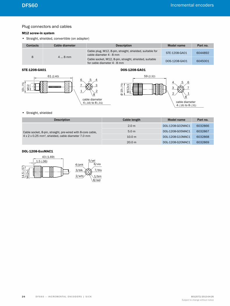
Plug connectors and cablesM12 screw-in system
• Straight, shielded, convertible (on adapter)
contacts cable diameter Description model name Part no.
8 4 ... 8 mm
Cable plug, M12, 8-pin, straight, shielded, suitable for cable diameter 4 - 8 mm STE-1208-GA01 6044892
Cable socket, M12, 8-pin, straight, shielded, suitable for cable diameter 4 - 8 mm DOS-1208-GA01 6045001
STE-1208-GA01 DOS-1208-GA01
• Straight, shielded
Description cable length model name Part no.
Cable socket, 8-pin, straight, pre-wired with 8-core cable, 4 x 2 x 0.25 mm², shielded, cable diameter 7.0 mm
2.0 m DOL-1208-G02MAC1 6032866
5.0 m DOL-1208-G05MAC1 6032867
10.0 m DOL-1208-G10MAC1 6032868
20.0 m DOL-1208-G20MAC1 6032869
DOL-1208-GxxMAC1
1/brn2/wht
3/blk
4/pnk5/yel
6/vio
7/blu
8/red
Incremental encoders
2 7
DFS60
D F S 6 0 – I n c r E m E n ta l E n c o D E r S | S I c K8012072/2013-04-26Subject to change without notice
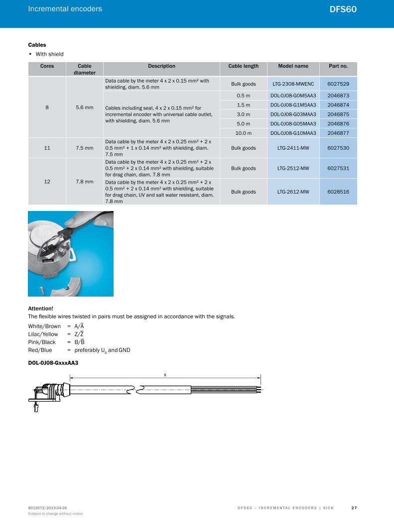
Cables • With shield
cores cable diameter
Description cable length model name Part no.
8 5.6 mm
Data cable by the meter 4 x 2 x 0.15 mm² with shielding, diam. 5.6 mm Bulk goods LTG-2308-MWENC 6027529
Cables including seal, 4 x 2 x 0.15 mm² for incremental encoder with universal cable outlet, with shielding, diam. 5.6 mm
0.5 m DOL-0J08-G0M5AA3 2046873
1.5 m DOL-0J08-G1M5AA3 2046874
3.0 m DOL-0J08-G03MAA3 2046875
5.0 m DOL-0J08-G05MAA3 2046876
10.0 m DOL-0J08-G10MAA3 2046877
11 7.5 mmData cable by the meter 4 x 2 x 0.25 mm² + 2 x 0.5 mm² + 1 x 0.14 mm² with shielding, diam. 7.5 mm
Bulk goods LTG-2411-MW 6027530
12 7.8 mm
Data cable by the meter 4 x 2 x 0.25 mm² + 2 x 0.5 mm² + 2 x 0.14 mm² with shielding, suitable for drag chain, diam. 7.8 mm
Bulk goods LTG-2512-MW 6027531
Data cable by the meter 4 x 2 x 0.25 mm² + 2 x 0.5 mm² + 2 x 0.14 mm² with shielding, suitable for drag chain, UV and salt water resistant, diam. 7.8 mm
Bulk goods LTG-2612-MW 6028516
attention! The flexible wires twisted in pairs must be assigned in accordance with the signals.
White/Brown = A/A Lilac/Yellow = Z/Z Pink/Black = B/B Red/Blue = preferably US and GND
DOL-0J08-GxxxAA3
x

Incremental encoders
2 8
DFS60
D F S 6 0 – I n c r E m E n ta l E n c o D E r S | S I c K 8012072/2013-04-26Subject to change without notice
Round screw system M23 • Straight, shielded
Description cable length model name Part no.
M23 cable plug, 12-pin, straight, 8-core cable, including seal, 4 x 2 x 0.15 mm2, with shielding, cable diameter 5.6 mm
0.35 m STL-2312-GM35AA3 2061621
1.0 m STL-2312-G01MAA3 2061622
2.0 m STL-2312-G02MAA3 2061504
STL-2312-GM35AA3 STL-2312-GO1MAA3 STL-2312-GO2MAA3
Counter nutSW30
57±0.2 (2.24)
X
28 (1
.10)
PIN allocation connector M23
PIn Signal ttl, Htl Signal sine 1.0 Vpp
1 B SIN–
2 Not connected Not connected
3 Z Z
4 Z Z
5 A COS+
6 A COS–
7 Not connected Not connected
8 B SIN+
9 Not connected Not connected
10 GND GND
11 Not connected Not connected
12 US US
Shield Shield 1) Shield 1)
attention!
The flexible wires twisted in pairs must be assigned in accor-dance with the signals.
White/Brown = A/A or COS+/COS– Lilac/Yellow = Z/Z Pink/Black = B/B or SIN+/ SIN– Red/Blue = preferably US and GND
1) Shield connected to housing on side of encoder. Connected to ground on side of control.
attention! In combination with the electrical interfaces A, C, E and P only.

Incremental encoders
2 9
DFS60
D F S 6 0 – I n c r E m E n ta l E n c o D E r S | S I c K8012072/2013-04-26Subject to change without notice
M23 screw-in system • Straight, shielded
contacts Description model name Part no.
12Cable plug, M23, 12-pin, straight, shielded, suitable for cable diameter 5.5 - 10.5 mm STE-2312-G 6027537
Cable socket, M23, 12-pin, straight, shielded, suitable for cable diameter 5.5 - 10.5 mm DOS-2312-G 6027538
STE-2312-G
General tolerances as per DIN ISO 2768-mk
DOS-2312-G
General tolerances as per DIN ISO 2768-mk
Description cable length model name Part no.
Cable socket, M23, 12-pin, straight, pre-wired with 11-core cable, 4 x 2 x 0.25 mm² + 2 x 0.5 mm² + 1 x 0.14 mm², shielded, cable diameter 7.8 mm 1)
2.0 m DOL-2312-G02MLA3 2030682
7.0 m DOL-2312-G07MLA3 2030685
10.0 m DOL-2312-G10MLA3 2030688
15.0 m DOL-2312-G15MLA3 2030692
20.0 m DOL-2312-G20MLA3 2030695
25.0 m DOL-2312-G25MLA3 2030699
30.0 m DOL-2312-G30MLA3 20307021) Warning! Only in combination with the electrical interfaces A, C, E and P.
Description cable length model name Part no.
Cable socket, M23, 12-pin, straight, 11-core cable, 4 x 2 x 0.25 mm² + 2 x 0.5 mm² + 1 x 0.14 mm², shielded, cable diameter 7.8 mm 1)
1.5 m DOL-2312-G1M5MA3 2029212
3.0 m DOL-2312-G03MMA3 2029213
5.0 m DOL-2312-G05MMA3 2029214
10.0 m DOL-2312-G10MMA3 2029215
20.0 m DOL-2312-G20MMA3 2029216
30.0 m DOL-2312-G30MMA3 20292171) Warning! Only in combination with the electrical interfaces A, C, E and P.
Incremental encoders
3 0
DFS60
D F S 6 0 – I n c r E m E n ta l E n c o D E r S | S I c K 8012072/2013-04-26Subject to change without notice
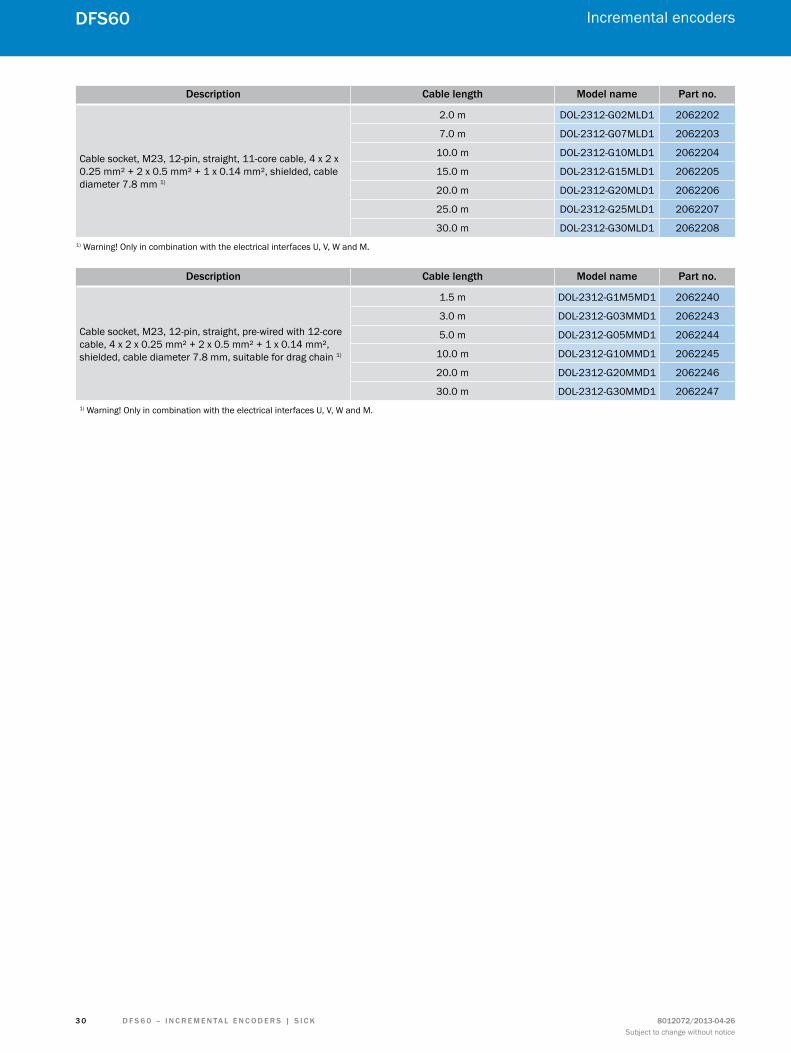
Description cable length model name Part no.
Cable socket, M23, 12-pin, straight, 11-core cable, 4 x 2 x 0.25 mm² + 2 x 0.5 mm² + 1 x 0.14 mm², shielded, cable diameter 7.8 mm 1)
2.0 m DOL-2312-G02MLD1 2062202
7.0 m DOL-2312-G07MLD1 2062203
10.0 m DOL-2312-G10MLD1 2062204
15.0 m DOL-2312-G15MLD1 2062205
20.0 m DOL-2312-G20MLD1 2062206
25.0 m DOL-2312-G25MLD1 2062207
30.0 m DOL-2312-G30MLD1 20622081) Warning! Only in combination with the electrical interfaces U, V, W and M.
Description cable length model name Part no.
Cable socket, M23, 12-pin, straight, pre-wired with 12-core cable, 4 x 2 x 0.25 mm² + 2 x 0.5 mm² + 1 x 0.14 mm², shielded, cable diameter 7.8 mm, suitable for drag chain 1)
1.5 m DOL-2312-G1M5MD1 2062240
3.0 m DOL-2312-G03MMD1 2062243
5.0 m DOL-2312-G05MMD1 2062244
10.0 m DOL-2312-G10MMD1 2062245
20.0 m DOL-2312-G20MMD1 2062246
30.0 m DOL-2312-G30MMD1 20622471) Warning! Only in combination with the electrical interfaces U, V, W and M.

Incremental encoders
3 1
DFS60
D F S 6 0 – I n c r E m E n ta l E n c o D E r S | S I c K8012072/2013-04-26Subject to change without notice
Shaft adaptationCouplings
• Bellow coupling, max. shaft offset radially ± 0.3 mm, axially 0.4 mm, angle ± 4 degrees, torsion spring stiffness of 120 Nm/rad, stainless steel bellow, aluminum hub.
Description model name Part no.
Bellows coupling with hole diameter combination 6 mm x 6 mm, maximum shaft offset, radial ± 0.3 mm, axial ± 0.4 mm, angle ± 4°, torsion spring stiffness 130 Nm/rad, material: stainless steel bellows, aluminum hub
KUP-0606-B 5312981
Bellows coupling with hole diameter combination 6 mm x 10 mm, maximum shaft offset, radial ± 0.3 mm, axial ± 0.4 mm, angle ± 4°, torsion spring stiffness 130 Nm/rad; material: stainless steel bellows, aluminum hub
KUP-0610-B 5312982
Bellows coupling with hole diameter combination 10 mm x 10 mm, maximum shaft offset, radial ± 0.3 mm, axial ± 0.4 mm, angle ± 4°, torsion spring stiffness 130 Nm/rad; material: stainless steel bellows, aluminum hub
KUP-1010-B 5312983
Bellows coupling with hole diameter combination 10 mm x 12 mm, maximum shaft offset, radial ± 0.3 mm, axial ± 0.4 mm, angle ± 4°, torsion spring stiffness 130 Nm/rad; material: stainless steel bellows, aluminum hub
KUP-1012-B 5312984
KUP-0606-B KUP-0610-B KUP-1010-B
Cheese-head screwM2.5 x 8, DIN 912 A2
21±1 (0.83) 29±1 (1.14)
Ø d1
H8
Ø d2
H8
KUP-1012-B
Cheese-head screwM2.5 x 8, DIN 912 A2
24 (0.94) 29±1 (1.14)Ø
d1 H
8
Ø d2
H8
• Spring-disc coupling, max. shaft offset radially ± 0.3 mm, axially 0.4 mm, angle ± 2.5 degrees, torsion spring stiffness of 50 Nm/rad, aluminum flange, plastic spring washer glass-fiber reinforced.
Description model name Part no.
Spring washer coupling with hole diameter combination 6 mm x 10 mm, maximum shaft offset, radial ± 0.3 mm, axial ± 0.4 mm, angle ± 2.5°, torsion spring stiffness 30 Nm/rad; material: aluminum flange, glass-fiber reinforced polyamide membrane and hardened steel coupling pin
KUP-0610-F 5312985
Spring washer coupling with hole diameter combination 10 mm x 10 mm, maximum shaft offset, radial ± 0.3 mm, axial ± 0.4 mm, angle ± 2.5°, torsion spring stiffness 30 Nm/rad; material: aluminum flange, glass-fiber reinforced polyamide membrane and hardened steel coupling pin
KUP-1010-F 5312986
KUP-0610-F KUP-1010-F
Ø d2
H8
Ø d1
H8
22 (0.87)
Ø 30
(1.1
8)

Incremental encoders
3 2
DFS60
D F S 6 0 – I n c r E m E n ta l E n c o D E r S | S I c K 8012072/2013-04-26Subject to change without notice
Insulating shaft connection
outside diameter Inside diameter model name Part no.
10 mm 8 mm Insulating sleeve 8 x 10 PEEK 2065642
12 mm 10 mm Insulating sleeve 10 x 12 PEEK 2064571
14 mm 12 mm Insulating sleeve 12 x 14 PEEK 2064573
15 mm 12.7 mm Insulating sleeve 12,7 x 15 PEEK 2064572
Insulating sleeve 8 x 10 PEEK
A
Ø 8
(0.3
1) G
7
42.7–0.1 (1.68)
Ø 10
(0.3
9) j7
Ø 15
(0.5
9)
1(0.04)
Insulating sleeve 10 x 12 PEEK
Ø 15
(0.5
9)
Ø 10
(0.3
9) G
7
1(0.04)
42.7–0.1 (1.68)
Ø 12
(0.4
7) j7
A
Insulating sleeve 12 x 14 PEEK
A
Ø 12
(0.4
7) G
7
Ø 14
(0.5
5) j7
42.7–0.1 (1.68)
Ø 16
(0.6
3)
1(0.04)
Insulating sleeve 12,7 x 15 PEEK
Ø 12
.7 (0
.50)
G7
Ø 15
(0.5
9) j7
42.7–0.1 (1.68)
Ø 16
(0.6
3)
1(0.04)
A
The diameter of the shaft provided by the customer must be in fit j7.
Clamping ring
Description model name Part no.
Clamping ring metal, accessory for hollow shaft encoder BEF-KR-M 2064709
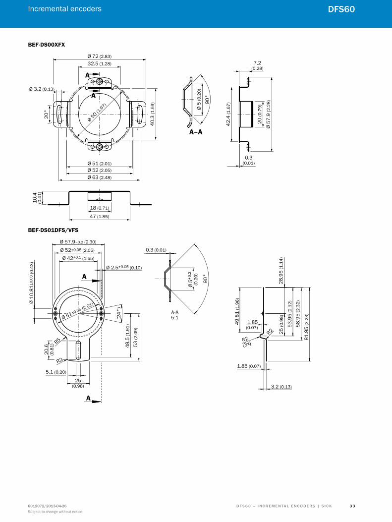
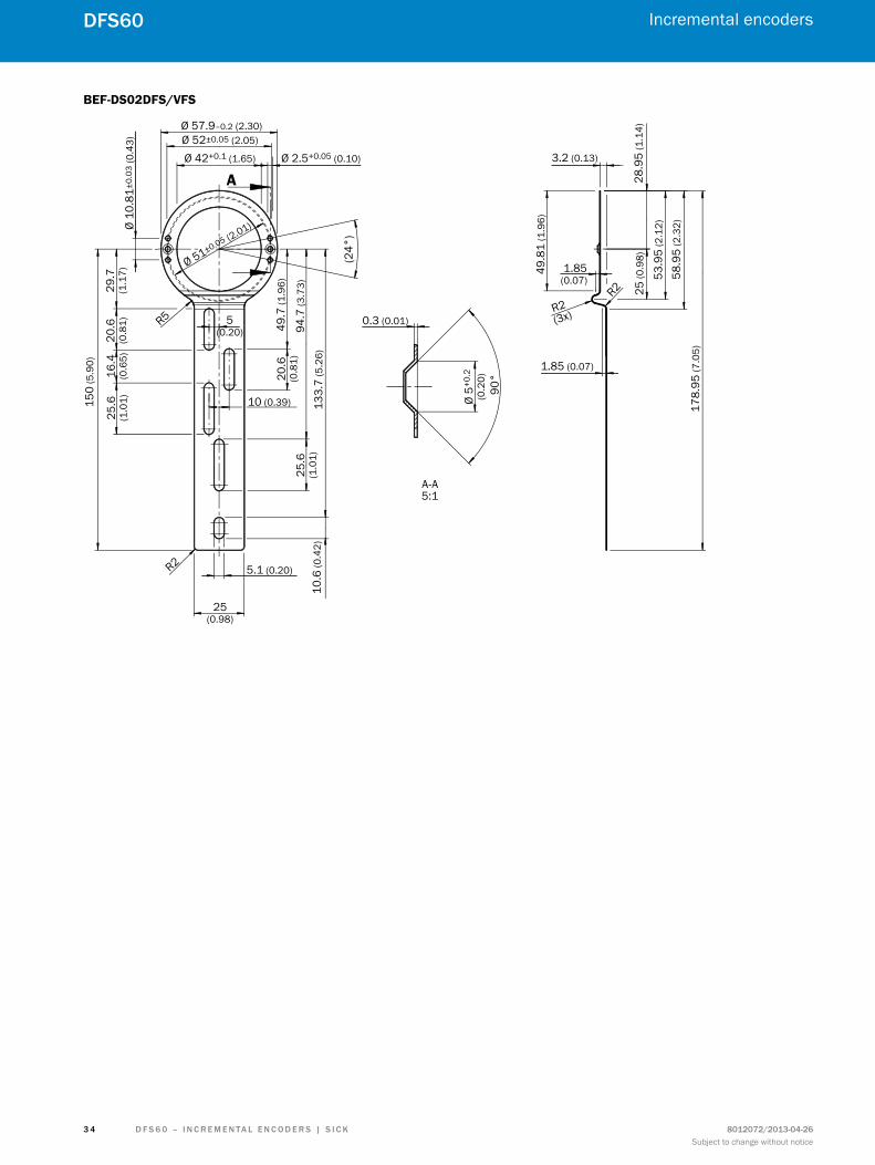
Torque support
Description model name Part no.
Standard torque support BEF-DS00XFX 2056812
Torque support, one-sided, 81 mm long with slot BEF-DS01DFS/VFS 2047428
Torque support, one-sided, 179 mm long with slots BEF-DS02DFS/VFS 2047430
Torque support, one-sided, 248 mm long with slots BEF-DS03DFS/VFS 2047431
Incremental encoders
3 3
DFS60
D F S 6 0 – I n c r E m E n ta l E n c o D E r S | S I c K8012072/2013-04-26Subject to change without notice
BEF-DS00XFX
Ø 5
(0.2
0)
90°
A–A
Ø 72 (2.83)32.5 (1.28)
Ø 50 (1.97)
40.3
(1.5
9)
Ø 51 (2.01)
Ø 3.2 (0.13)
Ø 52 (2.05)Ø 63 (2.48)
20°
10.4
(0.4
1)
18 (0.71)
47 (1.85)
7.2(0.28)
42.4
(1.6
7)
20 (0
.79)
0.3(0.01)
Ø 57
.9 (2
.28)
A
A
BEF-DS01DFS/VFS
Ø 57.9–0.2 (2.30) Ø 52±0.05 (2.05)
Ø 42+0.1 (1.65)
Ø 2.5+0.05 (0.10)
Ø 10
.81±
0.03
(0.4
3)
Ø 51±0.05 (2.01)
(24°
)
R5
R2
20.6
(0.8
1)
5.1 (0.20)
25(0.98)
A
A
48.5
(1.9
1)
53 (2
.09)
0.3 (0.01)
A-A5:1
Ø 5+
0.2
(0.2
0)
90°
49.8
1 (1
.96)
28.9
5 (1
.14)
25 (0
.98)
53.9
5 (2
.12)
58.9
5 (2
.32)
81.9
5 (3
.23)
1.85(0.07)
1.85 (0.07)
3.2 (0.13)
R2(3x)
R2
Incremental encoders
3 4
DFS60
D F S 6 0 – I n c r E m E n ta l E n c o D E r S | S I c K 8012072/2013-04-26Subject to change without notice
BEF-DS02DFS/VFS
49.8
1 (1
.96)
28.9
5 (1
.14)
25 (0
.98)
53.9
5 (2
.12)
58.9
5 (2
.32)
178.
95 (7
.05)
1.85(0.07)
1.85 (0.07)
3.2 (0.13)
R2(3x)
R2
Ø 57.9–0.2 (2.30) Ø 52±0.05 (2.05)
Ø 42+0.1 (1.65) Ø 2.5+0.05 (0.10)
Ø 10
.81±
0.03
(0.4
3)
Ø 51±0.05 (2.01)
R5
(24°
)
A
0.3 (0.01)
A-A5:1
Ø 5+
0.2
(0.2
0)90
°
150
(5.9
0)
29.7
(1.1
7)20
.6(0
.81)
16.4
(0.6
5)25
.6(1
.01)
49.7
(1.9
6)20
.6(0
.81)
10 (0.39)
94.7
(3.7
3)
133.
7 (5
.26)
25.6
(1.0
1)10
.6 (0
.42)
R2 5.1 (0.20)
25(0.98)
5(0.20)

Incremental encoders
3 5
DFS60
D F S 6 0 – I n c r E m E n ta l E n c o D E r S | S I c K8012072/2013-04-26Subject to change without notice
BEF-DS03DFS/VFS
49.8
1 (1
.96)
28.9
5 (1
.14)
25 (0
.98)
53.9
5 (2
.12)
58.9
5 (2
.32)
248.
95 (9
.80)
1.85(0.07)
1.85 (0.07)
3.2 (0.13)
R2(3x)
R2
0.3 (0.01)
0.3 (0.01)
A-A5:1
Ø 5+
0.2
(0.2
0)90
°
Ø 57.9–0.2 (2.30) Ø 52±0.05 (2.05)
Ø 42+0.1 (1.65) Ø 2.5+0.05 (0.10)
Ø 10
.81±
0.02
5 (0
.43)
(24°
)
Ø 51±0.05 (2.01)
70 (2
.76)
100
(3.9
4) R5
20.6
(0.8
1)
220
(8.6
6)
5.55
(0.2
2)
R2 5.1(0.20) 25
(0.98)
117
(4.6
0)
5(0.20)
5(0.20) 25
.6(1
.01)
20.6
(0.8
1) 48.5
(1.9
1)
A
A

Incremental encoders
3 6
DFS60
D F S 6 0 – I n c r E m E n ta l E n c o D E r S | S I c K 8012072/2013-04-26Subject to change without notice
Mechanical adaptersAdaptor flange
adaptations model name Part no.
Flange adapter, adapts face mount flange with 36 mm centering collar to 50 mm servo flange BEF-FA-036-050 2029160
Flange adapter, adapts face mount flange with 36 mm centering collar to 60 mm square mounting plate BEF-FA-036-060REC 2029162
Flange adapter, adapts face mount flange with 36 mm centering collar to 58 mm square mounting plate with shock absorber BEF-FA-036-060RSA 2029163
Flange adapter, adapts face mount flange with 36 mm centering collar to 63 mm square mounting plate BEF-FA-036-063REC 2034225
BEF-FA-036-050
10 +0.1 (0.39) 3 +0.1 (0.12) 4 –0.1 (0.16)
Ø 51
(2.0
0)
Ø 36
H8
(1.4
2)
0.3 +0.1 (0.01)2.3 (0.09)
3 x
90°
58 (2.28)
3 x M4
41
0
5
26
3
50 18 (1.97)
3 x 4.1 +0.1
(0.16)8 +0.1
(0.31)
Rz 6.3
A0.02 A
0.05 A
BEF-FA-036-060REC36 H8 (1.42)4 xR4
4 x
4.5
(0.1
8)
48 (1.89)58 (2.28)
48 (1
.89)
58 (2
.28)
4 (0.16)

Incremental encoders
3 7
DFS60
D F S 6 0 – I n c r E m E n ta l E n c o D E r S | S I c K8012072/2013-04-26Subject to change without notice
BEF-FA-036-060RSA
10 (0.39)
10(0.39)
4 (0.39)
4 x springwasher
4 x hexagonalnut (secure withLoctite 241)
4 x
Ø 10
±0.
3 (0
.39)
4 x
M4
2.8
(0.1
1) d
eep
48 ±0.1 (1.89)
36 H8 (1.42)
58 ±0.2 (2.28)
BEF-FA-036-063REC
A
A
A–A
28°4 x R
4
52.4
±0.
1 (2
.06)
3 x
120°
63 ±0.2 (2.48)
Ø 48
±0.
1 (1
.89)
H8
5 (0.20)
3 x
Ø 8.
6 ±0
.2 (0
.34)
45°
4 x
Ø 5.
5(0
.22)
3 x
Ø 4.
3 (0
.17)
H12
Mounting bells
Description model name Part no.
Mounting bell for servo flange encoder with 50 mm centering collar incl. mounting kit BEF-MG-50 5312987
BEF-MG-50
85.5 ±0.05 (3.25)42
(1.65)10 x 4.5
(0.18)
9 (0.35)68 (2.68)75 (2.95)
90° 30
°30
°25
°
33(1.30)
3.95(0.16)
25.8 (1.02)21.2 (0.83)
0.1
Ø 62
.7 (2
.47)
Ø 58
.7 (2
.31)
Ø 50
.05
±0.0
3(1
.97)
Ø 32
.1(1
.26)
Ø 51
.03
±0.0
3(2
.01)
5.9(0.23)

Incremental encoders
3 8
DFS60
D F S 6 0 – I n c r E m E n ta l E n c o D E r S | S I c K 8012072/2013-04-26Subject to change without notice
Mounting bracket • Mounting bracket incl. mounting kit for encoder with face mount flange
Description model name Part no.
Mounting bracket for encoder with 36 mm centering collar BEF-WF-36 2029164
BEF-WF-36
Ø 48 ±0.1(1.89)2 x 45°
120°
80 (3.15)60 (2.36)
80 (3
.15)
45 (1
.77)
90°
Ø 36
+0.5
(1.4
2)
3.2(0.13)4.
5 (0
.18)
6 (0
.24)
40(1.57)
22 (0.87)
Ø 7 (0.28)
Servo clamps
Description model name Part no.
Servo clamp half-shells (set of 2) for 50 mm centering collar BEF-WG-SF050 2029165
Servo clamps (set of 3), large BEF-WK-SF 2029166
BEF-WG-SF050
4 x
90°
A
A
45°
1 (0.04)
71 ±
0.02
(2.8
0)
81 (3
.19)
5.6 –0.1 (0.22)
2.8 –0.05 (0.11)
Ø 52
.2 (2
.06)
Ø 58
.2 (2
.29)
BEF-WK-SF
11 (0
.43)
14 (0.55)
Ø 7.
4 –0
.1(0
.29)
1 +0.1
(0.04)
Ø 4.
2 (0
.17)
Ø 7–
0.1
(0.2
8)
2.8 –0.1 (0.11)
5.5 –0.1 (0.22)

Incremental encoders
3 9
DFS60
D F S 6 0 – I n c r E m E n ta l E n c o D E r S | S I c K8012072/2013-04-26Subject to change without notice
Bearing block
Description model name Part no.
Bearing block for hollow shaft encoder BEF-FA-B12-010 2042728
Bearing block for servo and face mount flange encoder BEF-FA-LB1210 2044591
BEF-FA-B12-010
10 +0.1 (0.39)30 +0.1
(1.18)
A
3 x 120°
Ø 75 ±0.1 (2.95)Ø 63 (2.48)
20°
3 x
M3
10 (0
.39)
dee
p
0.1 A-B
Ø 69 ±0.2 (2.72)19 ±0.5 (0.75)
18(0.71)
B
0.1 A-B
Ø 36
f8(1
.42)
Ø 10
f6(0
.39)
9(0
.35)
Ø 12
f6 (0
.47)
3 x
M4
10 (0
.39)
dee
p
Ø 48 (1.89)
BEF-FA-LB1210
9(0.35)
68±0
.2 (2
.68)
10 (0.3
9)50 (1.97)
125 (4.92)
15.5(0.49)
1(0.04)
24(0.94)
Ø 15
g7
(0.5
9)
A
Ø 6
f6(0
.24)
0.2 A
36.5 (1.44)12
(0.47)73 (2.87)98 (3.86)
52 (2.05)
28 (1
.10)
40 (1
.57)
Ø 50 H7 (1.97)
56 (2
.20)
6(0
.24)
6 x 8.4 H13(0.33)
90±0
.2 (3
.54)
64±0
.4 (2
.52)
80–0
.2 (3
.15)
31(1.22)
45(1.77)
22(0.87)
20.3(0.80)

Incremental encoders
4 0
DFS60
D F S 6 0 – I n c r E m E n ta l E n c o D E r S | S I c K 8012072/2013-04-26Subject to change without notice
Measuring wheels
Description model name Part no.
Measuring wheel with smooth plastic surface (Hytrel) for 10 mm solid shaft, circumference 200 mm BEF-MR-010020 5312988
Measuring wheel with ridged plastic surface (Hytrel) for 10 mm solid shaft, circumference 200 mm BEF-MR-010020G 5318678
BEF-MR-010020 BEF-MR-010020G
M4
63.66 +0.05–0.1 (2.51)
17.5(0.69)12
(0.47)0.5 (0.02)
18 (0.7
1)
Ø 10
H8
(0.3
9)M
4 x
6 D
IN 9
16
Description model name Part no.
Measuring wheel with smooth plastic surface (Hytrel) for 10 mm solid shaft, circumference 500 mm BEF-MR-010050 5312989
BEF-MR-010050
M5
159.16 (6.27)
33(1.30)
24.5±0.2 (0.96)
0.6 (0.02)
Ø 10
H8
(0.3
9)M
5 x
6 D
IN 9
16
20 (0.7
9)
Incremental encoders
4 1
DFS60
D F S 6 0 – I n c r E m E n ta l E n c o D E r S | S I c K8012072/2013-04-26Subject to change without notice
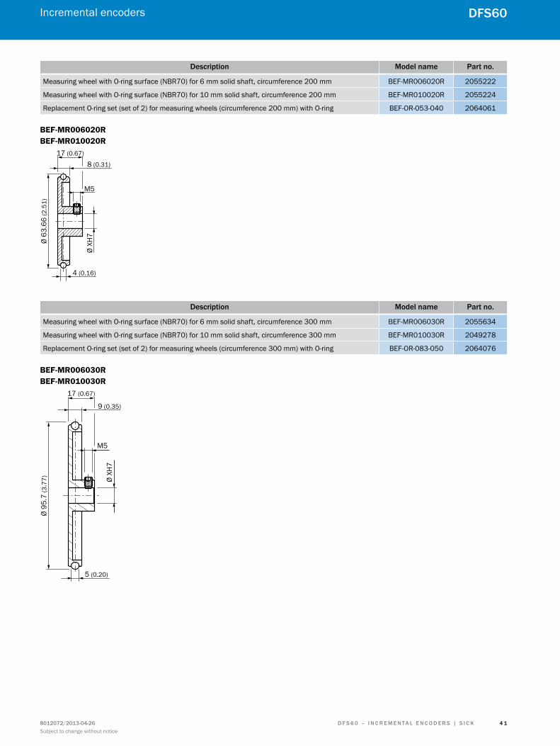
Description model name Part no.
Measuring wheel with O-ring surface (NBR70) for 6 mm solid shaft, circumference 200 mm BEF-MR006020R 2055222
Measuring wheel with O-ring surface (NBR70) for 10 mm solid shaft, circumference 200 mm BEF-MR010020R 2055224
Replacement O-ring set (set of 2) for measuring wheels (circumference 200 mm) with O-ring BEF-OR-053-040 2064061
BEF-MR006020R BEF-MR010020R
Ø 63
.66
(2.5
1)
Ø XH
7
M5
17 (0.67)
8 (0.31)
4 (0.16)
Description model name Part no.
Measuring wheel with O-ring surface (NBR70) for 6 mm solid shaft, circumference 300 mm BEF-MR006030R 2055634
Measuring wheel with O-ring surface (NBR70) for 10 mm solid shaft, circumference 300 mm BEF-MR010030R 2049278
Replacement O-ring set (set of 2) for measuring wheels (circumference 300 mm) with O-ring BEF-OR-083-050 2064076
BEF-MR006030R BEF-MR010030R
Ø 95
.7 (3
.77) Ø
XH7
M5
17 (0.67)
9 (0.35)
5 (0.20)

Incremental encoders
4 2
DFS60
D F S 6 0 – I n c r E m E n ta l E n c o D E r S | S I c K 8012072/2013-04-26Subject to change without notice
Description model name Part no.
Measuring wheel with O-ring surface (NBR70) for 10 mm solid shaft, circumference 500 mm BEF-MR010050R 2055227
Replacement O-ring set (set of 2) for measuring wheels (circumference 500 mm) with O-ring BEF-OR-145-050 2064074
BEF-MR008050R
Ø 15
9.2
(7.6
8) Ø XH
7
M5
5 (0.20)
9 (0.35)17 (0.67)

4 3
Services
For safety and productivity: SIcK lifetime Services SICK LifeTime Services is a comprehensive set of high-quality services provided to support the entire life cycle of prod-ucts and applications from system design all the way to upgrades. These services increase the safety of people, boost the productivity of machines and serve as the basis for our customers’ sustainable business success.
consulting & DesignGlobally available experts for cost-effective solutions
training & EducationEmployee qualification for increased competitiveness
Upgrade & RetrofitsUncovers new potential for machines and systems
Verification & OptimizationChecks and recommendations for increased availability
Product & System SupportFast and reliable, by telephone or on location
www.mysick.com – search online and order
ProductApplicationsLiteratureServiceConnection diagramAccessoriesSpare partSoftware
Search online quickly and safely – with the SIcK “Finders” Efficiency – with the e-commerce tools from SICK
Product Finder: We can help you to quickly target the product that best matches your application.
applications Finder: Select the application description on the basis of the challenge posed, industrial sector, or product group.
literature Finder: Go directly to the operating instructions, technical information, and other literature on all aspects of SICK products.
Find out prices and availability: Determine the price and possible delivery date of your desired product simply and quickly at any time.
request or view a quote: You can have a quote gener-ated online here. Every quote is confirmed to you via e-mail.
order online: You can go through the ordering process in just a few steps.
SICKLifeTimeServices
RETROFIT
T
RA
IN
CONSULT SUP
PO
RT CHECK
D F S 6 0 – I n c r E m E n ta l E n c o D E r S | S I c K8012072/2013-04-26Subject to change without notice

8012
072/
2013
-10-
29 ∙
SF ∙
Pre
USm
od in
t39
SICK AG | Waldkirch | Germany | www.sick.com
Leading technologies
With a staff of more than 5,800 and nearly 50 subsidiaries and represen-tations worldwide, SICK is one of the leading and most successful manufac-turers of sensor technology. The power of innovation and solution competency have made SICK the global market leader. No matter what the project and industry may be, talking with an expert from SICK will provide you with an ideal basis for your plans – there is no need to settle for anything less than the best.
Unique product range
• Non-contact detecting, counting, classifying, positioning and measur-ing of any type of object or media
• Accident and operator protection with sensors, safety software and services
• Automatic identification with bar code and RFID readers
• Laser measurement technology for detecting the volume, position and contour of people and objects
• Complete system solutions for analy-sis and flow measurement of gases and liquids
Comprehensive services
• SICK LifeTime Services – for safety and productivity
• Application centers in Europe, Asia and North America for the develop-ment of system solutions under real-world conditions
• E-Business Partner Portal www.mysick.com – price and availabi-lity of products, requests for quotation and online orders
SIcK at a glance
Worldwide presence with subsidiaries in the following countries:
australia Belgium/luxembourg Brasil ceská republika canada china Danmark Deutschland España France Great Britain India Israel Italia Japan
méxico nederland norge Österreich Polska românia russia Schweiz Singapore Slovenija South africa South Korea Suomi Sverige taiwan türkiye united arab Emirates uSa
Please find detailed addresses and additional representatives and agencies in all major industrial nations at www.sick.com