DFK 33GX287 Technical Reference Manual - argocorp.com · 5.1.1.2 12-Bit Packed Bayer Raw ... 5.6.1...
39
DFK 33GX287 Technical Reference Manual
Transcript of DFK 33GX287 Technical Reference Manual - argocorp.com · 5.1.1.2 12-Bit Packed Bayer Raw ... 5.6.1...

DFK 33GX287Technical Reference Manual

DFK 33GX287 Technical Reference Manual 2
Table of Contents
1. Quick Facts 4
2. Dimensional Diagrams 6
2.1 DFK 33GX287 C-Mount with Tripod Adapter .............................................................. 6
2.2 DFK 33GX287 C-Mount without Tripod Adapter ........................................................ 7
2.3 DFK 33GX287 CS-Mount with Tripod Adapter ............................................................ 8
2.4 DFK 33GX287 CS-Mount without Tripod Adapter ...................................................... 9
3. I/O Connector 10
3.1 6-pin I/O Connector ..................................................................................................... 10
TRIGGER_IN ........................................................................................................... 103.1.1
STROBE_OUT ......................................................................................................... 113.1.2
4. Spectral Characteristics 12
4.1 IR-Cut Filter ................................................................................................................... 12
4.2 Spectral Sensitivity - IMX287LQR-C ............................................................................ 12
5. Camera Controls 13
5.1 Sensor Readout Control .............................................................................................. 13
Pixel Format ........................................................................................................... 135.1.18-Bit Bayer Raw ...................................................................................................................................... 135.1.1.1
12-Bit Packed Bayer Raw ...................................................................................................................... 145.1.1.2
16-Bit Bayer Raw .................................................................................................................................... 145.1.1.3
Resolution .............................................................................................................. 145.1.2
Frame Rate ............................................................................................................. 155.1.3
Partial Scan Offset ................................................................................................. 165.1.4
Image Flipping ....................................................................................................... 175.1.5
5.2 Image Sensor Control .................................................................................................. 17
Exposure Time ....................................................................................................... 175.2.1
Gain ........................................................................................................................ 185.2.2
Black Level ............................................................................................................. 185.2.3
5.3 Automatic Exposure and Gain Control ...................................................................... 18
Auto Exposure ........................................................................................................ 195.3.1
Auto Gain ............................................................................................................... 195.3.2
Auto Reference Value ............................................................................................ 195.3.3
Highlight Reduction ............................................................................................... 205.3.4
Auto Exposure Limits ............................................................................................. 205.3.5
Auto Gain Limits .................................................................................................... 215.3.6
5.4 Trigger ........................................................................................................................... 21
Trigger Mode ......................................................................................................... 225.4.1
Trigger Polarity ...................................................................................................... 225.4.2
Software Trigger .................................................................................................... 225.4.3
Trigger Burst Count ................................................................................................ 235.4.4

DFK 33GX287 Technical Reference Manual 3
Table of Contents
Trigger Source ........................................................................................................ 235.4.5
Trigger Overlap ...................................................................................................... 235.4.6
IMX Low-Latency Mode ......................................................................................... 245.4.7
5.5 Trigger Timing Parameters .......................................................................................... 24
Trigger Delay ......................................................................................................... 245.5.1
Trigger Debounce Time ......................................................................................... 255.5.2
Trigger Mask Time ................................................................................................. 255.5.3
Trigger Noise Suppression Time ............................................................................ 255.5.4
5.6 Digital I/O ..................................................................................................................... 26
General Purpose Input ........................................................................................... 265.6.1
General Purpose Output ........................................................................................ 265.6.2
5.7 Strobe ........................................................................................................................... 27
Strobe Enable ......................................................................................................... 275.7.1
Strobe Polarity ........................................................................................................ 275.7.2
Strobe Operation .................................................................................................... 285.7.3
Strobe Duration ...................................................................................................... 285.7.4
Strobe Delay ........................................................................................................... 285.7.5
5.8 White Balance .............................................................................................................. 28
Auto White Balance ............................................................................................... 295.8.1
White Balance Mode ............................................................................................. 295.8.2
Manual White Balance .......................................................................................... 305.8.3
5.9 Region of Interest for Auto Functions ....................................................................... 32
Auto Functions ROI Enable .................................................................................... 325.9.1
Auto Functions ROI Preset ..................................................................................... 325.9.2
Auto Functions ROI Custom Rectangle .................................................................. 325.9.3
5.10 User Sets ....................................................................................................................... 33
User Set Selector .................................................................................................... 345.10.1
Load User Set ......................................................................................................... 345.10.2
Save User Set ......................................................................................................... 345.10.3
Default User Set ..................................................................................................... 345.10.4
5.11 Multi-Frame Output Mode ......................................................................................... 35
Multi-Frame Output Mode Enable ......................................................................... 355.11.1
Multi-Frame Output Mode Frame Count ............................................................... 355.11.2
Multi-Frame Output Mode Exposure Time ............................................................ 365.11.3
Multi-Frame Output Mode Custom Gain ............................................................... 365.11.4
Multi-Frame Output Mode Gain ............................................................................ 365.11.5
6. Revision History 38

DFK 33GX287 Technical Reference Manual 4
Quick Facts
1 Quick Facts
General
Vision Standard GigE Vision
Dynamic Range 8/12
Resolution 720x540
Frame Rate 300
Pixel Formats 8-Bit Bayer (RG)
12-Bit Bayer Packed (RG)
16-Bit Bayer (RG)
Optical Interface
IR-Cut filter Yes
Sensor Type Sony IMX287LQR-C
Shutter Type Global
Sensor Format 1/2.9 inch
Pixel Size 6.9 µm
Lens Mount C/CS
Electrical Interface
Interface GigE
Supply voltage 11 VDC to 13 VDC or POE: 48 VDC to 56
VDC
Current consumption approx 400 mA @ 12 VDC
I/O Connector 6-pin connector for power supply, trigger
and strobe or general purpose
input/output
Mechanical Data
Dimensions H: 29 mm, W: 29 mm, L: 57 mm
Mass 65 g

DFK 33GX287 Technical Reference Manual 5
Quick Facts
Adjustments
Shutter 1 µs to 30 s
Gain 0 dB to 48 dB
Environmental
Temperature (operating) -5 °C to 45 °C
Temperature (storage) -20 °C to 60 °C
Humidity (operating) 20 % to 80 % (non-condensing)
Humidity (storage) 20 % to 95 % (non-condensing)

DFK 33GX287 Technical Reference Manual 6
Dimensional Diagrams
2 Dimensional Diagrams
2.1 DFK 33GX287 C-Mount with Tripod Adapter
DFK 33GX287 Technical Reference Manual 7
Dimensional Diagrams
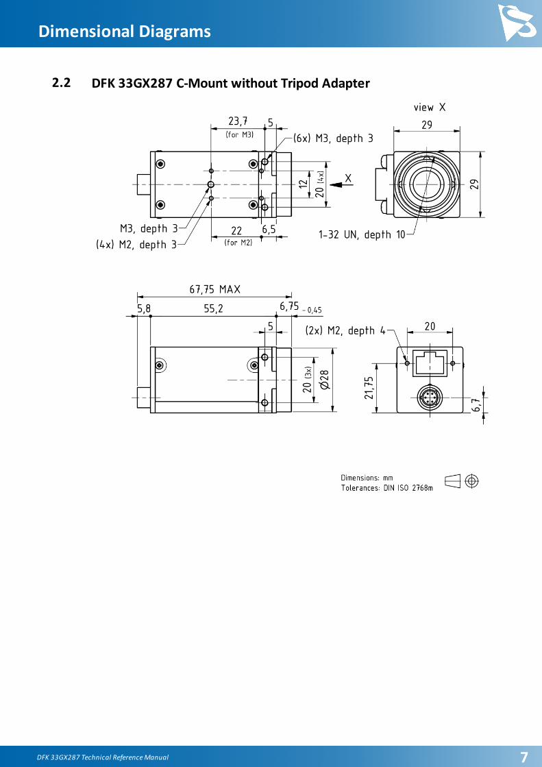
2.2 DFK 33GX287 C-Mount without Tripod Adapter

DFK 33GX287 Technical Reference Manual 8
Dimensional Diagrams
2.3 DFK 33GX287 CS-Mount with Tripod Adapter

DFK 33GX287 Technical Reference Manual 9
Dimensional Diagrams
2.4 DFK 33GX287 CS-Mount without Tripod Adapter

DFK 33GX287 Technical Reference Manual 10
I/O Connector
3 I/O Connector
3.1 6-pin I/O Connector
Rear view of camera
Pin Signal I/O Remarks Characteristics
Min Typ Max Unit
1 GigE Power
Supply
P3 11.0 12.0 13.0 V
2 TRIGGER_IN (+) I3 Optocoupler signal 3.32 - 24.02 V
3 TRIGGER_IN (-) I3 Optocoupler ground - - - -
4 STROBE_OUT O3 Open drain - - 24.01 V
5 GND_I/O G3 External Ground (Open
Drain)
- - - -
6 GND_DC G3 External Ground (Power
Supply)
- - - -
1 max. 0.2A (ID) for open drain MOSFET!
2 min. 3.5 mA driver strength required!
3 G: Ground O: Output I: Input
The part number of this Hirose connector is HR10A-7R-6P(73). To create an I/O cable
you need a Hirose connector HR10A-7P-6S(73).
3.1.1 TRIGGER_IN
The TRIGGER_IN line can be used to synchronize the start of the exposure time with
external events. The Trigger section describes in detail how the image sensor's behavior
can be controlled.

DFK 33GX287 Technical Reference Manual 11
I/O Connector
The current input signal can also be read directly through the General Purpose Input
feature.
3.1.2 STROBE_OUT
The STROBE_OUT line's main usage is to indicate the integration time of the image
sensor which allows flashes, strobes or other light sources to be synchronized with
camera operation. The line's behavior can be controlled through the Strobe controls.
The output signal can also be directly controlled through the General Purpose Output
feature.

DFK 33GX287 Technical Reference Manual 12
Spectral Characteristics
4 Spectral Characteristics
4.1 IR-Cut Filter
4.2 Spectral Sensitivity - IMX287LQR-C

DFK 33GX287 Technical Reference Manual 13
Camera Controls
5 Camera Controls
This section describes the parameters available for the DFK 33GX287 camera.
The actual name of the parameter depends on the driver technology used to access the
camera. Parameter names are listed for the most common ways to access the cameras:
· GigE Vision (cross platform, via 3rd party driver)
· IC Imaging Control (on Windows, via Device Driver for The Imaging Source GigE
Cameras)
5.1 Sensor Readout Control5.1.1 Pixel Format
The pixel format defines the data type of the pixels transmitted to the computer. The
bits per pixel needed for a particular pixel format influence the required bandwith.
The driver technology used to access the camera significantly impacts the way the pixel
format is controlled:
· When using GigE Vision, the pixel format is controlled through the PixelFormat
GenICam feature.
· When using IC Imaging Control, the pixel format is part of the video format - a
parameter which combines pixel format, resolution and readout mode. For more
information, refer to the IC Imaging Control documentation sections on
VideoFormat and VideoFormatDesc.
The DFK 33GX287 color camera supports multiple pixel formats with variable bits-per-
pixel settings. The names of the pixel formats and the way to select them depends on
the driver used to control the camera. The following table contains a short overview of
all possible formats followed by a more detailed description.
Pixel Format Bits Per Pixel GigE Vision TIS GigE Driver
8-Bit Bayer (RG) 8 BayerRG8 RGB32, Y800
12-Bit Packed Bayer
(RG)
12 BayerRG12p RGB64, Y16
16-Bit Bayer (RG) 16 BayerRG16 RGB64, Y16
5.1.1.1 8-Bit Bayer Raw
This format transmits data using one byte for each pixel.
GigE Vision drivers see this pixel format as one of the 8-bit bayer raw formats
(BayerGR8, BayerRG8, BayerGB8, BayerBG8).
The Device Driver for The Imaging Source GigE Cameras simplifies this variety of possible
pixel formats and offers two video formats instead: RGB32 and Y800. The RGB32
DFK 33GX287 Technical Reference Manual 14
Camera Controls
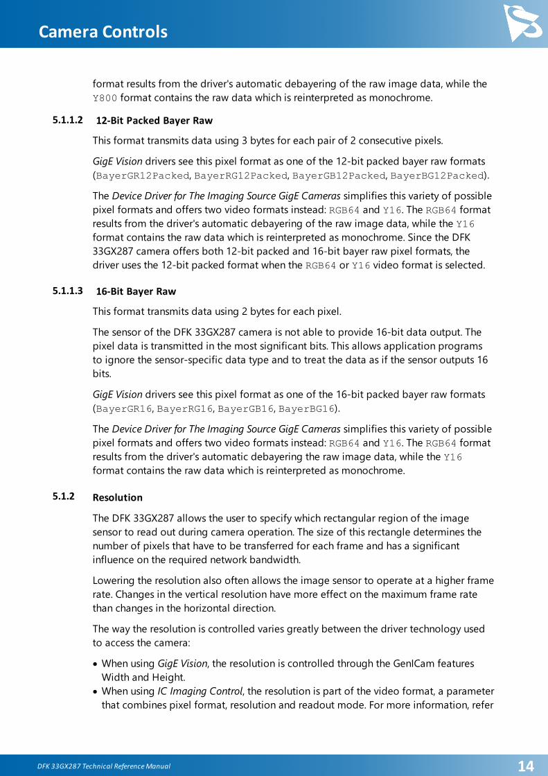
format results from the driver's automatic debayering of the raw image data, while the
Y800 format contains the raw data which is reinterpreted as monochrome.
5.1.1.2 12-Bit Packed Bayer Raw
This format transmits data using 3 bytes for each pair of 2 consecutive pixels.
GigE Vision drivers see this pixel format as one of the 12-bit packed bayer raw formats
(BayerGR12Packed, BayerRG12Packed, BayerGB12Packed, BayerBG12Packed).
The Device Driver for The Imaging Source GigE Cameras simplifies this variety of possible
pixel formats and offers two video formats instead: RGB64 and Y16. The RGB64 format
results from the driver's automatic debayering of the raw image data, while the Y16
format contains the raw data which is reinterpreted as monochrome. Since the DFK
33GX287 camera offers both 12-bit packed and 16-bit bayer raw pixel formats, the
driver uses the 12-bit packed format when the RGB64 or Y16 video format is selected.
5.1.1.3 16-Bit Bayer Raw
This format transmits data using 2 bytes for each pixel.
The sensor of the DFK 33GX287 camera is not able to provide 16-bit data output. The
pixel data is transmitted in the most significant bits. This allows application programs
to ignore the sensor-specific data type and to treat the data as if the sensor outputs 16
bits.
GigE Vision drivers see this pixel format as one of the 16-bit packed bayer raw formats
(BayerGR16, BayerRG16, BayerGB16, BayerBG16).
The Device Driver for The Imaging Source GigE Cameras simplifies this variety of possible
pixel formats and offers two video formats instead: RGB64 and Y16. The RGB64 format
results from the driver's automatic debayering the raw image data, while the Y16
format contains the raw data which is reinterpreted as monochrome.
5.1.2 Resolution
The DFK 33GX287 allows the user to specify which rectangular region of the image
sensor to read out during camera operation. The size of this rectangle determines the
number of pixels that have to be transferred for each frame and has a significant
influence on the required network bandwidth.
Lowering the resolution also often allows the image sensor to operate at a higher frame
rate. Changes in the vertical resolution have more effect on the maximum frame rate
than changes in the horizontal direction.
The way the resolution is controlled varies greatly between the driver technology used
to access the camera:
· When using GigE Vision, the resolution is controlled through the GenICam features
Width and Height.
· When using IC Imaging Control, the resolution is part of the video format, a parameter
that combines pixel format, resolution and readout mode. For more information, refer

DFK 33GX287 Technical Reference Manual 15
Camera Controls
to the IC Imaging Control documentation sections on VideoFormat and
VideoFormatDesc.
Parameter Horizontal Resolution
Minimum 256
Maximum 720
GigE Vision: GenICam Width
Parameter Vertical Resolution
Minimum 4
Maximum 540
GigE Vision: GenICam Height
5.1.3 Frame Rate
The frame rate is specified in frames per second and determines the camera's operating
speed.
The way the frame rate is controlled depends greatly upon which driver technology is
used to access the camera:
· When using GigEVision, the frame rate is controlled through the GenICam feature
AcquisitionFrameRate.
· When using IC Imaging Control, the frame rate is selected from a list of available
frame rates through APIs such as Grabber::setFPS or
ICImagingControl.DeviceFrameRate.
The range of available frame rates depends upon other camera settings such as well,
pixel format, resolution and readout modes.
Parameter Frame Rate
Minimum Depending on Pixel Format, Resolution, and Readout
Mode
Maximum Depending on Pixel Format, Resolution, and Readout
Mode
GigE Vision: GenICam AcquisitionFrameRate
The following tables show the maximum frame rate for some combinations of pixel
format and resolution.
8-Bit Bayer Raw

DFK 33GX287 Technical Reference Manual 16
Camera Controls
Width Height Maximum Frame Rate
720 540 300
640 480 379
12-Bit Packed Bayer Raw
Width Height Maximum Frame Rate
720 540 200
640 480 253
16-Bit Bayer Raw
Width Height Maximum Frame Rate
720 540 150
640 480 189
5.1.4 Partial Scan Offset
If the selected resolution is smaller than the sensor size, the part of the sensor that is
actually read out can be specified by the Partial Scan Offset X and Partial Scan Offset Y
parameters. By default, the camera automatically positions the offsets so that the center
of the sensor is used.
Parameter Partial Scan Offset X
Minimum 0
Maximum 464
GigE Vision: GenICam OffsetX
VCD Property VCDID_PartialScanOffset\VCDElement_PartialScanOffsetX
Parameter Partial Scan Offset Y
Minimum 0
Maximum 536
GigE Vision: GenICam OffsetY
VCD Property VCDID_PartialScanOffset\VCDElement_PartialScanOffsetY
DFK 33GX287 Technical Reference Manual 17
Camera Controls
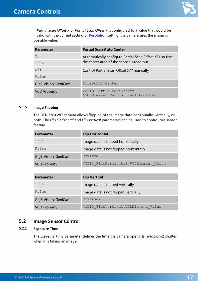
If Partial Scan Offset X or Partial Scan Offset Y is configured to a value that would be
invalid with the current setting of Resolution setting, the camera uses the maximum
possible value.
Parameter Partial Scan Auto Center
On Automatically configure Partial Scan Offset X/Y so that
the center area of the sensor is read outTrue
Off Control Partial Scan Offset X/Y manually
False
GigE Vision: GenICam OffsetAutoCenter
VCD Property VCDID_PartialScanOffset\VCDElement_PartialScanAutoCenter
5.1.5 Image Flipping
The DFK 33GX287 camera allows flipping of the image data horizontally, vertically, or
both. The Flip Horizontal and Flip Vertical parameters can be used to control this sensor
feature.
Parameter Flip Horizontal
True Image data is flipped horizontally
False Image data is not flipped horizontally
GigE Vision: GenICam ReverseX
VCD Property VCDID_FlipHorizontal\VCDElement_Value
Parameter Flip Vertical
True Image data is flipped vertically
False Image data is not flipped vertically
GigE Vision: GenICam ReverseY
VCD Property VCDID_FlipVertical\VCDElement_Value
5.2 Image Sensor Control5.2.1 Exposure Time
The Exposure Time parameter defines the time the camera opens its (electronic) shutter
when it is taking an image.

DFK 33GX287 Technical Reference Manual 18
Camera Controls
Parameter Exposure Time
Minimum 1 µs
Maximum 30 s
Default auto
GigE Vision: GenICam ExposureTime
VCD Property VCDID_Exposure\VCDElement_Value
5.2.2 Gain
The Gain parameter defines the amplification that is applied to the image at sensor
level.
Parameter Gain
Minimum 0 dB
Maximum 48 dB
Default auto
GigE Vision: GenICam Gain
VCD Property VCDID_Gain\VCDElement_Value
5.2.3 Black Level
The Black Level parameter defines the lowest possibly intensity value of the image
sensor.
Parameter Black Level
Minimum 0
Maximum 4095
Default 240
GigE Vision: GenICam BlackLevel
VCD Property VCDID_Brightness\VCDElement_Value
5.3 Automatic Exposure and Gain Control
The DFK 33GX287 camera can automatically control gain and exposure time. These
automatic functions are enabled by default.
In order to optimize image parameters, a region of interest can be specified for
automatic functions. Specifying a region of interest enables fine-grained control over

DFK 33GX287 Technical Reference Manual 19
Camera Controls
the image area for which the image parameters are optimized. A selection of pre-
defined area presets is available, but the user can also specify the coordinates of a
custom rectangle.
In certain situations, it is desirable to limit the range of the auto-controlled parameters.
For example, one might want to avoid high gain settings in order to keep noise levels
low. Other applications require limiting the maximum exposure time so that
movements do not get blurred. Therefore, the ranges of the gain and exposure
parameter can be limited.
If both auto exposure and auto gain are active, the camera tries to lower the gain value
in order to reduce noise and improve the image quality.
5.3.1 Auto Exposure
Parameter Auto Exposure
Continuous Enable Auto Exposure
True
Off Disable Auto Exposure
False
GigE Vision: GenICam ExposureAuto
VCD Property VCDID_Exposure\VCDElement_Auto
5.3.2 Auto Gain
Parameter Auto Gain
Continuous Enable Auto Gain
True
Off Disable Auto Gain
False
GigE Vision: GenICam GainAuto
VCD Property VCDID_Gain\VCDElement_Auto
5.3.3 Auto Reference Value
The Auto Reference Value parameter specifies the target brightness for both auto
exposure and auto gain.

DFK 33GX287 Technical Reference Manual 20
Camera Controls
Parameter Auto Reference Value
Minimum 0
Maximum 255
Default 128
GigE Vision: GenICam ExposureAutoReference
VCD Property VCDID_Exposure\VCDElement_AutoReference
5.3.4 Highlight Reduction
Enabling Highlight Reduction lets the auto exposure and auto gain functions reduce
overexposed areas in the output image. This feature is particularly useful when using
10/12/16-bit output images and a tone mapping algorithm in post-processing when
using higher bit depths as the dark areas still contain a lot of useful information.
Parameter Highlight Reduction
True Try to reduce overexposed areas
False Ignore overexposed areas and focus on matching the
image brightness to the selected Auto Reference Value.
GigE Vision: GenICam ExposureAutoHighlightReduction
VCD Property VCDID_HighlightReduction\VCDElement_Value
5.3.5 Auto Exposure Limits
The Auto Exposure Lower Limit parameter determines the minimum possible value that
can be set by the auto exposure algorithm.
Parameter Auto Exposure Lower Limit
Minimum 1 µs
Maximum 30 s
GigE Vision: GenICam ExposureAutoLowerLimit
The Auto Exposure Upper Limit parameter determines the maximum possible value that
can be set by the auto exposure algorithm.

DFK 33GX287 Technical Reference Manual 21
Camera Controls
Parameter Auto Exposure Upper Limit
Minimum 1 µs
Maximum 30 s
GigE Vision: GenICam ExposureAutoUpperLimit
VCD Property VCDID_Exposure\VCDElement_AutoMaxValue
If the Auto Exposure Upper Limit Auto parameter is enabled, the value of Auto Exposure
Upper Limit is automatically kept at the maximum possible value for the current frame
rate.
Parameter Auto Exposure Upper Limit Auto
On Select Auto Exposure Upper Limit automatically
Off Let the user control Auto Exposure Upper Limit
GigE Vision: GenICam ExposureAutoUpperLimitAuto
VCD Property VCDID_Exposure\VCDElement_AutoMaxValueAuto
5.3.6 Auto Gain Limits
The Auto Gain Lower Limit parameter determines the minimum possible value that can
be set by the auto gain algorithm.
Parameter Auto Gain Lower Limit
Minimum 0 dB
Maximum 48 dB
GigE Vision: GenICam GainAutoLowerLimit
The Auto Gain Upper Limit parameter determines the maximum possible value that can
be set by the auto gain algorithm.
Parameter Auto Gain Upper Limit
Minimum 0 dB
Maximum 48 dB
GigE Vision: GenICam GainAutoUpperLimit
5.4 Trigger
The trigger mode can be used to take images at very specific points in time which are
specified by an electrical signal connected to the TRIGGER_IN pin of the I/O connector

DFK 33GX287 Technical Reference Manual 22
Camera Controls
of the camera.
5.4.1 Trigger Mode
The Trigger Mode parameter enables the trigger mode.
Parameter Trigger Mode
On Enable Trigger Mode
True
Off Disable Trigger Mode
False
GigE Vision: GenICam TriggerMode
VCD Property VCDID_Trigger\VCDElement_Value
5.4.2 Trigger Polarity
The Trigger Polarity parameter controls whether a trigger event is accepted on the rising
or falling edge of the signal connected to the TRIGGER_IN line.
Parameter Trigger Polarity
RisingEdge Accept rising edge as trigger signal
True
FallingEdge Accept falling edge as trigger signal
False
GigE Vision: GenICam TriggerActivation
VCD Property VCDID_Trigger\VCDElement_Polarity
5.4.3 Software Trigger
The Software Trigger function can be used to simulate a trigger pulse, in turn causing
one image to be exposed and delivered to the host computer.
Parameter Software Trigger
Execute Simulate one trigger pulse
GigE Vision: GenICam TriggerSoftware
VCD Property VCDID_Trigger\VCDElement_SoftwareTrigger

DFK 33GX287 Technical Reference Manual 23
Camera Controls
5.4.4 Trigger Burst Count
The Trigger Burst Count parameter allows the camera to be configured to take more
than one image per trigger pulse. By default, this parameter is set to 1 so that exactly
one image is acquired. The images are taken as rapidly as possible given current
settings (i.e. as limited by the current exposure time and frame rate settings).
Parameter Trigger Burst Count
Minimum 1
Maximum 1000
Default 1
GigE Vision: GenICam AcquisitionBurstFrameCount
VCD Property VCDID_Trigger\VCDElement_TriggerBurstCount
5.4.5 Trigger Source
The Trigger Source parameter allows the camera to be configured to only accept trigger
signals from a specified source, e.g. only software trigger.
Parameter Trigger Source
Any Allow trigger signals from any source
Line1 Allow only hardware trigger
Software Allow only software trigger
GigE Vision: GenICam TriggerSource
5.4.6 Trigger Overlap
The Trigger Overlap feature gives information on when a new trigger pulse is accepted
in the trigger -> exposure -> readout sequence.
Parameter Trigger Overlap
Off The next trigger pulse is only accepted once the previous
frame has been read out from the sensor
Readout The next trigger pulse is accepted during readout as long
as the remaining readout time is shorter than the
exposure time
GigE Vision: GenICam TriggerOverlap
VCD Property VCDID_Trigger\VCDElement_TriggerOverlap

DFK 33GX287 Technical Reference Manual 24
Camera Controls
5.4.7 IMX Low-Latency Mode
The IMX Low-Latency Mode parameter controls whether the sensor operates in low-
latency trigger mode.
Parameter IMX Low-Latency Mode
True Delay between trigger input and start of exposure is
exactly as configured through the Trigger Delay feature
False Delay between trigger input and start of exposure is the
time configured by the Trigger Delay feature in addition
to a random delay depending on resolution, frame rate,
and timing relative to the sensor's internal state
GigE Vision: GenICam IMXLowLatencyMode
VCD Property VCDID_Trigger\VCDElement_IMXLowLatencyMode
Important: If IMX Low-Latency Mode is enabled, Trigger Overlap is not allowed and is
thereby forced to Off.
5.5 Trigger Timing Parameters
The 33G series camera series offers several options for dealing with bad trigger signals.
By using the Debounce Time, Denoise Time and Mask Time parameters, the camera can
be configured to ignore pulses on its TRIGGER_IN line under certain conditions.
Useful values for these parameters are application-specific. They depend on the
expected trigger frequency, the exposure time and assumptions about the input signal
quality.
The default values for all these parameters is 0 µs, assuming perfect signal quality.
5.5.1 Trigger Delay
The Trigger Delay parameter specifies a time for which the camera waits between
receiving a trigger signal and starting the exposure of an image. Simulated trigger
pulses generated through the Software Trigger function are not delayed by this
parameter.

DFK 33GX287 Technical Reference Manual 25
Camera Controls
Parameter Trigger Delay
Minimum 0 s
Maximum 1 s
Default 0 s
GigE Vision: GenICam TriggerDelay
VCD Property VCDID_Trigger\VCDElement_TriggerDelay
5.5.2 Trigger Debounce Time
The Trigger Debounce Time parameter specifies the time for which the trigger input has
to be low in order for the next trigger signal to be accepted.
Parameter Trigger Debounce Time
Minimum 0 s
Maximum 1 s
Default 0 s
GigE Vision: GenICam TriggerDebouncer
VCD Property VCDID_Trigger\VCDElement_TriggerDebouncer
5.5.3 Trigger Mask Time
The Trigger Mask Time parameter specifies the time for which trigger pulses are ignored
after accepting a trigger signal.
Parameter Trigger Mask Time
Minimum 0 s
Maximum 1 s
Default 0 s
GigE Vision: GenICam TriggerMask
VCD Property VCDID_Trigger\VCDElement_TriggerMask
5.5.4 Trigger Noise Suppression Time
The Trigger Noise Suppression Time parameter specifies the time for which trigger input
has to be active in order to be accepted as a trigger signal.

DFK 33GX287 Technical Reference Manual 26
Camera Controls
Parameter Trigger Noise Suppression Time
Minimum 0 s
Maximum 1 s
Default 0 s
GigE Vision: GenICam TriggerDenoise
VCD Property VCDID_Trigger\VCDElement_TriggerDenoise
5.6 Digital I/O
The 33G series has one digital input and one digital output. The digital input can be
used as a Trigger input but the current status can also examined directly.
The digital output can be configured as a Strobe output to signal the exact moment
when the image sensor is sensitive to light so that external light sources can be
synchronized to its operation cycle.
5.6.1 General Purpose Input
The General Purpose Input parameter allows the current status of the TRIGGER_IN pin.
Parameter General Purpose Input
True TRIGGER_IN line status is low
1
False TRIGGER_IN line status is high
0
GigE Vision: GenICam GPIn
VCD Property VCDID_GPIO\VCDElement_GPIOReadVCDID_GPIO\VCDElement_GPIOIn
5.6.2 General Purpose Output
The General Purpose Output parameter controls the status of the STROBE_OUT pin.

DFK 33GX287 Technical Reference Manual 27
Camera Controls
Parameter General Purpose Output
True Drive the STROBE_OUT line high
1
False Drive the STROBE_OUT line low
0
GigE Vision: GenICam GPOut
VCD Property VCDID_GPIO\VCDElement_GPIOWriteVCDID_GPIO\VCDElement_GPIOOut
5.7 Strobe
The strobe function controls the automatic generation of output pulses on the
STROBE_OUT pin which is synchronized to the image sensor's exposure time.
5.7.1 Strobe Enable
The Strobe Enable parameter enables the automatic generation of strobe pulses.
Parameter Strobe Enable
On Strobe enabled
True
Off Strobe disabled
False
GigE Vision: GenICam StrobeEnable
VCD Property VCDID_Strobe\VCDElement_Value
5.7.2 Strobe Polarity
The Strobe Polarity parameter can be used to invert the strobe pulse output.
Parameter Strobe Polarity
ActiveHigh The STROBE_OUT pin is logically high during the
exposure timeTrue
ActiveLow The STROBE_OUT pin is logically low during the
exposure timeFalse
GigE Vision: GenICam StrobePolarity
VCD Property VCDID_Strobe\VCDElement_StrobePolarity
DFK 33GX287 Technical Reference Manual 28
Camera Controls
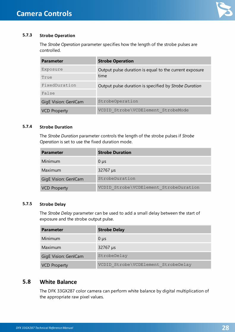
5.7.3 Strobe Operation
The Strobe Operation parameter specifies how the length of the strobe pulses are
controlled.
Parameter Strobe Operation
Exposure Output pulse duration is equal to the current exposure
timeTrue
FixedDuration Output pulse duration is specified by Strobe Duration
False
GigE Vision: GenICam StrobeOperation
VCD Property VCDID_Strobe\VCDElement_StrobeMode
5.7.4 Strobe Duration
The Strobe Duration parameter controls the length of the strobe pulses if Strobe
Operation is set to use the fixed duration mode.
Parameter Strobe Duration
Minimum 0 µs
Maximum 32767 µs
GigE Vision: GenICam StrobeDuration
VCD Property VCDID_Strobe\VCDElement_StrobeDuration
5.7.5 Strobe Delay
The Strobe Delay parameter can be used to add a small delay between the start of
exposure and the strobe output pulse.
Parameter Strobe Delay
Minimum 0 µs
Maximum 32767 µs
GigE Vision: GenICam StrobeDelay
VCD Property VCDID_Strobe\VCDElement_StrobeDelay
5.8 White Balance
The DFK 33GX287 color camera can perform white balance by digital multiplication of
the appropriate raw pixel values.

DFK 33GX287 Technical Reference Manual 29
Camera Controls
5.8.1 Auto White Balance
DFK 33GX287 can perform Auto White Balance. It can be enabled continuously when
changes in lighting conditions are expected. Under controlled lighting conditions,
however, one-time white balance calibration is the recommended approach.
To perform one-time white balance calibration, place a reference white sheet in front of
the camera and set BalanceWhiteAuto to Once. The camera will then find the correct
white balance settings for the current light conditions and keep them active until
instructed otherwise.
Parameter Auto White Balance
Continuous Enable automatic white balance
True
Once Enable automatic white balance until the color channels
have been balanced onceOne Push
Off Disable automatic white balance
False
GigE Vision: GenICam BalanceWhiteAuto
VCD Property VCDID_WhiteBalance\VCDElement_AutoVCDID_WhiteBalance\VCDElement_OnePush
5.8.2 White Balance Mode
The default auto white balance algorithm is Gray World. It is selected by setting the
White Balance Mode accordingly. The Gray World algorithm operates under the
assumption that the average color of a scene is near gray and adjusts the white balance
coefficients so the average color of the resulting image is gray as well. In the case
where this assumption is wrong (e.g. the camera is pointing at a blue carpet), the auto
white balance algorithm will select coefficients that do not result in a visually accurate
image.
To avoid the problems posed by the Gray World algorithm, the Temperature mode can
be used. This mode operates by trying to determine the color temperature of the light
source.
Parameter White Balance Mode
Gray World Use the Gray World model
Temperature Use the Temperature model
GigE Vision: GenICam BalanceWhiteMode
VCD Property VCDID_WhiteBalance\VCDElement_WhiteBalanceMode

DFK 33GX287 Technical Reference Manual 30
Camera Controls
To assist the automatic white balance temperature detection, White Balance Auto Preset
can be used to limit the range of valid color temperatures.
Parameter White Balance Auto Preset
Any Allow any color temperature
Auto Warm White Limit color temperature to approximately 2500-4000 K
Auto Cool White Limit color temperature to approximately 4000-5800 K
Auto Daylight Limit color temperature to approximately 5700-7500 K
Auto Deep Shade Limit color temperature to approximately 7500-10000 K
GigE Vision: GenICam BalanceWhiteAutoPreset
VCD Property VCDID_WhiteBalance\VCDElement_WhiteBalanceAutoPreset
5.8.3 Manual White Balance
If Auto White Balance is not enabled, the amplifiers for the red, green and blue channels
can be controlled manually.
Parameter White Balance Red
Minimum 0
Maximum 3.984375
Default auto
GigE Vision: GenICam BalanceRatio[BalanceRatioSelector=Red]
VCD Property VCDID_WhiteBalance\VCDElement_WhiteBalanceRed
Parameter White Balance Green
Minimum 0
Maximum 3.984375
Default auto
GigE Vision: GenICam BalanceRatio[BalanceRatioSelector=Green]
VCD Property VCDID_WhiteBalance\VCDElement_WhiteBalanceGreen

DFK 33GX287 Technical Reference Manual 31
Camera Controls
Parameter White Balance Blue
Minimum 0
Maximum 3.984375
Default auto
GigE Vision: GenICam BalanceRatio[BalanceRatioSelector=Blue]
VCD Property VCDID_WhiteBalance\VCDElement_WhiteBalanceBlue
If White Balance Mode is set to Temperature, the color temperature can be set directly.
Additionally, a light source can be selected from a list of presets.
Parameter White Balance Temperature
Minimum 2500 K
Maximum 10000 K
Default auto
GigE Vision: GenICam BalanceWhiteTemperature
VCD Property VCDID_WhiteBalance\VCDElement_WhiteBalanceTemperature
Parameter White Balance Temperature Preset
Sodium-Vapor Lamp 2500 K
Warm Light 2700 K
Halogen Light 3000 K
Neutral White 3500 K
Cool WhiteFluorescent Light
4000 K
Cool White/Daylight(CFL)
5000 K
Daylight 6000 K
Cool White LED 7500 K
Blue Sky 10000 K
GigE Vision: GenICam BalanceWhiteTemperaturePreset
VCD Property VCDID_WhiteBalance\VCDElement_TemperaturePreset
DFK 33GX287 Technical Reference Manual 32
Camera Controls
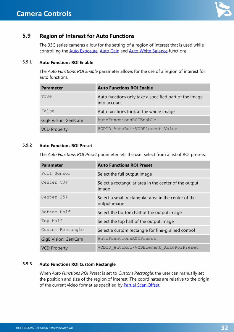
5.9 Region of Interest for Auto Functions
The 33G series cameras allow for the setting of a region of interest that is used while
controlling the Auto Exposure, Auto Gain and Auto White Balance functions.
5.9.1 Auto Functions ROI Enable
The Auto Functions ROI Enable parameter allows for the use of a region of interest for
auto functions.
Parameter Auto Functions ROI Enable
True Auto functions only take a specified part of the image
into account
False Auto functions look at the whole image
GigE Vision: GenICam AutoFunctionsROIEnable
VCD Property VCDID_AutoRoi\VCDElement_Value
5.9.2 Auto Functions ROI Preset
The Auto Functions ROI Preset parameter lets the user select from a list of ROI presets.
Parameter Auto Functions ROI Preset
Full Sensor Select the full output image
Center 50% Select a rectangular area in the center of the output
image
Center 25% Select a small rectangular area in the center of the
output image
Bottom Half Select the bottom half of the output image
Top Half Select the top half of the output image
Custom Rectangle Select a custom rectangle for fine-grained control
GigE Vision: GenICam AutoFunctionsROIPreset
VCD Property VCDID_AutoRoi\VCDElement_AutoRoiPreset
5.9.3 Auto Functions ROI Custom Rectangle
When Auto Functions ROI Preset is set to Custom Rectangle, the user can manually set
the position and size of the region of interest. The coordinates are relative to the origin
of the current video format as specified by Partial Scan Offset.

DFK 33GX287 Technical Reference Manual 33
Camera Controls
Parameter Auto Functions ROI Left
Minimum 0
Maximum 704
GigE Vision: GenICam AutoFunctionsROILeft
VCD Property VCDID_AutoRoi\VCDElement_AutoRoiLeftRelative
Parameter Auto Functions ROI Top
Minimum 0
Maximum 524
GigE Vision: GenICam AutoFunctionsROITop
VCD Property VCDID_AutoRoi\VCDElement_AutoRoiTopRelative
Parameter Auto Functions ROI Width
Minimum 16
Maximum 720
GigE Vision: GenICam AutoFunctionsROIWidth
VCD Property VCDID_AutoRoi\VCDElement_AutoRoiWidthRelative
Parameter Auto Functions ROI Height
Minimum 16
Maximum 540
GigE Vision: GenICam AutoFunctionsROIHeight
VCD Property VCDID_AutoRoi\VCDElement_AutoRoiHeightRelative
5.10 User Sets
The 33G series cameras can store their complete configuration into built-in non-volatile
memory. The camera configuration can be saved into and restored from one of two
available memory slots upon user's request. Additionally, the camera can be configured
to load one of the user's camera configurations at startup.
DFK 33GX287 Technical Reference Manual 34
Camera Controls
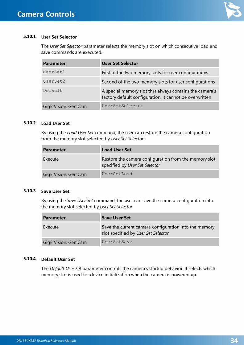
5.10.1 User Set Selector
The User Set Selector parameter selects the memory slot on which consecutive load and
save commands are executed.
Parameter User Set Selector
UserSet1 First of the two memory slots for user configurations
UserSet2 Second of the two memory slots for user configurations
Default A special memory slot that always contains the camera's
factory default configuration. It cannot be overwritten
GigE Vision: GenICam UserSetSelector
5.10.2 Load User Set
By using the Load User Set command, the user can restore the camera configuration
from the memory slot selected by User Set Selector.
Parameter Load User Set
Execute Restore the camera configuration from the memory slot
specified by User Set Selector
GigE Vision: GenICam UserSetLoad
5.10.3 Save User Set
By using the Save User Set command, the user can save the camera configuration into
the memory slot selected by User Set Selector.
Parameter Save User Set
Execute Save the current camera configuration into the memory
slot specified by User Set Selector
GigE Vision: GenICam UserSetSave
5.10.4 Default User Set
The Default User Set parameter controls the camera's startup behavior. It selects which
memory slot is used for device initialization when the camera is powered up.

DFK 33GX287 Technical Reference Manual 35
Camera Controls
Parameter Default User Set
UserSet1 Load configuration from the first memory slot
UserSet2 Load configuration from the second memory slot
Default Load factory default configuration
GigE Vision: GenICam UserSetDefault
5.11 Multi-Frame Output Mode
The 33G series cameras support cycling the exposure time through pre-programmed
values from frame to frame in order to form a frame set. In post-processing, sets of
frames captured with different exposure times can be used to create images with higher
dynamic range than those from single exposure.
The camera can be configured to use 2 or 4 different exposure times.
If required, different gain values can be selected for use along with the configured
exposure times.
5.11.1 Multi-Frame Output Mode Enable
The Multi-Frame Output Mode Enable parameter activates the multi-frame output mode.
Parameter Multi-Frame Output Mode Enable
True Cycle through the exposure times specified by Multi-
Frame Output Mode Exposure Time
False Use the exposure time defined by Exposure Time for all
frames
GigE Vision: GenICam MultiFrameSetOutputModeEnable
VCD Property VCDID_MultiFrameOutputMode\VCDElement_Value
5.11.2 Multi-Frame Output Mode Frame Count
The Multi-Frame Output Mode Frame Count parameter defines the number of frames in
a frame set.
Parameter Multi-Frame Output Mode Frame Count
2 Frames Use two different exposure times
4 Frames Use four different exposure times
GigE Vision: GenICam MultiFrameSetOutputModeFrameCount
VCD Property VCDID_MultiFrameOutputMode\VCDElement_MultiFrameCount

DFK 33GX287 Technical Reference Manual 36
Camera Controls
5.11.3 Multi-Frame Output Mode Exposure Time
The Multi-Frame Output Mode Exposure Time parameters control the different exposure
times in a frame set.
Parameter Multi-Frame Output Mode Exposure Time
Minimum 20 µs
Maximum 30000000 µs
GigE Vision: GenICam MultiFrameSetOutputModeExposureTime0
MultiFrameSetOutputModeExposureTime1
MultiFrameSetOutputModeExposureTime2MultiFrameSetOutputModeExposureTime3
VCD Property VCDID_MultiFrameOutputMode
\VCDElement_MultiFrameExposure0
\VCDElement_MultiFrameExposure1
\VCDElement_MultiFrameExposure2\VCDElement_MultiFrameExposure3
5.11.4 Multi-Frame Output Mode Custom Gain
The Multi-Frame Output Mode Custom Gain parameter allows specifying different gain
values for each frame in a frame set.
Parameter Multi-Frame Output Mode Custom Gain
True Cycle through the gain values specified by Multi-Frame
Output Mode Gain
False Use the gain value defined by Gain
GigE Vision: GenICam MultiFrameSetOutputModeCustomGain
VCD Property VCDID_MultiFrameOutputMode\VCDElement_MultiFrameCustomGainEnable
5.11.5 Multi-Frame Output Mode Gain
The Multi-Frame Output Mode Gain parameters controls the gain values used to capture
the images of the frame set.

DFK 33GX287 Technical Reference Manual 37
Camera Controls
Parameter Multi-Frame Output Mode Gain
Minimum 0 dB
Maximum 48 dB
GigE Vision: GenICam MultiFrameSetOutputModeGain0
MultiFrameSetOutputModeGain1
MultiFrameSetOutputModeGain2MultiFrameSetOutputModeGain3
VCD Property VCDID_MultiFrameOutputMode
\VCDElement_MultiFrameGain0
\VCDElement_MultiFrameGain1
\VCDElement_MultiFrameGain2\VCDElement_MultiFrameGain3

DFK 33GX287 Technical Reference Manual 38
Revision History
6 Revision History
Date Version Description
2018/06/28 Initial release of this document

DFK 33GX287 Technical Reference Manual 39
DFK 33GX287 Technical Reference Manual
Al l product and company names in this document may be trademarks and tradenames of their respectiveowners and are hereby acknowledged.
The Imaging Source Europe GmbH cannot and does not take any respons ibi l i ty or l iabi l i ty for any informationconta ined in this document. The source code presented in this document i s exclus ively used for didacticpurposes . The Imaging Source does not assume any kind of warranty expressed or impl ied, resul ting from theuse of the content of this document or the source code.
The Imaging Source Company reserves the right to make changes in speci fications , function or des ign at anytime and without prior notice.
Last update: June 2018© 2018 The Imaging SourceAl l rights reserved. Reprint, a lso in parts , only a l lowed with permiss ion of The Imaging Source Europe GmbH.
Al l weights and dimens ions are approximate. Unless otherwise speci fied, the lenses shown in the context ofcameras are not shipped with these cameras .
Headquarters:
The Imaging Source Europe GmbHÜberseetor 18, D-28217 Bremen, GermanyPhone: +49 421 33591-0
North & South America:
The Imaging Source, LLC6926 Shannon Willow Rd, S 400, Charlotte, NC 28226, USAPhone: +1 704-370-0110
Asia Pacific:
The Imaging Source Asia Co., Ltd. 2F., No.8, Xinhu 1st Road Taipei City 114, Neihu District, TaiwanPhone: +886 2-2792-3153
www.theimagingsource.com