DFH Series Fume Hood2.2.1 DFH-7 Fume Hood Structure ... debugging methods, please refer to the...
22
DFH Series Fume Hood User Manual PLEASE READ THIS MANUAL CAREFULLY BEFORE OPERATION 3, Hagavish st. Israel 58817 Tel: 972 3 5595252, Fax: 972 3 5594529 [email protected] MRC. 8.19
Transcript of DFH Series Fume Hood2.2.1 DFH-7 Fume Hood Structure ... debugging methods, please refer to the...

DFH Series Fume Hood
User Manual
PLEASE READ THIS MANUAL CAREFULLY BEFORE OPERATION
3, Hagavish st. Israel 58817 Tel: 972 3 5595252, Fax: 972 3 5594529 [email protected]
MRC. 8.19

MRC Ltd
2
Preface
Thank you very much for purchasing our DFH series Fume Hood.
Please read the “Operating Instructions” and “Warranty” before operating this unit to assure proper operation. After reading these documents, be sure to store them securely together with the “Warranty” within touch for future reference.
Warning: Before operating the unit, be sure to read carefully and fully understand important warnings in the operating instructions.
Disclaimer MRC shall not be liable for any equipment failure or damage, or for any direct or indirect damage that may occur during the use of the equipment. 1.Malfunction or damage due to violation of the instructions, precautions, and intended useof this manual. 2.Malfunction or damage caused by repair or alteration of the other company.3.Malfunction or damage caused by use instruments of other company at the same time .4.Malfunction or damage caused by operating environment not corresponding to thespecified operating environment (power conditions, installation environment, etc). 5.Malfunction or damage caused by natural disasters such as earthquakes and floods.6.Malfunction or damage caused by the company unaware of the movement or transfer(transport) after installation.

MRC Ltd
3
Conten t
1. Unpacking, Installation & Debugging ............................................................................................................. 41.1Unpacking of Cabinet ................................................................................................................................... 4 1.2 Accessories Checking .................................................................................................................................. 6 1.3 Machine Installation Site & Use Environment ............................................................................................ 6 1.4 Installation ................................................................................................................................................... 6 1.5 Post-installation Checking ........................................................................................................................... 8
2. Instructions for Use ......................................................................................................................................... 92.1 Function ......................................................................................................................................................... 9
2.1.1 Product Concept ....................................................................................................................................... 9 2.1.2Working Principle / Airflow Mode Protection Area Diagram ................................................................... 9 2.1.3 Objects Protected ...................................................................................................................................... 9 2.1.4 Technical Parameters & Performance Indicators ................................................................................... 10
2.2Product Structure .................................................................................................................................. .........11 2.2.1 DFH-7 Fume Hood Structure .................................................................................................................. 11 2.2.2Structure Description ............................................................................................................................... 12
2.3 Points that Should Be Noted in Normal Operation & Normal Operation Process ...................................... 14 2.3.1Points that Should Be Noted in Normal Operation ................................................................................. 14 2.3.2Normal Operation Process ....................................................................................................................... 14
2.4 Daily Maintenance ...................................................................................................................................... 16 2.5 Accessories Replacement List ..................................................................................................................... 17 2.6Wiring Diagram ............................................................................................................................................ 18 3. Common Fault Analysis & Solution .............................................................................................................. 193.1 Common Fault Analysis .............................................................................................................................. 19 3.2 Label Description ........................................................................................................................................ 21 4.Warranty ......................................................................................................................................................... 21

MRC Ltd
4
1. Unpacking, Installation & DebuggingPlease check whether the packing box is intact, if not, please take photos.
1.1 Unpacking of Cabinet
(The user can choose the proper unpacking method according to the actual situation.)
box 1Method 1: Unpack with a wrench M8
Figure1 box 1Method 2: Unpack with an electric drill M8 sleeve

MRC Ltd
5
Figure 2
Rapid unpacking diagram (Disassemble the screws, as are shown in the below figure, then
take the wooden box to the left and right.)
Figure3 box2 Rapid unpacking Cut the packing belt off with an ordinary scissor, remove the top cover of the paper packing,

MRC Ltd
6
and move the paper packing frame upward.
Figure 4
1.2 Accessories Checking
Please refer to the packing list, carefully check whether the accessories and information are complete.
Hume Hood Packing List Upper cabinet:
No. Name Quantity 1 Cabinet 1 unit 2 User manual 1 copy 3 Certificate 1 sheet 4 Test report 1copy 5 Fuse (5A) 1pc 6 Power Cord 1pc 7 Exhaust pipe 1pc 8 Pipe clamp 1pc 9 Base (base connector) (optional) 1 set
1.3 Machine Installation Site and Use Environment
Installation site
Installation site of fume hood should be avoided to face road and sites people
frequently go through, avoided to clog windows and places where ventilation and lighting

MRC Ltd
7
are not good, avoided to block the entrance and exit and place where the open or close of the
door is affected , and avoided to place oppositely or in the corner of the wall.
Use environment:
a、 For indoor use only;
b、Environment temperature: 15℃~35℃;
c、 Relative humidity: ≤75%;
d、Atmospheric pressure range:70 kPa~106 kPa;
e、 Power: the same with the rated voltage, rated frequency of the cabinet, as is shown in the
2.1.4 Technical Parameters Performance Indicators Table
f、 Power supply needs reliable grounding; (judgment method: Use a multimeter to test the
voltage of the live line to ground and the voltage of the null line to ground respectively,
among which, the voltage of the live line to ground should be the grid power, and the
voltage of the null line to ground should be 0, otherwise, the power is not grounded
well).
1.4 Installation
a、 Remove all packaging components
b、 Check whether the outer surface of the cabinet has scratches, deformations or foreign
objects;
c、 Check carefully the accessories and information by referring to the packing list in the
user manual;
d、 Move the entire equipment to a site which is as close as possible to the position where
the equipment is placed finally and convenient for installation;
e、 Put the cabinet on the side platform of the lab.
f、 Check whether the ambient voltage frequency is consistent with the voltage frequency
shown on the label, then power on;

MRC Ltd
8
Figure 5
g、 Method for installation of base(optional) is as follows:
(1)Take a base rectangular pipe, and place it as is shown in the figure, then take 10
stainless steel hexagon socket bolts (M10),10 stainless steel spring washers 10, 10 stainless
steel flat washers 10, to assemble the base;
(2)Place the fume hood above the base, take 4 stainless steel hexagon screws (M6 *
35), 4 stainless steel spring washers 6, 4 stainless steel flat washers 6, and pass through the
base from the bottom of the base, then connect the base with the fume hood.

MRC Ltd
9
Figure 6
1.5 Post-installation Checking
1.Refer to 2.3.2 Normal Operation Process and check the following items, after the fumehood is powered on.
Checking Items Normal Status
Power status The equipment could be powered on/off after pressing the power button;
Fan Runs normally after pressing the Fan
button; speed could be adjusted by pressing the adjusting button;
Front acrylic door switch The status is normal; Fluorescent lamp Lamp lights up after pressing button.
If the equipment has problems, please contact the local dealer for debugging, for the
debugging methods, please refer to the after-sales service manual
2. Instruction for Use2.1 Function
2.1.1 Product Concept In the chemical laboratory, the experimental operation will produce a variety of harmful
odor gases, bad smell, moisture and corrosive substances, in order to protect the safety of
users and prevent contaminants in the experiment from spreading to the laboratory, the fume
stainless steel hexagon socket bolts
(M10), stainless steel spring washers
10, stainless steel flat washers 10
MRC Ltd
10
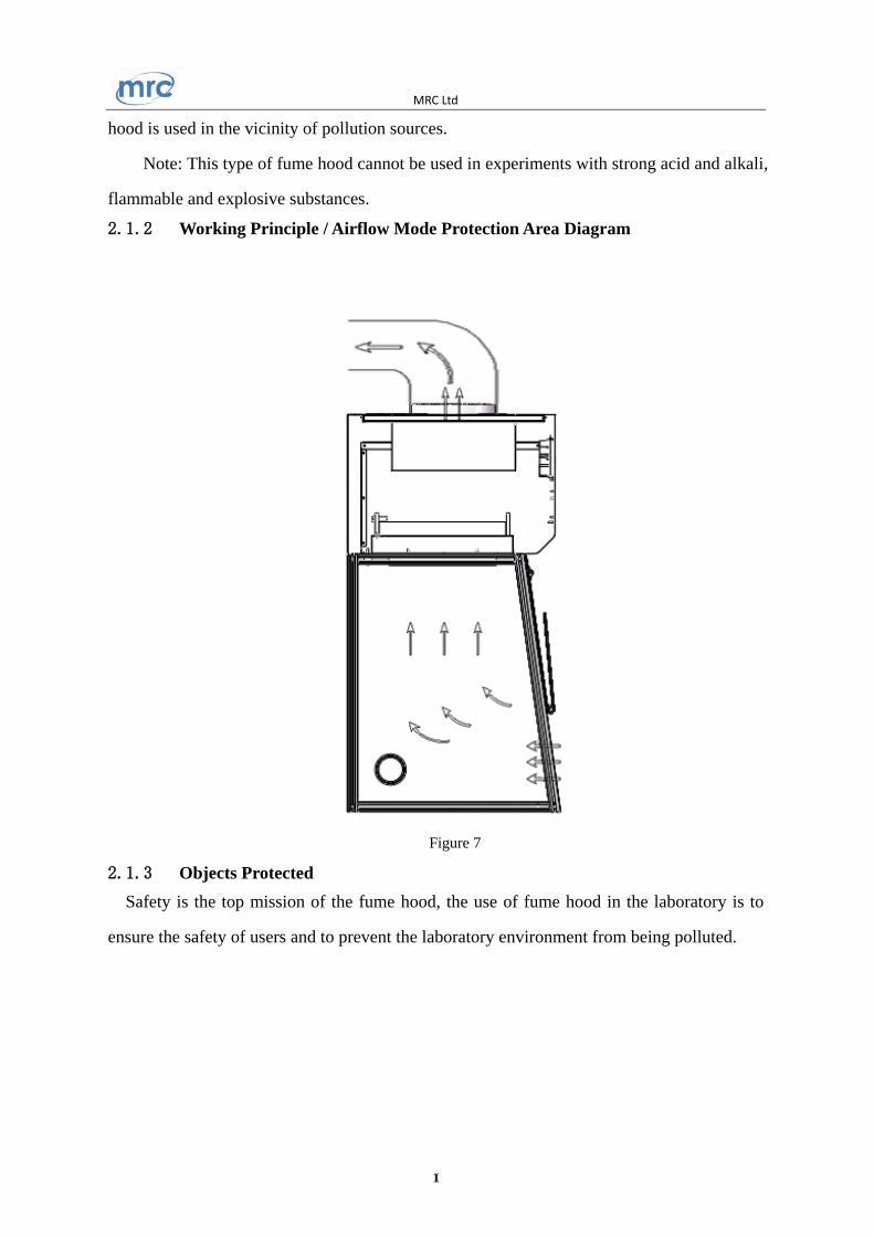
hood is used in the vicinity of pollution sources.
Note: This type of fume hood cannot be used in experiments with strong acid and alkali,
flammable and explosive substances.
2.1.2 Working Principle / Airflow Mode Protection Area Diagram
Figure 7
2.1.3 Objects Protected Safety is the top mission of the fume hood, the use of fume hood in the laboratory is to
ensure the safety of users and to prevent the laboratory environment from being polluted.

MRC Ltd
11
2.1.4 Technical Parameters & Performance Indicators
Model Technical Parameters
DFH-7
Rated voltage AC 220V±10% □ 110V±10% □
Rated frequency 50 Hz □ 60Hz □ External
dimension 700*620*1150 mm
Operating area dimension 640*550*700 mm
Rated power 300 W
Inflow velocity 0.3~0.8m/s Fluorescent lamp power T5 4W *2
Noise ≤70dB(A)
Note: (1) MRC reserves the right to change the design, if the product design is changed,
MRC shall no longer inform the user.
1)Vibration amplitude:
The net vibration amplitude between 10Hz and 10kHz frequency is ≤ 5 µm (rms)
2)Withstand voltage: If the voltages rises within 5s to 1390V AC voltage, the fume hood
could not break down within 5 seconds;
3)Grounding resistance: ≤ 0.1Ω;

MRC Ltd
12
2.2 Product Structure
2.2.1 FH 700 Fume Hood Structure
Figure 8
1.Deck panel 2. Front window (lower part)
3. Torque hinge 4. Front window (middle
part)
5 .Control panel 6. Power socket
7.Rubber plug
2.2.2 Structure Description
★Lighting source
LED lamp is used for lighting, to ensure the average illumination in the operating area
meets the standard requirements.
★Control panel
The control panel of the equipment has power button, fluorescent lamp button, fan
speed-adjustment button, UV lamp button, 5 touching buttons, as well as wind speed gear
display unit, indicator for each function.
1
2
3
4
5
6
7

MRC Ltd
13
F igure 9
Lightly press the button
The key to human-computer interaction is that the main operation of the equipment can
be done by touching the buttons. By touching buttons, the equipment can achieve the most
basic functions;
Power button: the main switch to control the other function buttons, as is shown
in No.1 of Figure 9.
the control button of the working state of the fan, as is shown in No.5 of Figure 9. Each touching can change the working state and the corresponding display state once.
Fan speed-adjustment button, , control button of fan wind speed, as is shown in
No.3 of Figure 9. Each touching can change the working state and the corresponding display
state in the wind speed gear display unit once. There are 9 gears to adjust, namely, from F1
to F9, when it is in F9, one more touching will be F1.
Each time, when the fan gear is adjusted, the current value will be memorized, that's to
say, each time, when the fan is powered on, the gear is the same with that when the fan was
powered off last time.
Fluorescent lamp button: , control button of the fluorescent lamp, as is shown in
No.2 of Figure 9. Each touching can change the working state of the lamp and the
2
4
5 3
1 6

MRC Ltd
14
corresponding display state of the indicator once, namely from lightening to darkness, or
from darkness to lightening.
UV lamp button: UV, control button of UV lamp (optional), as is shown in No.6 of
Figure 9. UV lamp interlocks with fan, fluorescent lamp, that's to say, when the fan or the
fluorescent lamp is powered on, the UV lamp will automatically power off.
★Fuse
The installation site of fuse is in the rear of the cabinet's top, as is shown in (Figure
8),the power socket of FH 700 fume hood is equipped with live line fuse, the specification
of which is consistent with the content of the label pasted on the bottom, and the
replacement should refer to the label content.
★Structure
a)External case body adopts 1.0 mm cold-rolled steel with electrostatic coating and
rust-proof treatment.
b)The desk panel adopts solid chemical resistant laminate, which can be disassembled, and
the cleaning is convenient.
c)The left, right, rear windows adopt 5mm thick tempered glass, and the front window
adopts acrylic, which can be stopped at any time.
d)Control panel adopts touch switch, making the appearance of the equipment beautiful,
besides it is easy to operate.
e) Electronic control system is equipped with anti-overload, anti-electric shock and other
functions, making the performance stable, and lifespan
2.3 Points that Should Be Noted in Normal Operation & Normal
Operation Process
2.3.1 Points that Should Be Noted in Normal Operation
Precautions
Fume hood is the important laboratory safety equipment, please read this manual and
precautions, as well as participate in laboratory safety and skills training to ensure normal

MRC Ltd
15
and safe use.
2、Please read this manual before using the fume hood.
3、Please keep this manual for further reference.
4、Any damage caused by the inappropriate use or product structure change. Our
company is out of responsibility.
5、The fume hood should avoid putting on the corridor or near the door or window with a
frequent personnel floating.
6、The power socket is grounded well.
7、The equipment should be powered off and unplugged before doing any replacement of
parts, such as UV lamp and fluorescent lamp.
8、The packed fume hood should be stored in a warehouse with relative humidity no more
than 75% and temperature lower than 40℃. The warehouse should have good ventilation
performance without acid, alkali or other corrosive gases.
9.The front window is made of acrylic, and the perspective window is made of explosion -
proof tempered glass. In order to keep the perspective window clean and clear, please wipe
it by wet soft cloth and keep it away from HF acid, etc.
10、The air deflector and other internal accessories should be cleaned according to the use of
the fume hood.
11、The air duct and the blower of the Fume Hood should be cleaned and maintained
regularly in a proper way
12、Do not put any equipment in a range within 150mm away from the glass window, large
experimental equipment needs to have sufficient space, the flow of air should not be
affected.
13、Do NOT place any soft or tiny materials (such as soft tissue) on the work table during
the operation to prevent breakdown of the blower causing by sucking those materials
14、The picture and design of the product of our company are subject to the material object,
if there are changes in the product model, we shall no longer inform the user.
NOTE: MRC WILL NOT BE LIABLE FOR ANY RISK OR DAMAGE ARISING
FROM YOUR FAILURE TO APPROPRIATELY OPERATION THE FUME HOOD!

MRC Ltd
16
2.3.2 Normal Operation Process
a、 Power on the fume hood by pressing the power switch, the LED screen would be lighted and
“---”would be shown.
b、Press the POWER button on the control panel, the LED screen would display the accumulated
operating time of the fan( that is the working time of the filter, the displayed value multiply by 10 is the
actual time, unit: hour), press the button, the screen will display the gear of the fan worked for last
time, the fan indicator
above the fan button will be lightened, and the operation can be done after working for 5 minutes.
c、Press the , the lighting indicator above the button will be lightened, one more pressing will turn
off the lamp (according to the laboratory environment, select to power on or off the lamp)
d、After using, turn off the fan and the fluorescent lamp.
e、Power off the , the equipment will be turned off for protection.
f、Press the UV button to turn on the UV lamp (optional), the indicator above the button would be turned
on. After about 30 minutes, press the UV button again to turn off the UV lamp. The UV lamp interlocks
with the fan, fluorescent lamp, only when the fan and the fluorescent lamp are turned off, can the UV
lamp be turned off (according to the using condition of the equipment, select to turn on or off the UV
lamp).
(1)When the UV lamp (optional) is in working status, people should leave the
room in order to protect skin and eyes.
(2) UV lamp (optional) should be replaced regularly according to the frequency of
use. The service life of UV lamp is about 600 hours.
g、After turning off the UV lamp (optional), press the ,to power off the equipment.
h、If power failure happened during the operation caused by interruption of electricity supply
or dropping off of plug or other abnormal situations, the equipment could memorized the
current operating status automatically and resume those functions when power on again.
MRC Ltd
17
2.4 Daily Maintenance
Cycle for full maintenance
Maintenance should be done every year or every 1000 work hours, and every restart.
1. Please firstly turn off the power before conducting the daily
maintenance;
2. Since the statistics of the operating time will directly affect the
judgment of the maintenance needs, we recommend that you can prepare a
detailed record of the operating time for reference and inquiry when you
are using the equipment;
3. For filter, fan and external pipeline (optional), regular inspection and
maintenance should be done
maintenance method:
1) Weekly or monthly maintenance
a、 surface cleaning: ( refer to 2.4.1 description)
b、Check whether the various functions of the equipment are normal;
c、 Record the maintenance.
2) Yearly maintenance
a、 Check the tightness of the front window hinge
b、Check the fluorescent lamp tube
c、 Apply for inspection for the overall performance of the fume hood annually, to ensure
the safety of the fume hood performance, and the inspection fee shall be borne by the
user.
d、Record the maintenance. 2.4.1 Surface cleaning
In order to keep the cabinet clean, please regularly (at least once a week) clean it. The wipe
should be done with a dry soft cloth with soapy water being wringed. Do not spray any
chemical reagents on the operator panel or other labels to prevent discoloration of the label
film or the writing is unclear. Clean the outer surface of the cabinet and the anti-static
curtain with a flexible detergent or glass-specific cleaning agent.

MRC Ltd
18
2.4.2 Storage Condition Fume hood should be stored in a warehouse with the relative humidity of not more than 75%, the temperature below 40 ℃, good ventilation, no acid, alkali and other corrosive gases, the storage period should not exceed one year, for the fume hood more than one year out of the box check should be done, the ones that pass the out of the box check can enter the market.
2.5 Accessories Replacement List
DFH-7 Accessories Replacement List No. Name Specification
01 Fuse 5A
02 Fluorescent lamp tube T5 4W
03 Fan SC225A1-AGT-13-001
04 Main control panel
Main control panel of
DFH-7 fume hood
05 Activated carbon filter 650*365*30
06 UV lamp ( optional) T8 15W
07 HEPA filter (optional) 650*365*50

MRC Ltd
19
2.6 Wiring Diagram
Figure 10

MRC Ltd
20
3. Common Fault Analysis & Analysis
3.1 Common Fault Analysis
Before diagnosing the faults, please make sure whether the power supply is connected well, whether the power cord is obviously damaged, and the protective tube is good. 1、Check whether the equipment is grounded reliably in accordance with the requirements of the instructions, to ensure the security of maintenance and use. Check whether the electrical wiring of the equipment is off, broken and short-circuited, if so, please exclude them one by one; 2、Judgment and Solution of Common Failures
Faults Checking Part Solutions
Fluorescent lamp does
not work
Lamp holder Check whether the lamp tube and the holder is
connected firmly
Lamp tube Replace the fluorescent lamp tube
Circuit Check the circuit
Control panel Replace the control panel
UV lamp (optional) does
not work
Refer to the solutions to solve the fluorescent
lamp does not work
Button does not work Control panel
Make sure the power is well connected and the
fuse is in good condition
Check if the button is broken
Make sure the connecting wire is well connected
Replace the control panel
Fan does not work
Fan Replace the fan if it is defective
Circuit Check the circuit
Control panel Replace the control panel
No electricity in
equipment
Power supply Check whether the power supply is well
connected
Power cord Check whether the power cord is in good
condition
Fuse Check if the fuse is damaged
Transformer Check whether the transformer works normally
Control panel Replace the control panel
Display does not work
Connection cable Check if the connection cable is in good contact
Display screen Check whether the screen is in good condition
Control pane; Replace the control panel

MRC Ltd
21
3.2 Method for Replacing Simple Parts
3.2.1 Replace protective tube (fuse) The protective tube at the top of the fume hood's cabinet is determined by the label,
namely, F5A φ5 × 20 mm. When the live line protective tube needs to be replaced, unscrew the protective tube holder with a flat-blade screwdriver and replace with a new fuse, , after which, press it back.
Figure 11
3.2.2 Replace fluorescent lamp Remove the lamp cable, slightly bend the LED lamp holder, remove the old LED lamp.
Take a new LED lamp, install it in the original position and connect the lamp cable. Turn on
the power button and the lighting button, to check whether the LED lamp is without
problem.
Figure 12
(1)The operation of the above electrical parts must be carried out by qualified
electricians under safe conditions (cut off the power supply). And other parts are not allowed to
disassemble, otherwise the consequences shall be borne by the user;
(2)When the equipment has a failure which is not listed above, and the operator can not
immediately rule out, please immediately notify MRC maintenance department, for your safety,
As is shown in the figure, unscrew the
protective tube holder of the live line
with a flat-blade screwdriver and
replace, after which, press it back.

MRC Ltd
22
please do not repair equipment by yourself;
(3)The maintenance work of this equipment can only be borne by trained and recognized technical staff; (4)。If you need to order parts, please seek help from the technical service department, please specify the model and No. of the fume hood you purchased.
3.2.3 Label Description
Fuse (protection tube) label (figure 20)
Figure 13
Note: Position of 5A protective tube indication label is directly below the tail plug.
Grounding label
Figure 14
4. Warranty
1、 The warranty period is 12 months from the date of purchase, excluding lamp, fuse,
protective tube.
2、 If the failure or damage of the instrument and equipment in the warranty period is
caused by user's improper use, MRC does not undertake repair obligation.
3、 After the warranty period, MRC is responsible for repair, but corresponding repair
costs will be charged.
4、 The l i fespan of the equipment is 8 years , the product ion date can be
seen from the cabinet label .
5、Provide necessary equipment drawings and some of the necessary technical data to the
repair unit and repair staff trained and recognized by MRC.
MRC GROUP: HAGAVISH 3 ST. HOLON 5881702 ISRAEL
Tel: +972-3-5596252 FAX:+972-3-5594529
E-mail: [email protected] Web: www.mrclab.com