DFC 17B, 27B: Heavy-duty pressure switch - SAUTER Controls · DFC 17B, 27B: Heavy-duty pressure...
4
DFC 17B, 27B: Heavy-duty pressure switch How energy efficiency is improved Control and monitoring according to needs and with no auxiliary energy. Features • For regulating and monitoring pressure in liquids, gases and vapours • Especially suitable for installations subject to vibrations • Contact rating 1 mA/6 V to 10 A/400 V • Gold-plated silver contacts, vibration-proof snap-action switch with single-pole change-over switch • Upper and lower switching points can be set independently of each other • Sealable • Splashproof • DFC17B**F001: Pressure sensor made of brass for non-aggressive media • DFC27B**F002: Pressure sensor made of stainless steel for aggressive media Technical data Power supply Maximum load with gold-plated con- tacts 1) 200 mA, 50 V Minimum load with gold-plated con- tacts 1 mA, 6 V Maximum load with silver-plated con- tacts 2) 10(2) A, 400 V~ (25 W), 250 V= Minimum load with silver-plated con- tacts 100 mA, 24 V Ambient conditions Temperature of medium ≤ 110 °C Admissible ambient temperature –40...70 °C Construction Housing Transparent cover Housing material Light metal Cable inlet PG 13.5 Screw terminals For electrical cables of up to 2.5 mm² Pressure connection G½" male Standards and directives Type of protection IP44 (EN 60529) Protection class I (IEC 60730) Test marks 3) TÜV DWFS (SDBF) ID: 0000006018 DWFS (SDB) ID: 0000006019 DB (SDBF) ID: 0000006017 Mode of operation Type 2 B (EN 60730) CE conformity according to Low-Voltage Directive 2014/35/EU EN 60730-1, 60730-2-6 EMC Directive 2014/30/EU EN 6100-6-1, EN61000-6-2 EN 61000-6-3, EN 61000-6-4 PED 97/23/EC, cat. IV VdTÜV pressure information sheet 100, sheet 1, cat. IV, DIN 3398 T4 EN 12952-11, EN 12953-9 1) If the contacts are subjected to a load greater than 200 mA, 50 V, the gold plating will be destroyed. They are then classed merely as silver contacts and lose the properties of gold-plated contacts 2) Take the RC circuitry into account for inductive loads 230/400 V networks From 70 °C media temperature, the current must be reduced to 6 A 3) Certificates can be downloaded from www.certipedia.com Product data sheet 8.1 23.115 Right of amendment reserved © 2017 Fr. Sauter AG 1/4 DFC17B76F001 2 3 1 X sd X s2 P X s1 B03311
-
Upload
nguyennguyet -
Category
Documents
-
view
228 -
download
0
Transcript of DFC 17B, 27B: Heavy-duty pressure switch - SAUTER Controls · DFC 17B, 27B: Heavy-duty pressure...
DFC 17B, 27B: Heavy-duty pressure switch
How energy efficiency is improvedControl and monitoring according to needs and with no auxiliary energy.
Features• For regulating and monitoring pressure in liquids, gases and vapours• Especially suitable for installations subject to vibrations• Contact rating 1 mA/6 V to 10 A/400 V• Gold-plated silver contacts, vibration-proof snap-action switch with single-pole change-over switch• Upper and lower switching points can be set independently of each other• Sealable• Splashproof• DFC17B**F001: Pressure sensor made of brass for non-aggressive media• DFC27B**F002: Pressure sensor made of stainless steel for aggressive media
Technical data
Power supplyMaximum load with gold-plated con-tacts1)
200 mA, 50 V
Minimum load with gold-plated con-tacts
1 mA, 6 V
Maximum load with silver-plated con-tacts2)
10(2) A, 400 V~(25 W), 250 V=
Minimum load with silver-plated con-tacts
100 mA, 24 V
Ambient conditionsTemperature of medium ≤ 110 °CAdmissible ambient temperature –40...70 °C
ConstructionHousing Transparent coverHousing material Light metalCable inlet PG 13.5Screw terminals For electrical cables of up to 2.5 mm²Pressure connection G½" male
Standards and directivesType of protection IP44 (EN 60529)Protection class I (IEC 60730)Test marks3) TÜV
DWFS (SDBF) ID: 0000006018DWFS (SDB) ID: 0000006019DB (SDBF) ID: 0000006017
Mode of operation Type 2 B (EN 60730)CE conformity according to Low-Voltage Directive 2014/35/EU EN 60730-1, 60730-2-6
EMC Directive 2014/30/EU EN 6100-6-1, EN61000-6-2EN 61000-6-3, EN 61000-6-4
PED 97/23/EC, cat. IV VdTÜV pressure information sheet100, sheet 1, cat. IV, DIN 3398 T4EN 12952-11, EN 12953-9
1) If the contacts are subjected to a load greater than 200 mA, 50 V, the gold plating will be destroyed. They arethen classed merely as silver contacts and lose the properties of gold-plated contacts
2) Take the RC circuitry into account for inductive loads230/400 V networksFrom 70 °C media temperature, the current must be reduced to 6 A
3) Certificates can be downloaded from www.certipedia.com
Product data sheet 8.1 23.115
Right of amendment reserved © 2017 Fr. Sauter AG 1/4
DFC17B76F001
23
1
Xsd
Xs2
PX
s1
B03311
Overview of typesType Setting range
(bar)Switching dif-ference (bar)
Maximumpressure (bar)
Max. temp.,sensor (°C)
Admissiblevacuum load-ing (bar)
Weight (kg)
DFC17B54F001 0...2.5 0.14 16 70 -0.7 1.2
DFC17B58F001 0...6.0 0.18 16 70 -1.0 1.2
DFC17B59F001 -1...5.0 0.2 16 70 -1.0 1.2
DFC17B76F001 0...10 0.5 40 70 -1.0 1.1
DFC17B78F001 0...16 0.5 40 70 -1.0 1.1
DFC17B79F001 16...32 0.8 42 70 -1.0 1.1
DFC17B96F001 0...25 1.7 100 70 -1.0 1
DFC17B97F001 25...50 2 100 70 -1.0 1
DFC17B98F001 0...40 1.8 100 70 -1.0 1
DFC27B26F002 -1...2.5 0.3 21 110 -1.0 0.9
DFC27B43F002 0.5...6.0 0.3 21 110 -1.0 0.9
DFC27B46F002 1...10 0.3 21 110 -1.0 0.9
DFC27B52F002 2...16 0.3 21 110 -1.0 0.9
A The switching difference must be within the setting range of the switching point. The minimum values of theswitching difference are only possible in the lower setting range.
AccessoriesType Description
0192222000 Cap nut with solder connector
0259239000 Reduction nipple G½" on 7/16" 20-UNF-2A for copper tubes of Ø 6 mm, brass
0311572000 Screw fitting for copper tubes of Ø 6 mm, brass
0035465000 Throttle screw for absorbing pressure surges, brass
0214120000 Throttle screw for absorbing pressure surges, stainless steel
0192700000 1 m capillary tube for absorbing pressure surges, copper
0292018001 Damping screw for absorbing pressure surges in low viscosity media
0259189000 Holder for raised wall mounting
0259409000 Fixing bracket (provides 3-point fixing with accessory 0259189)
0292019001 Setpoint adjustment for each switching point according to customer's wishes (setting accuracy:±3% of the setting range)
0292019002 Sealing of the adjustment screw for each switching point (only with accessory 0292019001)
0381141001 Profile sealing ring, copper, for G½"
Description of operationWhen the pressure exceeds the upper change-over point (which is set in the scale on the right), thecontacts switch from 1-2 to 1-3.When the pressure falls below the lower change-over point (which is set in the scale on the left), thecontacts switch from 1-3 to 1-2.The vibration-proof snap-action switch has a pre-loaded spring that only activates the change-overmechanism when the change-over point has been reached. As a result, the contact force is main-tained up to the change-over point even when the switch is activated very slowly.
Intended useThis product is only suitable for the purpose intended by the manufacturer, as described in the “De-scription of operation” section.All related product regulations must also be adhered to. Changing or converting the product is not ad-missible.
Engineering and fitting notesThe pressure limiters conform to the European Directive on pressure equipment (PED) 97/23/EC andbelong to device category IV as safety components. They are permitted for liquid combustibles andheat transfer oils. The devices also conform to Low-Voltage Directive 2006/95/EC and EMC Directive2004/108/EC.The devices can be used as safety pressure limiters (SDBF) for falling pressure when an electricalinterlock circuit is used (see application examples) and the requirements of EN 50156-1 are fulfilled.The electrical plant devices must adhere to VDE 0660 or VDE 0435.
Product data sheet 8.1 23.115
2/4 Right of amendment reserved © 2017 Fr. Sauter AG
TÜV-tested types as pressure controllers for steam and hot water generators:DFC 17 B54...98 F001DFC 17 B54, 58, 78, 79 F001 with external electrical locking as minimum pressure limiter.DFC 27 B26, 43, 46, 52 F002 with external electrical locking as safety pressure limiter.
Electrical serviceable life for safety applications• Mechanical serviceable life4): 2 × 10⁶ switch strokes
cos φ5) = 0.6...1
2 A, 5,000 switchings6)
0.6 A, 250,000 switchings7)
Error detection• Regular operational checks must be performed in the installations.• The frequency must be in accordance with local specifications or in accordance with the specifica-
tions of the owner-operator.• If it is possible that the failure of a device could cause damage, additional protective systems / devi-
ces must be provided.
Technical appendix
B0
37
72
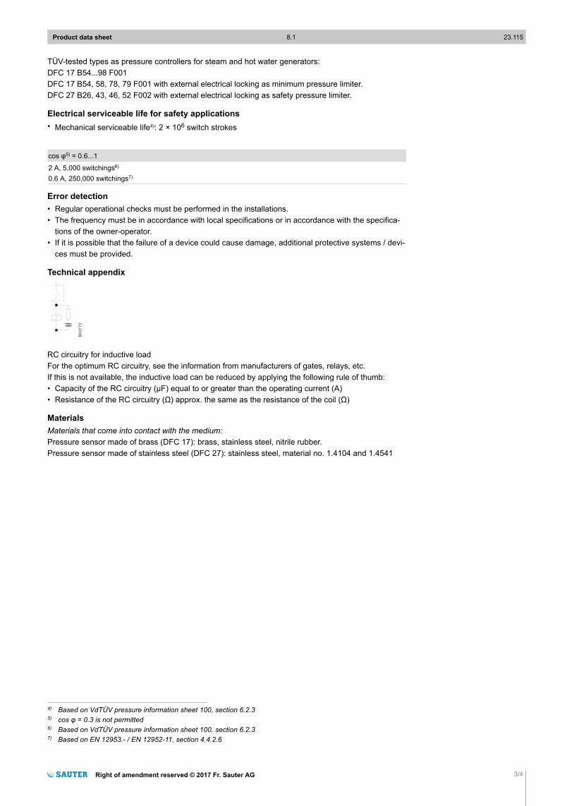
RC circuitry for inductive loadFor the optimum RC circuitry, see the information from manufacturers of gates, relays, etc.If this is not available, the inductive load can be reduced by applying the following rule of thumb:• Capacity of the RC circuitry (µF) equal to or greater than the operating current (A)• Resistance of the RC circuitry (Ω) approx. the same as the resistance of the coil (Ω)
MaterialsMaterials that come into contact with the medium: Pressure sensor made of brass (DFC 17): brass, stainless steel, nitrile rubber.Pressure sensor made of stainless steel (DFC 27): stainless steel, material no. 1.4104 and 1.4541
4) Based on VdTÜV pressure information sheet 100, section 6.2.35) cos φ = 0.3 is not permitted6) Based on VdTÜV pressure information sheet 100, section 6.2.37) Based on EN 12953.- / EN 12952-11, section 4.4.2.6
Product data sheet 8.1 23.115
Right of amendment reserved © 2017 Fr. Sauter AG 3/4
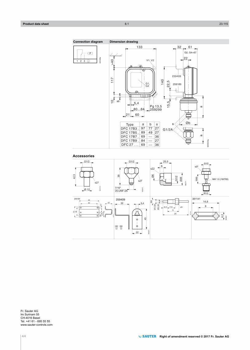
Connection diagram Dimension drawing
A014
99
a
1 2 3
P G2, G4=67
259189
M259344g
133 32 61
22
259409
V1, V2
5,4
80...84
21 60
Pg 13,5259299
Øbs
G1/2A
10 6
11
7>
40
14
0
22
,51
5,5
aa
G1,G2
a
97
89
69
84
69
b
77
49
---
---
---
s
27
27
36
27
36
Type
DFC 17B3 .
DFC 17B5 .
DFC 17B7 .
DFC 17B9 .
DFC 27 . . .
Accessories
42,5
G1/2
Ø 12
M0
0317a
s27
38
7/16"
20-UNF-2A
G1/2
M0
0315
s27
Ø6
G1/2
Ø26
25,5
8s22
M0
077
7
G1/2
1000
R1/2
s27
NW 1.0 (192700)
M0
0318
32
38
50
80
95
5,4
M5 15,5
259189
45
5,432
M0
0314
259409
22
M0
45
66
25
11
s57,54,5
M4
Ø1
,58
Ø0
,38
14,8
4,2
M0
696
2
8
381141
Product data sheet 8.1 23.115
4/4 Right of amendment reserved © 2017 Fr. Sauter AG
Fr. Sauter AGIm Surinam 55CH-4016 BaselTel. +41 61 - 695 55 55www.sauter-controls.com