DeZURIK URETHANE KNIFE GATE VALVES … KGU Technical...Applicable Standards Valve Weights With...
12
DeZURIK URETHANE KNIFE GATE VALVES TECHNICAL SPECIFICATIONS BULLETIN 32.00-2 AUGUST 2011
Transcript of DeZURIK URETHANE KNIFE GATE VALVES … KGU Technical...Applicable Standards Valve Weights With...
DeZURIK URETHANE KNIFE GATE VALVES
TECHNICAL SPECIFICATIONS
BULLETIN 32.00-2
AUGUST 2011

Item Size Range Characteristic/Material
A1Body
All SizesCast iron ASTM A 126, Class B with urethane liner
A2Packing
All SizesC, Square braided PTFE impregnated synthetic fiber
A3 All Sizes
304 stainless steel, ASTM A 240, Type 304
316 stainless steel, ASTM A 240, Type 316
A4 Packing Gland
4" (100 mm)316 stainless steel, ASTM A 743, Grade CF-8M
6-24" (150-600 mm)Ductile iron, ASTM A 536 with P006 plastic coating
A10Seat Material
All Sizes Urethane
B5Yoke Sleeve
4-12" (100-300 mm)Aluminum bronze, ASTM B 148 Alloy C95200
14-24" (350-600 mm)Ductile iron, ASTM A 536, electroless nickel coated
B7Yoke (Superstructure)
All Sizes Carbon steel, ASTM A 36
Materials of Construction
Valve Selection
Urethane Seats Leak tight/zero leakage
ValveSize
DirectPressure
ReversePressure
4-12"100-300 mm
150 psi C.W.P.1030 kPa C.W.P.
150 psi C.W.P.1030 kPa C.W.P.
14-24"350-600mm
50 psi C.W.P.350 kPa C.W.P.
75 psi C.W.P.520 kPa C.W.P.
Shutoff Capabilities
Pressure Rating
Cv/Kv Valves, K Factors, Area of Opening
Valve Sizes
Metal Seated, Round Port
Cv*Kv*
100% OpenK Factor **
Area of Opening(in2/cm2)
4"100 mm
880761 0.30 11
716"
150 mm21901890 0.25 26
1688"
200 mm41903620 0.21 47
30310"
250 mm57604980 0.27 64
41312"
300 mm87607580 0.24 95
61314"
350 mm1160010000 0.21 123
79316"
400 mm1540013300 0.20 162
104518"
450 mm1930016700 0.21 205
132220"
500 mm2460021300 0.20 255
164524"
600 mm3610031200 0.20 374
2412
*Cv = Flow in GPM of water at 1 psi pressure drop. Kv = Flow in m3/hr. of water at 100 kPa pressure drop.**The equivalent length of pipe may be calculated according to the following formula: L=K x D Where: L = Equivalent length of pipe in feet f K = K factor - Resistance coeffiecient of valve D = Pipe diameter in feet f = Friction factor, relating to type of pipe
KGU Urethane Knife Gate ValvesOne-piece cast-in-place urethane liner designed especially for handling abrasive slurries and dry materials in the mining industry. Rugged stainless steel gate, long-life packing, stainless steel stem, corrosion resistant yoke sleeve, and heavy duty superstructure
© 2009 DeZURIK2

Applicable Standards
Valve Weights With Handwheel
DeZURIK KGU Urethane Knife Gate Valves are designed and/or tested to meet the following standards:
ANSI B16.1 (ASA B16.1)8-24" (200 mm-600 mm)
Cast Iron Pipe Flanges and Flanged Fittings, 125 lbs. Conforms to related flange drilling dimensions
ANSI B16.5 2-6" (50-150 mm)
Carbon Steel Flanges and Flanged Fittings, 150 lb. Conforms to related flange drilling dimensions
International StandardsConforms to flanged bolt guides and pressure ratings-JIS 10; DIN 10 and DIN 16; ISO 7005-1/PN 10 and 7005-2/PN 16; BS 4504/ PN16; AS 2129 table D and E
Valve SizesWeightlbs./kg.
4"100 mm
4018
6"150 mm
6329
8"200 mm
10045
10"250 mm
16374
12"300 mm
227103
14"350 mm
287130
16"400 mm
374170
18"450 mm
443170
20"500 mm
574260
24"600 mm
740336
Cylinder Weights
Cylinder SizesWeightlbs./kg.
CY-PC4 4018
CY-PC6 6329
CY-PC8 10045
CY-PC10 16374
CY-PC12 227103
Add these weights to valve and handwheel weights.
OrderingTo order, simply complete the valve order code from information shown. An ordering examples is shown for your reference.
4 = 4" (100 mm)6 = 6" (150 mm)8 = 8" (200 mm)10 = 10" (250 mm)12 = 12" (300 mm)14 = 14" (350 mm)16 = 16" (400 mm)18 = 18" (450 mm)20 = 20" (500 mm)24 = 24" (600 mm)
Valve SizeGive valve size code as follows:
Valve StyleGive valve style code as follows: KGU = Urethane Knife Gate Valves Note: Temperature limits of Urethane are -40˚ to 180˚ F (-40˚ to 82˚C)
W1 = Wafer, ANSI 150W110 = Wafer, ISO 7005-/PN10 and 7500-2/PN16,
DIN 10 or BS4504/PN10W116 = Wafer, ISO 7005-/PN10 and 7500-2/PN16,
DIN 16 or BS4504/PN16Not available on 8, 18, 20 and 24" (200, 450, 500 and 600 mm valves)
W1J1 = Wafer, JIS10 (Not available on 8" (200 mm))W1DA = Wafer, AS2129 Table DW1EA = Wafer, AS2129 Table EW1T = Wafer, ANSI 150 with through bolting flange
End ConnectionGive end connection code as follows:
S1 = 304 Stainless SteelS2 = 316 Stainless Steel
Gate MaterialGive gate material code as follows:
C = Square braided PTPE Impregnated Synthetic Fiber to 500˚F (260˚C)
Packing MaterialGive packing material code as follows:
Order Example:KGU, 4, W1, S2, C*MN-HD8
3
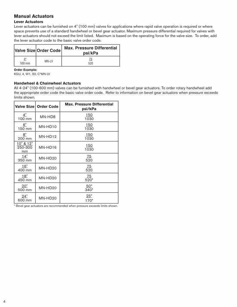
Manual Actuators
Valve Size Order CodeMax. Pressure Differential
psi/kPa4"
100 mmMN-LV
75520
Lever ActuatorsLever actuators can be furnished on 4" (100 mm) valves for applications where rapid valve operation is required or where space prevents use of a standard handwheel or bevel gear actuator. Maximum pressure differential required for valves with lever actuators should not exceed the limit listed. Maximum is based on the operating force for the valve size. To order, add the lever actuator code to the basic valve order code.
Handwheel & Chainwheel ActuatorsAll 4-24" (100-600 mm) valves can be furnished with handwheel or bevel gear actuators. To order rotary handwheel add the appropriate order code the basic valve order code. Refer to information on bevel gear actuators when pressure exceeds limits shown.
Valve Size Order CodeMax. Pressure Differential
psi/kPa
4"100 mm MN-HD8 150
1030
6"150 mm MN-HD10 150
1030
8"200 mm MN-HD12 150
103010" & 12"250-300
mmMN-HD16 150
1030
14"350 mm MN-HD20 75
520
16"400 mm MN-HD20 75
520
18"450 mm MN-HD20 75
520*
20"500 mm MN-HD20 50*
340*
24"600 mm MN-HD20
25*170*
* Bevel gear actuators are recommended when pressure exceeds limits shown.
Order Example:KGU, 4, W1, S2, C*MN-LV
4
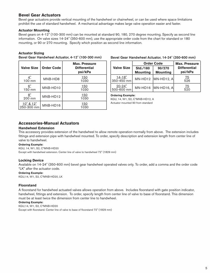
Bevel Gear ActuatorsBevel gear actuators provide vertical mounting of the handwheel or chainwheel, or can be used where space limitations prohibit the use of standard handwheel. A mechanical advantage makes large valve operation easier and faster.
Actuator MountingBevel gears on 4-12" (100-300 mm) can be mounted at standard 90, 180, 270 degree mounting. Specify as second line information. On valve sizes 14-24" (350-600 mm), use the appropriate order code from the chart for standard or 180 mounting, or 90 or 270 mounting. Specify which position as second line information.
Valve Size Order CodeMax. Pressure
Differentialpsi/kPa
4"100 mm MNB-HD8 150
1030
6"150 mm MNB-HD10 150
1030
8"200 mm MNB-HD12 150
1030
10" & 12"250-300 mm MNB-HD16 150
1030
Actuator SizingBevel Gear Handwheel Actuator, 4-12" (100-300 mm) Bevel Gear Handwheel Actuator, 14-24" (350-600 mm)
Valve SizeOrder Code Max. Pressure
Differentialpsi/kPa
Std./180 Mounting
90/270 Mounting
14-18"350-450 mm MN-HD12 MN-HD12, A 75
526
20-24"500-600 mm MN-HD16 MN-HD16, A 75
520
Ordering Example:KGU, 14, W1, S2, C*MNB-HD12, AActuator mounted 90 from standard
Accessories-Manual ActuatorsHandwheel ExtensionThis accessory provides extension of the handwheel to allow remote operation-normally from above. The extension includes fittings and extension pipe with handwheel mounted. To order, specify description and extension length from center line of valve to handwheel.Ordering Example:KGU, 14, W1, S2, C*MNB-HD20Except with handwheel extension. Center line of valve to handwheel 72" (1829 mm)
Available on 14-24" (350-600 mm) bevel gear handwheel operated valves only. To order, add a comma and the order code “LK" after the actuator code.
Locking Device
Ordering Example:KGU,14, W1, S2, C*MNB-HD20, LK
FloorstandA floorstand for handwheel actuated valves allows operation from above. Includes floorstand with gate position indicator, handwheel, fittings and extension. To order, specify length from center line of valve to base of floorstand. This dimension must be at least twice the dimension from center line to handwheel.Ordering Example:KGU,14, W1, S2, C*MNB-HD20Except with floorstand. Center line of valve to base of floorstand 72" (1829 mm)
5
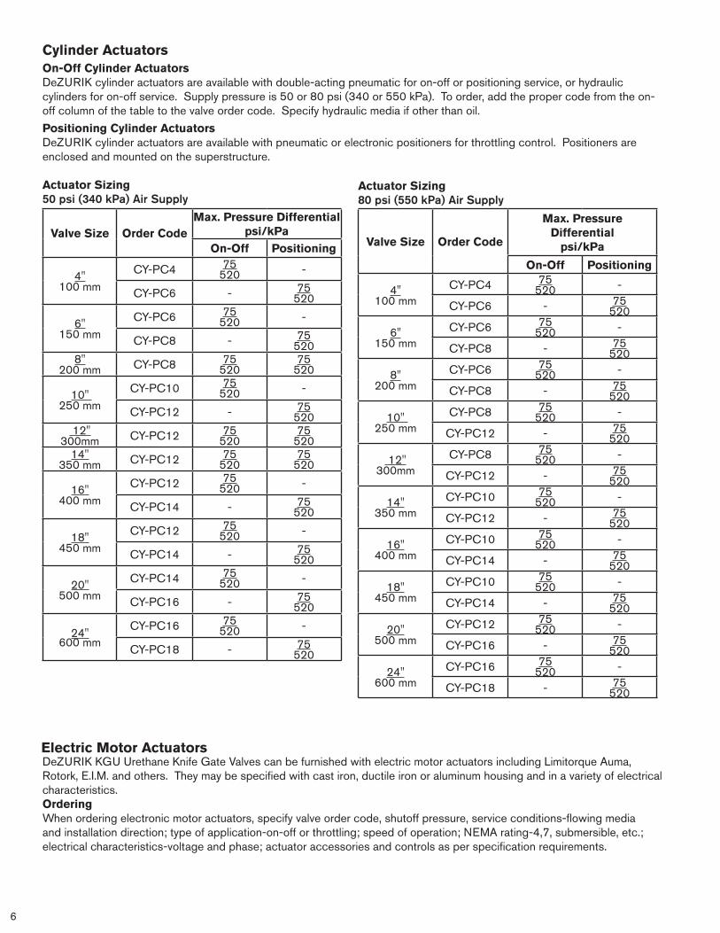
Cylinder ActuatorsOn-Off Cylinder ActuatorsDeZURIK cylinder actuators are available with double-acting pneumatic for on-off or positioning service, or hydraulic cylinders for on-off service. Supply pressure is 50 or 80 psi (340 or 550 kPa). To order, add the proper code from the on-off column of the table to the valve order code. Specify hydraulic media if other than oil.
Positioning Cylinder ActuatorsDeZURIK cylinder actuators are available with pneumatic or electronic positioners for throttling control. Positioners are enclosed and mounted on the superstructure.
Valve Size Order CodeMax. Pressure Differential
psi/kPa
On-Off Positioning
4"100 mm
CY-PC4 75520 -
CY-PC6 - 75520
6"150 mm
CY-PC6 75520 -
CY-PC8 - 75520
8"200 mm CY-PC8 75
52075
520
10" 250 mm
CY-PC10 75520 -
CY-PC12 - 75520
12"300mm CY-PC12 75
52075
52014"
350 mm CY-PC12 75520
75520
16"400 mm
CY-PC12 75520 -
CY-PC14 - 75520
18"450 mm
CY-PC12 75520 -
CY-PC14 - 75520
20"500 mm
CY-PC14 75520 -
CY-PC16 - 75520
24"600 mm
CY-PC16 75520 -
CY-PC18 - 75520
Actuator Sizing50 psi (340 kPa) Air Supply
Valve Size Order Code
Max. Pressure Differential
psi/kPa
On-Off Positioning
4"100 mm
CY-PC4 75520 -
CY-PC6 - 75520
6"150 mm
CY-PC6 75520 -
CY-PC8 - 75520
8"200 mm
CY-PC6 75520 -
CY-PC8 - 75520
10" 250 mm
CY-PC8 75520 -
CY-PC12 - 75520
12"300mm
CY-PC8 75520 -
CY-PC12 - 75520
14"350 mm
CY-PC10 75520 -
CY-PC12 - 75520
16"400 mm
CY-PC10 75520 -
CY-PC14 - 75520
18"450 mm
CY-PC10 75520 -
CY-PC14 - 75520
20"500 mm
CY-PC12 75520 -
CY-PC16 - 75520
24"600 mm
CY-PC16 75520 -
CY-PC18 - 75520
Actuator Sizing80 psi (550 kPa) Air Supply
Electric Motor ActuatorsDeZURIK KGU Urethane Knife Gate Valves can be furnished with electric motor actuators including Limitorque Auma, Rotork, E.I.M. and others. They may be specified with cast iron, ductile iron or aluminum housing and in a variety of electrical characteristics.OrderingWhen ordering electronic motor actuators, specify valve order code, shutoff pressure, service conditions-flowing media and installation direction; type of application-on-off or throttling; speed of operation; NEMA rating-4,7, submersible, etc.; electrical characteristics-voltage and phase; actuator accessories and controls as per specification requirements.
6
AccessoriesPositionersDeZURIK cylinder actuators are available with pneumatic or electronic positioners for throttling control. Positioners are enclosed and mounted on the superstructure.
Air Filter RegulatorThe DeZURIK Air Filter Regulator is designed to provide clean, accurate air pressure to actuators and positioners.
Manual Loading Station Control PanelFor all positioning pneumatic actuators. Output is 0-15 psi (0-100 kPa). It includes signal output gauge and pressure reducing valve. Order as a separate item by giving code ACC*CNP025.Ordering Example:ACC*CNP025
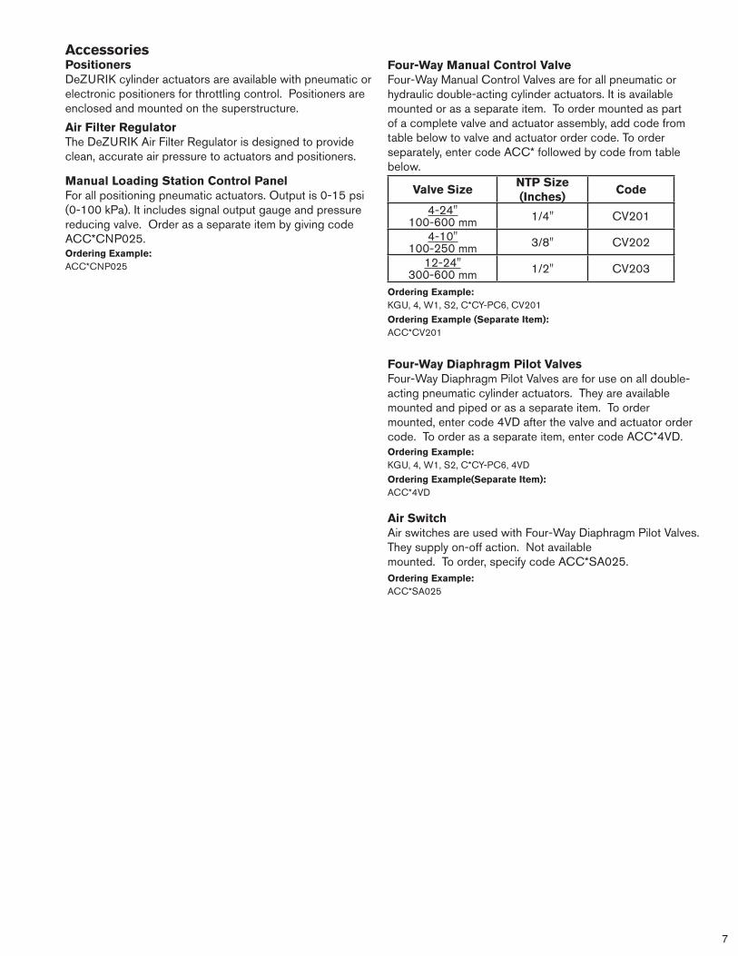
Four-Way Manual Control ValveFour-Way Manual Control Valves are for all pneumatic or hydraulic double-acting cylinder actuators. It is available mounted or as a separate item. To order mounted as part of a complete valve and actuator assembly, add code from table below to valve and actuator order code. To order separately, enter code ACC* followed by code from table below.
Four-Way Diaphragm Pilot ValvesFour-Way Diaphragm Pilot Valves are for use on all double-acting pneumatic cylinder actuators. They are available mounted and piped or as a separate item. To order mounted, enter code 4VD after the valve and actuator order code. To order as a separate item, enter code ACC*4VD.
Valve SizeNTP Size (Inches)
Code
4-24"100-600 mm 1/4" CV201
4-10"100-250 mm 3/8" CV202
12-24"300-600 mm 1/2" CV203
Ordering Example:KGU, 4, W1, S2, C*CY-PC6, CV201
Ordering Example (Separate Item):ACC*CV201
Ordering Example:KGU, 4, W1, S2, C*CY-PC6, 4VD
Ordering Example(Separate Item):ACC*4VD
Air SwitchAir switches are used with Four-Way Diaphragm Pilot Valves. They supply on-off action. Not available mounted. To order, specify code ACC*SA025.Ordering Example:ACC*SA025
7
Four-Way Solenoid ValvesSolenoid valves may be ordered mounted and piped as part of a complete valve/actuator assembly or they can be ordered as a separate item.
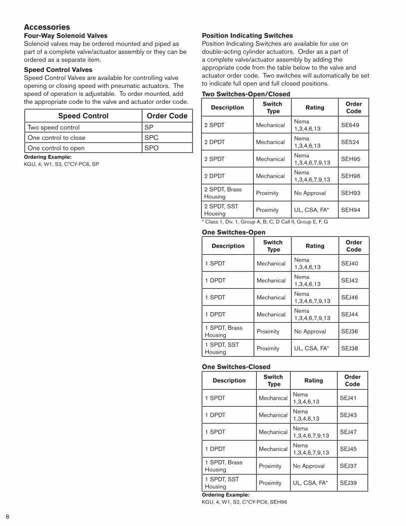
AccessoriesPosition Indicating SwitchesPosition Indicating Switches are available for use on double-acting cylinder actuators. Order as a part of a complete valve/actuator assembly by adding the appropriate code from the table below to the valve and actuator order code. Two switches will automatically be set to indicate full open and full closed positions.
Speed Control ValvesSpeed Control Valves are available for controlling valve opening or closing speed with pneumatic actuators. The speed of operation is adjustable. To order mounted, add the appropriate code to the valve and actuator order code.
DescriptionSwitch Type
RatingOrder Code
2 SPDT MechanicalNema 1,3,4,6,13
SE649
2 DPDT MechanicalNema 1,3,4,6,13
SE524
2 SPDT MechanicalNema 1,3,4,6,7,9,13
SEH95
2 DPDT MechanicalNema 1,3,4,6,7,9,13
SEH96
2 SPDT, Brass Housing
Proximity No Approval SEH93
2 SPDT, SST Housing
Proximity UL, CSA, FA* SEH94
Two Switches-Open/Closed
DescriptionSwitch Type
RatingOrder Code
1 SPDT MechanicalNema 1,3,4,6,13
SEJ40
1 DPDT MechanicalNema 1,3,4,6,13
SEJ42
1 SPDT MechanicalNema 1,3,4,6,7,9,13
SEJ46
1 DPDT MechanicalNema 1,3,4,6,7,9,13
SEJ44
1 SPDT, Brass Housing
Proximity No Approval SEJ36
1 SPDT, SST Housing
Proximity UL, CSA, FA* SEJ38
One Switches-Open
DescriptionSwitch Type
RatingOrder Code
1 SPDT MechanicalNema 1,3,4,6,13
SEJ41
1 DPDT MechanicalNema 1,3,4,6,13
SEJ43
1 SPDT MechanicalNema 1,3,4,6,7,9,13
SEJ47
1 DPDT MechanicalNema 1,3,4,6,7,9,13
SEJ45
1 SPDT, Brass Housing
Proximity No Approval SEJ37
1 SPDT, SST Housing
Proximity UL, CSA, FA* SEJ39
One Switches-Closed
Ordering Example:KGU, 4, W1, S2, C*CY-PC6, SEH96
Speed Control Order Code
Two speed control SP
One control to close SPC
One control to open SPOOrdering Example:KGU, 4, W1, S2, C*CY-PC6, SP
* Class 1, Div. 1, Group A, B, C, D Call II, Group E, F, G
8
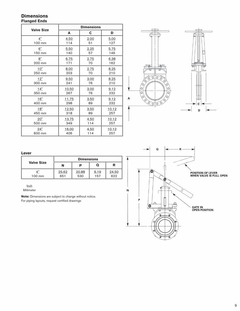
DimensionsFlanged Ends
Valve SizeDimensions
A C D
4"100 mm
4.50114
2.0051
5.00127
6"150 mm
5.50140
2.2557
5.75146
8"200 mm
6.75171
2.7570
6.38162
10"250 mm
8.00203
2.7570
8.25210
12"300 mm
9.50241
3.0076
8.25210
14"350 mm
10.50267
3.0076
9.12232
16"400 mm
11.75298
3.5089
9.12232
18"450 mm
12.50318
3.5089
10.12257
20"500 mm
13.75349
4.50114
10.12257
24"600 mm
16.00406
4.50114
10.12257
Lever
Valve SizeDimensions
N P Q R
4"100 mm
25.62651
20.88530
6.19157
24.50622
InchMillimeter
Note: Dimensions are subject to change without notice.For piping layouts, request certified drawings
9

DimensionsBevel Gear Actuator, 4-12" (100-300 mm)
Valve SizeDimensions
N P Q R
4"100 mm
19.00483
15.94405
8.00203
10.00254
6"150 mm
24.31618
19.31491
10.00254
10.25260
8"200 mm
30.25768
23.25591
12.00305
10.25260
10"250 mm
36.62930
27.69703
16.00406
10.31262
12"300 mm
42.501080
31.50800
16.00406
10.31262
InchMillimeter
Bevel Gear Actuator, 14-24" (350-600 mm)
Valve Size
Dimensions
N PQ R
Std. & 180 90 & 270 Std. & 180 90 & 270
14"350 mm
53.001402
56.651439
36.25972
39.751010
12.00305
9.62244
16"400 mm
57.251491
60.781544
40.381061
43.881115
12.00305
9.62244
18"450 mm
68.811715
71.381813
46.901159
49.401255
12.00305
9.62244
20"500 mm
72.721948
75.831926
50.811391
54.061373
16.00406
9.62244
24"600 mm
83.962146
87.252216
59.031512
62.281582
16.00406
9.62244
InchMillimeter
10

DimensionsCylinder Actuators
Valve Size Actuator CodeDimension
Q
4-8"100-200 mm
CY-PC48.38213
4-8"100-200 mm
CY-PC68.38213
6-12"150-300 mm
CY-PC810.25260
10-12"250-300 mm
CY-PC10
14.00356
14-20"350-500 mm
12.31313
10-12"250-300 mm
CY-PC12
14.00356
14-24"350-600 mm
14.88378
16-24"400-600 mm
CY-PC1414.75375
18-24"450-600 mm
CY-PC1617.00432
24"600 mm
CY-PC1819.00483
Valve SizeDimension
CY-PC4 CY-PC6 CY-PC8 CY-PC10 CY-PC12 CY-PC14 CY-PC16 CY-PC18
4"100 mm
23.12587
24.25616
- - - - - -
6"150 mm
-29.69754
30.50775
- - - - -
8"200 mm
-35.50902
36.56929
- - - - -
10"250 mm
- -43.621108
43.561107
45.441154
- - -
12"300 mm
- -49.311253
49.121248
50.811291
- - -
14"350 mm
- - -56.621438
58.441484
- - -
16"400 mm
- - -62.561589
64.381635
69.191732
- -
18"450 mm
- - -70.691796
72.501842
76.691948
77.061957
-
20"500 mm
- - - -78.251988
82.622099
83.002108
-
24"600 mm
- - - -89.752280
94.942412
95.312421
95.812434
11

DimensionsHandwheel Actuators
Valve SizeDimensions
N P Q
4"100 mm
19.00483
16.25413
8.00203
6"150 mm
24.31618
19.75502
10.00254
8"200 mm
30.25768
23.69602
12.00305
10"250 mm
36.62930
28.00711
16.00406
12"300 mm
42.501080
31.88810
16.00406
14"350 mm
51.501308
38.25972
20.00508
16"400 mm
55.501410
40.311024
20.00508
18"450 mm
66.001676
48.621235
20.00508
20"500 mm
69.751772
50.621286
20.00508
24"600 mm
81.752076
58.501486
20.00508
DeZURIK, Inc. reserves the right to incorporate our latest design and material changes without notice or obligation. Design features, materials of construction and dimensional data, as described in this bulletin, are provided for your information only
and should not be relied upon unless confirmed in writing by DeZURIK, Inc. Certified drawings are available upon request.
Printed in the U.S.A.
250 Riverside Ave. N. Sartell, Minnesota 56377 • Phone: 320-259-2000 • Fax: 320-259-2227
For information about our worldwide locations, approvals, certifications and local representative:Web Site: www.dezurik.com E-Mail: [email protected]
Sales and Service