DEXTER S HEAVY DUTY D200 SERIES - Sauber Mfgns 008-396-08 1 Assy Hub 8 Stud on 275mm ABS Includes...
36
DEXTER’ S HEAVY DUTY D200 SERIES www.dexteraxle.com
Transcript of DEXTER S HEAVY DUTY D200 SERIES - Sauber Mfgns 008-396-08 1 Assy Hub 8 Stud on 275mm ABS Includes...
DEXTER’S HEAVY DUTY D200 SERIES
w ww.dexteraxle.com
www.dexteraxle.com2900 Industrial Parkway East • Elkhart, IN 46516
Fax: 574-295-8666 • Ph. 574-295-7888
7/05 © Dexter Axle 2005LIT-121-00
Introduction
This information is intended as a guide for the proper specification and application of Dexter Axle running gear, associatedcomponents and accessories.
Dexter offers a full line of trailer axles that can be used in many different applications. When specifying any pre-engineered components such as axles, it is the responsibility of the trailer designer to insure compatibility with thevehicle and all of its sub-systems.
Important InformationThe information presented is meant to assist trailer manufacturers in the specification of their running gear components.Dexter Axle does not warrant that the information given constitutes an approved trailer design or application. Dynamicloading, travel requirements unique to the trailer design, unusual service conditions, trailer configurations, unequal loaddistribution, hitch or coupler arrangements and towing vehicle suspension characteristics can significantly affect theperformance of any trailer axle and/or suspension systems. It remains the responsibility of the trailer manufacturer toevaluate, specify and test their trailer/running gear combination before production and to certify it as such. While theinformation presented at the time of this writing is current, it is subject to change as designs and components evolve overtime.
Disclaimer of Warranty and Limitation of LiabilityAll users of this product catalog acknowledge that the information presented is significantly affected by factors within theexclusive knowledge of the user including, among other things, service conditions, trailer configurations, load distributions,hitch and coupler arrangements and tow vehicle suspension characteristics, that the users have independently investigatedthese factors and have solely relied on those investigations when using this catalog, and that it is the responsibility of theuser to adequately specify, evaluate and test its trailer/running gear combinations
.
DEXTER AXLE DISCLAIMS ALL WARRANTIES, WHETHER WRITTEN, ORAL OR IMPLIED, IN FACT OR IN LAW (INCLUDINGANY WARRANTY OF MERCHANTABILITY OR FITNESS FOR A PARTICULAR PURPOSE), ASSOCIATED WITH THE USE OFTHE CATALOG AND WITH ANY INFORMATION PRESENTED BY THIS CATALOG.
Dexter Axle shall not be liable in damages (whether compensatory, punitive, direct, indirect, special, incidental orconsequential) to any user of this catalog under contract, tort, strict liability or any other theory of liability, and any useragrees to indemnify and hold Dexter Axle harmless from any and all claims, actions or other proceedings (including attorneyfees and court costs) arising out of the use of this catalog to the extent said claims, actions or other proceedings do notarise out of the sole and exclusive negligence of Dexter Axle.
Load Ratings The maximum load carrying capacity of any assembly is limited to the lowest load rating of any individual componentselected. For instance, the load rating of a pair of wheels may be lower than other axle components selected. If this is thecase, the load carrying capacity of the axle assembly is reduced accordingly. As a specific example, if a pair of wheels israted at 1500 pounds each and is used with other components rated at 4000 pounds per axle, the maximum load capacityis limited to 3000 pounds. If two tires are rated at 1400 pounds each and are used on this assembly, the maximum loadcarrying capacity is limited to 2800 pounds.
Table of Contents
1
Models and Capacities22,500 - 27,500 Lbs. . . . . . . . . . . . . . . . . . . . . . . . . . . . . . . . . . . . . . . . . . . . . . . . . . . . . . . . . . . . . . . . . .2
Hubs and Drums121/4" x 71/2" Brake Size . . . . . . . . . . . . . . . . . . . . . . . . . . . . . . . . . . . . . . . . . . . . . . . . . . . . . . . . . . . . . . . .3161/2" x 7" Brake Size . . . . . . . . . . . . . . . . . . . . . . . . . . . . . . . . . . . . . . . . . . . . . . . . . . . . . . . . . . . . . . . . .6Cross Reference . . . . . . . . . . . . . . . . . . . . . . . . . . . . . . . . . . . . . . . . . . . . . . . . . . . . . . . . . . . . . . . . . . .10Anti-Lock Braking Systems (ABS) . . . . . . . . . . . . . . . . . . . . . . . . . . . . . . . . . . . . . . . . . . . . . . . . . . . . . .12
Tires & WheelsClearances and Dimensions . . . . . . . . . . . . . . . . . . . . . . . . . . . . . . . . . . . . . . . . . . . . . . . . . . . . . . . . . .13Application Information . . . . . . . . . . . . . . . . . . . . . . . . . . . . . . . . . . . . . . . . . . . . . . . . . . . . . . . . . . . . . .14
Tandem Air SystemTandem Air System . . . . . . . . . . . . . . . . . . . . . . . . . . . . . . . . . . . . . . . . . . . . . . . . . . . . . . . . . . . . . . . . .17
Axle/Brake Components121/4" x 71/2" Brake Size . . . . . . . . . . . . . . . . . . . . . . . . . . . . . . . . . . . . . . . . . . . . . . . . . . . . . . . . . . . . . . .18161/2" x 7" Brake Size . . . . . . . . . . . . . . . . . . . . . . . . . . . . . . . . . . . . . . . . . . . . . . . . . . . . . . . . . . . . . . . .20
Camshafts121/4" x 71/2" Brake Size . . . . . . . . . . . . . . . . . . . . . . . . . . . . . . . . . . . . . . . . . . . . . . . . . . . . . . . . . . . . . . .22161/2" x 7" Brake Size . . . . . . . . . . . . . . . . . . . . . . . . . . . . . . . . . . . . . . . . . . . . . . . . . . . . . . . . . . . . . . . .23
Air ChambersService Air Chambers . . . . . . . . . . . . . . . . . . . . . . . . . . . . . . . . . . . . . . . . . . . . . . . . . . . . . . . . . . . . . . .24Spring Brake Air Chambers . . . . . . . . . . . . . . . . . . . . . . . . . . . . . . . . . . . . . . . . . . . . . . . . . . . . . . . . . . .25Tandem Axle Configurations . . . . . . . . . . . . . . . . . . . . . . . . . . . . . . . . . . . . . . . . . . . . . . . . . . . . . . . . . .26
SuspensionsH-9700 Underslung . . . . . . . . . . . . . . . . . . . . . . . . . . . . . . . . . . . . . . . . . . . . . . . . . . . . . . . . . . . . . . . . .28H-9700 Overslung . . . . . . . . . . . . . . . . . . . . . . . . . . . . . . . . . . . . . . . . . . . . . . . . . . . . . . . . . . . . . . . . . .29
Limited WarrantyDexter Axle Limited Warranty . . . . . . . . . . . . . . . . . . . . . . . . . . . . . . . . . . . . . . . . . . . . . . . . . . . . . . . . .30
Models and CapacitiesM
OD
EL
S A
ND
CA
PA
CIT
IES
22
,50
0 –
27
,50
0 L
BS
.
2
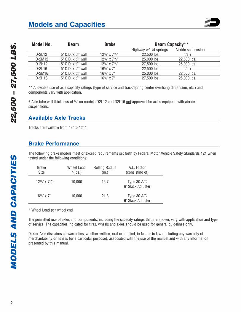
Model No. Beam Brake Beam Capacity**Highway w/leaf springs Airride suspension
D-2L12 5" O.D. x 1/2" wall 121/4" x 71/2" 22,500 lbs. n/a +D-2M12 5" O.D. x 5/8" wall 121/4" x 71/2" 25,000 lbs. 22,500 lbs. D-2H12 5" O.D. x 3/4" wall 121/4" x 71/2" 27,500 lbs. 25,000 lbs. D-2L16 5" O.D. x 1/2" wall 161/2" x 7" 22,500 lbs. n/a +D-2M16 5" O.D. x 5/8" wall 161/2" x 7" 25,000 lbs. 22,500 lbs.D-2H16 5" O.D. x 3/4" wall 161/2" x 7" 27,500 lbs. 25,000 lbs.
** Allowable use of axle capacity ratings (type of service and track/spring center overhang dimension, etc.) and components vary with application.
+ Axle tube wall thickness of 1/2" on models D2L12 and D2L16 not approved for axles equipped with airride suspensions.
Available Axle Tracks
Tracks are available from 48" to 124".
Brake Performance
The following brake models meet or exceed requirements set forth by Federal Motor Vehicle Safety Standards 121 whentested under the following conditions:
Brake Wheel Load Rolling Radius A.L. FactorSize *(lbs.) (in.) (consisting of)
121/4" x 71/2" 10,000 15.7 Type 30 A/C6" Slack Adjuster
161/2" x 7" 10,000 21.3 Type 30 A/C6" Slack Adjuster
* Wheel Load per wheel end
The permitted use of axles and components, including the capacity ratings that are shown, vary with application and typeof service. The capacities indicated for tires, wheels and axles should be used for general guidelines only.
Dexter Axle disclaims all warranties, whether written, oral or implied, in fact or in law (including any warranty of merchantability or fitness for a particular purpose), associated with the use of the manual and with any information presented by this manual.
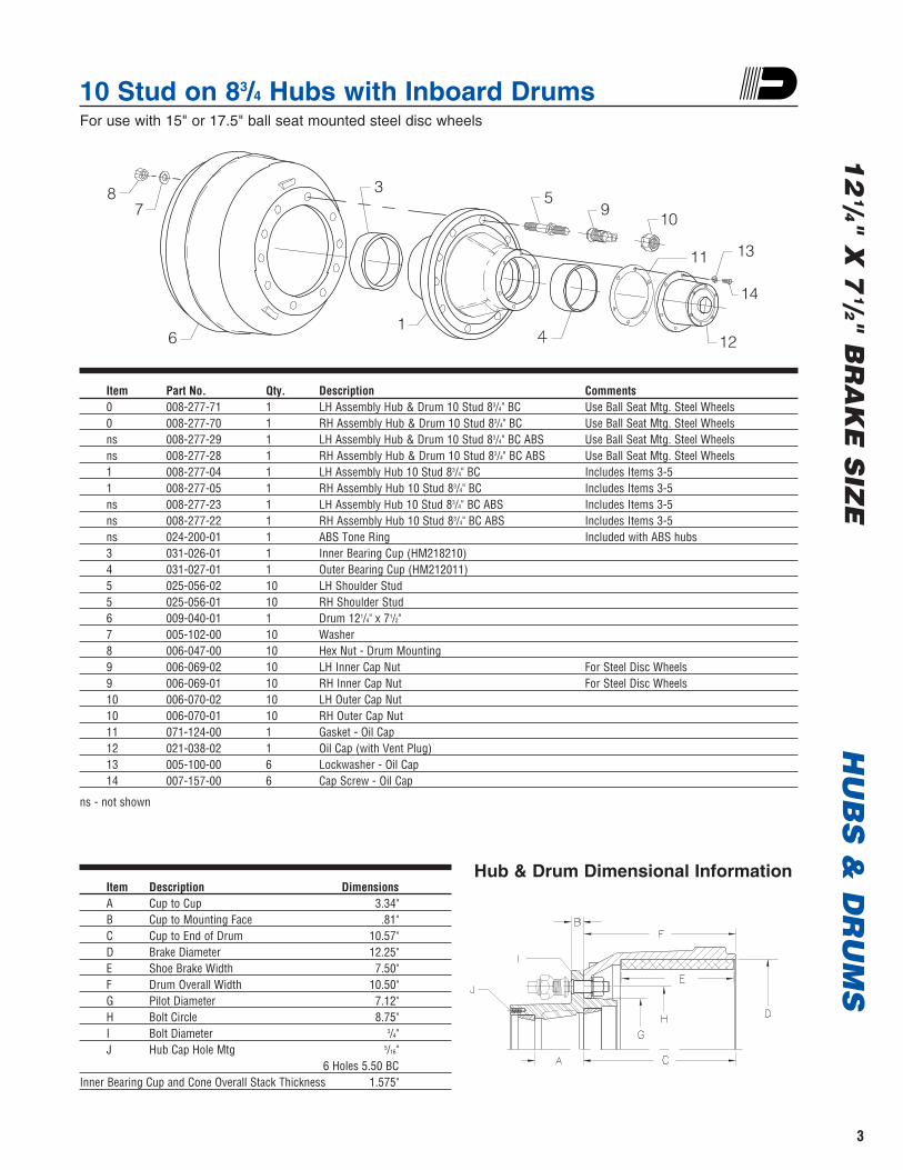
10 Stud on 83/4 Hubs with Inboard Drums For use with 15" or 17.5" ball seat mounted steel disc wheels
HU
BS
& D
RU
MS
12
1/4" X 7
1/2" BR
AK
E S
IZE
3
Item Part No. Qty. Description Comments0 008-277-71 1 LH Assembly Hub & Drum 10 Stud 83/4" BC Use Ball Seat Mtg. Steel Wheels0 008-277-70 1 RH Assembly Hub & Drum 10 Stud 83/4" BC Use Ball Seat Mtg. Steel Wheelsns 008-277-29 1 LH Assembly Hub & Drum 10 Stud 83/4" BC ABS Use Ball Seat Mtg. Steel Wheelsns 008-277-28 1 RH Assembly Hub & Drum 10 Stud 83/4" BC ABS Use Ball Seat Mtg. Steel Wheels1 008-277-04 1 LH Assembly Hub 10 Stud 83/4" BC Includes Items 3-51 008-277-05 1 RH Assembly Hub 10 Stud 83/4" BC Includes Items 3-5ns 008-277-23 1 LH Assembly Hub 10 Stud 83/4" BC ABS Includes Items 3-5ns 008-277-22 1 RH Assembly Hub 10 Stud 83/4" BC ABS Includes Items 3-5ns 024-200-01 1 ABS Tone Ring Included with ABS hubs3 031-026-01 1 Inner Bearing Cup (HM218210)4 031-027-01 1 Outer Bearing Cup (HM212011)5 025-056-02 10 LH Shoulder Stud5 025-056-01 10 RH Shoulder Stud6 009-040-01 1 Drum 121/4" x 71/2"7 005-102-00 10 Washer8 006-047-00 10 Hex Nut - Drum Mounting9 006-069-02 10 LH Inner Cap Nut For Steel Disc Wheels9 006-069-01 10 RH Inner Cap Nut For Steel Disc Wheels10 006-070-02 10 LH Outer Cap Nut10 006-070-01 10 RH Outer Cap Nut11 071-124-00 1 Gasket - Oil Cap12 021-038-02 1 Oil Cap (with Vent Plug)13 005-100-00 6 Lockwasher - Oil Cap14 007-157-00 6 Cap Screw - Oil Cap
ns - not shown
87
6
3
1
59
10
11 13
14
12
Item Description DimensionsA Cup to Cup 3.34"B Cup to Mounting Face .81"C Cup to End of Drum 10.57"D Brake Diameter 12.25"E Shoe Brake Width 7.50"F Drum Overall Width 10.50"G Pilot Diameter 7.12"H Bolt Circle 8.75"I Bolt Diameter 3/4" J Hub Cap Hole Mtg 5/16"
6 Holes 5.50 BCInner Bearing Cup and Cone Overall Stack Thickness 1.575"
Hub & Drum Dimensional Information
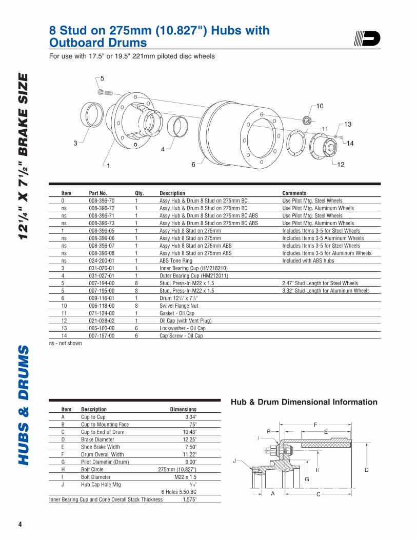
8 Stud on 275mm (10.827") Hubs withOutboard Drums For use with 17.5" or 19.5" 221mm piloted disc wheels
HU
BS
& D
RU
MS
12
1 /4"
X 7
1 /2"
BR
AK
E S
IZE
4
Item Part No. Qty. Description Comments0 008-396-70 1 Assy Hub & Drum 8 Stud on 275mm BC Use Pilot Mtg. Steel Wheelsns 008-396-72 1 Assy Hub & Drum 8 Stud on 275mm BC Use Pilot Mtg. Aluminum Wheelsns 008-396-71 1 Assy Hub & Drum 8 Stud on 275mm BC ABS Use Pilot Mtg. Steel Wheelsns 008-396-73 1 Assy Hub & Drum 8 Stud on 275mm BC ABS Use Pilot Mtg. Aluminum Wheels1 008-396-05 1 Assy Hub 8 Stud on 275mm Includes Items 3-5 for Steel Wheelsns 008-396-06 1 Assy Hub 8 Stud on 275mm Includes Items 3-5 Aluminum Wheelsns 008-396-07 1 Assy Hub 8 Stud on 275mm ABS Includes Items 3-5 for Steel Wheelsns 008-396-08 1 Assy Hub 8 Stud on 275mm ABS Includes Items 3-5 for Aluminum Wheelsns 024-200-01 1 ABS Tone Ring Included with ABS hubs3 031-026-01 1 Inner Bearing Cup (HM218210)4 031-027-01 1 Outer Bearing Cup (HM212011)5 007-194-00 8 Stud, Press-In M22 x 1.5 2.47" Stud Length for Steel Wheels5 007-195-00 8 Stud, Press-In M22 x 1.5 3.32" Stud Length for Aluminum Wheels6 009-116-01 1 Drum 121/4" x 71/2"10 006-118-00 8 Swivel Flange Nut11 071-124-00 1 Gasket - Oil Cap12 021-038-02 1 Oil Cap (with Vent Plug)13 005-100-00 6 Lockwasher - Oil Cap14 007-157-00 6 Cap Screw - Oil Cap
ns - not shown
Item Description DimensionsA Cup to Cup 3.34"B Cup to Mounting Face .75"C Cup to End of Drum 10.43"D Brake Diameter 12.25"E Shoe Brake Width 7.50"F Drum Overall Width 11.22"G Pilot Diameter (Drum) 9.00"H Bolt Circle 275mm (10.827")I Bolt Diameter M22 x 1.5J Hub Cap Hole Mtg 5/16"
6 Holes 5.50 BCInner Bearing Cup and Cone Overall Stack Thickness 1.575"
5
3
1
4
6
1113
14
12
10
J
IB
G
H D
A
FF
CC
Hub & Drum Dimensional Information
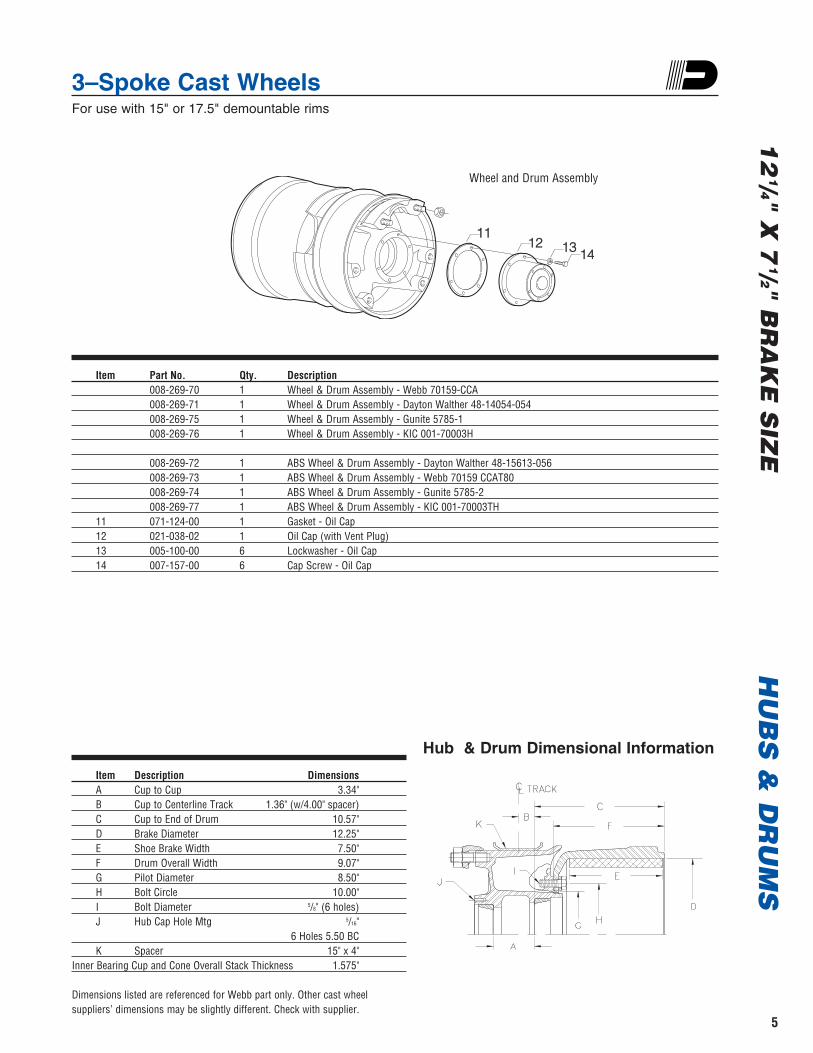
3–Spoke Cast Wheels For use with 15" or 17.5" demountable rims
HU
BS
& D
RU
MS
12
1/4" X 7
1/2" BR
AK
E S
IZE
5
11111212 1313 1414
Item Part No. Qty. Description008-269-70 1 Wheel & Drum Assembly - Webb 70159-CCA008-269-71 1 Wheel & Drum Assembly - Dayton Walther 48-14054-054008-269-75 1 Wheel & Drum Assembly - Gunite 5785-1008-269-76 1 Wheel & Drum Assembly - KIC 001-70003H
008-269-72 1 ABS Wheel & Drum Assembly - Dayton Walther 48-15613-056008-269-73 1 ABS Wheel & Drum Assembly - Webb 70159 CCAT80008-269-74 1 ABS Wheel & Drum Assembly - Gunite 5785-2008-269-77 1 ABS Wheel & Drum Assembly - KIC 001-70003TH
11 071-124-00 1 Gasket - Oil Cap12 021-038-02 1 Oil Cap (with Vent Plug)13 005-100-00 6 Lockwasher - Oil Cap14 007-157-00 6 Cap Screw - Oil Cap
Wheel and Drum Assembly
Item Description DimensionsA Cup to Cup 3.34"B Cup to Centerline Track 1.36" (w/4.00" spacer)C Cup to End of Drum 10.57"D Brake Diameter 12.25"E Shoe Brake Width 7.50"F Drum Overall Width 9.07"G Pilot Diameter 8.50"H Bolt Circle 10.00"I Bolt Diameter 5/8" (6 holes)J Hub Cap Hole Mtg 5/16"
6 Holes 5.50 BCK Spacer 15" x 4"
Inner Bearing Cup and Cone Overall Stack Thickness 1.575"
Dimensions listed are referenced for Webb part only. Other cast wheel suppliers’ dimensions may be slightly different. Check with supplier.
Hub & Drum Dimensional Information
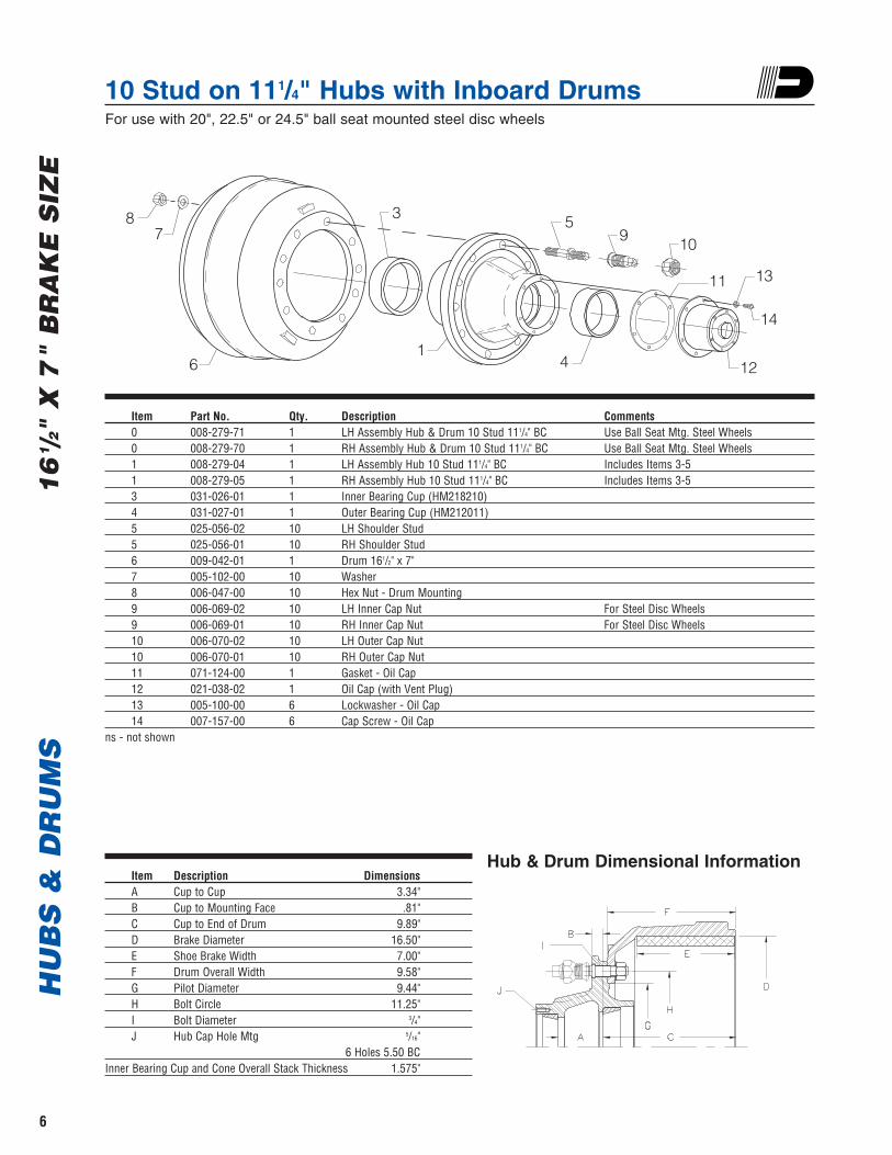
10 Stud on 111/4" Hubs with Inboard Drums For use with 20", 22.5" or 24.5" ball seat mounted steel disc wheels
HU
BS
& D
RU
MS
16
1 /2"
X 7
" B
RA
KE
SIZ
E
6
Item Part No. Qty. Description Comments0 008-279-71 1 LH Assembly Hub & Drum 10 Stud 111/4" BC Use Ball Seat Mtg. Steel Wheels0 008-279-70 1 RH Assembly Hub & Drum 10 Stud 111/4" BC Use Ball Seat Mtg. Steel Wheels1 008-279-04 1 LH Assembly Hub 10 Stud 111/4" BC Includes Items 3-51 008-279-05 1 RH Assembly Hub 10 Stud 111/4" BC Includes Items 3-53 031-026-01 1 Inner Bearing Cup (HM218210)4 031-027-01 1 Outer Bearing Cup (HM212011)5 025-056-02 10 LH Shoulder Stud5 025-056-01 10 RH Shoulder Stud6 009-042-01 1 Drum 161/2" x 7"7 005-102-00 10 Washer8 006-047-00 10 Hex Nut - Drum Mounting9 006-069-02 10 LH Inner Cap Nut For Steel Disc Wheels9 006-069-01 10 RH Inner Cap Nut For Steel Disc Wheels10 006-070-02 10 LH Outer Cap Nut10 006-070-01 10 RH Outer Cap Nut11 071-124-00 1 Gasket - Oil Cap12 021-038-02 1 Oil Cap (with Vent Plug)13 005-100-00 6 Lockwasher - Oil Cap14 007-157-00 6 Cap Screw - Oil Cap
ns - not shown
Item Description DimensionsA Cup to Cup 3.34"B Cup to Mounting Face .81"C Cup to End of Drum 9.89"D Brake Diameter 16.50"E Shoe Brake Width 7.00"F Drum Overall Width 9.58"G Pilot Diameter 9.44"H Bolt Circle 11.25"I Bolt Diameter 3/4"J Hub Cap Hole Mtg 5/16"
6 Holes 5.50 BCInner Bearing Cup and Cone Overall Stack Thickness 1.575"
Hub & Drum Dimensional Information
87
6
3
1
59 10
11
4
13
14
12
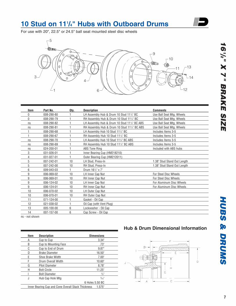
10 Stud on 111/4" Hubs with Outboard Drums For use with 20", 22.5" or 24.5" ball seat mounted steel disc wheels
HU
BS
& D
RU
MS
16
1/2" X 7
" BR
AK
E S
IZE
7
Item Part No. Qty. Description Comments0 008-290-80 1 LH Assembly Hub & Drum 10 Stud 111/4" BC Use Ball Seat Mtg. Wheels0 008-290-79 1 RH Assembly Hub & Drum 10 Stud 111/4" BC Use Ball Seat Mtg. Wheelsns 008-290-82 1 LH Assembly Hub & Drum 10 Stud 111/4" BC ABS Use Ball Seat Mtg. Wheelsns 008-290-81 1 RH Assembly Hub & Drum 10 Stud 111/4" BC ABS Use Ball Seat Mtg. Wheels1 008-290-68 1 LH Assembly Hub 10 Stud 111/4" BC Includes Items 3-51 008-290-67 1 RH Assembly Hub 10 Stud 111/4" BC Includes Items 3-5ns 008-290-70 1 LH Assembly Hub 10 Stud 111/4" BC ABS Includes Items 3-5ns 008-290-69 1 RH Assembly Hub 10 Stud 111/4" BC ABS Includes Items 3-5ns 024-200-01 1 ABS Tone Ring Included with ABS hubs3 031-026-01 1 Inner Bearing Cup (HM218210)4 031-027-01 1 Outer Bearing Cup (HM212011)5 007-242-01 10 LH Stud, Press-In 1.38" Stud Stand Out Length5 007-242-00 10 RH Stud, Press-In 1.38" Stud Stand Out Length6 009-043-03 1 Drum 161/2" x 7"9 006-069-02 10 LH Inner Cap Nut For Steel Disc Wheels9 006-069-01 10 RH Inner Cap Nut For Steel Disc Wheels9 006-124-02 10 LH Inner Cap Nut For Aluminum Disc Wheels9 006-124-01 10 RH Inner Cap Nut For Aluminum Disc Wheels10 006-070-02 10 LH Outer Cap Nut10 006-070-01 10 RH Outer Cap Nut11 071-124-00 1 Gasket - Oil Cap12 021-038-02 1 Oil Cap (with Vent Plug)13 005-100-00 6 Lockwasher - Oil Cap14 007-157-00 6 Cap Screw - Oil Cap
ns - not shown
Item Description DimensionsA Cup to Cup 3.34"B Cup to Mounting Face .73"C Cup to End of Drum 9.87"D Brake Diameter 16.50"E Shoe Brake Width 7.00"F Drum Overall Width 10.60"G Pilot Diameter 8.78"H Bolt Circle 11.25"I Bolt Diameter 3/4" J Hub Cap Hole Mtg 5/16"
6 Holes 5.50 BCInner Bearing Cup and Cone Overall Stack Thickness 1.575"
Hub & Drum Dimensional Information
3
5
1
4
6
910
11 13
14
12
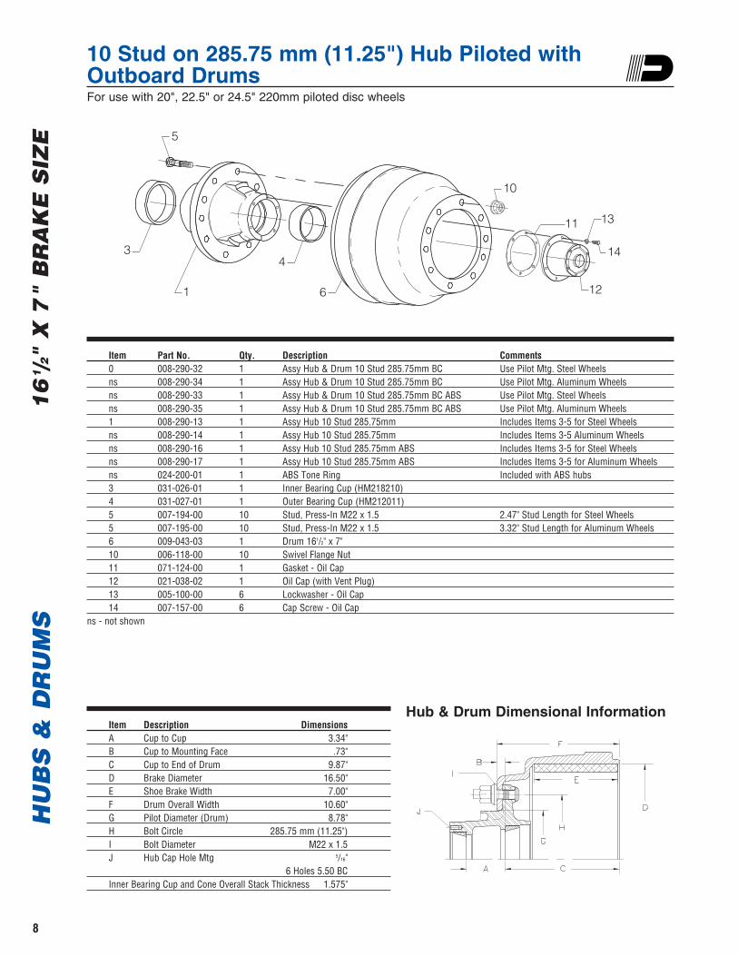
10 Stud on 285.75 mm (11.25") Hub Piloted with Outboard Drums For use with 20", 22.5" or 24.5" 220mm piloted disc wheels
HU
BS
& D
RU
MS
16
1 /2"
X 7
" B
RA
KE
SIZ
E
8
Item Part No. Qty. Description Comments0 008-290-32 1 Assy Hub & Drum 10 Stud 285.75mm BC Use Pilot Mtg. Steel Wheelsns 008-290-34 1 Assy Hub & Drum 10 Stud 285.75mm BC Use Pilot Mtg. Aluminum Wheelsns 008-290-33 1 Assy Hub & Drum 10 Stud 285.75mm BC ABS Use Pilot Mtg. Steel Wheelsns 008-290-35 1 Assy Hub & Drum 10 Stud 285.75mm BC ABS Use Pilot Mtg. Aluminum Wheels1 008-290-13 1 Assy Hub 10 Stud 285.75mm Includes Items 3-5 for Steel Wheelsns 008-290-14 1 Assy Hub 10 Stud 285.75mm Includes Items 3-5 Aluminum Wheelsns 008-290-16 1 Assy Hub 10 Stud 285.75mm ABS Includes Items 3-5 for Steel Wheelsns 008-290-17 1 Assy Hub 10 Stud 285.75mm ABS Includes Items 3-5 for Aluminum Wheelsns 024-200-01 1 ABS Tone Ring Included with ABS hubs3 031-026-01 1 Inner Bearing Cup (HM218210)4 031-027-01 1 Outer Bearing Cup (HM212011)5 007-194-00 10 Stud, Press-In M22 x 1.5 2.47" Stud Length for Steel Wheels5 007-195-00 10 Stud, Press-In M22 x 1.5 3.32" Stud Length for Aluminum Wheels6 009-043-03 1 Drum 161/2" x 7"10 006-118-00 10 Swivel Flange Nut11 071-124-00 1 Gasket - Oil Cap12 021-038-02 1 Oil Cap (with Vent Plug)13 005-100-00 6 Lockwasher - Oil Cap14 007-157-00 6 Cap Screw - Oil Cap
ns - not shown
Item Description DimensionsA Cup to Cup 3.34"B Cup to Mounting Face .73"C Cup to End of Drum 9.87"D Brake Diameter 16.50"E Shoe Brake Width 7.00"F Drum Overall Width 10.60"G Pilot Diameter (Drum) 8.78"H Bolt Circle 285.75 mm (11.25")I Bolt Diameter M22 x 1.5J Hub Cap Hole Mtg 5/16"
6 Holes 5.50 BCInner Bearing Cup and Cone Overall Stack Thickness 1.575"
Hub & Drum Dimensional Information
3
5
1
4
6
10
11 13
14
12

5–Spoke Cast Wheels For use with 20" or 22.5" demountable rims
HU
BS
& D
RU
MS
16
1/2" X 7
" BR
AK
E S
IZE
9
11111212 1313
1414
Item Part No. Qty. Description008-267-71 1 Wheel & Drum Assembly - Gunite 5763-1008-267-72 1 Wheel & Drum Assembly - Webb 75209-GCA 008-267-76 1 Wheel & Drum Assembly - KIC 001-75207H008-267-74 1 ABS Wheel & Drum Assembly - Gunite 5763-2008-267-77 1 ABS Wheel & Drum Assembly - KIC 001-75207TH
11 071-124-00 1 Gasket - Oil Cap12 021-038-02 1 Oil Cap (with Vent Plug)13 005-100-00 6 Lockwasher - Oil Cap14 007-157-00 6 Cap Screw - Oil Cap
Item Description DimensionsA Cup to Cup 3.34"B Cup to Centerline Track 1.36" (w/4.00" spacer)C Cup to End of Drum 9.90"D Brake Diameter 16.50"E Shoe Brake Width 7.00"F Drum Overall Width 8.38"G Pilot Diameter 9.44"H Bolt Circle 11.00"I Bolt Diameter 5/8"J Hub Cap Hole Mtg 5/16"
6 Holes 5.50 BCK Spacer 20" x 4"Inner Bearing Cup and Cone Overall Stack Thickness 1.575"
Dimensions listed are referenced for Webb part only. Other cast wheel suppliers’ dimensions may be slightly different. Check with supplier.
Wheel and Drum Assembly
Hub & Drum Dimensional Information
Hubs & Drums; Wheels & DrumsH
UB
S &
DR
UM
SC
RO
SS
RE
FE
RE
NC
E
10
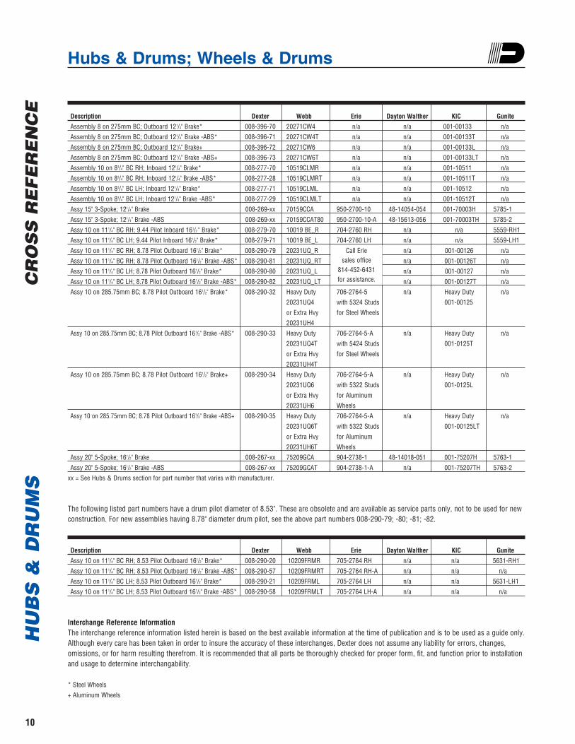
Description Dexter Webb Erie Dayton Walther KIC GuniteAssembly 8 on 275mm BC; Outboard 121/4" Brake* 008-396-70 20271CW4 n/a n/a 001-00133 n/aAssembly 8 on 275mm BC; Outboard 121/4" Brake -ABS* 008-396-71 20271CW4T n/a n/a 001-00133T n/aAssembly 8 on 275mm BC; Outboard 121/4" Brake+ 008-396-72 20271CW6 n/a n/a 001-00133L n/aAssembly 8 on 275mm BC; Outboard 121/4" Brake -ABS+ 008-396-73 20271CW6T n/a n/a 001-00133LT n/aAssembly 10 on 83/4" BC RH; Inboard 121/4" Brake* 008-277-70 10519CLMR n/a n/a 001-10511 n/aAssembly 10 on 83/4" BC RH; Inboard 121/4" Brake -ABS* 008-277-28 10519CLMRT n/a n/a 001-10511T n/aAssembly 10 on 83/4" BC LH; Inboard 121/4" Brake* 008-277-71 10519CLML n/a n/a 001-10512 n/aAssembly 10 on 83/4" BC LH; Inboard 121/4" Brake -ABS* 008-277-29 10519CLMLT n/a n/a 001-10512T n/aAssy 15" 3-Spoke; 121/4" Brake 008-269-xx 70159CCA 950-2700-10 48-14054-054 001-70003H 5785-1Assy 15" 3-Spoke; 121/4" Brake -ABS 008-269-xx 70159CCAT80 950-2700-10-A 48-15613-056 001-70003TH 5785-2Assy 10 on 111/4" BC RH; 9.44 Pilot Inboard 161/2 " Brake* 008-279-70 10019 BE_R 704-2760 RH n/a n/a 5559-RH1Assy 10 on 111/4" BC LH; 9.44 Pilot Inboard 161/2" Brake* 008-279-71 10019 BE_L 704-2760 LH n/a n/a 5559-LH1Assy 10 on 111/4" BC RH; 8.78 Pilot Outboard 161/2" Brake* 008-290-79 20231UQ_R n/a 001-00126 n/aAssy 10 on 111/4" BC RH; 8.78 Pilot Outboard 161/2" Brake -ABS* 008-290-81 20231UQ_RT n/a 001-00126T n/aAssy 10 on 111/4" BC LH; 8.78 Pilot Outboard 161/2" Brake* 008-290-80 20231UQ_L n/a 001-00127 n/aAssy 10 on 111/4" BC LH; 8.78 Pilot Outboard 161/2" Brake -ABS* 008-290-82 20231UQ_LT n/a 001-00127T n/aAssy 10 on 285.75mm BC; 8.78 Pilot Outboard 161/2" Brake* 008-290-32 Heavy Duty 706-2764-5 n/a Heavy Duty n/a
20231UQ4 with 5324 Studs 001-00125or Extra Hvy for Steel Wheels20231UH4
Assy 10 on 285.75mm BC; 8.78 Pilot Outboard 161/2" Brake -ABS* 008-290-33 Heavy Duty 706-2764-5-A n/a Heavy Duty n/a20231UQ4T with 5424 Studs 001-0125Tor Extra Hvy for Steel Wheels20231UH4T
Assy 10 on 285.75mm BC; 8.78 Pilot Outboard 161/2" Brake+ 008-290-34 Heavy Duty 706-2764-5-A n/a Heavy Duty n/a20231UQ6 with 5322 Studs 001-0125Lor Extra Hvy for Aluminum20231UH6 Wheels
Assy 10 on 285.75mm BC; 8.78 Pilot Outboard 161/2" Brake -ABS+ 008-290-35 Heavy Duty 706-2764-5-A n/a Heavy Duty n/a20231UQ6T with 5322 Studs 001-00125LTor Extra Hvy for Aluminum20231UH6T Wheels
Assy 20" 5-Spoke; 161/2" Brake 008-267-xx 75209GCA 904-2738-1 48-14018-051 001-75207H 5763-1Assy 20" 5-Spoke; 161/2" Brake -ABS 008-267-xx 75209GCAT 904-2738-1-A n/a 001-75207TH 5763-2
xx = See Hubs & Drums section for part number that varies with manufacturer.
The following listed part numbers have a drum pilot diameter of 8.53". These are obsolete and are available as service parts only, not to be used for newconstruction. For new assemblies having 8.78" diameter drum pilot, see the above part numbers 008-290-79; -80; -81; -82.
Description Dexter Webb Erie Dayton Walther KIC GuniteAssy 10 on 111/4" BC RH; 8.53 Pilot Outboard 161/2" Brake* 008-290-20 10209FRMR 705-2764 RH n/a n/a 5631-RH1Assy 10 on 111/4" BC RH; 8.53 Pilot Outboard 161/2" Brake -ABS* 008-290-57 10209FRMRT 705-2764 RH-A n/a n/a n/aAssy 10 on 111/4" BC LH; 8.53 Pilot Outboard 161/2" Brake* 008-290-21 10209FRML 705-2764 LH n/a n/a 5631-LH1Assy 10 on 111/4" BC LH; 8.53 Pilot Outboard 161/2" Brake -ABS* 008-290-58 10209FRMLT 705-2764 LH-A n/a n/a n/a
Interchange Reference InformationThe interchange reference information listed herein is based on the best available information at the time of publication and is to be used as a guide only.Although every care has been taken in order to insure the accuracy of these interchanges, Dexter does not assume any liability for errors, changes,omissions, or for harm resulting therefrom. It is recommended that all parts be thoroughly checked for proper form, fit, and function prior to installationand usage to determine interchangability.
* Steel Wheels+ Aluminum Wheels
Call Erie sales office
814-452-6431 for assistance.
Bearings, Seals, and CapsH
UB
S &
DR
UM
SC
RO
SS
RE
FE
RE
NC
E
11
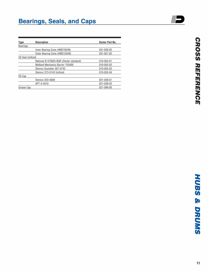
Type Description Dexter Part No.Bearings
Inner Bearing Cone (HM218248) 031-026-02Outer Bearing Cone (HM212049) 031-027-02
Oil Seal UnitizedNational B-370025-BGR (Dexter standard) 010-055-01Midland Mechanics Barrier 755400 010-055-02Stemco Guardian 307-0743 010-055-03Stemco 373-0143 Unitized 010-055-04
Oil CapStemco 343-4009 021-038-01APT A-4010 021-038-02
Grease Cap 021-046-00
Anti-Lock Braking Systems (ABS)H
UB
S &
DR
UM
S
12
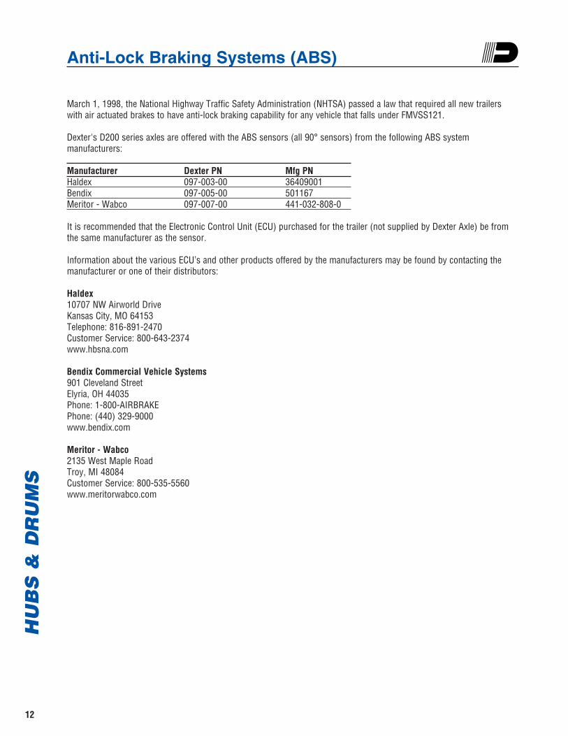
March 1, 1998, the National Highway Traffic Safety Administration (NHTSA) passed a law that required all new trailerswith air actuated brakes to have anti-lock braking capability for any vehicle that falls under FMVSS121.
Dexter's D200 series axles are offered with the ABS sensors (all 90° sensors) from the following ABS system manufacturers:
Manufacturer Dexter PN Mfg PNHaldex 097-003-00 36409001Bendix 097-005-00 501167Meritor - Wabco 097-007-00 441-032-808-0
It is recommended that the Electronic Control Unit (ECU) purchased for the trailer (not supplied by Dexter Axle) be fromthe same manufacturer as the sensor.
Information about the various ECU’s and other products offered by the manufacturers may be found by contacting themanufacturer or one of their distributors:
Haldex 10707 NW Airworld DriveKansas City, MO 64153Telephone: 816-891-2470Customer Service: 800-643-2374www.hbsna.com
Bendix Commercial Vehicle Systems901 Cleveland StreetElyria, OH 44035Phone: 1-800-AIRBRAKEPhone: (440) 329-9000www.bendix.com
Meritor - Wabco2135 West Maple RoadTroy, MI 48084Customer Service: 800-535-5560www.meritorwabco.com
Tires & WheelsT
IRE
S &
WH
EE
LS
CL
EA
RA
NC
ES
AN
D D
IME
NS
ION
S
13
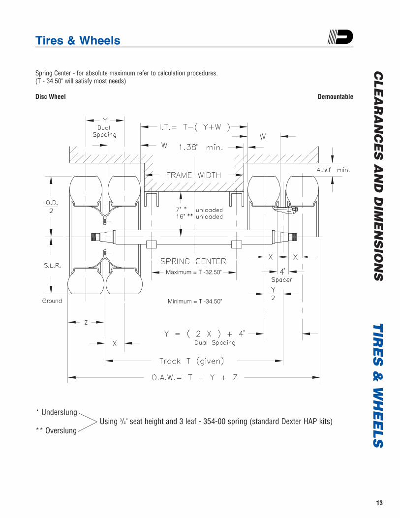
Spring Center - for absolute maximum refer to calculation procedures. (T - 34.50" will satisfy most needs)
Disc Wheel Demountable
* UnderslungUsing 3/4" seat height and 3 leaf - 354-00 spring (standard Dexter HAP kits)
** Overslung
Maximum = T -32.50"
Minimum = T -34.50"
"
"
"
"
Ground
""

TiresT
IRE
S &
WH
EE
LS
14
Brake Size
121/4"
121/4"
121/4"
121/4"
121/4"
161/2"
161/2"
161/2"
161/2"
161/2"
161/2"
Tire Size(Load Range)
10R17.5 (H)
215/75R17.5 (H)
235/75R17.5 (H)
245/70R19.5 (G)
265/70R19.5 (G)
255/70R22.5 (H)
295/75R22.5 (G)
11R22.5 (G)
11R22.5 (H)
11R24.5 (G)
11R24.5 (H)
DesignRim
Width
6.75HC
6.75HC
6.75HC
6.75
6.75
7.50
8.25
8.25
8.25
8.25
8.25
**Dual TireCapacityper Tire(lbs.)
4410
4540
5675
4375
5070
5070
5675
5750
5800
6000
6170
Max.InflationP.S.I.
115
125
125
100
120
115
100
105
110
105
110
O.D.*
33.7
30.6
31.8
33.0
34.0
36.6
40.2
41.5
41.5
43.5
43.5
Tire Width
W
9.4
8.4
9.2
10.2
10.3
9.8
11.2
10.8
10.8
10.8
10.8
LoadedSectionWidth
Z
10.4
9.3
10.1
11.0
11.2
10.6
12.2
11.9
11.9
11.9
11.9
S.L.R.*
15.6
14
14.5
15.3
15.9
17.1
18.8
19.4
19.4
20.4
20.4
Min. Dual
Spacing
10.9
9.6
10.3
11.0
11.6
11.3
11.2
12.5
12.5
12.5
12.5
* Dimensions shown may vary slightly from manufacturer to manufacturer** Dual Rating
AP
PL
ICA
TIO
N I
NF
OR
MA
TIO
N
Wheels & RimsT
IRE
S &
WH
EE
LS
15
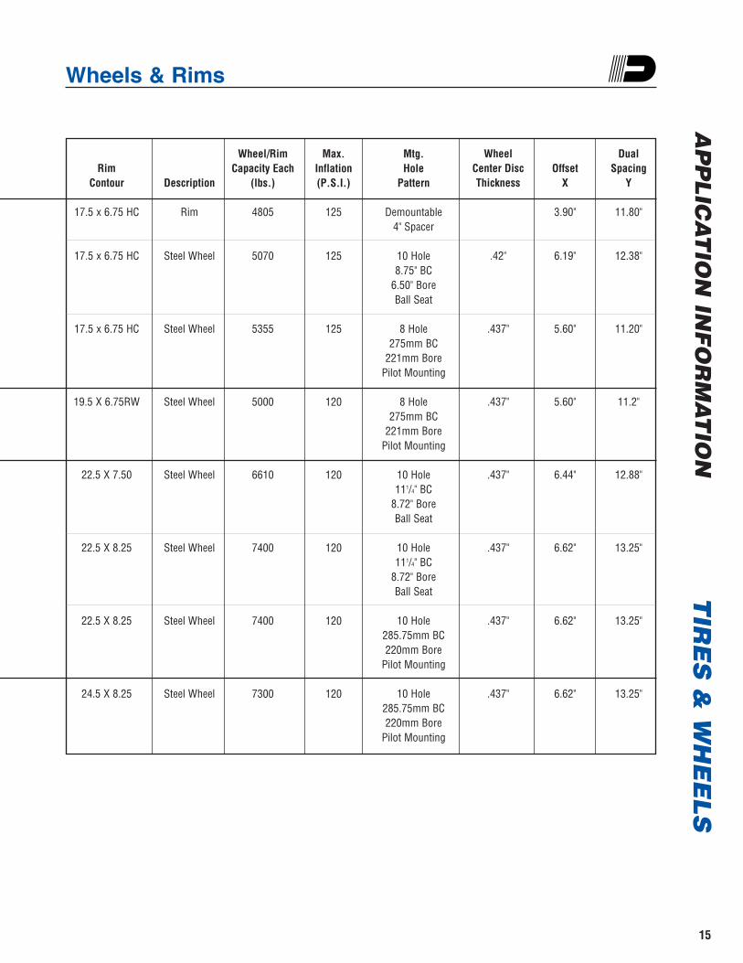
Rim Contour
17.5 x 6.75 HC
17.5 x 6.75 HC
17.5 x 6.75 HC
19.5 X 6.75RW
22.5 X 7.50
22.5 X 8.25
22.5 X 8.25
24.5 X 8.25
Description
Rim
Steel Wheel
Steel Wheel
Steel Wheel
Steel Wheel
Steel Wheel
Steel Wheel
Steel Wheel
Wheel/RimCapacity Each
(lbs.)
4805
5070
5355
5000
6610
7400
7400
7300
Max.Inflation(P.S.I.)
125
125
125
120
120
120
120
120
Mtg. Hole
Pattern
Demountable 4" Spacer
10 Hole 8.75" BC
6.50" Bore Ball Seat
8 Hole275mm BC
221mm BorePilot Mounting
8 Hole275mm BC
221mm BorePilot Mounting
10 Hole111/4" BC
8.72" BoreBall Seat
10 Hole111/4" BC
8.72" BoreBall Seat
10 Hole285.75mm BC220mm Bore
Pilot Mounting
10 Hole285.75mm BC220mm Bore
Pilot Mounting
Wheel Center DiscThickness
.42"
.437"
.437"
.437"
.437"
.437"
.437"
Offset X
3.90"
6.19"
5.60"
5.60"
6.44"
6.62"
6.62"
6.62"
DualSpacing
Y
11.80"
12.38"
11.20"
11.2"
12.88"
13.25"
13.25"
13.25"
AP
PL
ICA
TIO
N IN
FO
RM
AT
ION
Determining Maximum Spring Centers for 22.5K - 27.5K Axles
TIR
ES
& W
HE
EL
SA
PP
LIC
AT
ION
IN
FO
RM
AT
ION
16
1. Typical over-the-road 96" wide semi-trailers with leafspring suspensions are equipped with axles having71" or 711/2" axle track and either 38" or 39" springcenters. 102" wide trailers use axles having 77" or771/2" axle track and either 44" or 45" spring centers.
2. Axle track should be the widest possible with theoverall width of the outer dual tires not exceeding themaximum trailer width of either 96" or 102" asspecified by law. Verify with State and Federal lawsfor the type of roads the trailer is traveling.
3. Spring centers should be placed as wide as possibleto aid in resisting trailer rolling movement - side-to-side sway. Maximum spring center isgoverned by either the distance between drums orthe distance between the inner dual tires of a givenaxle. Spring centers less than the minimum specifiedwill reduce axle carrying capacity.
4. Begin by selecting appropriate dual tire capacity andrim or wheel capacity to adequately haul the load forwhich the trailer was designed.
Factor 1 - Distance between drums
A. Determine the hub group required to mate withthe tires, rims or wheels previously selected.
B. From the hub group section of this catalog, locatethe proper hub & drum or wheel & drum.
C. For Demountable Rims. Obtain the B and Cdimensions for your selected hub group in thiscatalog, add them together, then multiply by 2.Subtract this number from your track dimensionto obtain the dimension between drums.
D. For Disc Wheels. Obtain the B and C dimensionsfor your selected hub group in this catalog. Next,determine the wheel’s disc thickness at themounting area. Add these three figures together,then multiply by 2. Subtract this number fromyour track dimension to obtain the dimensionbetween drums.
Factor 2 - Distance between inner tires
5. Obtain the tire width dimension for the tirespreviously selected. Dimensions shown in thiscatalog may vary from manufacturer tomanufacturer. Check your tire manufacturer’s latesttire catalog to be sure of the dimensions.
A. For Demountable Rims. From the previouspages, obtain the W dimension (width of yourselected tire) and the Y dimension (dual rimspacing of appropriate rims for your selected tire)and add them together. Subtract this numberfrom your track dimension to obtain thedimension between the inner dual tire set.
B. For Disc Wheels. From the previous pages,obtain the W dimension (width of your selectedtire) and the Y dimension (dual wheel spacing ofappropriate wheels for your selected tire) and addthem together. Subtract this number from yourtrack dimension to obtain the dimension betweenthe inner dual tire set.
6. Compare these two calculated numbers — Factor 1and Factor 2 — and select the smallest (narrowest)of the two.
7. Subtract 2.75 from the above selected smallestnumber. This should be your outside to outsidewidest frame width for your given track. Theminimum frame clearance per side is 1.375, then ismultiplied by 2 to get 2.75.
8. Determine the width of your suspension systemhangers, typically 6.00 inches for H-9700 Hutchsuspension. If other than Hutch H-9700 are used,determine the location of your selected suspensionsystem’s hangers and where they are to bepositioned laterally on the trailer frame member.Consult the manufacturer of your suspension systemif the location is not detailed in their catalog.Determine the distance from frame width tocenterline of suspension attachment to the axle beam tube relative to this hanger position.
9. Subtract this number from outside frame width toobtain the maximum spring center allowed.
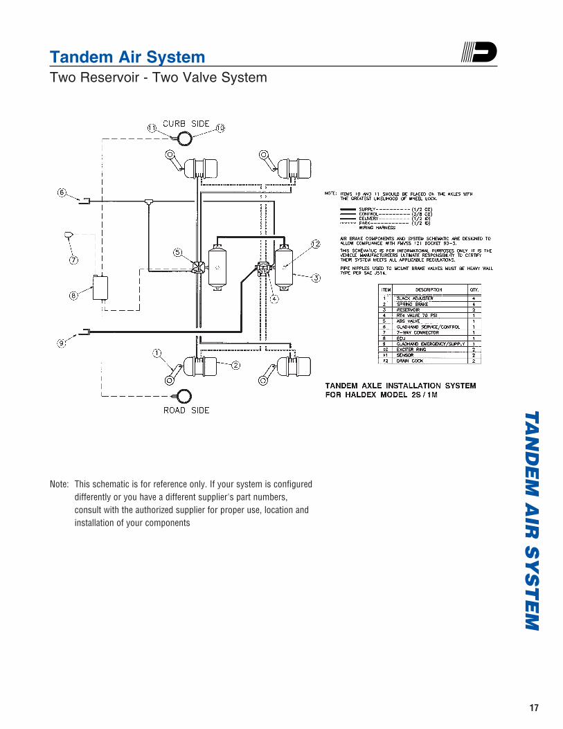
Note: This schematic is for reference only. If your system is configureddifferently or you have a different supplier's part numbers, consult with the authorized supplier for proper use, location andinstallation of your components
Tandem Air SystemTwo Reservoir - Two Valve System
TA
ND
EM
AIR
SY
ST
EM
17
AX
LE
/BR
AK
E C
OM
PO
NE
NT
S1
21/4 "
X 7
1/2 "
BR
AK
E S
IZE
18
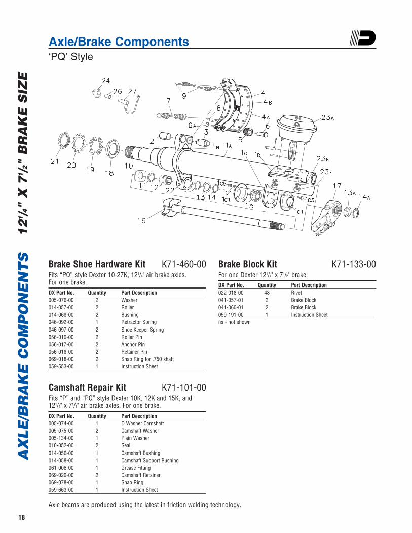
Axle/Brake Components ‘PQ’ Style
Brake Shoe Hardware Kit K71-460-00Fits “PQ” style Dexter 10-27K, 121/4" air brake axles.For one brake. DX Part No. Quantity Part Description 005-076-00 2 Washer014-057-00 2 Roller014-068-00 2 Bushing046-092-00 1 Retractor Spring046-097-00 2 Shoe Keeper Spring056-010-00 2 Roller Pin056-017-00 2 Anchor Pin 056-018-00 2 Retainer Pin 069-018-00 2 Snap Ring for .750 shaft059-553-00 1 Instruction Sheet
Camshaft Repair Kit K71-101-00Fits “P” and “PQ” style Dexter 10K, 12K and 15K, and 121/4" x 71/2" air brake axles. For one brake.DX Part No. Quantity Part Description 005-074-00 1 D Washer Camshaft005-075-00 2 Camshaft Washer005-134-00 1 Plain Washer010-052-00 2 Seal 014-056-00 1 Camshaft Bushing014-058-00 1 Camshaft Support Bushing061-006-00 1 Grease Fitting069-020-00 2 Camshaft Retainer069-078-00 1 Snap Ring059-663-00 1 Instruction Sheet
Brake Block Kit K71-133-00For one Dexter 121/4" x 71/2" brake.DX Part No. Quantity Part Description 022-018-00 48 Rivet041-057-01 2 Brake Block041-060-01 2 Brake Block059-191-00 1 Instruction Sheetns - not shown
Axle beams are produced using the latest in friction welding technology.
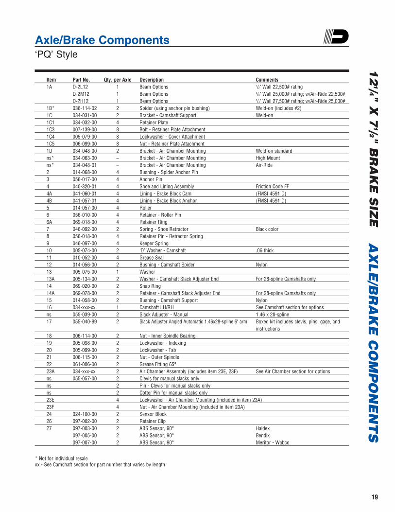
Axle/Brake Components ‘PQ’ Style
Item Part No. Qty. per Axle Description Comments1A D-2L12 1 Beam Options 1/2" Wall 22,500# rating
D-2M12 1 Beam Options 5/8" Wall 25,000# rating; w/Air-Ride 22,500#D-2H12 1 Beam Options 3/4" Wall 27,500# rating; w/Air-Ride 25,000#
1B* 036-114-02 2 Spider (using anchor pin bushing) Weld-on (includes #2)1C 034-031-00 2 Bracket - Camshaft Support Weld-on1C1 034-032-00 4 Retainer Plate1C3 007-139-00 8 Bolt - Retainer Plate Attachment 1C4 005-079-00 8 Lockwasher - Cover Attachment1C5 006-099-00 8 Nut - Retainer Plate Attachment1D 034-048-00 2 Bracket - Air Chamber Mounting Weld-on standardns* 034-063-00 – Bracket - Air Chamber Mounting High Mountns* 034-048-01 – Bracket - Air Chamber Mounting Air-Ride2 014-068-00 4 Bushing - Spider Anchor Pin3 056-017-00 4 Anchor Pin4 040-320-01 4 Shoe and Lining Assembly Friction Code FF4A 041-060-01 4 Lining - Brake Block Cam (FMSI 4591 D)4B 041-057-01 4 Lining - Brake Block Anchor (FMSI 4591 D)5 014-057-00 4 Roller6 056-010-00 4 Retainer - Roller Pin6A 069-018-00 4 Retainer Ring7 046-092-00 2 Spring - Shoe Retractor Black color8 056-018-00 4 Retainer Pin - Retractor Spring9 046-097-00 4 Keeper Spring10 005-074-00 2 ‘D’ Washer - Camshaft .06 thick11 010-052-00 4 Grease Seal12 014-056-00 2 Bushing - Camshaft Spider Nylon13 005-075-00 1 Washer13A 005-134-00 2 Washer - Camshaft Slack Adjuster End For 28-spline Camshafts only14 069-020-00 2 Snap Ring14A 069-078-00 2 Retainer - Camshaft Stack Adjuster End For 28-spline Camshafts only15 014-058-00 2 Bushing - Camshaft Support Nylon16 034-xxx-xx 1 Camshaft LH/RH See Camshaft section for optionsns 055-039-00 2 Slack Adjuster - Manual 1.46 x 28-spline17 055-040-99 2 Slack Adjuster Angled Automatic 1.46x28-spline 6" arm Boxed kit includes clevis, pins, gage, and
instructions18 006-114-00 2 Nut - Inner Spindle Bearing19 005-098-00 2 Lockwasher - Indexing20 005-099-00 2 Lockwasher - Tab21 006-115-00 2 Nut - Outer Spindle22 061-006-00 2 Grease Fitting 65°23A 034-xxx-xx 2 Air Chamber Assembly (includes item 23E, 23F) See Air Chamber section for optionsns 055-057-00 2 Clevis for manual slacks onlyns 2 Pin - Clevis for manual slacks onlyns 2 Cotter Pin for manual slacks only23E 4 Lockwasher - Air Chamber Mounting (included in item 23A)23F 4 Nut - Air Chamber Mounting (included in item 23A)24 024-100-00 2 Sensor Block26 097-002-00 2 Retainer Clip27 097-003-00 2 ABS Sensor, 90° Haldex
097-005-00 2 ABS Sensor, 90° Bendix097-007-00 2 ABS Sensor, 90° Meritor - Wabco
* Not for individual resalexx - See Camshaft section for part number that varies by length
AX
LE
/BR
AK
E C
OM
PO
NE
NT
S1
21/4" X
71/2" B
RA
KE
SIZ
E
19

AX
LE
/BR
AK
E C
OM
PO
NE
NT
S1
61/2 "
X 7
" B
RA
KE
SIZ
E
20
Axle/Brake Components‘Q’ Style
Brake Shoe Hardware Kit K71-136-00Fits all “Q” quick change Dexter 161/2" x 7" air brake axles.For one brake. DX Part No. Quantity Part Description 014-065-00 2 Roller014-068-00 2 Spider Bushing046-096-00 1 Retractor Spring 161/2" Brake-orange046-097-00 2 Keeper Spring056-017-00 2 Anchor Pin056-018-00 2 Spring Retainer071-122-00 2 Roller Retainer059-554-00 1 Instruction Sheet
Camshaft Repair Kit K71-135-00Fits all “Q” quick change Dexter 161/2" x 7" air brake axles.For one brake.DX Part No. Quantity Part Description 005-096-00 1 Camshaft Washer005-097-00 2 Camshaft Washer005-134-00 1 Plain Washer010-052-00 2 Seal014-056-00 1 Camshaft Bushing014-058-00 1 Camshaft Support Bushing061-006-00 1 Grease Fitting069-020-00 2 Camshaft Retainer069-078-00 1 Snap Ring059-554-00 1 Instruction Sheet
Brake Block Kit K71-138-00For one Dexter 161/2" x 7" air brake.DX Part No. Quantity Part Description 022-018-00 48 Rivet 041-058-01 2 Brake Block 041-059-01 2 Brake Block 059-191-00 1 Instruction Sheetns - not shown
Axle beams are produced using the latest in friction welding technology.

Axle/Brake Components ‘Q’ Style
Item Part No. Qty. per Axle Description Comments1A D-2L16 1 Beam Options 1/2" Wall 22,500# rating
D-2M16 1 Beam Options 5/8" Wall 25,000# rating; w/Air-Ride 22,500#D-2H16 1 Beam Options 3/4" Wall 27,500# rating; w/Air-Ride 25,000#
1B* 036-092-02 2 Spider Weld-on (includes #2)1C 034-047-00 2 Bracket - Camshaft Support Weld-on1C2 034-032-00 4 Retainer Plate 1C3 007-139-00 8 Bolt - Retainer Plate Attachment 1C4 005-079-00 8 Lockwasher - Cover Attachment 1C5 006-099-00 8 Nut - Retainer Plate Attachment 1D 034-048-00 2 Bracket - Air Chamber Mounting Weld-on standardns* 034-063-00 - Bracket - Air Chamber Mounting High Mount2 014-068-00 4 Bushing - Spider Anchor Pin3 056-017-00 4 Anchor Pin4 040-180-00 4 Shoe and Lining Assembly Friction Code FF4A 041-058-01 4 Lining - Brake Block Cam (FMSI 4515 D)4B 041-059-01 4 Lining - Brake Block Anchor (FMSI 4515 D)5 014-065-00 4 Roller6 071-122-00 4 Retainer - Roller7 046-096-00 2 Spring - Shoe Retractor Orange color8 056-018-00 4 Retainer Pin - Retractor Spring9 046-097-00 4 Spring - Shoe Keeper Orange color10 005-096-00 2 Washer - Camshaft .120 thick11 010-052-00 4 Grease Seal12 014-056-00 2 Bushing - Camshaft Spider Nylon13 005-097-00 2 Washer13A 005-134-00 2 Washer - Camshaft Slack Adjuster End For 28-spline Camshafts only14 069-020-00 2 Snap Ring14A 069-078-00 2 Retainer - Camshaft Slack Adjuster End For 28-spline Camshafts only15 014-058-00 2 Bushing - Camshaft Support Nylon16 034-xxx-xx 2 Camshaft LH/RH See Camshaft section for optionsns 055-039-00 2 Slack Adjuster - Manual 1.46 x 28-spline17 055-040-98 2 Slack Adjuster Straight Automatic 1.46x28-spline 6" arm Boxed kit uncludes clevis, pins, gage, and
instructions18 006-114-00 2 Nut - Inner Spindle Bearing19 005-098-00 2 Lockwasher - Indexing20 005-099-00 2 Lockwasher - Tab21 006-115-00 2 Nut - Outer Spindle22 061-006-00 2 Grease Fitting 65°23A 034-xxx-xx 2 Air Chamber Assembly (includes item 23E, 23F) See Air Chamber section for optionsns 005-057-00 2 Clevis for manual slacks onlyns 2 Pin - Clevis for manual slacks onlyns 2 Cotter Pin for manual slacks only23E 4 Lockwasher - Air Chamber Mounting (included in item 23A)23F 4 Nut - Air Chamber Mounting (included in item 23A)24 024-100-00 2 Sensor Block25 097-002-00 2 Retainer Clip26 097-003-00 2 ABS Sensor, 90° Haldex
097-005-00 2 ABS Sensor, 90° Bendix097-007-00 2 ABS Sensor, 90° Meritor - Wabco
* Not for individual resalexx - See Camshaft section for part number that varies by length
AX
LE
/BR
AK
E C
OM
PO
NE
NT
S1
61/2" X
7" B
RA
KE
SIZ
E
21
CA
MS
HA
FT
S1
21/4 "
X 7
1/2 "
BR
AK
E S
IZE
22
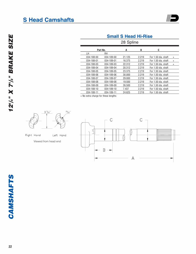
S Head Camshafts
Small S Head Hi-Rise28 Spline
Part No. A B CLH RH034-188-00 034-189-00 21.125 2.219 For 1.50 dia. shaft +034-188-01 034-189-01 16.375 2.219 For 1.50 dia. shaft +034-188-03 034-189-03 22.312 2.219 For 1.50 dia. shaft +034-188-04 034-189-04 20.312 2.219 For 1.50 dia. shaft 034-188-05 034-189-05 23.375 2.219 For 1.50 dia. shaft 034-188-06 034-189-06 30.000 2.219 For 1.50 dia. shaft 034-188-07 034-189-07 29.000 2.219 For 1.50 dia. shaft034-188-08 034-189-08 19.500 2.219 For 1.50 dia. shaft 034-188-09 034-189-09 26.500 2.219 For 1.50 dia. shaft 034-188-10 034-189-10 7.437 2.219 For 1.50 dia. shaft 034-188-11 034-189-11 24.625 2.219 For 1.50 dia. shaft
+ No extra charge for these lengths
3 3/32¨
Viewed from head end
29/32¨

S Head Camshafts
Large S Head Hi-Rise28 Spline
Part No. A B CLH RH034-192-00 034-193-00 16.625 2.219 For 1.50 dia. shaft +034-192-01 034-193-01 20.375 2.219 For 1.50 dia. shaft 034-192-02 034-193-02 30.000 2.219 For 1.50 dia. shaft 034-192-03 034-193-03 23.438 2.219 For 1.50 dia. shaft +034-192-04 034-193-04 26.500 2.219 For 1.50 dia. shaft 034-192-05 034-193-05 22.625 2.219 For 1.50 dia. shaft 034-192-06 034-193-06 19.500 2.219 For 1.50 dia. shaft 034-192-07 034-193-07 29.000 2.219 For 1.50 dia. shaft034-192-08 034-193-08 25.000 2.219 For 1.50 dia. shaft 034-192-09 034-193-09 28.000 2.219 For 1.50 dia. shaft 034-192-10 034-193-10 24.375 2.219 For 1.50 dia. shaft 034-192-11 034-193-11 7.438 2.219 For 1.50 dia. shaft
+ No extra charge for these lengths
4 1/4¨
Viewed from head end
1 3/16¨
CA
MS
HA
FT
S1
61/2" X
7" B
RA
KE
SIZ
E
23

AIR
CH
AM
BE
RS
24
Service Air Chambers
Part No. Size A B C D E F G Recommended Application
034-260-07 Type 20 5.62 7.00 1.25 5/8 - 11 5/8 -18 4.75 .50 121/4" Brake with Crewson Angled Automatic Slack
034-260-08 Type 20 6.38 7.00 1.25 5/8 - 11 5/8 -18 4.75 .50 121/4" Brake with Straight Manual Slack
034-059-01 Type 24 7.00 7.50 1.25 5/8 - 11 5/8 -18 4.75 .50 Optional 161/2" Brake with Crewson Angled Automatic
Slack
034-059-07 Type 24 5.62 7.50 1.25 5/8 - 11 5/8 -18 4.75 .50 121/4" Brake with Crewson Angled Automatic Slack
034-059-08 Type 24 6.38 7.50 1.25 5/8 - 11 5/8 -18 4.75 .50 121/4" Brake with Straight Manual Slack
034-057-01 Type 30 7.00 8.50 1.25 5/8 - 11 5/8 -18 4.75 .50 Standard 161/2" Brake
034-057-07 Type 30 5.62 8.50 1.25 5/8 - 11 5/8 -18 4.75 .50 121/4" Brake with Crewson Angled Automatic Slack
034-057-08 Type 30 6.38 8.50 1.25 5/8 - 11 5/8 -18 4.75 .50 121/4" Brake with Straight Manual Slack
Note: Clevis assembly NOT included with air chamber. See brake section for Clevis kits.
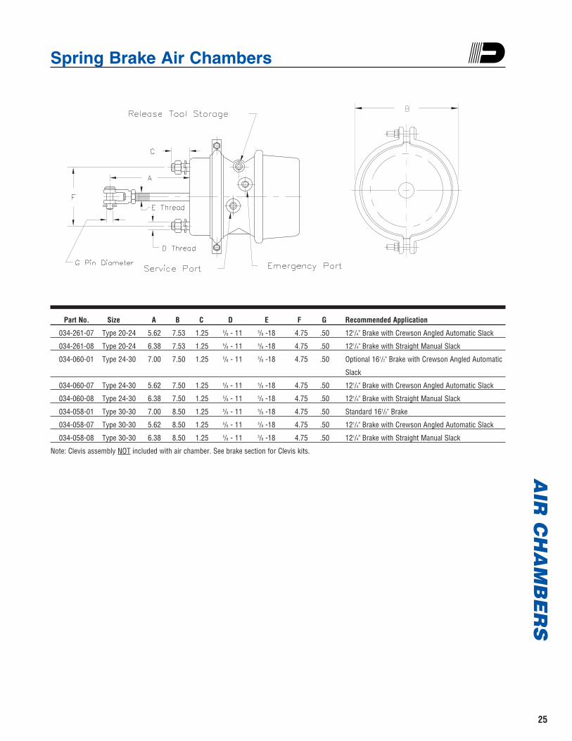
Spring Brake Air ChambersA
IR C
HA
MB
ER
S
25
Part No. Size A B C D E F G Recommended Application
034-261-07 Type 20-24 5.62 7.53 1.25 5/8 - 11 5/8 -18 4.75 .50 121/4" Brake with Crewson Angled Automatic Slack
034-261-08 Type 20-24 6.38 7.53 1.25 5/8 - 11 5/8 -18 4.75 .50 121/4" Brake with Straight Manual Slack
034-060-01 Type 24-30 7.00 7.50 1.25 5/8 - 11 5/8 -18 4.75 .50 Optional 161/2" Brake with Crewson Angled Automatic
Slack
034-060-07 Type 24-30 5.62 7.50 1.25 5/8 - 11 5/8 -18 4.75 .50 121/4" Brake with Crewson Angled Automatic Slack
034-060-08 Type 24-30 6.38 7.50 1.25 5/8 - 11 5/8 -18 4.75 .50 121/4" Brake with Straight Manual Slack
034-058-01 Type 30-30 7.00 8.50 1.25 5/8 - 11 5/8 -18 4.75 .50 Standard 161/2" Brake
034-058-07 Type 30-30 5.62 8.50 1.25 5/8 - 11 5/8 -18 4.75 .50 121/4" Brake with Crewson Angled Automatic Slack
034-058-08 Type 30-30 6.38 8.50 1.25 5/8 - 11 5/8 -18 4.75 .50 121/4" Brake with Straight Manual Slack
Note: Clevis assembly NOT included with air chamber. See brake section for Clevis kits.

Tandem Axle ConfigurationsOff-Road Applications
AIR
CH
AM
BE
RS
26
Note:1. Position of air chambers as shown results in optimum clearances.2. Use of equal length service lines is recommended.3. To assure welds are within approved neutral axis zone quadrants, maximum rotation of camshaft position is +6° up to
-6° down from 0° neutral axis.
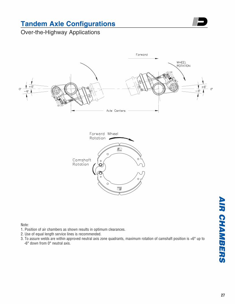
Tandem Axle ConfigurationsOver-the-Highway Applications
AIR
CH
AM
BE
RS
27
Note:1. Position of air chambers as shown results in optimum clearances.2. Use of equal length service lines is recommended.3. To assure welds are within approved neutral axis zone quadrants, maximum rotation of camshaft position is +6° up to
-6° down from 0° neutral axis.
28
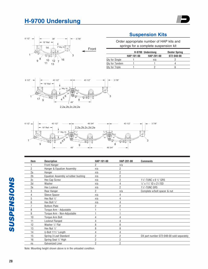
H-9700 UnderslungS
US
PE
NS
ION
S
Item Description HAP-101-00 HAP-201-00 Comments1 Front Hanger 2 n/a2 Hanger & Equalizer Assembly n/a 22a Hanger n/a 22b Equalizer Assembly w/rubber bushing n/a 22c Hex Cap Screw n/a 2 11/8"-7UNC x 6 5/8" GR52d Washer n/a 4 1/8" x 11/4" ID x 21/4"OD2e Hex Locknut n/a 2 11/8"-7UNC GR53 Rear Hanger 2 n/a Complete w/bolt spacer & nut4 Sleeve Spacer n/a 45 Hex Nut 5/8" n/a 46 Hex Bolt 5/8" n/a 47 Bottom Plate 2 28 Torque Arm - Adjustable 1 19 Torque Arm - Non-Adjustable 1 110 Torque Arm Bolt 4 411 Locknut Flanged 4 412 Washer 7/8" Flat 8 813 Hex Nut 7/8" 8 814 U-Bolt 113/4" Length 4 415 Spring 3-Leaf Standard 2 2 DX part number 072-048-00 sold separately16 Spring Seat 3/4" High 2 2ns Galvanized Liner 2 2
6 1/2” 38”
7”
3
712
14
16
13119
8
1
10
3 7/8”
Mtg. Ht.
19” Ref.
6 1/2” 43 1/2”
49”
7” Mtg. Ht.
43 1/2” 3 7/8”
117 9 4
56
83
2,2a,2b,2c,2d,2e
19” Ref.
6 1/2” 43 1/2” 49 3/4” 43 1/2”
19” Ref.
7” Mtg. Ht.
3 7/8”
19 9
654 8
3
2,2a,2b,2c,2d,2e
49” 49 3/4”
Note: Mounting height shown above is in the unloaded condition.
Suspension KitsOrder appropriate number of HAP kits and
springs for a complete suspension kit
H-9700 Underslung Dexter SpringHAP-101-00 HAP-201-00 072-048-00
Qty for Single 1 n/a 2Qty for Tandem 1 1 4Qty for Triple 1 2 6
Front
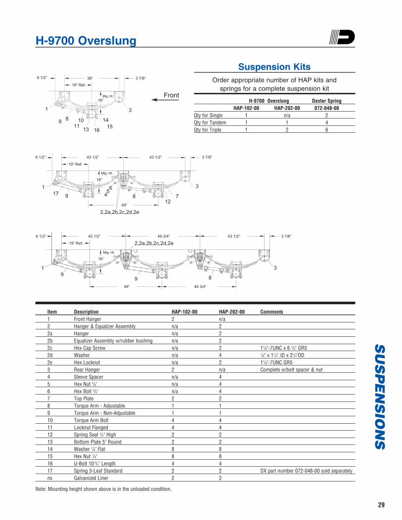
H-9700 OverslungS
US
PE
NS
ION
S
Item Description HAP-102-00 HAP-202-00 Comments1 Front Hanger 2 n/a2 Hanger & Equalizer Assembly n/a 22a Hanger n/a 22b Equalizer Assembly w/rubber bushing n/a 22c Hex Cap Screw n/a 2 11/8"-7UNC x 6 5/8" GR52d Washer n/a 4 1/8" x 11/4" ID x 21/4"OD2e Hex Locknut n/a 2 11/8"-7UNC GR53 Rear Hanger 2 n/a Complete w/bolt spacer & nut4 Sleeve Spacer n/a 45 Hex Nut 5/8" n/a 46 Hex Bolt 5/8" n/a 47 Top Plate 2 28 Torque Arm - Adjustable 1 19 Torque Arm - Non-Adjustable 1 110 Torque Arm Bolt 4 411 Locknut Flanged 4 412 Spring Seat 3/4" High 2 213 Bottom Plate 5" Round 2 214 Washer 7/8" Flat 8 815 Hex Nut 7/8" 8 816 U-Bolt 10 3/4" Length 4 417 Spring 3-Leaf Standard 2 2 DX part number 072-048-00 sold separatelyns Galvanized Liner 2 2
6 1/2” 38”
16”
3
1514
161311
9 8
1
10
3 7/8”
Mtg. Ht.
19” Ref.
6 1/2” 43 1/2”
49”
16”
Mtg. Ht.
43 1/2” 3 7/8”
117 9 4
56
812
7
3
2,2a,2b,2c,2d,2e
19” Ref.
6 1/2” 43 1/2” 49 3/4” 43 1/2”
19” Ref.
16”
Mtg. Ht.
3 7/8”
19
9 8
3
2,2a,2b,2c,2d,2e
49” 49 3/4”
Note: Mounting height shown above is in the unloaded condition.
29
Suspension KitsOrder appropriate number of HAP kits and
springs for a complete suspension kit
H-9700 Overslung Dexter SpringHAP-102-00 HAP-202-00 072-048-00
Qty for Single 1 n/a 2Qty for Tandem 1 1 4Qty for Triple 1 2 6
Front

Dexter Axle Limited Warranty
30
WHAT PRODUCTS ARE COVERED All Dexter trailer axles, suspensions, and brake control systemsexcluding Dexter 6000 series Manufactured Housing Axles.
LIMITED 2 YEAR WARRANTYDexter Axle warrants to the original purchaser that its axles,suspension systems, and E/H hydraulic brake actuators shall befree from defects in material and workmanship for a period oftwo (2) years from the date of first sale of the trailerincorporating such components.
LIMITED 5 YEAR WARRANTYDexter Axle warrants to the original purchaser that itsNev-R-Lube™ bearings and the suspension components only ofits Torflex® Axles shall be free from defects in material andworkmanship for a period of five (5) years from the date of firstsale of the trailer incorporating such components.
LIMITED 7 YEAR WARRANTYDexter Axle warrants to the original purchaser that its PredatorSeries™ electric brake controllers shall be free from defects inmaterial and workmanship for a period of seven (7) years fromthe date of purchase.
EXCLUSIVE REMEDY Dexter Axle will, at its option, repair or replace the affectedcomponents of any defective axle, repair or replace the entiredefective axle, or refund the then-current list price of the axle. Inall cases, a reasonable time period must be allowed for warrantyrepairs to be completed. Allowance will only be made forinstallation costs specifically approved by Dexter Axle.
WHAT YOU MUST DO In order to make a claim under these warranties:1. You must be the original purchaser of the vehicle in which
the Spring Suspension Axles or Torflex® Axles wereoriginally installed.
2. You must promptly notify us within the warranty period ofany defect, and provide us with the axle serial number andany substantiation which may include, but is not limited to,the return of part(s) that we may reasonably request.
3. The axles or suspensions must have been installed andmaintained in accordance with good industry practice andany specific Dexter Axle recommendations, including thosespecified in Dexter Axle’s publication “Operation,Maintenance Service Manual.”
EXCLUSIONS These warranties do not extend to or do not cover defectscaused by: 1. The connecting of brake wiring to the trailer wiring or
trailer wiring to the towing vehicle wiring. 2. The attachment of the running gear to the frame.3. Hub imbalance, or any damage caused thereby. 4. Parts not supplied by Dexter Axle. 5. Any damage whatever caused by or related to any
alteration of the axle including welding supplemental brackets to the axle.
6. Use of an axle on a unit other than the unit to which it was originally mounted.
7. Normal wear and tear. 8. Alignment. 9. Improper installation. 10. Unreasonable use (including failure to provide reasonable
and necessary maintenance as specified in Dexter Axle’spublication “Operation, Maintenance Service Manual”including required maintenance after “Prolonged Storage”).
11. Improper wheel nut torque. 12. Cosmetic finish or corrosion.
LIMITATIONS 1. In all cases, Dexter Axle reserves the right to fully satisfy
its obligations under the Limited Warranties by refundingthe then-current list price of the defective axle (or, if theaxle has been discontinued, of the most nearly comparablecurrent product).
2. Dexter Axle reserves the right to furnish a substitute orreplacement component or product in the event an axle orany component of the axle is discontinued or is otherwiseunavailable.
3. These warranties are nontransferable.
GENERAL THE FOREGOING WARRANTIES ARE EXCLUSIVE AND IN LIEUOF ALL OTHER WARRANTIES EXCEPT THAT OF TITLE,WHETHER WRITTEN, ORAL OR IMPLIED, IN FACT OR IN LAW(INCLUDING ANY WARRANTY OF MERCHANTABILITY ORFITNESS FOR A PARTICULAR PURPOSE).
These warranties give you specific legal rights, and you may alsohave other rights which vary from state to state.
THE DURATION OF ANY IMPLIED WARRANTIES, INCLUDINGTHE IMPLIED WARRANTIES OF MERCHANTABILITY ANDFITNESS FOR A PARTICULAR PURPOSE, ARE LIMITED TO THEDURATION OF THE EXPRESS WARRANTIES HEREIN. DEXTERAXLE HEREBY EXCLUDES INCIDENTAL AND CONSEQUENTIALDAMAGES, INCLUDING LOSS OF TIME, INCONVENIENCE, LOSSOF USE, TOWING FEES, TELEPHONE CALLS OR COST OFMEALS, FOR ANY BREACH OF ANY EXPRESS OR IMPLIEDWARRANTY, INCLUDING THE IMPLIED WARRANTIES OFMERCHANTABILITY AND FITNESS FOR A PARTICULARPURPOSE.
Some states do not allow limitations on how long an impliedwarranty lasts, or the exclusion or limitation of incidental orconsequential damages, so the above exclusion or limitation maynot apply to you.
Inquiries regarding these warranties should be sent to:
Dexter AxleP.O. Box 250Elkhart, Indiana 46515

Notes
31

Notes
32
Introduction
This information is intended as a guide for the proper specification and application of Dexter Axle running gear, associatedcomponents and accessories.
Dexter offers a full line of trailer axles that can be used in many different applications. When specifying any pre-engineered components such as axles, it is the responsibility of the trailer designer to insure compatibility with thevehicle and all of its sub-systems.
Important InformationThe information presented is meant to assist trailer manufacturers in the specification of their running gear components.
Dexter Axle does not warrant that the information given constitutes an approved trailer design or application. Dynamicloading, travel requirements unique to the trailer design, unusual service conditions, trailer configurations, unequal loaddistribution, hitch or coupler arrangements and towing vehicle suspension characteristics can significantly affect theperformance of any trailer axle and/or suspension systems. It remains the responsibility of the trailer manufacturer toevaluate, specify and test their trailer/running gear combination before production and to certify it as such. While theinformation presented at the time of this writing is current, it is subject to change as designs and components evolveover time.
Disclaimer of Warranty and Limitation of LiabilityAll users of this product catalog acknowledge that the information presented is significantly affected by factors within the
exclusive knowledge of the user including, among other things, service conditions, trailer configurations, load distributions,hitch and coupler arrangements and tow vehicle suspension characteristics, that the users have independently investigatedthese factors and have solely relied on those investigations when using this catalog, and that it is the responsibility of theuser to adequately specify, evaluate and test its trailer/running gear combinations.
DEXTER AXLE DISCLAIMS ALL WARRANTIES, WHETHER WRITTEN, ORAL OR IMPLIED, IN FACT OR IN LAW (INCLUDINGANY WARRANTY OF MERCHANTABILITY OR FITNESS FOR A PARTICULAR PURPOSE), ASSOCIATED WITH THE USE OFTHE CATALOG AND WITH ANY INFORMATION PRESENTED BY THIS CATALOG.
Dexter Axle shall not be liable in damages (whether compensatory, punitive, direct, indirect, special, incidental orconsequential) to any user of this catalog under contract, tort, strict liability or any other theory of liability, and any useragrees to indemnify and hold Dexter Axle harmless from any and all claims, actions or other proceedings (including attorneyfees and court costs) arising out of the use of this catalog to the extent said claims, actions or other proceedings do notarise out of the sole and exclusive negligence of Dexter Axle.
Load Ratings The maximum load carrying capacity of any assembly is limited to the lowest load rating of any individual component
selected. For instance, the load rating of a pair of wheels may be lower than other axle components selected. If this is thecase, the load carrying capacity of the axle assembly is reduced accordingly. As a specific example, if a pair of wheels israted at 1500 pounds each and is used with other components rated at 4000 pounds per axle, the maximum load capacityis limited to 3000 pounds. If two tires are rated at 1400 pounds each and are used on this assembly, the maximum loadcarrying capacity is limited to 2800 pounds.
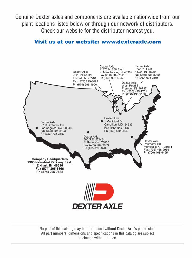
Genuine Dexter axles and components are available nationwide from ourplant locations listed below or through our network of distributors.
Check our website for the distributor nearest you.
Visit us at our website: www.dexteraxle.com
Dexter Axle222 Collins Rd.Elkhart, IN 46516Fax (574) 295-8094Ph (574) 295-1900
Dexter AxleWest Pearl St.Fremont, IN 46737Fax (260) 495-1701Ph (260) 495-5100
Dexter AxlePerimeter RdMonticello, GA 31064Fax (706) 468-2966Ph (706) 468-6495
Dexter Axle2700 S. Yates Ave.Los Angeles, CA 90040Fax (323) 724-8193Ph (323) 726-3157
Dexter Axle500 S.E. 27th St.El Reno, OK 73036Fax (405) 262-9089Ph (405) 262-6700
Dexter AxleRoad 75 EastAlbion, IN 46701Fax (260) 636-3030Ph (260) 636-2195
Dexter Axle11870 N. 650 EastN. Manchester, IN 46962Fax (260) 982-7511Ph (260) 982-4047
Company Headquarters2900 Industrial Parkway East
Elkhart, IN 46516Fax (574) 295-8666Ph (574) 295-7888
Dexter Axle1 Municipal Dr.Carrollton, MO 64633Fax (660) 542-1133Ph (660) 542-2232
No part of this catalog may be reproduced without Dexter Axle’s permission. All part numbers, dimensions and specifications in this catalog are subject
to change without notice.

www.dexteraxle.com2900 Industrial Parkway East • Elkhart, IN 46516
Fax: 574-295-8666 • Ph. 574-295-7888
4/06 © Dexter Axle 2006LIT-121-00