Development of wear-resistant coatings compounds for high ...researchonline.ljmu.ac.uk/3075/1/A.А....
32
Development of wear-resistant coatings compounds for high-speed steel tool using a combined cathodic vacuum arc deposition A.А. Vereschaka 1a , M.A. Volosova 1 , A.D.Batako 2 , A.S. Vereshchaka 1 ; B. Y. Mokritskii 3 1 Moscow State University of Technology (MSUT "STANKIN"), Russian Federation a (Corresponding author, [email protected], +7 9169100413 2 Liverpool John Moores University, UK, [email protected] 3 Komsomolsk-na-Amure State Technical University, 27, Komsomolsk-na-Amure 681013, Russian Federation Abstract The article presents the results of working out for a wear-resistance complex (WRC), formed on the working surfaces of the HSS tools, in order to increase their efficiency. Wear-resistant complex includes nitride layer, which increases the plastic strength of the HSS tool cutting wedge and cutting tool wear resistance, as well as a three-layer nanostructured composite coating, increases lifetime of a HSS tools. Equipment combining the processes of ion nitriding in the gas plasma and the formation of nanostructured multilayer composite coatings in the filtered metal-gas plasma cathode vacuum arc discharge has been developed. Particular attention is paid to the study of the regularities of formation of the nitride layer and optimization of its parameters and structure, as well as the study of the properties and structure of functional coating layers, depending on the parameters of the deposition process. The parameters of the combined cathodic vacuum arc processing (CCVAP), provides a minimum intensity of tool wear during the cutting process. Also conducted research certification cutting tool properties of HSS with WRC, which made it possible to determine the optimal parameters WRC, which gives the maximum increase in tool life for a variety of cutting conditions as compared to uncoated HSS tool, as well as with standard commercial coatings. Keywords: Arc-PVD processes, wear-resistant complex, HSS tool life 1. Introduction Modern machining and metal cutting increasingly uses high-efficiency cutting tools made of HSS with wear-resistant coatings, which are obtained using cathode vacuum arc synthesis techniques (arc-PVD). HSS cutting tools with vacuum-arc coating significantly increase the efficiency of a
Transcript of Development of wear-resistant coatings compounds for high ...researchonline.ljmu.ac.uk/3075/1/A.А....

Development of wear-resistant coatings compounds for high-speed steel tool using a
combined cathodic vacuum arc deposition
AА Vereschaka1a MA Volosova1 ADBatako2 AS Vereshchaka1 B Y Mokritskii3
1Moscow State University of Technology (MSUT STANKIN) Russian Federation
a(Corresponding author ecotechramblerru +7 9169100413
2Liverpool John Moores University UK adbatakoljmuacuk
3 Komsomolsk-na-Amure State Technical University 27 Komsomolsk-na-Amure 681013
Russian Federation
Abstract
The article presents the results of working out for a wear-resistance complex (WRC) formed on
the working surfaces of the HSS tools in order to increase their efficiency Wear-resistant complex
includes nitride layer which increases the plastic strength of the HSS tool cutting wedge and
cutting tool wear resistance as well as a three-layer nanostructured composite coating increases
lifetime of a HSS tools Equipment combining the processes of ion nitriding in the gas plasma and
the formation of nanostructured multilayer composite coatings in the filtered metal-gas plasma
cathode vacuum arc discharge has been developed Particular attention is paid to the study of the
regularities of formation of the nitride layer and optimization of its parameters and structure as
well as the study of the properties and structure of functional coating layers depending on the
parameters of the deposition process The parameters of the combined cathodic vacuum arc
processing (CCVAP) provides a minimum intensity of tool wear during the cutting process Also
conducted research certification cutting tool properties of HSS with WRC which made it possible
to determine the optimal parameters WRC which gives the maximum increase in tool life for a
variety of cutting conditions as compared to uncoated HSS tool as well as with standard
commercial coatings
Keywords Arc-PVD processes wear-resistant complex HSS tool life
1 Introduction
Modern machining and metal cutting increasingly uses high-efficiency cutting tools made of HSS
with wear-resistant coatings which are obtained using cathode vacuum arc synthesis techniques
(arc-PVD) HSS cutting tools with vacuum-arc coating significantly increase the efficiency of a
wide range of manufacturing operations with intermittent and heavy cutting The performance
accuracy and quality of machining are increased with subsequent reduction of consumption of
expensive tool materials improved environmental aspects in dry cutting without use of cutting
fluids [1] However HSS cutting tools are still the weakest link in the technology of metal cutting
This is true for HSS-tools with complex geometric profile which are currently widely used for
various cutting operations [1-8]
Arc-PVD processes has a significant application in manufacturing of cutting tools made of
different materials especially HSS which is characterized by relatively low heat resistance since
Arc-PVD processes are implemented in temperature range of 200-800degС [1 4 7 8 10 19] Arc-
PVD processes provide a range of opportunities for the formation of multi-layered composite
coatings with nano-scale structure based on single- and multi-carbides nitrides oxides borides
and their mixtures with elements of IV-VI refractory metals of the Periodic Table of Elements
including those alloyed with the various elements (Al Si Cu etc) to improve structure and
properties [4 5 6] The possibility of forming such coatings with crystallite sizes and thicknesses
in the range of tens of nanometers allow reducing defects of crystallites in super-thin layers and
bringing their strength to a possible theoretically level In addition it is possible to produce
coatings with optimum balance of the major characteristics ie hardness and toughness along with
high wear resistance of the tool This allows maximizing crack resistance of coatings increasing
durability of coating in the contact areas of the tool with the machined part even under considerably
heavy thermoplastic loads [9 10 11 12]
An analysis of the trends to improve HSS tool with wear-resistant coating [1 4 7 8] shows that
this improvement is related to the development of various types of coatings with nano-dispersed
structure and multi-layered compositional architecture formed using PVD technologies The
combined methods of synthesis of coatings are increasingly used since they integrate advantages
of chemical-thermal and ion-plasma technologies or combine different types of physical and
chemical effects on working surface of the tools [5 6 7 8 11] In particular to produce targeted
modification of surface properties of the tool material coating deposition is accompanied or
assisted by simultaneous action on the deposited condensates and tool surface with low and
medium energy plasma (stimulated thermo-chemical treatment by inducing ion energies of 03-10
keV) high energy ion beams with energies of up to 40-500 keV (ion implantation) The techniques
to combine ion-plasma coating synthesis with laser action [1 8] are noticeably used and these
techniques allow a better management of the process of metal arc evaporation and homogeneity
of plasma flow Additionally these techniques provide an opportunity of targeting action on
surface coating defects directly during the synthesis or after the completion of coating formation
and that allows improving significantly the quality of coating tool and tool performance
The analysis of the properties of some refractory compounds that are most suitable for wear-
resistant coatings for cutting tools from the point of view of thermodynamics and the conceptual
dual nature of coating as an intermediate processing medium between tool and the machined
material the coatings secure simultaneously an increase resistance to wear at the contact areas and
a reduced operational thermo-mechanical stresses that initiate wear [1 8 10] This analysis
suggests that the use of mono-layered coatings consisting of one metal compounds (for example
TiN) does not meet the basic requirements for wear-resistance Therefore in practice tool
manufacturers increasingly apply nano-structured multi-layered composite coatings with varying
chemical composition and properties [9 10 11 12-19]
Thus the increase the performance of the complex profile HSS tool for a variety of cutting
conditions on the basis of the development of wear-resistant complexes applied to its surface
creating a combined equipment and combined cathodic vacuum arc processes (CCVAP) is the
main focus of this study
2 Theoretical background
The analysis of the causes of intense fracture of coatings at contact areas of HSS tool and the
studies of the kinetics and mechanisms of tool wear with different coatings [125 89] show that
despite the significant positive contribution of coating to the reduction in wear intensity in contact
areas their performance is much lower than expected In particular the durability of different
coatings at contact areas of HSS tool is 05-20 of the lifetime of tool to complete failure (Table
1)
Table 1 The ratio of operating time of the HSS tools before the destruction of the TiN coating to
the tool life in percent
According to the data [1 4 5 8 9] different types of HSS-tools (drills shaping cutters worm
and end milling cutter cutting inserts) are characterized by the durability of standard types of
coatings (such as TiN and TiAlN) not exceeding 05-20 of tool life
Tables 1 characterize the relation of an operating time of a coating before destruction concerning
the period of tool life for various HSS tools in percentage
The results of the studies of the efficiency of coatings on HSS-tools showed that the immediate
cause of reduction of plastic strength of cutting tool with coating and subsequent intensive brittle
fracture of coatings at the contact areas is the transformation of contact stresses on working
surfaces of tool and the shift of isotherms of maximum temperatures directly to cutting edge This
effect is illustrated in Fig 1 [1]
Figure 1
The critical stresses appear at the borders of HSS-coating section and their magnitude is largely
dependent on the difference in thermo-physical and physical-mechanical properties of the coating
material and HSS [1 8] micro-stresses in surface layers of tool material after full thermal
treatment and sharpening as well as on the stresses generated at the border of HSS and coatings
especially with a low adhesive strength between the two surfaces This fact means that there is a
need in the development of new coating compositions for HSS-tool with improved properties In
this study M2 tool steel is considered as base material for HSS tool to be coated These new
coatings should secure a low tendency of seizure between the tool material and the machined
material In addition these coatings should improve the performance of contact processes and chip
formation and a low frictional energy This in its turn will lead to an increase the predisposition
of cutting edges to elastic-plastic bending a reduction of plastic strength factor of the tool and an
increase of the probability of intense brittle fracture of surfaces These tendencies increase with
the increase in strength and hardness of machined material as along with the predisposition of the
machined material to physical-chemical interaction with tool material and the increase in depth
of cutting
Let us consider the problem of estimating the plastic strength factor of tool with coating According
to the theory of Huber-Mises-Hencky the plasticity condition for a perfectly plastic tool material
the equivalent stress in the cutting part of the tool in a model of plastic strain in cutting with a
single shear plane can be determined using the following relationship
120590119864 = radic1205901199102 + 120590119911
2 minus 120590119910120590119911 + 31205911199101199112 (1)
where 120590119910 120590119911 and 120591119910119911 are stresses
In free plastic orthogonal cutting the conditions for a plastic metal flow are as follows
σeq max=σyi where σyi is the yield point of tool material In this case the tool plastic strength factor
119899 can be calculated as
119899 =σyi
120590119864 119898119886119909 (2)
Since the strain state of contact layers along the rear surface approaches the state of simple shear
the equivalent stresses can be expressed in terms of contact stresses acting on the front and back
surfaces of the tool [2]
120590119864 = radic3(120590120572 + 120591120572)2 + 1205901205742 (3)
Where are normal and shear stresses on flank face σγ is a normal stress on rake face of
cutting tool respectively
With respect to equation (3) the plastic strength factor of the tool can be determined from the
following expression
119899 =120590119879
radic3(120590120572+120591120572)2+1205901205742 (4)
Analysis of relationship (2)-(4) can be noted that the higher the yield stress σyi relatively equivalent
tension σeq max the higher the safety factor for plastic strength of tool material and less the
probability of a plastic change of the cutting wedge tool
Analysis of the reasons for the lower efficiency of coatings on HSS tools compared with
the efficiency of coatings on carbide tools showed the following [156789] The main reason for
increasing the intensity of distraction of coatings on HSS tools is a high probability of plastic
changing the shape of the cutting tool wedge that leads to rapid distraction of coatings [1]
On the basis of the results obtained the principles of improving durability of wear-resistant
coatings at the contact areas of HSS-tool were developed According to these principles an
increased durability of coatings on working surfaces of complex HSS-tool can be achieved by
increasing the plastic strength of the cutting wedges of HSS-tool [1] This was implemented by
depositing on working surfaces of HSS-tool four-component wear-resistant complex (WRC)
These (WRC) consisted of a thermo-stabilizing layer (TSL) an adhesive underlayer (AU) a
transition layer (TL) and wear-resistant layer (WRL) This structure is illustrated in (Fig 2)
Figure 2
Each of the elements of wear-resistant compound performs a specific technological role The
thermo-stabilizing (reinforcing) layer provides the increase of plastic strength and stiffness of
cutting wedge of HSS-tool The wear-resistant layer enhances the durability of contact areas of
HSS-tool due to their increased hardness with a physical and chemical passivity in relation to the
machined material and a high thermodynamic stability The adhesive underlayer provides an
increased adhesive strength between the wear-resistant coating and HSS-substrate due to an
increased crystal-chemical compatibility of their properties The transition layer provides a high
adhesive strength between the wear-resistant layer and the adhesive underlayer
The flow limit of thin surface layers (20-100 microns thick) on the working surfaces of HSS-tool
can be increased by means of preliminary surface hardening using additional processes However
it is more cost effective to carry out the combined ion-plasma treatment of HSS-tool in one
technological cycle For this purpose a multi-purpose vacuum arc station VIT -4 was developed
(see illustration in Fig 3) This experimental rig was used to deposit the wear-resistant coating by
combining vacuum arc treatment with the stimulated thermo-chemical treatment (ion nitriding) to
generate the thermo-stabilizing layer The filtered cathodic vacuum arc deposition (FCVAD) was
used to form of the adhesive underlayer intermediate and wear-resistant layers
Figure 3
3 Experimental
31 Deposition of wear-resistant complex (WRS)
A combined ion-plasma process on installation VIT-4 was used to deposit the wear resistance
complex ndashWRS on the HSS-substrates with the following phases
In the first phase the thermo-stabilizing layer (TSL) was formed The target 1 of titanium was
evaporated by cathode spots of vacuum arc and used as a cathode for arc discharge The special
screen 4 located between cathode 1 and anode 2 divides the chamber 5 into two zones filled with
the metal-gas plasma (on the left side of the screen) and gas plasma (on the right side) This screen
is impermeable to micro-droplets neutral atoms 6 and ions of metal 7 emitted by the cathode spots
from the surface of target 1 Only electrons 8 penetrate through the screen 4 and on their way
toward the anode 2 they ionize gas which is fed into the chamber and subsequently generate gas
plasma which is almost free of metallic particles The HSS-samples 8 located in plasma were first
exposed to positive potential and heated by electrons and then when fed with a negative potential
they were subjected to ion nitriding
Upon completion of the procedure of full formation of the thermo-stabilizing layer the screen 3
was shifted aside and as soon as the ions evaporating from the surface of the cathodes (Ti Cr Al)
reached the surface of the HSS-samples 8 of the layers of the coating were deposited in the
following sequence adhesive underlayer intermediate layer and и wear-resisitance layer
During nitriding the process modes were varied as follows the temperature was between
420510degC the concentration of N2 in gas mixture with argon was around 10100 atm the
nitriding time was in the range of 40100 min Since the pressure range at which the vacuum arc
discharge is obtained is sufficiently narrow in all cases the nitriding process was carried out at a
pressure of 97510-1 Pa In the process of identifying optimal parameter of depositing the wear-
resistant coating Ti was used as an adhesive underlayer TiN was used as an intermediate layer
and TiCrAlN was used for the wear-resistant layer nitriding layer was used as the thermo-
stabilizing layer The time of deposition of the thermo-stabilizing layer varied between 40 and
100 min Other process parameters remained constant in all cases the temperature was 450-470
degC the reference voltage was 120V the arc current on Ti-cathode was 80A the pressure in the
vacuum chamber was 26 10-1 Pa and the ion current density was 05 Amm2
32 Metallographic studies
Micro cross sections of HSS samples were used for metallographic studies The cross sections
were produced by the standard methods using equipment from Struhers
The micro-hardness was measured with a POLYVAR microscope equipped with the MICRO-
DUROMAT 4000 micro-hardness measurement system The nitride layer effective and total
thickness of the layer was evaluated The effective thickness of the nitride layer was measured as
the distance from the sample surface to the section where hardness became H = 98 Nmm2 The
total thickness was assumed as the distance from the sample surface to the section with hardness
corresponding to the initial hardness of HSS (H = 88 Nmm2)
The phase composition and structure of the nitride layer were investigated using X-ray crystal
analysis with an automated difractometer DRON-4 which was computer-controlled and had a
system to record the spectra Symmetrical recording (filming) of samples reflection was carried
out using X-ray tubes with copper and cobalt radiation This allowed estimating the average phase
composition at different depths from the surface down to ~ 7 microm and ~ 2 microm respectively In some
cases to determine the phase composition of the thin surface layer of up to 05 microm the method of
sliding X-Ray beam (CuKα radiation) with constant angle of entry (α = 5deg) was used Data
processing of the spectra was carried out in software
The following characteristics of the obtained coatings were studied thickness (method Calotest
apparatus Fischer Sindelfingen) adhesional strength to the substrate material (method
Scratchtest apparatus Csem Revetest) nanohardness and modulus E1 (method NanoTest
apparatus Micromaterials LtdWrexam) Studies on nanoindentometer were carried out using
Berkovich indenter by standard methods For each sample of carbide with obtained coating
research of nanohardness was carried out at 25 measurements on a square of 100x100 μm2Studies
of crystal-chemical properties of NMCC obtained on the working surfaces of carbide inserts were
carried out using a scanning electron microscope (SEM) JSM-6700F with an attachment for
spectral dispersion spectrometry (EMF) JED-2300F manufactured by the Company Jeol The
study of residual stress in the coating was carried out using the method of X-ray diffraction (XRD)
using CoKα radiation based on X-ray analysis discussed in detail in reference [8]
33 Cutting performance of HSS-tools with wear-resistant coatings
Here standard square HSS inserts (18 x 18 x 6 mm) made of M2 SS tool steel (6 W 5 Mo)
with radius r = 12 mm subjected to standard thermal treatment were used for turning and
symmetric face milling
The experimental tests for the HSS tools with the developed wear-resistant coating were carried
out under continuous traverse turning on a lathe with thyristor drive which allowed maintaining
constant cutting speed when machining workpieces with different diameters
The interrupted cutting in symmetric face milling was also undertaken To exclude the influence
of radial motion variation of cutting teeth on tool wear the tests were carried out with single-tooth
cutters Standard steel HB 200 was the material machined and the tests were carried out with the
following machining parameters
Traverse turning cutting speed v = 82 mmin feed f = 02 mmrev depth of cut ap = 15 mm
Face milling cutting speed v = 89 mmin feed fZ = 015 mmteeth depth of cut ap = 15 mm
milling width B = 45 mm
The cutting period at which the tool was changed was T = 60 min In this study the maximum
allowable flank wear of HSS-tool was set to be VBmax 045-05 mm
The flank wear land VBmax was measured using a microscope BMS-1C Experimental works were
repeated 3-5 times to ensure sufficient repeatability and reliability of the results
The optimization of for the vacuum plasma treatment of samples was carried out analytically using
the mathematical model suggested by [6] To construct mathematical relations to reveal connection
between time of nitriding (τN) temperature of nitriding (ΘN) nitrogen fraction in gas mixture with
argon during nitriding (КN) coating deposition time (τC) and their influence on wear of HSS-tool
in traverse turning and face milling the following mathematical model with exponential power
was used
VB = 1198881205531198731198861119870119873
11988621205911198731198863120591119862
1198864 exp [1198871120553119873 + 1198872 119870119873 + 1198873 120591119873 + 1198874120591119862] (6)
The unknown parameters (c a1 an and b1 bn) were defined using experimental data which
were processed in a software package called MODELUNI A function h3 = f (ΘN RN τN τC) was
defined and differentiated using partial derivatives The desired optimal modes for vacuum plasma
treatment were obtained by solving the first derivative of h3
The unknown parameters (c a1 an and b1 bn) were defined using experimental data which
were processed in a software package called MODELUNI A function VB = f (ΘN RN τN τC)
was defined and differentiated using partial derivatives The desired optimal modes for vacuum
plasma treatment were obtained by solving the first derivative of VB
4 Results
41 Structure and properties of wear-resistant complex
The studies carried out have shown that during the formation of the thermo-stabilizing layer of the
wear-resistant complex on the HSS-samples the composition of gaseous medium its temperature
and the time have profound effect on its structure properties (Table 2)
Table 2
It was revealed that the surface TS-layer of nitride HSS-samples with 100 N2 contained in
excess ε-phase of (FeMe)2N nitrides of alloying elements Mo2N (W2N) carbides (or
carbonitrides) of Fe3(WMo)3 (C N) In Addition to this α-phase as a solid solution of carbon and
nitrogen in Feα (martensite) were detected in the M2 tool steel substrate surface layer Recording
(filming) using the method of sliding X-ray beam shows that at depths of up to ~ 1 microm there was
continuous layer of nitride in the form of ε-phase in case of nitriding with pure nitrogen In the
formation of nitride layer in gas mixtures such as N2Ar the formation of ε-phase is blocked while
molybdenum Mo2N nitrides in the surface layer are maintained and their volume decreases from
~ 56-55 (at depth of up to~ 2 microm) up to 1 (at depth of ~ 7 microm)
X-ray diffraction data are in good agreement with the results
metallographic investigations In the microstructure of the surface layer samples
nitrided in an atmosphere of 100 N2 as well as a high content of nitrogen in admixture with
argon gas (80 N2) revealed good solid nitride layer having a thickness of 05 to
15 mm (Fig 4a) In case of nitriding in the gas mixture with a nitrogen content of less than 60-
80 of the surface nitride layer is absent (Fig4 bc) Dark herb layer
has a higher hardness (more than 98 kNmm2) and corresponds approximately
effective thickness of the nitrided layer HSS steel M2 The high hardness of this layer
due to the fact that apparently it consists of a nitrogenous martensite and dispersed
nitrides - ε and γ-phase and nitrides of the alloying components Mo W Cr V
However γ-phase and a chromium nitride and vanadium not detected
X-ray analysis is possible due to their dispersion and small quantity
Follow the dark area wide transition zone where the hardness remains
increased due to the presence of nitrogen in the α-solid solution the grass is almost as
a core (base)
The tests of the strength of adhesive bond of wear-resistant complex with HSS-samples formed
in gas mixtures of N2 and Ar showed a high adhesive strength of the wear resistant complex and
almost complete absence of flaking of the coating and crack formation This was observed as a
characteristic for nitride HSS-samples in 100 N2 The main coatings parameters ie
microhardness thickness strength of adhesion of coating-substrate and surface morphology
were studied The composition of the layered structure of Ti Cr Al composite was investigated
and controlled The results of the main parameters surface structure and morphology of developed
functional coatings Ti-TiN-TiCrAlN are presented in Table 3
Table 3
The analysis of the data in Table 3 showed that the wear resistant layer Ti-TiN-(TiCrAl)N has a
multilayered structure with the thickness of sublayers down to 15-25 nm The mean ratio of Ti Cr
and Al in the wear-resistant layer of TiCrAlN was 025 025 015 respectively
Ti02Cr02Al015N035 layer had a columnar structure oriented perpendicularly to the plane of TiN-
underlayer The thickness of the sublayers in the intermediate TiN-layer was in the range of 25 nm
as illustrated in Fig 5 and for this reason the multilayered composite coating are considered as
nano-scale coating
Fig5
42 Investigation into cutting performance
The experimental work conducted HSS cutting tools coated using the combined cathodic vacuum
arc treatment revealed the parameters with dominant influence on the cutting properties of tool
These parameters were the temperature (ΘN) the duration of the nitriding process (τN) fraction of
nitrogen in gas mixture of argon (КN) and the time of subsequent application of wear-resistant
coatings (τC)
Fig 6 ab show the effect of parameters of combined vacuum plasma treatment on the wear rate
of HSS-tool in traverse turning and face milling of steel Here J is the wear out rate expressed as J
= VB(v T) where VB ndash flank wear land v ndash Cutting Speed T- tool life
Figure 6 ab
It indicates that in all cases the tool wear as function of modes of vacuum plasma process has a
local minima The process of the experimental data allowed building a model showing the
relationship of flank wear rate of coated tools with the modes of vacuum plasma process
119881119861119898119886119909 =038 exp [0003 120553119873+44119870119873+221120591119873+13120591119862]
120553119873138119870119873
132120591119873073120591119862
09 (7)
119881119861119898119886119909 =274 exp [00032 120553119873+173119870119873+1075120591119873+082120591119862]
12055311987316119870119873
104120591119873072120591119862
082 (8)
Using these relationships allowed defining the numerical values for optimum process parameters
of vacuum plasma modes which secure a minimum wear tool rate in turning (eq7) and milling
(eq8) as presented in Table 4
Table 4
The metallographic studies showed that the wear-resistant complex (WRC) emerged from the
modes of combined vacuum plasma treatment had a minimal tool wear rate and was characterized
by the following observations
- In a uninterrupted turning the effective thickness of the TSL-layer - hN = 50-55 μk
microhardness 119 121 kN mm2 at a thickness of the outer coating layers (Ti-TiN-
TiCrAlN) hC = 6 μk
- In interrupted milling effective thickness of the TSL-layer - hN = 30-35 microns
microhardness 105 107 kN mm2 at thickness of the coating layer (Ti-TiN-TiCrAlN) hC =
4 μk
To evaluate the performance and reliability of HSS-tool with developed wear-resistant coatings
laboratory and industrial tests were conducted For the research purpose a batch of HSS-tools was
manufactured and coated with the wear-resistant compound developed on the basis of N-Ti-TiN-
TiCrAlN system with relevant parameters as defined and recommended by this work
Considering that cutting temperatures have a strong softening effect on the HSS-tool with new
coatings which is related with to transformations in HSS the effect of machining time on the
structure along with the magnitude of residual austenite was studied (see Table 6) These
machining tests were undertaken for tools with various coating In addition the changes in micro-
hardness of the cutting edges was investigated This is illustrated in Fig 6
Table 6
Figure 6
As illustrated in Table 6 and in Fig 6) during the unset of wear (cutting time around 280 seconds)
the surface layer of the tool with new coating at a depth of up to 10 microm undergoes some hardly
noticeable changes in comparison with uncoated HSS-inserts or HSS-inserts with standard
coatings
The difference is especially visible in the surface layers at a depth of 25 microm as portrayed in Table
6 In particular for inserts with the wear-resistant coating the tests revealed a smaller volume of
residual austenite and a decrease in the parameter (211) which characterizes the distortion of
the crystal lattice in HSS-steel At the same time the tests showed a lower softening in local
volume of tools with new wear-resistant coating during in the unset of wear and especially during
rapid wear compared with the reference HSS-inserts (see Fig 6)
In the rapid wear phase the tests showed satisfactory conditions of surface layers of the tools with
the new wear-resistant coating despite considerably longer cutting time (up to 820 s) compared to
the reference samples which secure only 280 s and samples with standard coating secured up to
680 s
Thus the thermo-stabilizing layer as an element of the wear-resistant compound had an extremely
important contribution to the enhancement of plastic strength of cutting edges of HSS-tool and to
the increase of its resistance to thermal softening under the thermo-mechanical loads generated
during the cutting process This finding allows predicting with confidence the increase in the
durability of tool due to wear-resistant coating and its positive contribution to improving the
performance of HSS-tool
The tests also included an investigation into the compositions of the coatings which were
developed for different cutting conditions These results are presented in Fig 7 and 8 which lead
to the following observations
The developed coating (eg N-Ti-TiN-TiCrAlN) increases the wear resistance of HSS-tool up to
10 times compared with the reference uncoated tools and up to 15-8 times compared with tools
with standard coatings (Fig 7 and Fig 8)
Figure 7
Figure 8
With the increase in cutting speed the performance of tool with the new coatings increases
significantly This is shown in Fig 7 curves 1-3 versus curves 4 and 5 This indicates the
significant contribution of the thermo-stabilizing layer which enhanced the plastic strength of
cutting edges of HSS-tools and increased in the durability of coatings at the contact areas of the
tools It was found that the feed rate and especially the depth of cut had the same influence on the
performance of the newly coated as on the tools with standard coatings Fig 9 illustrates some
samples of coated tools and the experimental configurations for laboratory tests in interrupted face
milling and traverse turning
5 Discussion
The results obtained prove that the formation of the thermo-stabilizing layer in 100 percent clean
nitrogen significantly limits the performance that could be achieved by the application of wear-
resistant coatings This fact is related to the formation of nitride zone on the thermo-stabilizing
layer surface consisting of high-nitrogen ε-phases characterized by an increased hardness and
brittleness It is known [1] that the presence of ε- phase does not reduce the strength of the adhesive
bond between the coating and HSS-substrate and that is one of the most important conditions for
the successful operation of tool with coatings
The analysis of the results of the industrial tests conducted with HSS-tools with the new coatings
showed that for the inserts operating under intermittent cutting conditions or continuous cutting
with large depth of cut the formation of thin solid nitride zone (ε-phase) on the thermo-stabilizing
layer surface leads to chipping of cutting edges already in the first minutes into the machining
process This is related to the fact that during the formation of continuous layer of brittle ε-phase
the plasticity of the thermo-stabilizing layer greatly reduces The optimal structure of the thermo-
stabilizing layer for milling should be more viscous and resistant to varying loads This provides
solid solutions of nitrogen in the martensite under insignificant volume of dispersed nitrides of
alloying elements This structure also provides greater strength of the adhesive bond between the
outer layer coat and HSS-substrate
For HSS-tool operating under conditions of continuous cutting eg traverse turning the optimal
structure is represented by nitrous martensite with small amount of ε (γ΄)-phase and nitrides of
alloying elements (W Mo Cr V) This structure provides an improved strength of the adhesive
bond between the outer coat and the substrate higher resistance to plastic strain and heat resistance
The X-ray analysis allowed observing that during the formation of the thermo-stabilizing layer
its phase composition structure and properties can be controlled depending on the targeted
operating conditions of cutting tool by varying the ratio of nitrogen and inert gas For example for
continuous cutting the optimum structure for the thermo-stabilizing layer contained solid nitrogen
solutions in martensite without formation of ε-phase
It was found that during the processes of the combined cathodic vacuum arc deposition of the
coating on HSS-substrates the structure hardness and thickness could be controlled during the
formation of the thermo-stabilizing layer by varying process parameters such as temperature
duration and composition of gas mixture
When optimizing the parameters of the cathode vacuum arc treatment of HSS-tool not only the
parameters of the process of the thermo-stabilizing layer formation but also the parameters of
subsequent deposition of other layers (adhesive under layer transition layer wear-resistant layer)
should be taken into consideration
Based on these studies conducted the mathematical models were developed revealing the
relationships between the most important parameters of the combined cathodic vacuum arc
treatment and wear of HSS-tool for different processing conditions
5 Conclusion
In the modern metalworking industry are widely used profiled HSS tools with wear-resistant
coating or chemical-thermal treatment but the effectiveness of such HSS tools still substantially
below the required modern technological processes In this connection the further improvement
of HSS tools will be important scientific task
The paper presents the results of studies related to the development of processes technologies
and equipment for the combined cathodic vacuum arc forming a wear-resistant complex (WRC)
on the working surfaces of HSS tools in order to improve its effectiveness Wear-resistant
complex (WRC) includes thermo-stabilizing layer (TSL) and three-component nanostructured
layers AU-adhesive layer IL-intermediate layer WRL ndashwear resistance layer
Among elements of a wear-resistance complex (WRC) the important role is carried out by the
thermo-stabilising layer raising plastic durability of cutting part of the HSS tool durability of a
wear-resistance coating and its positive influence on contact processes at cutting and life time of
the HSS tools For the formation of thermally stabilizing layer developed in the process of
nitriding nitrogen-argon gas plasma vacuum arc discharge which allows you to control the phase
composition and properties of the nitrided layer (TSL) depending on the operating conditions of
the HSS tools
It is established that at formation of a TSL by nitriding in the gas environment containing 60N2
and 40Ar bloking up formation of fragile ε - phases and is provided high enough plastic
durability of the HSS tool cutting part that promotes efficiency increase for nano-scale coatings
Ti-TiN-TiCrAlN and as much as possible reduces intensity of wear process of the HSS tools at
uninterrupted cutting (turning drilling threading etc)
At formation of a TSL in the gas environment containing 30 N2 and 70 Ar formation ε - phases
also is blocked and the layer consists mainly from nitrogenous martensit that also provides high
plastic durability of a cutting part of the HSS tool and efficiency of coating Ti-TiN-TiCrAlN Such
structure is optimum and provides the maximum lifetime of the HSS tools at interrupted cutting
(milling planning gear shaping etc)
Designed as wear-resistant coating composition having a ternary architecture comprising an AU
an IL and a WRL which is deposited on the working surface of the HSS tool after forming thermo-
stabilizing layer Structures parameters and conditions of coating deposition for all coating layer
were optimized It has been established that all coating layers have a thin multilayer substructure
with thickness of sublayers of 15-25 nm and the size of grains did not exceed 5-10 nm
The process parameters of vacuum-plasma treatment are interconnected in a complex dependence
and should comprehensively optimized for specific operating conditions of the HSS tools The
greatest influence on the wear of HSS tools provide - nitriding time - nitriding temperature - the
concentration of nitrogen in the gas mixture of argon and parameters coating deposited after the
formation of thermally stabilizing layer - composition - deposition time - the thickness of the
coating layers and sublayers
Study the cutting properties of HSS cutting tools with developed WRC for various machining
operations (turning drilling milling) showed significant benefits of such a tool as compared to the
nitrided HSS tools and a tools with a multilayer composite coatings
6 References
[1] Vereschaka AS 1993 Efficiency of the cutting tool with wear resistant coating -
Mashinostroenie Moscow 336 p
[2] Loladze TN 1980 The strength and wearresisnance of the cutting tool - Mashinostroenie
Moscow 320 p
[3] Alami J Persson POA Music D Gudmundsson JT Bohlmark J Helmersson U (2005) On-
assisted Physical Vapor Deposition for Enhanced Film Properties on Nonflat Surfaces Journal of
Vacuum Scienceand Technology A Vacuum Surfaces and Films 23(2) p 278ndash280
[4] Biermann D (2007) Influence of the Coating on the Maximum Width of Flank Wear Land by
Turning the Austenitic-ferritic Steel X2CrNiMoN 22-5-3 Proceedings of the 6th International
Conference THE Coatings p 97ndash106
[5] Lierat F Vereschaka A 1999Entwicklungsstand und - trends der Hartstoffbeschichtung
Tagungsband Magdeburger Produktionstechisches Kolloquium MPK99 Die Wissensintensive
Production ISBN 3-00 - 004180-x) 7
[6] Sablev LP Andreev AA Grigoriev SN Metel AS US Patent 5503725 Europatent
0583473 DE Patent 69227313Т2
[7] Lierat F Vereschaka AS Pankov A Lapin V DE Patent 19733517 A1 C23 C 3000
[8] Gorovoy AP Fegorov SV Volosova MA 2001 Influence of plasma nitriding process two-
stage vacuum-arc discharge on the structure of the surface layer of high-speed steel The
interaction of ions with the surface Proceedings of the XV International Conference T2 M
MAI p 318 ndash 320
[9] Lierat F Vereschaka A 1998 The main trends of Vacuum-ARC technology synthesis of
multi-layered coatings for cutting tool perfection IX Internationales Productionstechnisches
kolloquium PTK-98 Berlin p211-225
[10] Loladze TN 1980 The strength and wearresisnance of the cutting tool - Mashinostroenie
Moscow 336 p
[11] Grigoriev SN Vereschaka AA Vereschaka AS Kutin AA 2012 Cutting tools made of
layered composite ceramics with nano-scale multilayered coatings Procedia CIRP 1 (2012) p318
ndash 323
[12] AS Vereshchaka B Karpuschewski L Dubner 2008 Development of the method of
obtaining nanostructured functional coatings Proceedings of the Intern Scient Conf ldquoProduction
Technologyrdquo V1 p 62-68
[13] KD Bouzakis N Michailidis G Skordaris E Bouzakis D Biermann R MrsquoSaoubi
Cutting with coated tools Coating technologies characterization methods and performance
optimization CIRP Annals - Manufacturing Technology 61 (2012) р703ndash723
[14] F Sanchette E Damond Single cycle plasma nitriding and hard coating deposition in a
cathodic arc evaporation device Surface amp Coating Technology 1997 р 261 ndash 267
[15] Vereschaka A A Volosova M A Grigoriev S N Vereschaka A S Development of wear-
resistant complex for high-speed steel tool when using process of combined cathodic vacuum arc
deposition Procedia CIRP 9 ( 2013 ) р8 ndash 12
[16] Vereschaka A A Development of Assisted Filtered Cathodic Vacuum Arc Deposition of
Nano-Dispersed Multi-Layered Composite Coatings on Cutting Tools Key Engineering Materials
Vol 581 (2014) Trans Tech Publications Switzerland p 62-67
[17] Vereschaka AA Improvement of working efficiency of cutting tools by modifying its surface
properties by application of wear-resistant complexes Advanced Materials Research Vols 712-
715 (2013) Trans Tech Publications Switzerland p 347-351
[18] Vereshchaka AA Vereshchaka AS Mgaloblishvili O Morgan MN Batako AD
Nano-scale multilayered-composite coatings for the cutting tools International Journal of
Advanced Manufacturing Technology Springer-Verlag 2014 p 1-15
[19] Grigoriev SN The technology and equipment for the complex ion-plasma processing of the
cutting toosl STIN - 2 2000 P12 -16
Figure 1 Transformation of contact stresses (a) and isotherms (b) for HSS-tools with coating [1]
1 620degC 2 415degC 3 365degC 4 230degC (for M2 and M2-TiN arc-PVD) when turning steel 40X
with 119907 = 50 mmin t = 2 mm Cγ Cγc is the full length of contact between chip and front surface
of tool without and with coating C΄γ C΄γс is the length of tight (plastic) contact for tool without
and with coating σγ σγc is the normal contact stress for tool without and with coating τγ τγs is the
shear stress on front surface for tool without and with coating contact between chip and front
surface of tool without and with coating respectively
The solid line is for tool without coating dashed line is for tool with coating arrows indicate the
direction of change in stresses and isotherms
Figure 2 Schematic diagram of wear-resistant coatings formed on working surfaces of complex
HSS-tool
WRC is the wear-resistant compound TSL is the thermostabilizing layer AU is the adhesive
underlayer TL is the transition layer WRL is the wear-resistant layer CTM is the cutting tool
material (HSS) WR is the workpiece material OLM is the area of principal strains FPK is the
area of additional strains
Figure3 Principle layout of multi-functional cathodic vacuum arc rig VIT-4
1- titanium target (cathode) 2- anode 3 - aluminum target (cathode) with filtration of droplet
component 4 - special screen 5 - vacuum chamber of the installation 678- microdroplets metal
ions and electrons 9 ndash tool samples carrying planetary motion in the chamber 10 ndash turning table
with mounted tool samples 11 - gas inlet valve 12 - vacuum pumping system
3 (Al)
4 11
N2
N2Ar 10 4
9 2 1 (Ti) 6
7
8
5
12
a b c
Figure 4 The microstructure of the samples after nitriding steel R6M5 with using different gas
mixtures (times 800) 100 N2 (a) 40 N2 + 60 Ar (b) 10 N2 + 90 Ar (c)
Figure 5 Structure of a wear resistant layer of NМCC produced by FCVAD processing
a
Figure 6 Effect of vacuum plasma treatment on flank wear rate (a) face milling (b) traverse
turning
1 the temperature of thermo-stabilizing layer formation (nitriding) (ΘN) 2 the duration of
nitriding (τN) 3 the fraction of nitrogen in gas mixture with argon (KN) 4 the duration of the
process of coating application (τC)
Wear
stage
s
HSS (M2) M2-N-TiAlN M2-N-(Ti-TiN-TiCrAlN)
Sta
ge
of
the
run
nin
g t
oo
l
wea
r
Sta
ge
of
the
cata
stro
phic
to
ol
wea
r
Figure 7 Schematization of microhardness fields for cutting HSS-inserts depending on phase of
tool wear
Figure 8 Influence of cutting speed on wear resistance of tool equipped with cutting HSS-inserts
with different options of hardening treatment under turning of 45 steel with f = 02 mmrev ap=
15 mm 1 HSS inserts 2 HSS-N 3 HSS-TiN 4 HSS-N-TiAlN4 5 HSS-Ti-TiN-TiCrAlN
Figure 9 Tool life test for twist drills 68 mm DIN 338 with various types of surface modification
Tool material HSS Workpiece C 45 (HB 200) 1 - uncoated 4 - N-Ti-TiN-TiCN
Cutting parameters vc=35 mmin f=01 mm 2 - TiCN 5 - N-Cr-(TiCr)N
Depth of drilling ld=30mm 3 - TiN 6 - N-Ti-TiN
Dry cutting 7 - N-Ti-TiN-(TiCrAl)N
Table 1 Operating time of coating without fracture of complex HSS-tool
Type of HSS-tool Ratio of wear-resistance period of HSS-tool to
operating time of TiN coating to fracture
Drills 20-50
End milling cutters 15-20
Cutting taps 20-100
Shaping cutters 05-20
Worm milling cutters 10-40
Broach tools 150-200
Table 2 Effect of temperature and gas composition and thickness microhardness of the TS-layer
(nitriding time - 50 minutes)
Nitriding
temperature
The
concentration of
N2 in the gas
mixture with Ar
Microhardness
kNmm2
Effective
thickness μк
Total thickness
μк
420 10
20
40
80
100
10
10
103
106
112
10
30-40
25-30
10- 15
80
450-500
200-250
180-210
150-200
80-90
510 10
20
30
108
112
111
175
90-100
85
450
300-350
450-500
Table 3 The composition and properties of wear resistant complex (WRC)
Coating
layers
Phase contents Phase characteristics
Grains sizes μm
(nm)
Layer and
sublayers
thickness
μm (nm)
HV
GPa
F
N
∆Р
mgсm2
TSL
Fe2N Mo2 N Fe3(WMo)3
Feα(CN) 15-20 μm 40-60 μm 1250 - 549
AU α-Ti 20-30 μm
07-11 - - -
TL
Ti025N075 25-30 nm hc = 25-30 μm
hsl = 20-25 nm
25-
30
80-
100 147
WRL Ti 025 Cr025Al015N035 50-150 nm hc =28 μm
hsl = 20-25 nm
31-
32
120-
130 157
∆Р-oxidation on air at 900 degС within 1 hour F - the critical to the indenter at scratch test on
coating surfaces (criterion of adhesion)
Table 4 Effect of temperature and composition of gas mixture on thickness and microhardness of
TSL (nitride) layer (nitriding time is 50 minutes)
Temperature of
nitriding degC
Fraction of N2 in
gas mixture with
Ar
Microhardness
kNmm2
Effective
thickness microm
Total thickness
microm
420 10
20
40
80
100
100
100
103
106
112
70
30-40
25-30
10-15
8
450-500
200-250
180-210
150-200
80-90
510 10
20
40
108
112
111
175
90-100
85
450
300-350
450-500
Table 5 Values of optimal parameters to form TSL of wear-resistant complex WRC for cutting
inserts made of HSS
Parameters for TSL-layer formation Optimal values under
turning
Optimal values under
milling
Temperature of nitriding ϴN degC 500 460
Fraction of nitrogen in gas mixture
KN
06 03
Time of nitriding τN hour 067 033
Time of WRC layer formation
AUTLWRL hour 10 07
Table 6 Influence of cutting time on volume of residual austenite and lattice distortions
Tools Distance from surface microm
Before cutting After 65 s cutting
(211)∙10 -3 rad А (211) ∙10 -3 rad А
0 25 5 75 10 0 25 5 75 10 0 25 5 75 10 0 25 5 75 10
M2 steel 32 41 46 46 44 8 12 13 14 14 22 30 34 36 36 10 8 7 65 65
M2-N 24 30 30 35 36 8 75 75 7 7 20 18 17 16 16 10 6 5 4 4
M2-N-Ti-
TiN-
(TiCrAl)N
20 28 33 40 40 8 75 7 7 65 18 17 17 17 17 8 5 4 3 4
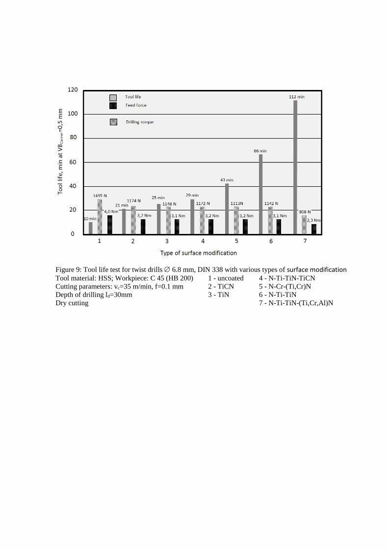