Development of the 700 C coal power · PDF fileDevelopment of the 700 °C coal power plant...
29
Development of the 700 °C coal power plant from the perspective of an European utility 4th EU South Africa Clean Coal Working Group Meeting 5 – 6 November 2012, Johannesburg Gregor Gierschner - E.ON New Build and Technology GmbH Christian Ullrich - E.ON New Build and Technology GmbH Helmut Tschaffon - VGB PowerTech e.V.
Transcript of Development of the 700 C coal power · PDF fileDevelopment of the 700 °C coal power plant...

Development of the 700 °C coal power plant
from the perspective of an European utility
4th EU South Africa Clean Coal Working Group Meeting
5 – 6 November 2012, Johannesburg
Gregor Gierschner - E.ON New Build and Technology GmbH
Christian Ullrich - E.ON New Build and Technology GmbH
Helmut Tschaffon - VGB PowerTech e.V.

2
Content
E.ON’s Project 50plus and the Cooperation COMTES+
High Temperature Valves
Repair Concept for thick-walled A617 Pipes
Challenges on the Way to the 700°C Power Plant

Gierschner, 5 – 6 November 2012, Johannesburg 3
Content
E.ON’s Project 50plus and the Cooperation COMTES+
High Temperature Valves
Repair Concept for thick-walled A617 Pipes
Challenges on the Way to the 700°C Power Plant

Gierschner, 5 – 6 November 2012, Johannesburg 4
Increased Efficiency by the use of Nickel Based Alloys
State of the Art
Future?
600°C steam
46% net efficiency
materials:
martensites and
austenites
700°C steam
50% net efficiency
materials:
nickel based
alloys

Gierschner, 5 – 6 November 2012, Johannesburg
E.ON‘s 700 °C Demonstration Power Plant
Project 50plus (stopped)
Valve casing out of
alloy617 from Hora
Valve casing out of
alloy617B
from Sempell
Net efficiency
Electrical output
CO2-Emissions
Budget
>50 % (LHV)
508 MW
670 g CO2/kWh
>1 bn €
What was done by E.ON?
Selection of plant site and size
Pre and detail engineering
Specifications for components
Offers for 700 °C components
Material research for critical
components with manufacturers
Manufacturing tests of some critical
components
Live steam pipe
Gierschner, 5 – 6 November 2012, Johannesburg
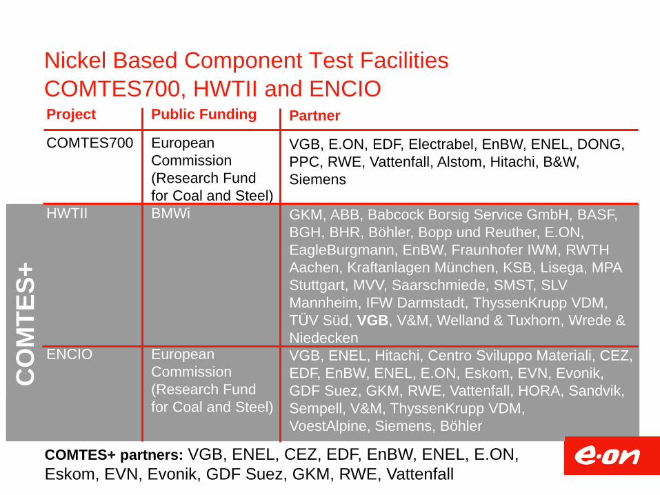
Nickel Based Component Test Facilities
COMTES700, HWTII and ENCIO Project
COMTES700
HWTII
ENCIO
Public Funding
European
Commission
(Research Fund
for Coal and Steel)
BMWi
European
Commission
(Research Fund
for Coal and Steel)
Partner
VGB, E.ON, EDF, Electrabel, EnBW, ENEL, DONG,
PPC, RWE, Vattenfall, Alstom, Hitachi, B&W,
Siemens
GKM, ABB, Babcock Borsig Service GmbH, BASF,
BGH, BHR, Böhler, Bopp und Reuther, E.ON,
EagleBurgmann, EnBW, Fraunhofer IWM, RWTH
Aachen, Kraftanlagen München, KSB, Lisega, MPA
Stuttgart, MVV, Saarschmiede, SMST, SLV
Mannheim, IFW Darmstadt, ThyssenKrupp VDM,
TÜV Süd, VGB, V&M, Welland & Tuxhorn, Wrede &
Niedecken
VGB, ENEL, Hitachi, Centro Sviluppo Materiali, CEZ,
EDF, EnBW, ENEL, E.ON, Eskom, EVN, Evonik,
GDF Suez, GKM, RWE, Vattenfall, HORA, Sandvik,
Sempell, V&M, ThyssenKrupp VDM,
VoestAlpine, Siemens, Böhler
CO
MT
ES
+
COMTES+ partners: VGB, ENEL, CEZ, EDF, EnBW, ENEL, E.ON,
Eskom, EVN, Evonik, GDF Suez, GKM, RWE, Vattenfall

Gierschner, 5 – 6 November 2012, Johannesburg 7
Content
E.ON’s Project 50plus and the Cooperation COMTES+
High Temperature Valves
Repair Concept for thick-walled A617 Pipes
Challenges on the Way to the 700°C Power Plant

Gierschner, 5 – 6 November 2012, Johannesburg Theme Date
700°C Valves from COMTES700:
Experience and Lessons Learned
CO
MT
ES
70
0 h
p b
yp
as
s v
alv
e:
Flo
w t
o C
los
e D
es
ign
(F
TC
)
Planned operation conditions for hp bypass station
100 - 500 h operation time at full load
10 - 20 times operation in bypass mode at maximum
steam conditions
Real operation conditions for hp bypass station
Daily operation of hp bypass station during start-up and
shut-down times from July 2005 to March 2008 due to
changed load profile of the host power plant Scholven F
In addition, full operation from April 2008 to August 2009
(not only start-up and shut-down)
Experience
Full functionality of hp bypass valve given during the
four years of operation
Graphite and metallic gaskets applicable for 700 °C
components in lower temperature area
Only slight but reasonable indications of erosion at
seat area and at throttle bores
But: cracks in the thick-walled valve body
8

Gierschner, 5 – 6 November 2012, Johannesburg Theme Date
700°C Valves from COMTES700:
Experience and Lessons Learned
perforated
disc
COMTES700
CO
MT
ES
70
0 h
p b
yp
as
s v
alv
e:
Flo
w t
o C
los
e D
es
ign
(F
TC
)
9

Gierschner, 5 – 6 November 2012, Johannesburg
Avoidance of small radii and notches
Favouritism of smooth transitions in geometry and good
surface quality
Avoidance of high temperature gradients
Avoidance of welds inside the valve body if possible
Reduction of notch effects and other stress concentrations by
weld design measures and grinding of the weld
Location of welds in areas where thermo mechanical stresses
are low
Avoidance of high temperature gradients
700°C Valves from COMTES700:
Experience and Lessons Learned
Avoidance of threads in pressure bearing parts wherever
possible
Avoidance of high notch effects and other stress
concentrations if threads cannot be avoided
Avoidance of high temperature gradients

Gierschner, 5 – 6 November 2012, Johannesburg
700°C Valves from COMTES700:
Experience and Lessons Learned
T1
T2
T3 F1
live steam pipe
to hot
reheat pipe
hp bypass
High temperature gradient
during start-up in this
example
Gradients lead to thermal
stresses and to a reduction
of life time
High temperature gradients
to be avoided in general
But high temperature
gradients to be avoided
particularly in high
pressure 700 °C
components due to the
thermo-mechanical
properties of nickel based
alloys
0
100
200
300
400
500
600
700
00:0
0
02:0
0
04:0
0
06:0
0
08:0
0
10:0
0
0
10
20
30
40
50
regular
operation hot start down time
°C
T1 (steam)
T2 (steam)
T3 (material)
F1
time
kg/s

Gierschner, 5 – 6 November 2012, Johannesburg Theme Date
Improved design for 700°C valves of A617B
Challenges and Solutions:
high steam temperature gradients can
cause high stresses and cracks →
appropriate preheating design
Residual welding stresses can lead to
relaxation cracking → heat treatment of
welds at 980°C/3h
Valve cover gasket and spindle seal
become ineffective due to high
temperatures → low temperatures in
sealing area
980°C/3h
after
welding
T1
T2
T1~T2
spindle seal
Valve cover
gasket

Gierschner, 5 – 6 November 2012, Johannesburg
hydraulic cylinder
steam assisted
water injection
cooling
Inlet: Ø245 x 65
Outlet: Ø168,3 x 10
2.600 kg
HP Bypass Valve for HWTII
The hp bypass valve was
originally designed for the 50+
demonstration power plant with
500 MWel and was adapted for
the 725°C test rig HWTII
A617B
forged
Flow to Open Design
(FTO)
3 stage pressure
reduction with
parabolic plug
containing 2
concentrical cages
graphite stem
packing

Gierschner, 5 – 6 November 2012, Johannesburg
Adaption of the Seat to the new Requirements
The diameter of the seat had to be
reduced from Ø 105 mm to Ø 25 mm
due to the reduced flow rates
The reduction was realised with a
build-up weld
PT test of build-up weld
build-up weld at seat

Gierschner, 5 – 6 November 2012, Johannesburg
HP Bypass Valve for
HWTII after Manufacturing
and during Installation in
GKM Power Plant
28
10
mm

Gierschner, 5 – 6 November 2012, Johannesburg 16
Content
E.ON’s Project 50plus and the Cooperation COMTES+
High Temperature Valves
Repair Concept for thick-walled A617 Pipes
Challenges on the Way to the 700°C Power Plant

Gierschner, 5 – 6 November 2012, Johannesburg 17
Repair Welds in COMTES700 Test Facility
weld
HAZ
HAZ
cracks in the HAZ of repair welds were
observed
a workable solution was not reached
during the operation time of
COMTES700
repair weld, A617 steam pipe,
220x50mm, 20kh operation
Cracks in heat affected zone (HAZ)
COMTES700 COMTES700

Gierschner, 5 – 6 November 2012, Johannesburg 18
New solution annealed A617B
Solution annealed condition shows some Cr-Carbides at the grain boundaries
Inside of the grain generally free of precipitations apart from primary precipitations
SEM TEM
100nm100nm20μm

Gierschner, 5 – 6 November 2012, Johannesburg 19
Service exposed A617B after 700°C/22kh
In service exposed material Cr-Carbides at the grain boundaries and inside
the grain are found
Formation of ‘ inside the grain
100nm 20µm
SEM TEM
’
Carbid

Gierschner, 5 – 6 November 2012, Johannesburg 20
COMTES700 Welding Tests
Ele
ctro
de
Mech
an
ize
d T
IG
98
0°C
/3h
HT
befo
re w
eld
ing
1160
°C
So
lutio
n
An
nealin
g
Weld 1 X
Weld 2 X
Weld 3 X X
Weld 4 X X
Weld 5 X X
Weld 6 X X
welding procedure
Influence of …
heat treatment
of base material
before welding
Heat treatment after
welding in any case
(980°C/3h)

Gierschner, 5 – 6 November 2012, Johannesburg 21
Influence of The Weld Technique
26 mm 12 mm
50 m
m
Electrode weld Mechanised TIG weld
COMTES700 COMTES700
The bead sequence and the heat input is more homogeneous in the
case of TIG orbital welding
Mechanised TIG leads to a significant reduction in weld size.
Internal stresses are reduced.

Gierschner, 5 – 6 November 2012, Johannesburg 22
Influence of Heat Treatments on Service Exposed Material
’ precipitates can be solved with 980°C / 3h heat treatment
Carbides being present can not be solved either by 980°C / 3h nor 1160°C / 1h.
But their number and size change significantly at 1160°C
A617B service exposed (22kh) A617B service exposed (22kh)
plus 980°C / 3h
A617B service exposed (22kh)
plus 1160°C / 1h
’ Carbid Carbid Carbid
100nm

Gierschner, 5 – 6 November 2012, Johannesburg 23
400 m400 m 400 m400 m
Electrode Weld:
Service exposed
+ 980°C/3h Pre-Weld-Heat-Treatment
Electrode Weld:
Service exposed
without Pre-Weld-Heat-Treatment
Electrode Weld:
Service exposed
+ 1160°C/1h Pre-Weld-Heat-Treatment
400 m400 m
Weld 1 Weld 3 Weld 5
TIG Orbital Weld:
Service exposed
+ 980°C/3h Pre-Weld-Heat-Treatment
TIG Orbital Weld:
Service exposed
without Pre-Weld-Heat-Treatment
TIG Orbital Weld:
Service exposed
+ 1160°C/1h Pre-Weld-Heat-Treatment
400 m400 m400 m400 m400 m400 m
Weld 2 Weld 4 Weld 6
400 m400 m 400 m400 m
Electrode Weld:
Service exposed
+ 980°C/3h Pre-Weld-Heat-Treatment
Electrode Weld:
Service exposed
without Pre-Weld-Heat-Treatment
Electrode Weld:
Service exposed
+ 1160°C/1h Pre-Weld-Heat-Treatment
400 m400 m
Weld 1 Weld 3 Weld 5
400 m400 m 400 m400 m
Electrode Weld:
Service exposed
+ 980°C/3h Pre-Weld-Heat-Treatment
Electrode Weld:
Service exposed
without Pre-Weld-Heat-Treatment
Electrode Weld:
Service exposed
+ 1160°C/1h Pre-Weld-Heat-Treatment
400 m400 m
Weld 1 Weld 3 Weld 5
980°C/3h Pre-
Weld-Heat-
Treatment
1160°C/1h Pre-
Weld-Heat-
Treatment
Without Pre-Weld-
Heat-Treatment
TIG Orbital
Weld
Electrode
Weld
Results of COMTES700 Welding Tests
Mechanised TIG welds show better results than Electrode welds
The heat treatment of the base material prior welding has a
significant influence. No defects could be observed in the HAZ in
case of 1160° annealing

Gierschner, 5 – 6 November 2012, Johannesburg 24
Content
E.ON’s Project 50plus and the Cooperation COMTES+
High Temperature Valves
Repair Concept for thick-walled A617 Pipes
Challenges on the Way to the 700°C Power Plant

Gierschner, 5 – 6 November 2012, Johannesburg
43
44
45
46
47
48
520 570 620 670 720
η
C
Plant Efficiency and Price of Nickel Based Alloys
Material price based
on trade prices for
elements (18.07.2012)
Melting and processing to
pipes, round bars,…
NiBa Alloy
54% Ni
21% Cr
11% Co
09% Mo
Martensite
87% Fe
09% Cr
02% W
0.5%Mo
Ferrite
97% Fe
01% Cr
0.5% Mn
0.5% Mo
Raise of efficiency more or less
proportional to temperature in the
considered range
Raise of price exponential to
temperature
Price for nickel based alloy might
decrease for large scale application
Cost for subsequent processing
(turning, milling,…) higher in
comparison to martensitic steels
250 bar
540 °C
540 °C
270 bar
580 °C
600 °C
285 bar
600 °C
620 °C
300 bar
625 °C
640 °C
300 bar
700 °C
720 °C
Data Source: Power Generation from Solid Fuels – H. Spliethoff
0
25
50
0
25
50
550 °C
0
25
50
620 °C
0
25
50 725 °C €/kg
25
0
price for small scale
application
possible price for
large scale application
25

Gierschner, 5 – 6 November 2012, Johannesburg
Flexibility Goals of Power Plants
Load
MW
0
Min.
Max.
minimum
min. load
minimum
start-up time maximum load
gradients
minimum shut-
down time
increased
number of starts
minimum
downtime
Time
26

Gierschner, 5 – 6 November 2012, Johannesburg Theme Date 27
9
11
13
15
100 300 500 700
Temperature in °C
Mean C
oeffic
ient
of
linear
Expansio
n in 1
0-6
/K
10
20
30
40
100 300 500 700
Temperature in °C
Therm
al C
ondu
ctivity
In W
/(m
K)
Lower thermal conductivity of nickel based
alloys
slow assimilation of the temperature in a
component
Therefore, higher thermal induced stresses
High thermal expansion of nickel based alloys
Higher thermal induced stresses in case of local
temperature differences
Operation Flexibility of Nickel Based Alloys
The behaviour of nickel based alloys in terms of thermal flexibility has to be
investigated in detail
The current projects have to show that nickel based components fulfil the
flexibility requirements of the future
martensitic steel
nickel based alloy
martensitic steel
nickel based alloy
pipe during
start-up
hot
cold

Gierschner, 5 – 6 November 2012, Johannesburg
Theme Date
Challenges on the Way to the 700°C Power Plant
and Conclusions
Technical
There are still some technical questions on the way to the 700°C power
plant.
The technical risk for the erecting of a 700°C demonstration power
plant has to be minimised by the projects HWTII and ENCIO.
Financial
The costs for nickel based alloys and its machining is much higher than
for conventional materials.
The price for nickel based components has to be reduced among
others by novel manufacturing methods which will be tested in
COMTES+.
Flexibility
Increased flexibility capability is needed in Europe due to the increasing
influence of renewable energy production.
From the first point of view, nickel based alloys do not have good
characteristics in terms of thermal flexibility. COMTES+ will give an
answer to that question.
28

Gierschner, 5 – 6 November 2012, Johannesburg
Thank you for your attention
and special thanks to all partners of
COMTES700 and COMTES+, which were
involved in some of the presented
activities as well as to the funding of
BMWi and the Research Fund for Coal
and Steel of the European Commission
In Zusammenarbeit mit: Gefördert durch:
29