Development of phased array probes to operate in time-of...
12
Development of phased array probes to operate in time-of-flight diffraction configuration to continuously monitor defect growth in thermal power plants Mario Kostan 1, a , Liang Cheng 1 , Capucine Carpentier 2 , Channa Nageswaran 2, b , Abbas Mohimi 1, 2, c , Vassilios Kappatos 1 , Tat-Hean Gan 1, 2 , Luiz Wrobel 1 , Cem Selcuk 1 1 Brunel University London, Kingston Lane, Uxbridge, Middlesex, UB8 3PH, UK 2 TWI Ltd, Granta Park, Great Abington, Cambridge, CB21 6AL UK a [email protected], b [email protected], c [email protected], [email protected] Abstract A high temperature (HT) structural health monitoring system for pipes that utilises phased array (PA) probes in time-of-flight diffraction (TOFD) configuration to continuously monitor the defect growth over time is being developed, so that when the defect reaches a critical size the plant can be shut down and maintenance can take place before failure. The numerical models for PA/TOFD inspection technique in either symmetric or asymmetric pitch-catch configuration were developed using the CIVA simulation platform. The probe characteristics were selected and the ultrasonic beam profile was predicted for different points in the volume of interest i.e. the weld and the heat affected zone (HAZ). The probes positions and interspacing between the probes in emission and reception were also selected in order to achieve maximum inspection coverage. The PA probes use piezoelectric elements for generation and reception of ultrasound beam. Single crystal gallium orthophosphate (GaPO 4 ) has been selected for impedance analysis as a candidate for application in the PA probes operating at HT. Impedance characteristics of GAPO 4 elements were investigated up to 580°C and together with measured capacitance (at 1 kHz), density and dimensions of the GAPO 4 elements used to calculate material properties of these elements at HT as a function of time. The calculated material properties were used to evaluate the developed PA on TOFD technique at HT using COMSOL simulation package. The simulated and experimental results are encouraging for proceeding with development of PA/TOFD probes using GaPO 4 , for inspection and condition monitoring of HT pipelines in power plants at temperatures up to 580°C. 1 Introduction Rigorous standards, regulations and codes are in place by regulatory bodies to ensure structural health inspection of electrical power plants (nuclear and fossil) is carried out periodically during planned outages to ensure safe and reliable work of the plants. However, a number of power plants today are being granted extensions as they are reaching the end of their expected service life. Hence, the maintenance of these ageing power plants is very important and the plant operators have to carry out more regular outages to ensure the safe operation of these plants. Outages involve the shutdown of power plants, erecting of scaffolding and removal of insulation to gain access which is a significant part of the inspection cost.
Transcript of Development of phased array probes to operate in time-of...

Development of phased array probes to operate in time-of-flight diffraction configuration to continuously monitor defect growth in thermal power plants
Mario Kostan 1, a, Liang Cheng 1, Capucine Carpentier 2, Channa Nageswaran 2, b, Abbas Mohimi 1, 2, c, Vassilios Kappatos 1, Tat-Hean Gan 1, 2, Luiz Wrobel 1, Cem Selcuk 1 1 Brunel University London, Kingston Lane, Uxbridge, Middlesex, UB8 3PH, UK 2 TWI Ltd, Granta Park, Great Abington, Cambridge, CB21 6AL UK a [email protected], b [email protected], c [email protected], [email protected]
Abstract A high temperature (HT) structural health monitoring system for pipes that utilises phased array (PA) probes in time-of-flight diffraction (TOFD) configuration to continuously monitor the defect growth over time is being developed, so that when the defect reaches a critical size the plant can be shut down and maintenance can take place before failure.
The numerical models for PA/TOFD inspection technique in either symmetric or asymmetric pitch-catch configuration were developed using the CIVA simulation platform. The probe characteristics were selected and the ultrasonic beam profile was predicted for different points in the volume of interest i.e. the weld and the heat affected zone (HAZ). The probes positions and interspacing between the probes in emission and reception were also selected in order to achieve maximum inspection coverage.
The PA probes use piezoelectric elements for generation and reception of ultrasound beam. Single crystal gallium orthophosphate (GaPO4) has been selected for impedance analysis as a candidate for application in the PA probes operating at HT. Impedance characteristics of GAPO4 elements were investigated up to 580°C and together with measured capacitance (at 1 kHz), density and dimensions of the GAPO4 elements used to calculate material properties of these elements at HT as a function of time. The calculated material properties were used to evaluate the developed PA on TOFD technique at HT using COMSOL simulation package.
The simulated and experimental results are encouraging for proceeding with development of PA/TOFD probes using GaPO4, for inspection and condition monitoring of HT pipelines in power plants at temperatures up to 580°C.
1 Introduction Rigorous standards, regulations and codes are in place by regulatory bodies to ensure structural health inspection of electrical power plants (nuclear and fossil) is carried out periodically during planned outages to ensure safe and reliable work of the plants. However, a number of power plants today are being granted extensions as they are reaching the end of their expected service life. Hence, the maintenance of these ageing power plants is very important and the plant operators have to carry out more regular outages to ensure the safe operation of these plants. Outages involve the shutdown of power plants, erecting of scaffolding and removal of insulation to gain access which is a significant part of the inspection cost.

Since the inspections are performed during outages, the inspection techniques and technologies used are effective at ambient temperature. However, if a vital part of the power plant needs to be monitored in service following an outage, such as pipes carrying superheated steam, it may present a problem, particularly for an aging power plant. As an example, HT and pressures experienced in these pipes, can lead to creep, fatigue and corrosion type defects, which if undetected may have catastrophic consequences. For this reason, in situ condition monitoring techniques need to be developed to retain reliability and extend the lifetime of aging power plants.
Advanced ultrasonic techniques, such as PA on TOFD configuration can be used to detect and monitor defects at ambient temperature. However, at HT operating conditions this technique cannot be applied due to lack of availability of HT probes for operation at temperatures up to 580°C in electrical power plants [1]. The key challenge is to develop HT PA/TOFD probes for continuous monitoring of defect growth over time. Figure 1 illustrates the HT structural health monitoring system concept, which consists of the following key components: i) HT PA/ TOFD probes, ii) ruggedized PA pulser-receiver unit and iii) signal processing and visualisation software.
Figure 1 High temperature structural health monitoring system under development.
These PA on TOFD probes use piezoelectric elements for generation and reception of ultrasound. Lead Zirconate Titanate (PZT) is the most commonly used piezoelectric for PA probes, but has a maximum operating temperature of around 180°C (half of the Curie temperature for PZT-5A) [2] which is not suitable for this application. Therefore, alternative piezoelectric materials need to be considered. A number of piezoelectric materials that can withstand high operating temperature have been reported [3], [4]. Piezoelectric nonferroelectric single crystals such as quartz (α-SiO2), gallium orthophosphate (GaPO4), langasite (La3Ga5SiO14, LGS) and aluminium nitride (AlN) stand out because they exhibit no Curie temperature and no domain-related aging behaviour while showing good sensitivity and the ability to function over a broad temperature range up to very HT e.g. 800°C for the langasite crystals [4].
Due to excellent thermal stability of most of its material properties up to 970°C (>>580°C) as well as commercial availability of high quality high precision
HT PA on TOFD
Software
Pulser-receiver unit
2

piezoelectric elements, single crystal GaPO4 has been selected for further study as a candidate for application in the HT PA/ TOFD probes under development [5].
Ideally the PA/TOFD probes should function continuously in between planned outages. However, material properties of GaPO4 for continuous operation at 580°C were not available in literature. The impedance method was used to determine the material properties of GaPO4 single crystal elements at HT such as thickness coupling factor, charge coefficient and compliance & stiffness coefficients; these properties can be derived from measured values of the resonant (fr) and anti-resonant (fa) frequencies, capacitance (measured at 1 kHz), density and the dimensions of appropriately cut and excited GaPO4 elements as outlined in the European Standard on Piezoelectricity [6]. From the derived material properties it is possible to draw conclusions about the efficiency and sensing capability of the GaPO4 elements at HT and consequently about the HT operation of the PA/TOFD probes that would use these elements for the generation and reception of ultrasound.
The typical defect for such a steel pipe is crack especially in the weld region. Figure 2 shows an example of a type IV cracking in electron beam welded 9%Cr-1%Mo steel which can be seen adjacent to the weld. The inspection system developed within the research aims to detect the creep damage at stage 4 when the cavities are joint into microcracks. The inspection system will monitor the growth of the crack before failure. The cracks at this stage require the use of ultrasonic technique that allows detection of diffraction signals from the tips of the flaw. The detection of tip diffraction is also used for height sizing. This is the reason why PA/TOFD technique was selected to be developed. The expected benefits of developing this HT NDT system are: i) increased safety in electrical power plants, ii) elimination of catastrophic accidents from superheated steam pipe failures, iii) decrease of the required shut-down time for inspection purposes and iv) increase in confidence in the operational safety of power plants.
Figure 2 Type IV cracking in electron beam welded 9%Cr-1%Mo steel (D. J. Abson et Al [7]); a) macro, mm scale, b) micro image.
2 General principle for PA on TOFD PA/TOFD is the combination of the pitch-catch technique with the generation of a range of angle beams. The transmission and the reception of the sound is separated by two transducers positioned on either side of the weld. Figure 3 (a) shows how the two probes are setup for TOFD examination on a weld.
3

(a) (b)
Figure 3 (a) Setup for TOFD examination of welds; (b) The PA on TOFD concept where one linear phased array probe operates as a transmitter focusing the sound and the other as a focused receiver.
Nageswaran and Bird [8] showed that focussed PA ultrasonic testing (UT) was capable of detecting diffraction signal from crack like flaws, enabling detection and through wall sizing. Therefore the phased array technology combined to TOFD principle allows coverage of a large weld volume and the HAZ with a single probe set and reduces the need to use several probe sets and mechanical scanning. This presents the advantage of simplifying inspection implementation. Figure 3 (b) shows the PA/TOFD concept presented by Nageswaran and Bird.
A number of points in the region of interest (RoI) were selected to measure. Due to the positions of the points regarding to the PA transmitter and receiver, two configurations for PA on TOFD were investigated: i) symmetric PA on TOFD where the delay law at emission is the same as reception and ii) asymmetric PA on TOFD where the delay laws for the emission and reception are different.
The ultrasonic beam profile was modelled in order to verify whether the characteristics of the ultrasonic beam were suitable for inspection of the weld volume and HAZ. The beam modelling was carried out considering the case where the ultrasonic beam is steered from 35° to 75° and the case where the beam was focussed at different points in the weld volume and HAZ (Figure 4). For each model, the beam profile and the amplitude of the beam were recorded at the maximum point and the point of interest of the weld.
Figure 4 shows the points where the beam was focussed. At each point the beam in emission and in reception meet. Figure 5 shows the amplitude of the beam strength recorded at each focus point. On the chart the amplitudes were normalised to the maximum amplitude recorded for the all focus points. The amplitudes are displayed in dB. The maximum amplitude for the all focus points was recorded at point X=5 mm and Z=20.25 mm with maximum amplitude of 0.82 in CIVA absolute value. The ultrasonic beam is 5.4 dB stronger than the non-focussed beam steered at 67°. Moreover, it can be noted that the difference between the highest beam amplitude at point X=5 mm and Z=20.25 mm and the point of lowest amplitude X=-10 mm and Z=9 mm is 4.6 dB. This difference can therefore be easily compensated for by suitable calibration applied during the data collection. These data allow concluding that the probe can generate an efficient beam when focussed over the full volume of the weld and HAZ.
4

Figure 4 Details of the focussing point in the weld volume and HAZ.
Figure 5 Ultrasonic beam strength in emission at the point of focussing identified to cover the full volume of the weld.
Figure 6 and Figure 7 show the simulated signal responses from the bottom edges of the rectangular flaw in symmetric and asymmetric configurations. Both simulations predict signal diffraction from the edge of the flaw. The maximum signal amplitude for the symmetric configuration is 28 dB below the maximum amplitude for the asymmetric configuration. This confirms that the ultrasonic beam is optimised for each position of the flaw with the asymmetric configuration.
The main recommendation is to use a beam control platform that allows the generation of delay laws for the emission and reception probes independently in order to implement the concept of asymmetric pitch-catch configuration.
A signal calibration will be required over the full volume of interest in order to ensure good sensitivity levels at any point. This will be implemented with a series of SDHs in a block with the same configuration and material as the component to be tested.
5

Figure 6 Simulated signal response from the bottom edge of the rectangular flaw in symmetric configuration.
Figure 7 Simulated signal response from the bottom edge of the rectangular flaw in asymmetric configuration.
3 Development of high temperature PA probes There are variety of commercially available probes, but mainly limited to operation at ambient temperature. There are some commercial PA probes for operation up to 200°C (maximum contact time of 10 seconds), which use a high temperature wedge [9]. PA probes that can operate at temperatures up to 580°C currently do not exist. Hence, such PA probes need to be developed by selecting piezoelectric materials and components that can withstand approximately up to 580°C, and design, build and test prototype probes under laboratory conditions. The key issues for PA probes for high temperature are: (1) HT piezoelectric material/elements for PA; (2) HT coupling; (3) HT wedge, (4) HT backing, (5) HT matrix, (6) HT housing and (7) HT wiring. Among these issues, the performance of HT piezoelectric material/elements is the most important and the rest of issues can be solved through selecting commercial products from the market. In this paper, the HT performance of selected GaPO4 elements material is investigated experimentally including the impedance against frequency, material properties at HT
6

and its long-term variation at HT. The final PA probes will be subjected to prolonged testing at 580°C to understand their thermal stability. This will be performed in laboratory conditions, prior to field trials.
3.1 Probe settings In order to demonstrate the HT PA on TOFD system concept it has been decided to develop a 5 MHz linear PA probe with an array size of 16 elements. To determine if such a probe will be able to produce satisfactory ultrasonic result, a representative probe was designed and modelled in CIVA modelling package. They key indications of good ultrasonic performance that were considered were fine beam spot with weak side lobes. In the model the optimum positioning in relation to the weld was also considered, as well as the size of the probe components e.g wedge.
The gap between the elements and the element width are two of the important parameters to consider in terms of PA transducer manufacture. These parameters were investigated in CIVA to identify the gap and element width that will achieve the optimum ultrasonic characteristics.
Considering the ultrasonic characteristic generated in the weld volume of consideration and limitation for manufacturing of the array, the PA probe selected was as shown in Table 1:
Table 1 Transducer parameters.
Type of transducer
Number of elements
Elements width
Gap between elements
Elements pitch
Centre frequency
Linear PA 16 0.9 mm 0.1 mm 1 mm 5 MHz
3.2 High temperature piezoelectric materials Ideally the PA probes should function continuously in between planned outages. However, material properties of gallium orthophosphate (GaPO4) for continuous operation at 580°C were not available in literature. In this work the impedance method [10] has been employed to determine the material properties at HT such as thickness coupling factor kt, piezoelectric charge constant d11 and compliance and stiffness constants sE
11 and cE11, respectively; these constants were derived as outlined in the
European Standard on Piezoelectricity [6]. From the derived material properties it is possible to draw conclusions about the efficiency, sensitivity and mechanical stability of the GaPO4 elements at HT and consequently about the HT operation of the PA probes that would use these elements for the generation and reception of ultrasound.
3.2.1 Experimental setup and procedure Five GaPO4 elements were used for impedance measurements at HT. The thickness extension mode element has a compression velocity of 4356 m/s and calculated resonant frequency of 2.17 MHz. The dimensions at 25°C were determined using a digital caliper to an accuracy of 0.01 mm, and for HT the dimensions were calculated using temperature-dependent coefficients of thermal expansion (CTEs) provided in the material datasheet. Density of the elements was also taken from the datasheet [11].
At room temperature, devices such as “smart tweezers” are usually used for the impedance measurements of piezoelectric elements [12]. However, those commercially available devices are not suitable for measurements at HT. Hence, a special holder for the GaPO4 elements was designed to ensure that all the elements were tested in the same
7

manner. The holder allowed electrical connection between an Agilent 4294A impedance analyser and the GaPO4 elements under test.
Figure 8 Experimental setup used for the impedance measurements of GaPO4 elements at HT
To establish a baseline, impedance characteristics of the GaPO4 elements were recorded first at 25°C. Then, measurements were taken at 200°C, 400°C and 580°C, Figure 9 a). Finally, the temperature was kept at a constant value of 580°C for a period of 25 days in order to examine the material properties of the GaPO4 elements at HT over time, Figure 9 b). Prior to proceeding with measurements at each temperature, compensation was carried out to remove the effect of parasitic impedance of the holder [13]. The fr and fa frequencies from the impedance characteristics, capacitance (measured at 1 kHz), density and dimensions of the GaPO4 elements were used to derive material properties of the elements at HT.
a) b)
8

Figure 9 Typical HT impedance characteristics of GaPO4 piezoelectric elements showing the effect of temperature on the resonance and anti-resonance peaks.
3.2.2 High temperature material properties The kt coefficient and d11, sE
11 and cE11 constants are key parameters when describing
the behaviour of piezoelectric single crystal elements vibrating in thickness extension mode (X-cut), given that they express a numerical measure of efficiency, sensitivity and mechanical stability of the elements. From 25°C to 580°C, the calculated material properties (averaged for five GaPO4 elements) stayed very stable and also were very close when compared to the theoretically predicted values given in the material datasheet [11]. This comparison confirmed that the adopted measurement technique is reliable in determining the material properties of GaPO4 elements at HT; thus, this technique can be used for the characterisation of GaPO4 elements at HT in a long term.
One GaPO4 element was tested at 580°C for 25 days. This was enough to obtain preliminary results, but more GaPO4 elements will be subjected to long term HT tests in order to validate the initial results.
In Figure 10 a) it can be seen that the value of kt coefficient decreased from the initial value of 10% in the first four days of testing and then stabilised at around 7.5% until the end of the test. Figure 10 b) shows that the d11 constant remained at 4 pC/N during the entire duration of the test. The calculated elastic properties of the tested GaPO4 element, sE
11 (19.2 pm2/N) and cE11 (61.6 GPa), stayed virtually unchanged at 580°C for 25 days,
Figure 10 c) and d). After the 25-day period, the tested GaPO4 element was cooled down to 25°C and impedance measurement was carried out again. The very pronounced fr and fa peaks after the heat treatment confirmed that this piezoelectric material could potentially be used in development of PA probes for continuous operation at HT.
Figure 10 a) Thickness coupling factor kt, b) piezoelectric charge constant d11, c) elastic compliance sE
11 and d) stiffness cE11 coefficients of a GaPO4 element, as a
function of time for 25 days at 580°C.
a) b)
c) d)
9

4 Phased array probe simulation in COMSOL In this section, the numerical model for PA/TOFD transmission and reception at different temperature will be investigated in COMSOL. Because CIVA does not have the functionality to simulate the piezoelectric phenomena at different temperature, COMSOL is used instead. As shown in Figure 11 (a), the model of PA transmitter (Tx) and receiver (Rx) on a steel sample is in symmetric configuration. The configuration of PA probes are the same as discussed in Section 3.1. To have a good signal, the focus is at the back-wall and the time delay for each element of the transmitter PA at the focus is shown in Table 2. Due to the symmetric position of the Tx and Rx PAs with subject to the focusing point, the receiving time delay is the same as the transmitting time delay. An example of the beam focused at the back-wall of the steel plate at 580⁰C is illustrated in Figure 11 (b).
(a) (b)
Figure 11 (a) Model for a pair of phased array probes for transmission and reception; (b) Pressure distribution when the beam propagates towards the focusing point at 580⁰C.
Table 2 Time delay for each element for the focus at the back-wall.
Element 1 2 3 4 Delay (µs) 0 0.073 0.142 0.208 Element 5 6 7 8
Delay (µs) 0.270 0.328 0.383 0.432 Element 9 10 11 12
Delay (µs) 0.478 0.519 0.555 0.586 Element 13 14 15 16
Delay (µs) 0.613 0.634 0.650 0.660
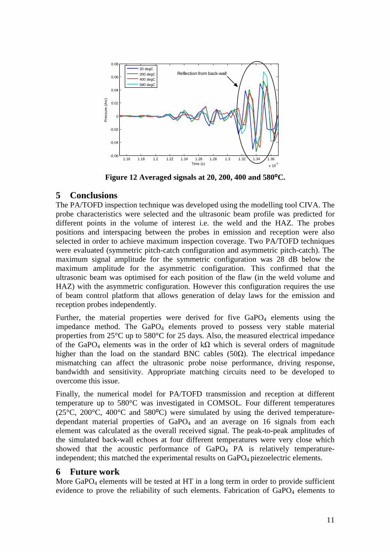
After implementing the time delay on the receiver PA, an average on these 16 signals from each element is calculated as the overall received signal. Four different temperatures (25°C, 200°C, 400°C and 580⁰C) are simulated by using the temperature-dependant material properties of GaPO4 as discussed in 3.2.2. The averaged received signals at Rx array at 25°C, 200°C, 400°C and 580⁰C are shown in Figure 12. A reflection with large amplitude is detected at around 13.4µs for each temperature, which is the reflection from the back-wall of the steel plate. The peak-to-peak amplitudes of the back-wall echo are 0.099, 0.1076, 0.9479 and 0.1100 (arbitrary unit) at 20⁰C, 200⁰C, 400⁰C and 580⁰C respectively. The simulation results show that the acoustic performance of GaPO4 PA is relatively temperature-independent, which matches the experimental results discussed in 3.2.2.
10
1.16 1.18 1.2 1.22 1.24 1.26 1.28 1.3 1.32 1.34 1.36
x 10-5
-0.06
-0.04
-0.02
0
0.02
0.04
0.06
0.08
Time (s)
Pre
ssur
e (A
rc)
20 degC200 degC400 degC580 degC
Reflection from back-wall
Figure 12 Averaged signals at 20, 200, 400 and 580⁰C.
5 Conclusions The PA/TOFD inspection technique was developed using the modelling tool CIVA. The probe characteristics were selected and the ultrasonic beam profile was predicted for different points in the volume of interest i.e. the weld and the HAZ. The probes positions and interspacing between the probes in emission and reception were also selected in order to achieve maximum inspection coverage. Two PA/TOFD techniques were evaluated (symmetric pitch-catch configuration and asymmetric pitch-catch). The maximum signal amplitude for the symmetric configuration was 28 dB below the maximum amplitude for the asymmetric configuration. This confirmed that the ultrasonic beam was optimised for each position of the flaw (in the weld volume and HAZ) with the asymmetric configuration. However this configuration requires the use of beam control platform that allows generation of delay laws for the emission and reception probes independently.
Further, the material properties were derived for five GaPO4 elements using the impedance method. The GaPO4 elements proved to possess very stable material properties from 25°C up to 580°C for 25 days. Also, the measured electrical impedance of the GaPO4 elements was in the order of kΩ which is several orders of magnitude higher than the load on the standard BNC cables (50Ω). The electrical impedance mismatching can affect the ultrasonic probe noise performance, driving response, bandwidth and sensitivity. Appropriate matching circuits need to be developed to overcome this issue.
Finally, the numerical model for PA/TOFD transmission and reception at different temperature up to 580°C was investigated in COMSOL. Four different temperatures (25°C, 200°C, 400°C and 580⁰C) were simulated by using the derived temperature-dependant material properties of GaPO4 and an average on 16 signals from each element was calculated as the overall received signal. The peak-to-peak amplitudes of the simulated back-wall echoes at four different temperatures were very close which showed that the acoustic performance of GaPO4 PA is relatively temperature-independent; this matched the experimental results on GaPO4 piezoelectric elements.
6 Future work More GaPO4 elements will be tested at HT in a long term in order to provide sufficient evidence to prove the reliability of such elements. Fabrication of GaPO4 elements to
11

achieve higher frequencies up to 5 MHz to be able to detect smaller defects should be possible and will form part of future effort. Finally, PA probes will be built using GaPO4 elements and subjected to laboratory and field trials. In order to test defect detection resolution and performance of the prototype PA/TOFD probes, a testing procedure has been developed. The PA/TOFD probes will be tested on steel specimens with a range of crack sizes at high operating temperature. The results on this will be reported once the probes are manufactured.
7 Acknowledgements This research has received funding from the European Commission through the FP7 Programme (FP7-SME-2013-1) under the grant agreement no. 605267, as part of a collaborative project “HotPhasedArray”. See project website: http://www.hotphasedarray.eu/project for more information. “HotPhasedArray” is collaboration between the following organisations: iKnowHow Informatics, CeramTec, InnoTecUK, Brunel University, Enkon, Vermon, Tecnitest Ingenieros and INETEC.
References [1] FP7 Project: “High Temperature Pipe Structural Health Monitoring System utilising PA
probes on TOFD configuration” (“HotPhasedArray”). Grant Agree. No 605267, 2013. [2] M. W. Hooker: “Properties of PZT-Based Piezoelectric Ceramics Between -150 and
250°C”. NASA / CR- 1998-208708, 1998. [3] D. Damjanovic: “Materials for high-temperature piezoelectric transducers”. Curr. Opin.
Solid State Mater. Sci., Vol 3, Pg 469–473, 1998. [4] S. Zhang and F. Yu: “Piezoelectric Materials for High Temperature Sensors”. J. Am.
Ceram. Soc., Vol 94, Pg 3153-3170, 2011. [5] P. Krempl: "Quartz Homeotypic Gallium-Orthophosphate – A New High Tech Piezoelectric
Material". IEEE Proc., UT Symp., Pg 949-954, France, 1994. [6] Active European Standard: “Piezoelectric properties of ceramic materials and components –
Part 2: Methods of measurement – Low power”. EN 50324-2:2002. [7] D. J. Abson and J. S. Rothwell: “Review of type IV cracking of weldments in 9-12% Cr
Creep strength enhanced ferritic steels”. International Materials Reviews, Vol 58, No 8, Pg 437-473, November 2013.
[8] C. Nageswaran and C. Bird: “Evaluation of the phased array transmit-receive longitudinal and time-of-flight diffraction techniques for inspection of a dissimilar weld”. Insight Vol 50 No 12, December 2008.
[9] Shantou Institute of Ultrasonic Instruments (SIUI) Co., Ltd: “Phased Array Probes and Wedges”. Available online at: file:///C:/Users/PoolUser/Downloads/Phased_Array_Probe_5.pdf. Accessed on: 06/07/2015
[10] W.P. Mason and H. Jaffe: “Methods for Measuring Piezoelectric, Elastic, and Dielectric Coefficients of Crystals and Ceramics”. Proc. IRE, Vol 42, No 6, Pg 1731-1737, 1954.
[11] Piezocryst Advanced Sensorics GMBH: “GaPO4-Resonators”. GaPO4 Material Datasheet.
[12] Keysight Technologies: “16334A Test Fixture (Tweezers Contacts)”. Available online at: http://www.keysight.com. Accessed on 13/04/2015.
[13] S. Sherrit, X. Bao, Y. Bar-Cohen and Z. Chang: "Resonance Analysis of High Temperature Piezoelectric Materials for Actuation and Sensing". San Diego, CA, SPIE Vol 5387, 2004.
12