Development of neural networks chip generating driving ...
6
Vol:.(1234567890) Artificial Life and Robotics (2021) 26:222–227 https://doi.org/10.1007/s10015-020-00669-5 1 3 ORIGINAL ARTICLE Development of neural networks chip generating driving waveform for electrostatic motor Takuro Sasaki 1 · Mika Kurosawa 1 · Yu Usami 1 · Shinya Kato 1 · Arisa Sakaki 1 · Yuki Takei 1 · Minami Kaneko 1 · Fumio Uchikoba 1 · Ken Saito 1 Received: 15 April 2020 / Accepted: 14 November 2020 / Published online: 3 January 2021 © The Author(s) 2021 Abstract The authors are studying hardware neural networks (HNN) to control the locomotion of the microrobot. The neural networks chip is the integrated circuit chip of the HNN. We proposed the electrostatic motor that is the new actuator of the microrobot in our previous research. The electrostatic motor used the waveform generator to generate the driving waveform. In this paper, the authors will propose the driving circuit using neural networks chip. The cell body model is the basic component of the neural networks chip that outputs 3 MHz frequency of electrical oscillated pulse waveform. Therefore, large capacitors need to connect outside of the neural networks chip to generate the low-frequency driving waveform. The proposal neural networks chip generates a long delay without using large capacitors. In addition, the neural networks chip generated a two-phase anti- phase synchronized waveform by incorporating a mechanism for adjusting synaptic weight. As a result, the proposal neural networks chip can generate the electrostatic motor’s driving waveform with variable frequency. The frequency of the driving waveform could vary from 40 to 126 Hz. Keywords Electrostatic motor · Hardware neural networks · Integrated circuit · MEMS · Microrobot 1 Introduction Insects have an excellent function. Although insects are small bodies, they perform external recognition through vision and touch. In addition, insects respond to the exter- nal environment with excellent control. Insects have a brain, muscles, sensory organs, and energy sources in small bodies. If the autonomous robots need to be small as insects, each component has to miniaturize. The microrobots are expected to search for a small place where people cannot enter. The centimeter-sized robot "HAMR" developed by Harvard Uni- versity is equipped with a control circuit and a power supply to achieve independent walking [1]. In addition, the millim- eter-sized robot developed by the University of Maryland has successfully walked using an external magnetic field [2]. However, miniaturization of a power supply, sensors, a control circuit, and actuators are a difficult subject [3]. This work was presented in part at the 25th International Symposium on Artificial Life and Robotics (Beppu, Oita, January 22–24, 2020). * Ken Saito [email protected] Takuro Sasaki [email protected] Mika Kurosawa [email protected] Yu Usami [email protected] Shinya Kato [email protected] Arisa Sakaki [email protected] Yuki Takei [email protected] Minami Kaneko [email protected] Fumio Uchikoba [email protected] 1 Nihon University, 7-24-1 Narashinodai, Funabashi, Chiba 274-8501, Japan
Transcript of Development of neural networks chip generating driving ...

Vol:.(1234567890)
Artificial Life and Robotics (2021) 26:222–227https://doi.org/10.1007/s10015-020-00669-5
1 3
ORIGINAL ARTICLE
Development of neural networks chip generating driving waveform for electrostatic motor
Takuro Sasaki1 · Mika Kurosawa1 · Yu Usami1 · Shinya Kato1 · Arisa Sakaki1 · Yuki Takei1 · Minami Kaneko1 · Fumio Uchikoba1 · Ken Saito1
Received: 15 April 2020 / Accepted: 14 November 2020 / Published online: 3 January 2021 © The Author(s) 2021
AbstractThe authors are studying hardware neural networks (HNN) to control the locomotion of the microrobot. The neural networks chip is the integrated circuit chip of the HNN. We proposed the electrostatic motor that is the new actuator of the microrobot in our previous research. The electrostatic motor used the waveform generator to generate the driving waveform. In this paper, the authors will propose the driving circuit using neural networks chip. The cell body model is the basic component of the neural networks chip that outputs 3 MHz frequency of electrical oscillated pulse waveform. Therefore, large capacitors need to connect outside of the neural networks chip to generate the low-frequency driving waveform. The proposal neural networks chip generates a long delay without using large capacitors. In addition, the neural networks chip generated a two-phase anti-phase synchronized waveform by incorporating a mechanism for adjusting synaptic weight. As a result, the proposal neural networks chip can generate the electrostatic motor’s driving waveform with variable frequency. The frequency of the driving waveform could vary from 40 to 126 Hz.
Keywords Electrostatic motor · Hardware neural networks · Integrated circuit · MEMS · Microrobot
1 Introduction
Insects have an excellent function. Although insects are small bodies, they perform external recognition through vision and touch. In addition, insects respond to the exter-nal environment with excellent control. Insects have a brain, muscles, sensory organs, and energy sources in small bodies.
If the autonomous robots need to be small as insects, each component has to miniaturize. The microrobots are expected to search for a small place where people cannot enter. The centimeter-sized robot "HAMR" developed by Harvard Uni-versity is equipped with a control circuit and a power supply to achieve independent walking [1]. In addition, the millim-eter-sized robot developed by the University of Maryland has successfully walked using an external magnetic field [2]. However, miniaturization of a power supply, sensors, a control circuit, and actuators are a difficult subject [3].
This work was presented in part at the 25th International Symposium on Artificial Life and Robotics (Beppu, Oita, January 22–24, 2020).
* Ken Saito [email protected]
Takuro Sasaki [email protected]
Mika Kurosawa [email protected]
Yu Usami [email protected]
Shinya Kato [email protected]
Arisa Sakaki [email protected]
Yuki Takei [email protected]
Minami Kaneko [email protected]
Fumio Uchikoba [email protected]
1 Nihon University, 7-24-1 Narashinodai, Funabashi, Chiba 274-8501, Japan

223Artificial Life and Robotics (2021) 26:222–227
1 3
Programming control by microcontrollers is the dominant system for robot control. On the other hand, insects have excellent sensory information processing and body control, enabling them to adapt to various environments despite their small size [4]. Therefore, research on applying the control method of biological neural networks to robots is conducted [5]. Information processing methods that mimic living organisms have the potential to create simple and compact systems.
The authors are studying hardware neural networks (HNN) [6–10]. The neural networks chip and the body parts of the microrobot were both made by a silicon wafer. The neural networks chip can integrate directly into the body parts of the microrobot. The development of neural net-works chip has an advantage because microcontrollers need to mount on a circuit board.
Previously, our constructed microrobot system succeeded to perform walking using an external power supply [7]. The neural networks chip generates the gait pattern of the micro-robot. The neural networks chip is the integrated circuit chip of the HNN. A shape memory alloy (SMA) actuator is used for driving the legs of the microrobot. SMA actuator has a large generating force and is simple and easy to miniatur-ize. However, the power consumption was high. Therefore, we developed an electrostatic motor as a new actuator [11]. Replacing the SMA actuator with the electrostatic motor can achieve a low power consumption of 60 V drive. The micro-robot can also drive by solar cells. A variable frequency square waveform is required to drive the electrostatic motor. A waveform generator has been used to generate the driving waveform of the electrostatic motor. Therefore, we proposed HNN to generate the driving waveform of the electrostatic motor to miniaturize the microrobot system [12]. In the sim-ulation result, the HNN generated the driving waveform of the electrostatic motor. In addition, we fabricated the neural networks chip. The neural networks chip successfully gener-ated pulses with a variable frequency (around 50–100 Hz). However, the neural networks chip could not generate a two-phase waveform with anti-phase synchronization [13].
In this paper, the authors will propose the neural networks chip that introduced a variable inhibitory-synaptic model. The two-phase waveforms can synchronize as anti-phase by adjusting the synaptic weight. In addition, we will discuss the measuring result of the neural networks chip.
2 Microrobot system
2.1 Microrobot
Figure 1 shows our previously proposed microrobot system [7]. The external dimensions are 4.6 mm × 9.0 mm × 6.4 mm.
Each part of the robot was manufactured using micro-elec-tro-mechanical systems technology. The SMA actuator drives the microrobot. The neural networks chip mounted on the robot can generate a gait pattern of the microrobot. The neural networks chip realizes miniaturization and weight reduction of the microrobot.
2.2 Electrostatic motor
Figure 2 shows our previously proposed electrostatic motor [8]. The size of the electrostatic motor was 2.2 mm × 2.5 mm. The electrostatic motor consists of two pairs of electrostatic actuators, a central shuttle, arms, sub-springs, a main-spring, and three-electrode pads, VD1, VD2, GND. The arms transmit the force of the electrostatic actuators. The electrostatic motor produces linear motion of the shuttle by energizing the electrodes. Sub-springs and main-spring return the shuttle to the primary position. The electrostatic motor outputs more than 1.3 mN that is suitable to actuate the microrobot’s legs.
Fig. 1 Microrobot system [7]
Fig. 2 Electrostatic motor [11]

224 Artificial Life and Robotics (2021) 26:222–227
1 3
Figure 3 shows a circuit diagram of the driving cir-cuit of the electrostatic motor. The circuit parameters are R1 = R2 = 2.2 MΩ, VCC = 60 V.
Figure 4 shows the driving waveform of the electro-static motor (VD1, VD2). The driving waveform has a pulse width of 7.5 ms, a pulse period of 10 ms, and an amplitude of 60 V. The driving waveform is generated by switching the transistor using a waveform generator. In Fig. 4, VWG1 and VWG2 are waveforms generated by the waveform gen-erator. The authors will replace the waveform generator with the neural networks chip in this paper.
2.3 Previous neural networks chip
Previously, we have shown that the neural networks chip can generate the drive waveform of the electrostatic motor shown in Fig. 4. using HSPICE simulations [12]. However, the fab-ricated neural networks chip’s measured results could not perform the two-phase anti-phase synchronized waveform. The reason is the synaptic model that synchronizes the two anti-phase outputs did not work correctly due to parasitic capacitance [13]. Therefore, in this paper, we fabricated a neural networks chip with an additional mechanism to change the synaptic model’s weight. The following sections provide details.
3 Neural networks chip
Figure 5 shows the schematic diagram of the constructed neural networks chip. The neural networks chip consists of four elements: the cell body model, excitatory-synaptic model, inhibitory-synaptic model, and variable inhibitory-synaptic model. Each component of the neural networks chip is described in Sect. 3.1.
Figure 6 shows the circuit diagram of the constructed neural networks chip. The circuit parameter is as follows. MOSFET: Max = W/L = 1.2 μm/8.5 μm, Mbx = 1.2 μm/10 μm, Mcx, Mdx = 10 μm/1.2 μm, Mex, Mfx, Mgx, Mhx, Mix, Mjx, Mlz, MV11, MV21, MV31, MV41, MV51, MV12, MV22, MV32, MV42, MV52 = 10 μm/10 μm, Mky = 2 μm/10 μm, MV61, MV62 = 10 μm/20 μm, capacitor: CGx = 1 pF, CMx = 0.1 pF, CSx = 8 pF, Power-supply voltage: VA = 3.43 V, VDD = 3.36 V, VAS = 0.80 V, Vint = 1.90 V, VW = 1.95 V (x = 1, 11, 12, 2, 21, and 22, y = 1, 11, 2, and 21, z = 11, 12, 21, and 22).
3.1 Hardware neuron model
3.1.1 Cell body model
In Fig. 6, "Self-OSC 1, Self-OSC 2, S11, S12, S21, and S22" shows the cell body model. The circuit consists of capaci-tors: CGx, CMx, MOSFET: Max, Mbx, Mcx, Mdx, voltage source: VA, VAS, VDD. The cell body model is an oscillation circuit that outputs pulses. The cell body model can switch between "self-excited oscillating mode" and "separately-excited oscillation mode" by varying the voltage source VA. A self-oscillating cell body model oscillates at 3 MHz. The cell body model switches to separately-excited oscilla-tion mode by lowering VA to 0.5–1.5 V. The power supply voltage VA of the separately-excited oscillation cell body model indicated as VAS. The separately excited oscillation cell body model oscillates pulses according to the oscilla-tion of other cell body models.
Fig. 3 Circuit diagram of driving circuit [11]
Fig. 4 Driving waveform of electrostatic motor
Fig. 5 Schematic diagram of the neural networks chip

225Artificial Life and Robotics (2021) 26:222–227
1 3
3.1.2 Synaptic model
The synaptic model mimics the characteristics of the biolog-ical synapse. Synapse is a connection part between the cell body. The synaptic model consists of MOSFET: Mex, Mfx, Mgx, Mhx, Mix, Mjx, Mky, Mlz, capacitor: CSx, voltage source: VDD, Vint. In Fig. 6, "iE" is transmitted as an output signal by an excitatory-synaptic model to the post-cell body model. By connecting the excitatory-synaptic model, the pre-cell body model excites the post-cell body model. Therefore, both cell body models will oscillate with in-phase synchronization. On the other hand, "iI" is transmitted as an output signal by the inhibitory-synaptic model to the post-cell body model. The inhibitory-synaptic model inhibits the oscillation of the post-cell body model. Therefore, both cell body mod-els will oscillate with anti-phase synchronization. In Fig. 6, green dotted line shows the circuit diagram of the variable inhibitory-synaptic model. The variable inhibitory-synaptic model consists of MOSFET: MV1 (MV11, MV12), MV2 (MV21, MV22), MV3 (MV31, MV32), MV4 (MV41, MV42), MV5 (MV51, MV52), MV6 (MV61, MV62), capacitor: CVS (CVS1, CVS2), volt-age source: VDD, VW. The variable inhibitory-synaptic model has the same function as the synaptic model concerning the function to inhibit. The variable inhibitory-synaptic model can vary the synaptic weight by varying the voltage VW.
3.2 Mechanism of the hardware neural networks
If the self-oscillating cell body model (Self-OSC 1) is not connected with the other cell body model, the Self-OSC 1 oscillates at 3.0 MHz. The separately-excited oscilla-tion cell body model S11 and S12 are the delay circuit. The delay mechanism is as follows.
1. Self-OSC 1 oscillates a pulse.2. The pulse of Self-OSC 1 excites the S11.3. S11 oscillates a pulse.4. The pulse of S11 inhibits the Self-OSC 1. It also excites
the S12.5. S12 oscillates a pulse.6. The pulse of S12 inhibits the Self-OSC 1.
As a result, Self-OSC 1 could not oscillate a pulse dur-ing the inhabitation from S11 and S12.
Figure 7 shows an example of a generated waveform of neural networks chip. Figure 7 shows that the mechanism worked, the pulse period increased and the pulse width increased. In addition, S11 and S21 inhibit Self-OSC 1 and Self-OSC 2, respectively. Thus, the output of HNN VNN1 and VNN2 will be an anti-phase waveform.
Fig. 6 Circuit diagram of the neural networks chip
226 Artificial Life and Robotics (2021) 26:222–227
1 3
3.3 Layout
Figure 8 shows the photograph of the fabricated neural net-works. A red dotted line indicates the constructed HNN, where the other part is the test element. An IC chip’s size is 2.5 × 2.5 mm. 14 electrode pads used as VA, VAS, VDD, Vint, VW, VNN1 (output 1), VNN2 (output 2), and GND for the cre-ated network part.
4 Measurement result
Figure 9 shows the example of the generated waveform of neural networks chip. The voltage of the circuit is as follows. VA = 3.43 V, VAS = 0.80 V, VDD = 3.36 V, V int = 1.90 V, VW = 1.95 V. Both of the waveform
frequencies are 65 Hz. As shown in Fig. 9., the neural net-works chip output a two-phase waveform with anti-phase synchronization.
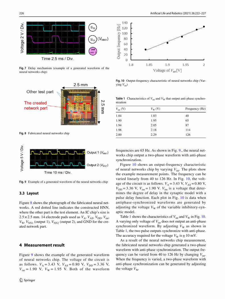
Figure 10 shows an output-frequency characteristic of neural networks chip by varying Vint. The plots show the example measurement points. The frequency can be varied linearly from 40 to 126 Hz. In Fig. 10, the volt-age of the circuit is as follows. VA = 3.43 V, VAS = 0.80 V, VDD = 3.36 V, Vint = 1.90 V. Vint is a voltage that deter-mines the degree of delay in the synaptic model with a pulse delay function. Each plot in Fig. 10 is data when antiphase-synchronized waveforms are generated by adjusting the voltage VW of the variable inhibitory-syn-aptic model.
Table 1 shows the characteristics of Vint and VW in Fig. 10. A varying only voltage of Vint does not output an anti-phase synchronized waveform. By adjusting VW as shown in Table 1, the two pulse outputs synchronize with anti-phase. The accuracy required for the voltage VW is ± 10 mV.
As a result of the neural networks chip measurement, the fabricated neural networks chip generated a two-phase waveform with anti-phase synchronization. The output fre-quency can be varied from 40 to 126 Hz by changing Vint. When the frequency is varied, a two-phase waveform with anti-phase synchronization can be generated by adjusting the voltage VW.
Fig. 7 Delay mechanism (example of a generated waveform of the neural networks chip)
Fig. 8 Fabricated neural networks chip
Fig. 9 Example of a generated waveform of the neural networks chip
Fig. 10 Output-frequency characteristic of neural networks chip (Var-ying Vint)
Table 1 Characteristics of Vint and VW that output anti-phase synchro-nization
Vint (V) VW (V) Frequency (Hz)
1.84 1.83 401.90 1.95 651.94 2.05 871.98 2.18 1142.00 2.29 126

227Artificial Life and Robotics (2021) 26:222–227
1 3
5 Conclusion
In this paper, the authors developed the neural networks chip that incorporates a mechanism to adjust the synaptic weight. As a result, the proposal neural networks chip generated the electrostatic motor’s driving waveform with variable fre-quency. The frequency of the driving waveform could vary from 40 to 126 Hz.
In the future, we will experiment with driving the electro-static motor using the neural networks chip. In addition, we will propose the microrobot system using the electrostatic motor.
Acknowledgements This work was supported by JSPS KAKENHI Grant Number JP18K04060. In addition, the part of this research sup-ported by Research Institute of Science and Technology Nihon Univer-sity College of Science and Technology Leading Research Promotion Grant. The fabrication of the microrobot was supported by Research Center for Micro Functional Devices. The VLSI chip (Fig. 1) in this study has been fabricated by Digian Technology, Inc. This work is sup-ported by VLSI Design and Education Center (VDEC), the University of Tokyo in collaboration with Synopsys, Inc., Cadence Design Sys-tems, Inc. and Mentor Graphics, Inc. The VLSI chip in this study has been fabricated in the chip fabrication program of VLSI Design and Education Center (VDEC), the University of Tokyo in collaboration with On-Semiconductor Niigata, and Toppan Printing Corporation. A part of creating HNN got an idea from Katsutoshi Saeki. Fabrication of the inchworm motors was supported by the UC Berkeley Marvell Nanofabrication Laboratory. The authors would like to acknowledge the Berkeley Sensor and Actuator Center and the UC Berkeley Swarm Lab for their continued support. In addition, we appreciated to the Nihon University Robotics Society (NUROS).
Open Access This article is licensed under a Creative Commons Attri-bution 4.0 International License, which permits use, sharing, adapta-tion, distribution and reproduction in any medium or format, as long as you give appropriate credit to the original author(s) and the source, provide a link to the Creative Commons licence, and indicate if changes were made. The images or other third party material in this article are included in the article’s Creative Commons licence, unless indicated otherwise in a credit line to the material. If material is not included in the article’s Creative Commons licence and your intended use is not permitted by statutory regulation or exceeds the permitted use, you will need to obtain permission directly from the copyright holder. To view a copy of this licence, visit http://creat iveco mmons .org/licen ses/by/4.0/.
References
1. Baisch T, Wood RJ (2013) Pop-up assembly of a quadrupedal ambulatory microrobot. In: IEEE/RSJ international conference on intelligent robots and systems (IROS) November 3–7, Tokyo
2. Vogtmann D, Pierre RS, Bergbreiter S (2017) A 25 mg magneti-cally actuated microrobot walking at > 5 body lengths/sec. In: IEEE 30th international conference on micro electro mechanical systems (MEMS), January 22–26, 2017, pp 179–182
3. Higuchi T (2002) Prospect of micro actuators. J Jpn Soc Precis Eng 68–5:629–632
4. Kanzaki R (2005) Nervous system and adaptive behavior in insects. J Robot Soc Japan 23(1):27–31
5. Nakada K, Asai T, Amemiya Y (2003) An analog CMOS central pattern generator for interlimb coordination in quadruped locomo-tion. IEEE Trans Neural Netw 14:1356–1365
6. Kurosawa M, Sasaki T, Usami Y et al (2020) Neural networks integrated circuit with switchable gait pattern for insect-type microrobot. In: The twenty-fifth international symposium on arti-ficial life and robotics 2020 (AROB 25th 2020), January 22–24 2020, Beppu, pp 876–880
7. Kawamura S, Tanaka D, Tanaka T et al (2018) Neural networks IC controlled multi-legged walking MEMS robot with independent leg mechanism. Artif Life Robot 23(3):380–386
8. Someya K, Shinozaki H, Sekine Y (1999) Pulse type hardware chaotic neuron model and its bifurcation phenomena. Neural Netw 12:153–161
9. Saito K, Takato M, Sekine Y (2012) Biomimetics micro robot with active hardware neural networks locomotion control and insect-like switching behaviour. In: Proceedings of the 2009 international joint conference on neural networks, Atlanta, pp 2748–2755
10. Saeki K, Nihei D, Tatebe T, Sekine Y (2014) IC implementation of an interstitial cell-based CPG model. In: Analog integr circ sig process, pp 551–559
11. Saito K, D. S. Contreras, Takeshiro Y et al (2018) Study on silicon device of microrobot system for heterogeneous integration. In: International conference on electronics packaging and iMAPS all Asia conference (ICEP-IAAC), 17–21 April 2018, Mie, Japan
12. Sasaki T, Kurosawa M, Ohara M et al (2020) Development of hardware neural networks generating driving waveform for elec-trostatic actuator. Artif Life Robot 32(3):446–452
13. Sasaki T, Kurosawa M, Ohara M et al (2019) Development of micro brain chip for driving electrostatic motor. In: Annual con-ference of electronics, information and systems society, IEE of Japan, September 4–7 2019, Okinawa, pp 958–963
Publisher’s Note Springer Nature remains neutral with regard to jurisdictional claims in published maps and institutional affiliations.