Development of More Efficient Cold-Formed Steel Channel...
14
This is a repository copy of Development of More Efficient Cold-Formed Steel Channel Sections in Bending. White Rose Research Online URL for this paper: http://eprints.whiterose.ac.uk/93111/ Version: Published Version Article: Ye, J., Hajirasouliha, I., Becque, J. et al. (1 more author) (2015) Development of More Efficient Cold-Formed Steel Channel Sections in Bending. Thin-Walled Structures, 101. pp. 1-13. ISSN 0263-8231 https://doi.org/10.1016/j.tws.2015.12.021 [email protected] https://eprints.whiterose.ac.uk/ Reuse This article is distributed under the terms of the Creative Commons Attribution (CC BY) licence. This licence allows you to distribute, remix, tweak, and build upon the work, even commercially, as long as you credit the authors for the original work. More information and the full terms of the licence here: https://creativecommons.org/licenses/ Takedown If you consider content in White Rose Research Online to be in breach of UK law, please notify us by emailing [email protected] including the URL of the record and the reason for the withdrawal request.
Transcript of Development of More Efficient Cold-Formed Steel Channel...
This is a repository copy of Development of More Efficient Cold-Formed Steel Channel Sections in Bending.
White Rose Research Online URL for this paper:http://eprints.whiterose.ac.uk/93111/
Version: Published Version
Article:
Ye, J., Hajirasouliha, I., Becque, J. et al. (1 more author) (2015) Development of More Efficient Cold-Formed Steel Channel Sections in Bending. Thin-Walled Structures, 101. pp. 1-13. ISSN 0263-8231
https://doi.org/10.1016/j.tws.2015.12.021
[email protected]://eprints.whiterose.ac.uk/
Reuse
This article is distributed under the terms of the Creative Commons Attribution (CC BY) licence. This licence allows you to distribute, remix, tweak, and build upon the work, even commercially, as long as you credit the authors for the original work. More information and the full terms of the licence here: https://creativecommons.org/licenses/
Takedown
If you consider content in White Rose Research Online to be in breach of UK law, please notify us by emailing [email protected] including the URL of the record and the reason for the withdrawal request.

Full length article
Development of more efficient cold-formed steel channel sections
in bending
Jun Ye n, Iman Hajirasouliha, Jurgen Becque, Kypros Pilakoutas
Department of Civil and Structural Engineering, The University of Sheffield, Sheffield, UK
a r t i c l e i n f o
Article history:
Received 19 November 2015
Received in revised form
12 December 2015
Accepted 17 December 2015
Available online 31 December 2015
Keywords:
Optimisation
Cold-formed steel
Effective width method
Finite element analysis
Flexural strength
a b s t r a c t
Cold-formed steel (CFS) cross-sections can be optimised to increase their load carrying capacity, leading
to more efficient and economical structural systems. This paper aims to provide a methodology that
would enable the development of optimised CFS beam sections with maximum flexural strength for
practical applications. The optimised sections are designed to comply with the Eurocode 3 (EC3) geo-
metrical requirements as well as with a number of manufacturing and practical constraints. The flexural
strengths of the sections are determined based on the effective width method adopted in EC3, while the
optimisation process is performed using the Particle Swarm Optimisation (PSO) method. To allow for the
development of a new ‘folded-flange’ cross-section, the effective width method in EC3 is extended to
deal with the possible occurrence of multiple distortional buckling modes. In total, ten different CFS
channel cross-section prototypes are considered in the optimisation process. The flexural strengths of the
optimised sections are verified using detailed nonlinear finite element (FE) analysis. The results indicate
that the optimised folded-flange section provides a bending capacity which is up to 57% higher than
standard optimised shapes with the same amount of material.
& 2015 The Authors. Published by Elsevier Ltd. This is an open access article under the CC BY license
(http://creativecommons.org/licenses/by/4.0/).
1. Introduction
Cold-formed steel (CFS) cross-sections are used extensively in
the construction industry as secondary load-carrying members,
such as roof purlins and wall girts. In recent years, however, CFS
cross-sections are also increasingly being employed as primary
structural elements. For example, CFS framing systems are used in
low- to mid-rise multi-storey buildings [1] and CFS portal frames
are gaining popularity in single-storey industrial buildings with
short to intermediate spans [2,3]. In both cases, CFS members are
employed as the primary load-bearing members and consequently
have to meet increased demands in terms of span length and load-
carrying capacity. Compared to hot-rolled members, CFS thin-
walled members offer several advantages of economy and effi-
ciency, including a high strength for a light weight, a relatively
straightforward manufacturing process and an ease of transpor-
tation and erection. Above all, CFS sections offer flexibility and
versatility in producing a variety of cross-sectional shapes, which
are obtained by bending relatively thin metal sheets using either a
cold-rolling or a press-braking process at room temperature. Fig.1
illustrates this by showing a series of relatively complex com-
mercially available CFS sections and profiled sheets. The flexibility
of the manufacturing process in obtaining various shapes means
that there is a great potential for CFS sections to be optimised to
meet specific objectives, thereby bringing practical benefits to
both manufacturers and structural designers.
Due to their typically large flat width-to-thickness ratios, CFS
sections are inherently susceptible to local, distortional and global
buckling modes, resulting in a complex optimisation process.
Previous studies on the optimisation of CFS elements have mainly
been limited to varying the dimensions of standard cross-sections
such as lipped channel beams [4], channel columns with and
without lips [5,6] and hat, I- and Z- cross section CFS beams [7].
Taking the elastic buckling strength as an optimisation criterion,
Magnucki et al. [8,9] developed optimum CFS beams with a mono-
symmetrical open cross-section and sinusoidally corrugated flan-
ges, as well as optimum I-shaped sections with box-shaped flan-
ges. A CFS channel beam with closed hollow flanges was proposed
and optimised with respect to its member capacity by Magnucka-
Blandzi [10]. Analytical formulas were thereby developed to cal-
culate the local and global buckling strengths in a process to ob-
tain feasible solutions in a design space constrained by geometric
conditions. The results of their study indicated a better flexural
performance compared to the traditional lipped or plain channel
sections. More recently, CFS compression and bending members
[11,12] were optimised with respect to their capacity according to
EC3 [13] using Genetic Algorithms. The researchers investigated
the influence of the column length and the shift of the effective
Contents lists available at ScienceDirect
journal homepage: www.elsevier.com/locate/tws
Thin-Walled Structures
http://dx.doi.org/10.1016/j.tws.2015.12.021
0263-8231/& 2015 The Authors. Published by Elsevier Ltd. This is an open access article under the CC BY license (http://creativecommons.org/licenses/by/4.0/).
n Corresponding author.
E-mail address: [email protected] (J. Ye).
Thin-Walled Structures 101 (2016) 1–13

centroid, induced by local/distortional buckling, on the optimal
design solutions. The shapes of the cross-section were thereby
limited to the conventionally used lipped channels.
In order to obtain ‘global optimum’ solutions, research at Johns
Hopkins University and Griffith University was conducted on the
free form optimisation of CFS cross-sections without placing any
prior constraints on the shape of the cross-section. The finite strip
method (FSM) and the direct strength method (DSM [14]) were
thereby combined with Genetic Algorithms (GA) to obtain opti-
mum shapes for open CFS cross section columns [15–17]. While
this led to some innovative new geometries, the resulting cross-
sections were not ‘pre-qualified’ according to the DSM approach,
thus casting some doubt on the optimisation procedure. Ad-
ditionally, these studies did not consider any manufacturing or
construction constraints and, therefore, highly complex shapes
were obtained which cannot be deemed suitable for practical
applications due to a complex (or unfeasible) manufacturing pro-
cess and the obvious difficulty in connecting the cross-section to
other elements. Leng et al. [18] later advanced this work by in-
corporating some end-user constraints and by limiting the num-
bers of rolling passes in the manufacturing process. CFS columns
with different lengths were optimised and more practical shapes
were obtained, which, however, still did not meet the DSM pre-
qualification criteria.
Recent experimental and numerical research on CFS moment
resisting connections [19] at the University of Sheffield has de-
monstrated that CFS channel sections with curved flanges (Fig. 2a)
display a higher flange buckling load and also possess higher
strength, stiffness and ductility compared to channels with flat
flanges. However, this type of cross-section is difficult to connect
to a typical floor system, allowing just a point contact. Practically,
the curved flange can be substituted with a folded flange which
approximates it, as shown in Fig. 2(b). However, the EC3 guidelines
[13,20,21] do not provide a direct procedure for the design of such
cross-sections. In particular, there is a need to develop a design
procedure that can account for the multiple distortional buckling
modes which may occur in the folded-flange section. This study
aims to develop such a design methodology in order to subse-
quently use it to optimise the CFS folded-flange section. The effi-
ciency of the folded-flange beam section is investigated alongside
nine more conventional channel prototypes which are aimed at
investigating the effects of intermediate web stiffeners, return lips
and inclined lips. All sections are optimised by maximising the
cross-sectional flexural capacity for a given thickness and coil
width (equal to the total developed length of the cross-section). A
brief overview of the effective width method adopted in EC3 [13]
is first given in Section 2. This method is then extended to deal
with the presence of multiple distortional buckling modes in the
folded-flange cross-section. The particle swarm optimisation (PSO)
method, used to solve the optimisation problem, is described in
Section 3 and the optimum solutions are presented in Section 4.
The accuracy of the proposed design model and the efficiency of
the optimisation procedure are investigated through detailed
nonlinear FE modelling in Section 5. A comprehensive comparison
of the optimised results is provided in Section 6.
2. Design of CFS members based on EC3
The CFS sections to be optimised are evaluated according to the
cross-sectional strength and stability provisions in EN1993-1-3
(EC3) [13] accounting for both local and distortional buckling
modes. The “notional flat widths” [19] of the plate assemblies are
used to determine the cross-sectional properties, which are then
reduced by a factor (δ) to account for the influence of the rounded
corners. A brief description of the EC3 provisions for the design of
CFS members is provided in the following subsections.
2.1. Local buckling
In EC3, the effect of local buckling is considered through the
effective width concept. It recognises the fact that local buckling of
the plates constituting the cross-section has the effect of shifting
the load-bearing stresses towards the corner zones, in the process
Fig. 1. Examples of commercially available CFS sections with complex shapes.
Fig. 2. CFS beams with (a) curved flanges and (b) folded flanges.
Fig. 3. Local buckling mode of a folded-flange cross-section: (a) buckled shape, (b) effective area of the cross-section for local buckling, (c, d) web under stress gradient.
J. Ye et al. / Thin-Walled Structures 101 (2016) 1–132
reducing the effectiveness of the central parts in carrying com-
pressive stresses. The cross-section is consequently idealised as an
“effective cross-section”, shown in solid black line in Fig. 3(b). This
effective area is assumed to resist the full bending action applied
to the section. According to Eurocode 3, Part 1–5 [21], the effective
width of a (doubly supported) plate is given by:
⎛
⎝⎜
⎞
⎠⎟
λ
ψ
λ= −
( + )
( )
b
b
11
0.055 3
1
e
l l
λσ
=( )
fwith
2l
y
cr
( )σ
π=
− ( )
k Et
v band
12 1 3cr
2 2
2 2
where b and be are the total and the effective width of the plate,respectively. ψ = f f/2 1 is the stress ratio of the plate, as shown in
Fig.3(c) and (d). An equation similar to Eq. (1) is also provided for
outstand elements. The slenderness ratio for local buckling, λl,relates the material yield stress, fy, to the elastic local buckling
stress of the plate, σcr . In Eq. (3), v and E are the Poisson's ratio andthe Young’s modulus of the plate, respectively, and k is the
buckling factor calculated using Eurocode 3, Part 1–5 [21] based on
the boundary conditions and the stress ratio ψ . For a doubly
supported plate subjected to uniform compression k¼4, while for
an outstand element under uniform compression k¼0.43. The
Eurocode thus assumes, for the purpose of calculating scr, that
every plate element is simply supported along its fold-lines, ne-
glecting any interaction with adjacent plates. It is also worth
noting that, in principle, the Eurocode always calculates the ef-
fective cross-section, Weff , based on the yield stress, fy, while some
other design standards (e.g. the AISI [14] and AS/NZS [22] speci-
fications) use the stress at global buckling.
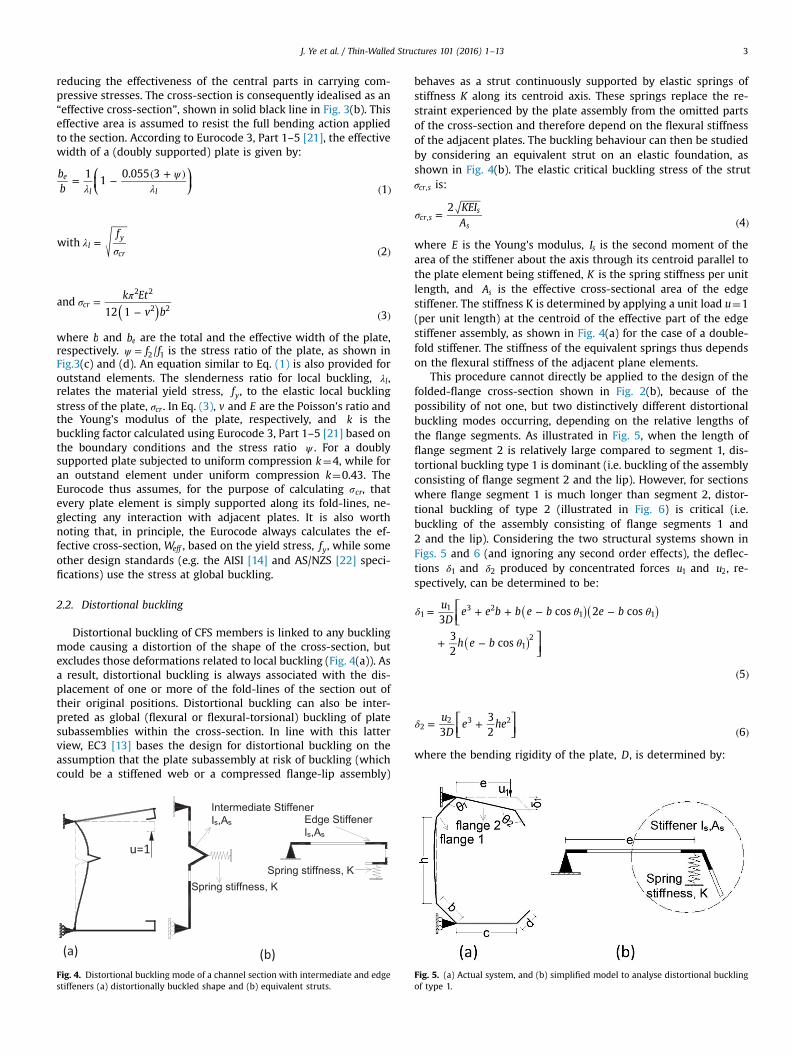
2.2. Distortional buckling
Distortional buckling of CFS members is linked to any buckling
mode causing a distortion of the shape of the cross-section, but
excludes those deformations related to local buckling (Fig. 4(a)). As
a result, distortional buckling is always associated with the dis-
placement of one or more of the fold-lines of the section out of
their original positions. Distortional buckling can also be inter-
preted as global (flexural or flexural-torsional) buckling of plate
subassemblies within the cross-section. In line with this latter
view, EC3 [13] bases the design for distortional buckling on the
assumption that the plate subassembly at risk of buckling (which
could be a stiffened web or a compressed flange-lip assembly)
behaves as a strut continuously supported by elastic springs of
stiffness K along its centroid axis. These springs replace the re-
straint experienced by the plate assembly from the omitted parts
of the cross-section and therefore depend on the flexural stiffness
of the adjacent plates. The buckling behaviour can then be studied
by considering an equivalent strut on an elastic foundation, as
shown in Fig. 4(b). The elastic critical buckling stress of the strut
σcr s, is:
σ =( )
KEI
A
2
4cr s
s
s,
where E is the Young's modulus, Is is the second moment of the
area of the stiffener about the axis through its centroid parallel to
the plate element being stiffened, K is the spring stiffness per unit
length, and As is the effective cross-sectional area of the edge
stiffener. The stiffness K is determined by applying a unit load u¼1
(per unit length) at the centroid of the effective part of the edge
stiffener assembly, as shown in Fig. 4(a) for the case of a double-
fold stiffener. The stiffness of the equivalent springs thus depends
on the flexural stiffness of the adjacent plane elements.
This procedure cannot directly be applied to the design of the
folded-flange cross-section shown in Fig. 2(b), because of the
possibility of not one, but two distinctively different distortional
buckling modes occurring, depending on the relative lengths of
the flange segments. As illustrated in Fig. 5, when the length of
flange segment 2 is relatively large compared to segment 1, dis-
tortional buckling type 1 is dominant (i.e. buckling of the assembly
consisting of flange segment 2 and the lip). However, for sections
where flange segment 1 is much longer than segment 2, distor-
tional buckling of type 2 (illustrated in Fig. 6) is critical (i.e.
buckling of the assembly consisting of flange segments 1 and
2 and the lip). Considering the two structural systems shown in
Figs. 5 and 6 (and ignoring any second order effects), the deflec-
tions δ1 and δ2 produced by concentrated forces u1 and u2, re-
spectively, can be determined to be:
⎡
⎣⎢
⎤
⎦⎥
( )( )
( )
δ θ θ
θ
= + + − −
+ −
( )
u
De e b b e b e b
h e b
3cos 2 cos
3
2cos
5
11 3 2
1 1
12
⎡
⎣⎢⎤
⎦⎥δ = +
( )
u
De he
3
3
2 62
2 3 2
where the bending rigidity of the plate, D, is determined by:
u=1
Edge Stiffener
Is,As
Spring stiffness, K
Spring stiffness, K
Intermediate Stiffener
Is,As
Fig. 4. Distortional buckling mode of a channel section with intermediate and edge
stiffeners (a) distortionally buckled shape and (b) equivalent struts.
Fig. 5. (a) Actual system, and (b) simplified model to analyse distortional buckling
of type 1.
J. Ye et al. / Thin-Walled Structures 101 (2016) 1–13 3
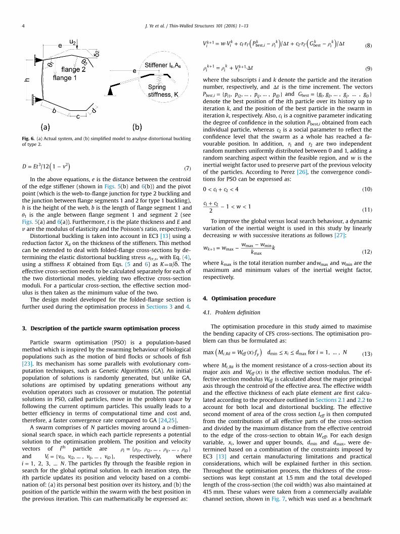
( )= − ( )D Et v/12 1 73 2
In the above equations, e is the distance between the centroid
of the edge stiffener (shown in Figs. 5(b) and 6(b)) and the pivot
point (which is the web-to-flange junction for type 2 buckling and
the junction between flange segments 1 and 2 for type 1 buckling),
h is the height of the web, b is the length of flange segment 1 and
θ1 is the angle between flange segment 1 and segment 2 (see
Figs. 5(a) and 6(a)). Furthermore, t is the plate thickness and E and
v are the modulus of elasticity and the Poisson’s ratio, respectively.
Distortional buckling is taken into account in EC3 [13] using a
reduction factor Xd on the thickness of the stiffeners. This method
can be extended to deal with folded-flange cross-sections by de-
termining the elastic distortional buckling stress σcr s, , with Eq. (4),
using a stiffness K obtained from Eqs. (5 and 6) as K¼u/δ. The
effective cross-section needs to be calculated separately for each of
the two distortional modes, yielding two effective cross-section
moduli. For a particular cross-section, the effective section mod-
ulus is then taken as the minimum value of the two.
The design model developed for the folded-flange section is
further used during the optimisation process in Sections 3 and 4.
3. Description of the particle swarm optimisation process
Particle swarm optimisation (PSO) is a population-based
method which is inspired by the swarming behaviour of biological
populations such as the motion of bird flocks or schools of fish
[23]. Its mechanism has some parallels with evolutionary com-
putation techniques, such as Genetic Algorithms (GA). An initial
population of solutions is randomly generated, but unlike GA,
solutions are optimised by updating generations without any
evolution operators such as crossover or mutation. The potential
solutions in PSO, called particles, move in the problem space by
following the current optimum particles. This usually leads to a
better efficiency in terms of computational time and cost and,
therefore, a faster convergence rate compared to GA [24,25].
A swarm comprises of N particles moving around a D-dimen-
sional search space, in which each particle represents a potential
solution to the optimisation problem. The position and velocity
vectors of ith particle are ρ ρ ρ ρ ρ= { }, , ... , , ... ,i i i ij iD1 2
and = { }V v v v v, , ... , , ... ,i i i ij iD1 2 , respectively, where
=i N1, 2, 3, ... . The particles fly through the feasible region in
search for the global optimal solution. In each iteration step, the
ith particle updates its position and velocity based on a combi-
nation of: (a) its personal best position over its history, and (b) the
position of the particle within the swarm with the best position in
the previous iteration. This can mathematically be expressed as:
( ) ( )ρ ρ= ⋅ + ⋅ ⋅ − Δ + ⋅ ⋅ − Δ ( )+V w V c r P t c r G t/ / 8i
kik
ik
ik k
ik1
1 1 best, 2 2 best
ρ ρ= + ⋅Δ ( )+ +V t 9i
kik
ik1 1
where the subscripts i and k denote the particle and the iteration
number, respectively, and Δt is the time increment. The vectors
= { }P p p p p, , ... , , ... ,best i i i ij iD, 1 2 and = { }G g g g g, , ... , , ... ,j Dbest 1 2
denote the best position of the ith particle over its history up to
iteration k, and the position of the best particle in the swarm in
iteration k, respectively. Also, c1 is a cognitive parameter indicating
the degree of confidence in the solution Pbest,i obtained from each
individual particle, whereas c2 is a social parameter to reflect the
confidence level that the swarm as a whole has reached a fa-
vourable position. In addition, r1 and r2 are two independent
random numbers uniformly distributed between 0 and 1, adding a
random searching aspect within the feasible region, and w is the
inertial weight factor used to preserve part of the previous velocity
of the particles. According to Perez [26], the convergence condi-
tions for PSO can be expressed as:
< + < ( )c c0 4 101 2
+− < <
( )
c cw
21 1
111 2
To improve the global versus local search behaviour, a dynamic
variation of the inertial weight is used in this study by linearly
decreasing w with successive iterations as follows [27]:
= −−
( )+w w
w w
kk
12k 1 max
max min
max
where kmax is the total iteration number andwmax and wmin are the
maximum and minimum values of the inertial weight factor,
respectively.
4. Optimisation procedure
4.1. Problem definition
The optimisation procedure in this study aimed to maximise
the bending capacity of CFS cross-sections. The optimisation pro-
blem can thus be formulated as:
( )= ( )⋅ ≤ ≤ = ( )M W x f d x d i Nmax for 1, ... , 13c Rd eff y i, min max
where Mc Rd, is the moment resistance of a cross-section about its
major axis and ( )W xeff is the effective section modulus. The ef-
fective section modulusWeff is calculated about the major principal
axis through the centroid of the effective area. The effective width
and the effective thickness of each plate element are first calcu-
lated according to the procedure outlined in Sections 2.1 and 2.2 to
account for both local and distortional buckling. The effective
second moment of area of the cross section Ieff is then computed
from the contributions of all effective parts of the cross-section
and divided by the maximum distance from the effective centroid
to the edge of the cross-section to obtain Weff. For each design
variable, xi, lower and upper bounds, dmin and dmax, were de-
termined based on a combination of the constraints imposed by
EC3 [13] and certain manufacturing limitations and practical
considerations, which will be explained further in this section.
Throughout the optimisation process, the thickness of the cross-
sections was kept constant at 1.5 mm and the total developed
length of the cross-section (the coil width) was also maintained at
415 mm. These values were taken from a commercially available
channel section, shown in Fig. 7, which was used as a benchmark
Fig. 6. (a) Actual system, and (b) simplified model to analyse distortional buckling
of type 2.
J. Ye et al. / Thin-Walled Structures 101 (2016) 1–134
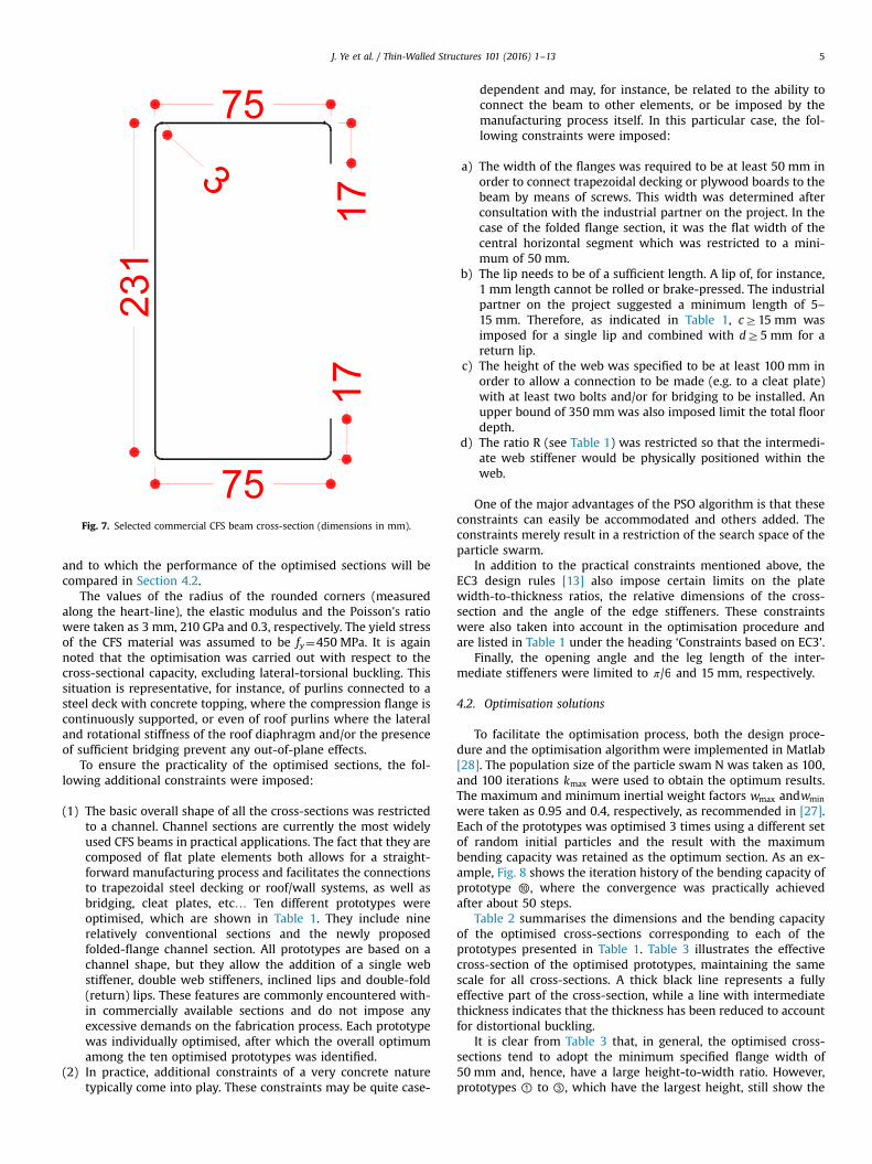
and to which the performance of the optimised sections will be
compared in Section 4.2.
The values of the radius of the rounded corners (measured
along the heart-line), the elastic modulus and the Poisson's ratio
were taken as 3 mm, 210 GPa and 0.3, respectively. The yield stress
of the CFS material was assumed to be fy¼450 MPa. It is again
noted that the optimisation was carried out with respect to the
cross-sectional capacity, excluding lateral-torsional buckling. This
situation is representative, for instance, of purlins connected to a
steel deck with concrete topping, where the compression flange is
continuously supported, or even of roof purlins where the lateral
and rotational stiffness of the roof diaphragm and/or the presence
of sufficient bridging prevent any out-of-plane effects.
To ensure the practicality of the optimised sections, the fol-
lowing additional constraints were imposed:
(1) The basic overall shape of all the cross-sections was restricted
to a channel. Channel sections are currently the most widely
used CFS beams in practical applications. The fact that they are
composed of flat plate elements both allows for a straight-
forward manufacturing process and facilitates the connections
to trapezoidal steel decking or roof/wall systems, as well as
bridging, cleat plates, etc… Ten different prototypes were
optimised, which are shown in Table 1. They include nine
relatively conventional sections and the newly proposed
folded-flange channel section. All prototypes are based on a
channel shape, but they allow the addition of a single web
stiffener, double web stiffeners, inclined lips and double-fold
(return) lips. These features are commonly encountered with-
in commercially available sections and do not impose any
excessive demands on the fabrication process. Each prototype
was individually optimised, after which the overall optimum
among the ten optimised prototypes was identified.
(2) In practice, additional constraints of a very concrete nature
typically come into play. These constraints may be quite case-
dependent and may, for instance, be related to the ability to
connect the beam to other elements, or be imposed by the
manufacturing process itself. In this particular case, the fol-
lowing constraints were imposed:
a) The width of the flanges was required to be at least 50 mm in
order to connect trapezoidal decking or plywood boards to the
beam by means of screws. This width was determined after
consultation with the industrial partner on the project. In the
case of the folded flange section, it was the flat width of the
central horizontal segment which was restricted to a mini-
mum of 50 mm.
b) The lip needs to be of a sufficient length. A lip of, for instance,
1 mm length cannot be rolled or brake-pressed. The industrial
partner on the project suggested a minimum length of 5–
15 mm. Therefore, as indicated in Table 1, cZ15 mm was
imposed for a single lip and combined with dZ5 mm for a
return lip.
c) The height of the web was specified to be at least 100 mm in
order to allow a connection to be made (e.g. to a cleat plate)
with at least two bolts and/or for bridging to be installed. An
upper bound of 350 mm was also imposed limit the total floor
depth.
d) The ratio R (see Table 1) was restricted so that the intermedi-
ate web stiffener would be physically positioned within the
web.
One of the major advantages of the PSO algorithm is that these
constraints can easily be accommodated and others added. The
constraints merely result in a restriction of the search space of the
particle swarm.
In addition to the practical constraints mentioned above, the
EC3 design rules [13] also impose certain limits on the plate
width-to-thickness ratios, the relative dimensions of the cross-
section and the angle of the edge stiffeners. These constraints
were also taken into account in the optimisation procedure and
are listed in Table 1 under the heading ‘Constraints based on EC3’.
Finally, the opening angle and the leg length of the inter-
mediate stiffeners were limited to π/6 and 15 mm, respectively.
4.2. Optimisation solutions
To facilitate the optimisation process, both the design proce-
dure and the optimisation algorithm were implemented in Matlab
[28]. The population size of the particle swam N was taken as 100,
and 100 iterations kmax were used to obtain the optimum results.
The maximum and minimum inertial weight factors wmax andwmin
were taken as 0.95 and 0.4, respectively, as recommended in [27].
Each of the prototypes was optimised 3 times using a different set
of random initial particles and the result with the maximum
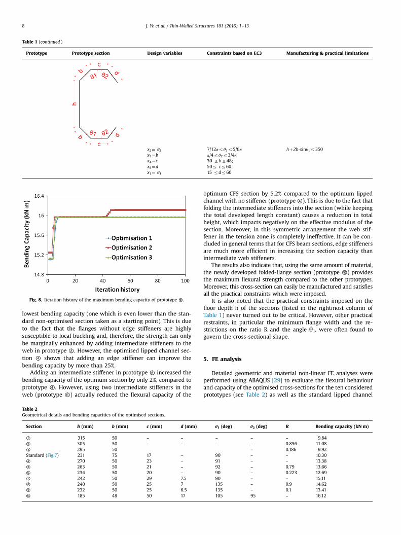
bending capacity was retained as the optimum section. As an ex-
ample, Fig. 8 shows the iteration history of the bending capacity of
prototype ⑩, where the convergence was practically achieved
after about 50 steps.
Table 2 summarises the dimensions and the bending capacity
of the optimised cross-sections corresponding to each of the
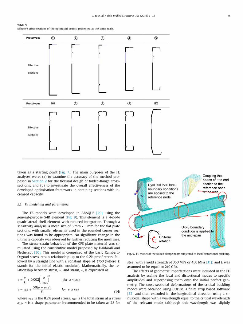
prototypes presented in Table 1. Table 3 illustrates the effective
cross-section of the optimised prototypes, maintaining the same
scale for all cross-sections. A thick black line represents a fully
effective part of the cross-section, while a line with intermediate
thickness indicates that the thickness has been reduced to account
for distortional buckling.
It is clear from Table 3 that, in general, the optimised cross-
sections tend to adopt the minimum specified flange width of
50 mm and, hence, have a large height-to-width ratio. However,
prototypes ① to ③, which have the largest height, still show the
75
17
17
75
23
13
Fig. 7. Selected commercial CFS beam cross-section (dimensions in mm).
J. Ye et al. / Thin-Walled Structures 101 (2016) 1–13 5
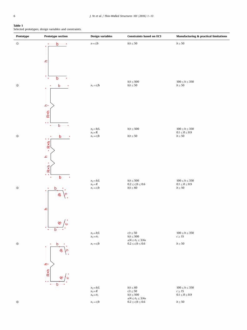
Table 1
Selected prototypes, design variables and constraints.
Prototype Prototype section Design variables Constraints based on EC3 Manufacturing & practical limitations
① x¼c/b b/tr50 bZ50
h/tr500 100rhr350
② x1¼c/b b/tr50 bZ50
x2¼b/L h/tr500 100rhr350
x3¼R 0.1rRr0.9
③ x1¼c/b b/tr50 bZ50
x2¼b/L h/tr500 100rhr350
x3¼R 0.2rc/br0.6 0.1rRr0.9
④ x1¼c/b b/tr60 bZ50
x2¼b/L c/tr50 100rhr350
x3¼θ1 h/tr500 cZ15
π/4rθ1r3/4π
⑤ x1¼c/b 0.2rc/br0.6 bZ50
x2¼b/L b/tr60 100rhr350
x3¼R c/tr50 cZ15
x4¼θ1 h/tr500 0.1rRr0.9
π/4rθ1r3/4π
⑥ x1¼c/b 0.2rc/br0.6 bZ50
J. Ye et al. / Thin-Walled Structures 101 (2016) 1–136
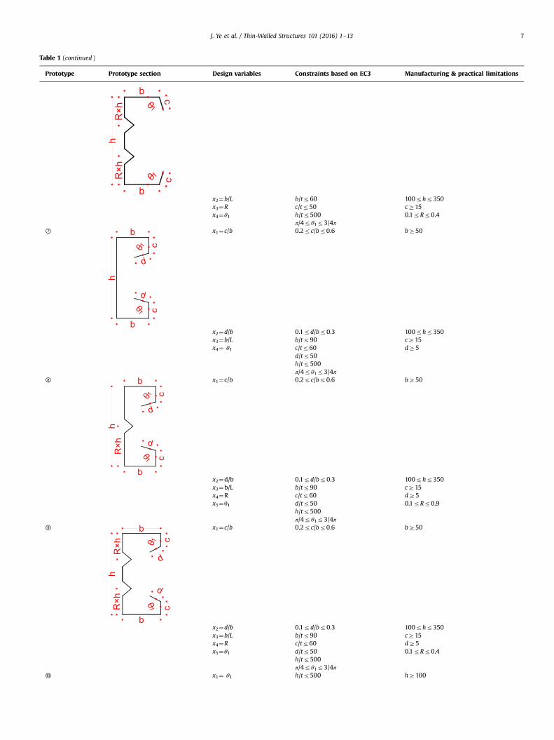
Table 1 (continued )
Prototype Prototype section Design variables Constraints based on EC3 Manufacturing & practical limitations
x2¼b/L b/tr60 100rhr350
x3¼R c/tr50 cZ15
x4¼θ1 h/tr500 0.1rRr0.4
π/4rθ1r3/4π
⑦ x1¼c/b 0.2rc/br0.6 bZ50
x2¼d/b 0.1rd/br0.3 100rhr350
x3¼b/L b/tr90 cZ15
x4¼ θ1 c/tr60 dZ5
d/tr50
h/tr500
π/4rθ1r3/4π
⑧ x1¼c/b 0.2rc/br0.6 bZ50
x2¼d/b 0.1rd/br0.3 100rhr350
x3¼b/L b/tr90 cZ15
x4¼R c/tr60 dZ5
x5¼θ1 d/tr50 0.1rRr0.9
h/tr500
π/4rθ1r3/4π
⑨ x1¼c/b 0.2rc/br0.6 bZ50
x2¼d/b 0.1rd/br0.3 100rhr350
x3¼b/L b/tr90 cZ15
x4¼R c/tr60 dZ5
x5¼θ1 d/tr50 0.1rRr0.4
h/tr500
π/4rθ1r3/4π
⑩ x1¼ θ1 h/tr500 hZ100
J. Ye et al. / Thin-Walled Structures 101 (2016) 1–13 7
lowest bending capacity (one which is even lower than the stan-
dard non-optimised section taken as a starting point). This is due
to the fact that the flanges without edge stiffeners are highly
susceptible to local buckling and, therefore, the strength can only
be marginally enhanced by adding intermediate stiffeners to the
web in prototype ③. However, the optimised lipped channel sec-
tion ④ shows that adding an edge stiffener can improve the
bending capacity by more than 25%.
Adding an intermediate stiffener in prototype ⑤ increased the
bending capacity of the optimum section by only 2%, compared to
prototype ④. However, using two intermediate stiffeners in the
web (prototype ⑥) actually reduced the flexural capacity of the
optimum CFS section by 5.2% compared to the optimum lipped
channel with no stiffener (prototype④). This is due to the fact that
folding the intermediate stiffeners into the section (while keeping
the total developed length constant) causes a reduction in total
height, which impacts negatively on the effective modulus of the
section. Moreover, in this symmetric arrangement the web stif-
fener in the tension zone is completely ineffective. It can be con-
cluded in general terms that for CFS beam sections, edge stiffeners
are much more efficient in increasing the section capacity than
intermediate web stiffeners.
The results also indicate that, using the same amount of material,
the newly developed folded-flange section (prototype ⑩) provides
the maximum flexural strength compared to the other prototypes.
Moreover, this cross-section can easily be manufactured and satisfies
all the practical constraints which were imposed.
It is also noted that the practical constraints imposed on the
floor depth h of the sections (listed in the rightmost column of
Table 1) never turned out to be critical. However, other practical
restraints, in particular the minimum flange width and the re-
strictions on the ratio R and the angle θ1, were often found to
govern the cross-sectional shape.
5. FE analysis
Detailed geometric and material non-linear FE analyses were
performed using ABAQUS [29] to evaluate the flexural behaviour
and capacity of the optimised cross-sections for the ten considered
prototypes (see Table 2) as well as the standard lipped channel
Table 1 (continued )
Prototype Prototype section Design variables Constraints based on EC3 Manufacturing & practical limitations
x2¼ θ2 7/12πrθ1r5/6π hþ2b-sinθ1r350
x3¼b π/4rθ2r3/4π
x4¼c 30 rbr48;
x5¼d 50r cr60;
x1¼ θ1 15 rdr60
Fig. 8. Iteration history of the maximum bending capacity of prototype ⑩.
Table 2
Geometrical details and bending capacities of the optimised sections.
Section h (mm) b (mm) c (mm) d (mm) θ1 (deg) θ2 (deg) R Bending capacity (kN m)
① 315 50 – – – – – 9.84
② 305 50 – – – – 0.856 11.08
③ 295 50 – 0.186 9.92
Standard (Fig.7) 231 75 17 – 90 – – 10.30
④ 270 50 23 – 91 – – 13.38
⑤ 263 50 21 – 92 – 0.79 13.66
⑥ 234 50 20 – 90 – 0.223 12.69
⑦ 242 50 29 7.5 90 – – 15.11
⑧ 240 50 25 7 135 – 0.9 14.62
⑨ 232 50 25 6.5 135 – 0.1 13.41
⑩ 185 48 50 17 105 95 – 16.12
J. Ye et al. / Thin-Walled Structures 101 (2016) 1–138
taken as a starting point (Fig. 7). The main purposes of the FE
analyses were: (a) to examine the accuracy of the method pro-
posed in Section 2 for the flexural design of folded-flange cross-
sections; and (b) to investigate the overall effectiveness of the
developed optimisation framework in obtaining sections with in-
creased capacity.
5.1. FE modelling and parameters
The FE models were developed in ABAQUS [29] using the
general-purpose S4R element (Fig. 9). This element is a 4-node
quadrilateral shell element with reduced integration. Through a
sensitivity analysis, a mesh size of 5 mm�5 mm for the flat plate
sections, with smaller elements used in the rounded corner sec-
tions was found to be appropriate. No significant change in the
ultimate capacity was observed by further reducing the mesh size.
The stress–strain behaviour of the CFS plate material was si-
mulated using the constitutive model proposed by Haidarali and
Nethercot [30]. This model is comprised of the basic Ramberg-
Osgood stress–strain relationship up to the 0.2% proof stress, fol-
lowed by a straight line with a constant slope of E/50 (where E
stands for the initial elastic modulus). Mathematically, the re-
lationship between stress, σ , and strain, ε, is expressed as:
⎛
⎝⎜
⎞
⎠⎟ε
σ σ
σσ σ
ε εσ σ
σ σ
= + ≤
= +( − )
≥( )
Efor
Efor
0.002
50
14
n
0.20.2
0.20.2
0.2
where σ0.2 is the 0.2% proof stress, ε0.2 is the total strain at a stress
σ0.2, n is a shape parameter (recommended to be taken as 28 for
steel with a yield strength of 350 MPa or 450 MPa [31]) and E was
assumed to be equal to 210 GPa.
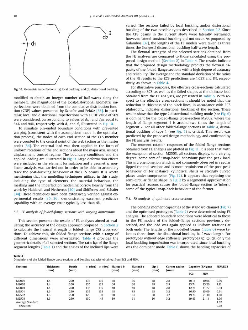
The effects of geometric imperfections were included in the FE
analysis by scaling the local and distortional modes to specific
amplitudes and superposing them onto the initial perfect geo-
metry. The cross-sectional deformations of the critical buckling
modes were obtained using CUFSM, a finite strip based software
[32] and then extruded in the longitudinal direction using a si-
nusoidal shape with a wavelength equal to the critical wavelength
of the relevant mode (although this wavelength was slightly
Table 3
Effective cross-sections of the optimised beams, presented at the same scale.
Fig. 9. FE model of the folded-flange beam subjected to local/distortional buckling.
J. Ye et al. / Thin-Walled Structures 101 (2016) 1–13 9
modified to obtain an integer number of half-waves along the
member). The magnitudes of the local/distortional geometric im-
perfections were obtained from the cumulative distribution func-tion (CDF) values presented by Schafer and Pekӧz [33]. In parti-
cular, local and distortional imperfections with a CDF value of 50%
were considered, corresponding to values of d1/t and d2/t equal to
34% and 94%, respectively, with d1 and d2 illustrated in Fig. 10.
To simulate pin-ended boundary conditions with prevented
warping (consistent with the assumptions made in the optimisa-
tion process), the nodes of each end section of the CFS member
were coupled to the central point of the web (acting as the master
node) [34]. The external load was then applied in the form of
uniform rotations of the end sections about the major axis, using a
displacement control regime. The boundary conditions and the
applied loading are illustrated in Fig. 9. Large deformation effects
were included in the element formulation and a geometric non-
linear analysis was carried out in order to be able to accurately
track the post-buckling behaviour of the CFS beams. It is worth
mentioning that the modelling techniques utilised in this study,
including the type of elements, the material behaviour, the
meshing and the imperfection modelling borrow heavily from the
work by Haidarali and Nethercot [30] and Shifferaw and Schafer
[34]. These techniques have been extensively verified against ex-
perimental results [35, 36], demonstrating excellent predictive
capability with an average error typically less than 4%.
5.2. FE analysis of folded-flange sections with varying dimensions
This section presents the results of FE analyses aimed at eval-
uating the accuracy of the design approach proposed in Section 2
to calculate the flexural strength of folded-flange CFS cross-sec-
tions. To achieve this, six folded-flange sections with a range of
different dimensions were investigated. Table 4 provides the
geometric details of all selected sections. The ratio b/c of the flange
segment lengths (Table 1) and the angles of the inclined lips were
varied. The sections failed by local buckling and/or distortional
buckling of the two possible types described in Section 2.2. Since
the CFS beams in the current study were laterally restrained,
however, lateral-torsional buckling did not occur. As proposed by
Galambos [37], the lengths of the FE models were taken as three
times the (longest) distortional buckling half-wave length.
The flexural strengths of the selected sections obtained from
the FE analyses are compared to those calculated using the pro-
posed design method (Section 2) in Table 4. The results indicate
that the proposed design methodology predicts the flexural ca-
pacity of the folded-flange sections with a high degree of accuracy
and reliability. The average and the standard deviation of the ratios
of the FE results to the EC3 predictions are 1.02% and 8%, respec-
tively, as shown in Table 4.
For illustrative purposes, the effective cross-sections calculated
according to EC3, as well as the failed shapes at the ultimate load
obtained from the FE analyses, are presented in Table 5. With re-
spect to the effective cross-sections it should be noted that the
reduction in thickness of the black lines, in accordance with EC3
philosophy, indicates distortional buckling of the section. These
results show that the type 2 distortional buckling mode (see Fig. 6)
is dominant for the folded-flange cross-section M2002, where the
length of flange segment 1 is around two times the length of
segment 2. For all other folded-flange sections in Table 4, distor-
tional buckling of type 1 (see Fig. 5) is critical. This result was
predicted by the proposed design methodology and confirmed by
the FE analysis results.
The moment-rotation responses of the folded-flange sections
obtained from FE analysis are plotted in Fig. 11. It is seen that, with
the exception of section M2503, all sections display, to a varying
degree, some sort of “snap-back” behaviour past the peak load.
This is a phenomenon which is not commonly observed in regular
lipped channel sections and is more reminiscent of the post-peak
behaviour of, for instance, cylindrical shells or strongly curved
plates under compression (Fig. 12). It appears that replacing the
semi-circular flange shape in Fig. 2 by a segmental approximation
for practical reasons causes the folded-flange section to ‘inherit’
some of the typical snap-back behaviour of the former.
5.3. FE analysis of optimised cross-sections
The bending moment capacities of the standard channel (Fig. 7)
and the optimised prototypes (Table 2) were determined using FE
analysis. The adopted boundary conditions were identical to those
in the FE models of the folded-flange sections previously de-
scribed, and the load was again applied as uniform rotations at
both ends. The lengths of the modelled beams (Table 6) were ta-
ken as three times the distortional buckling half-wave length. For
prototypes without edge stiffeners (prototypes ①, ②, ③) only the
local buckling imperfection was incorporated, since local buckling
was the dominant mode. Table 6 shows the bending capacities of
d1
d2
Fig. 10. Geometric imperfections: (a) local buckling, and (b) distortional buckling.
Table 4
Dimensions of the folded-flange cross-sections and bending capacity obtained from EC3 and FEM.
Sections Thickness
(mm)
Depth
(mm)
θ1 (deg) θ2 (deg) Flange1 b
(mm)
Flange2 c
(mm)
Lip d
(mm)
Corner radius
(mm)
Capacity (kN�m) FEM/EC3
EC3 FEM
M2001 1.4 200 135 135 18 66 18 2.8 10.14 10.06 0.99
M2002 1.4 200 135 135 66 30 18 2.8 13.74 15.20 1.11
M2003 1.4 200 135 135 40 40 18 2.8 12.71 11.77 0.93
M2501 1.6 250 135 135 18 85 18 3.2 16.50 15.09 0.91
M2502 1.6 250 120 90 30 61 30 3.2 19.76 21.30 1.08
M2503 1.6 250 150 45 30 61 30 3.2 19.43 21.11 1.09
Average Standard
deviation
1.02
0.08
J. Ye et al. / Thin-Walled Structures 101 (2016) 1–1310

the optimised and the standard cross-sections obtained from the
FE analyses and compares them to those determined based on the
EC3 effective width method. Even though the results obtained
from EC3 are slightly unconservative compared to the FE predicted
capacities, this study shows that the effective width method is
generally reliable and provides a reasonable prediction for the
bending moment capacities of the selected CFS prototypes. The
average ratio of the capacity determined using FEM to the capacity
calculated using EC3 was 0.95 with a standard deviation of 5%. The
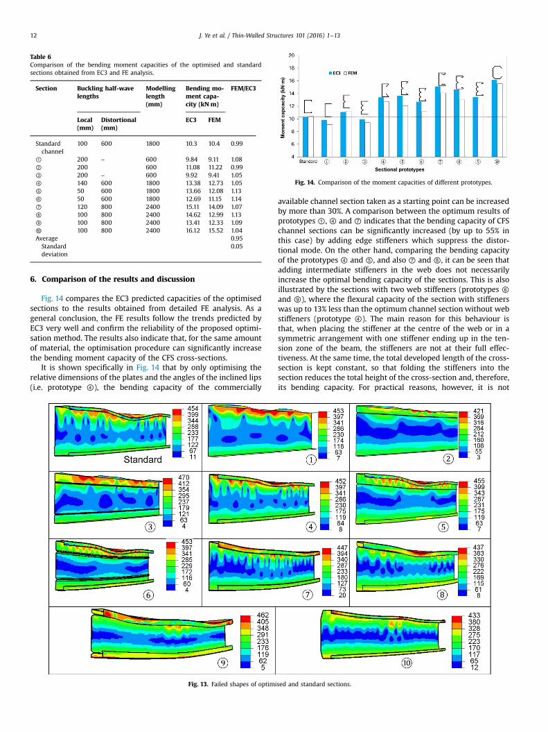
failed shapes at the ultimate load, obtained from FE analysis, are
also illustrated in Fig. 13.
Table 5
Effective cross-sections and buckled shapes of the folded-flange beams (presented at a consistent scale).
0
5
10
15
20
25
0 0 5 1 1 5
Mom
ent (k
Nm
)
M2001
M2002
M2003
M2501
M2502
M2503
Fig. 11. Moment-rotation curve of the folded-flange sections.
Fig. 12. Schematic view of the behaviour of axially compressed panels (adapted
from [38]).
J. Ye et al. / Thin-Walled Structures 101 (2016) 1–13 11
6. Comparison of the results and discussion
Fig. 14 compares the EC3 predicted capacities of the optimised
sections to the results obtained from detailed FE analysis. As a
general conclusion, the FE results follow the trends predicted by
EC3 very well and confirm the reliability of the proposed optimi-
sation method. The results also indicate that, for the same amount
of material, the optimisation procedure can significantly increase
the bending moment capacity of the CFS cross-sections.
It is shown specifically in Fig. 14 that by only optimising the
relative dimensions of the plates and the angles of the inclined lips
(i.e. prototype ④), the bending capacity of the commercially
available channel section taken as a starting point can be increased
by more than 30%. A comparison between the optimum results of
prototypes ①, ④ and ⑦ indicates that the bending capacity of CFS
channel sections can be significantly increased (by up to 55% in
this case) by adding edge stiffeners which suppress the distor-
tional mode. On the other hand, comparing the bending capacity
of the prototypes ④ and ⑤, and also ⑦ and ⑧, it can be seen that
adding intermediate stiffeners in the web does not necessarily
increase the optimal bending capacity of the sections. This is also
illustrated by the sections with two web stiffeners (prototypes ⑥
and ⑨), where the flexural capacity of the section with stiffeners
was up to 13% less than the optimum channel section without web
stiffeners (prototype ④). The main reason for this behaviour is
that, when placing the stiffener at the centre of the web or in a
symmetric arrangement with one stiffener ending up in the ten-
sion zone of the beam, the stiffeners are not at their full effec-
tiveness. At the same time, the total developed length of the cross-
section is kept constant, so that folding the stiffeners into the
section reduces the total height of the cross-section and, therefore,
its bending capacity. For practical reasons, however, it is not
Table 6
Comparison of the bending moment capacities of the optimised and standard
sections obtained from EC3 and FE analysis.
Section Buckling half-wave
lengths
Modelling
length
(mm)
Bending mo-
ment capa-
city (kN m)
FEM/EC3
Local
(mm)
Distortional
(mm)
EC3 FEM
Standard
channel
100 600 1800 10.3 10.4 0.99
① 200 – 600 9.84 9.11 1.08
② 200 600 11.08 11.22 0.99
③ 200 – 600 9.92 9.41 1.05
④ 140 600 1800 13.38 12.73 1.05
⑤ 50 600 1800 13.66 12.08 1.13
⑥ 50 600 1800 12.69 11.15 1.14
⑦ 120 800 2400 15.11 14.09 1.07
⑧ 100 800 2400 14.62 12.99 1.13
⑨ 100 800 2400 13.41 12.33 1.09
⑩ 100 800 2400 16.12 15.52 1.04
Average
Standard
deviation
0.95
0.05
Fig. 13. Failed shapes of optimised and standard sections.
Fig. 14. Comparison of the moment capacities of different prototypes.
J. Ye et al. / Thin-Walled Structures 101 (2016) 1–1312
recommended to place the stiffeners in an asymmetric config-
uration since errors during the installation of the beams would
almost be inevitable. Fig. 14 also highlights the increased efficiency
of the proposed folded-flange prototype compared to any other
prototype considered. It is shown that, for the same amount of
material, prototype ⑩ leads to a maximum flexural capacity which
is around 57% higher than the standard commercially available
channel section and 22% higher than the optimum lipped channel
section (prototype ④). Folded-flange sections are also easy to
manufacture and connect to typical floor systems and, hence, are
ideal candidates for practical CFS beam sections.
7. Summary and conclusions
In this paper, a practical framework is proposed to optimise CFS
beam cross-sections while considering code-based design con-
straints as well as manufacturing issues and practical limitations.
Using the framework, a commercially available CFS lipped channel
section was optimised based on ten different prototypes, including
a folded-flange cross-section, while keeping the material use
constant. A slight modification of the EC3 design methodology was
first developed in order to account for the multiple distortional
buckling modes which may occur in the folded-flange cross-sec-
tion. The particle swarm optimisation algorithm was then used to
obtain the solutions with the maximum flexural strength. The
accuracy of the modified design model and the effectiveness of the
proposed optimisation framework were also evaluated using de-
tailed non-linear FE analysis. The following conclusions can be
drawn:
� The FE simulations of the folded-flange sections confirm that
the proposed additions to the effective width based design
method in EC3 to account for the multiple distortional buckling
modes in the folded-flange section lead to accurate predictions
of the ultimate bending capacity.� By applying the proposed optimisation framework to laterally
braced beams, the bending capacity of a commercially available
CFS beam was increased by 30% by only optimising the relative
dimensions of the flat plates and the inclination of the lips. The
results also indicate that flanges with double fold lips have the
potential to considerably increase the flexural capacity of CFS
beams (by up to 50%), while using intermediate stiffeners in the
web does not necessarily increase the capacity of the sections.
As expected, plain CFS channel cross-sections provided the
minimum flexural capacity, even when adding intermediate
web stiffeners.� Folded-flange sections, which can be easily designed and
manufactured due to their simple sequence of straight plate
segments with a relatively small number of folds, are shown to
be viable and even superior alternatives to typical lipped
channel sections. For the same amount of material (i.e. the same
total coil width and plate thickness), the folded-flange section
possesses a flexural capacity which is 57% and 22% higher than
the selected commercial section and the optimum lipped
channel section, respectively.
Acknowledgement
This work was supported by the Engineering and Physical
Sciences Research Council (EPSRC) grant EP/L019116/1. The au-
thors would like to thank the EPSRC for their financial support.
References
[1] L. Fiorino, O. Iuorio, R. Landolfo, Designing CFS structures: the new school bfsin naples, Thin Wall Struct. 78 (2014) 37–47.
[2] J.B.P. Lim, D.A. Nethercot, Finite element idealization of a cold-formed steelportal frame, J. Struct. Eng. – ASCE 130 (2004) 78–94.
[3] J.B.P. Lim, D.A. Nethercot, Ultimate strength of bolted moment-connectionsbetween cold-formed steel members, Thin Wall Struct. 41 (2003) 1019–1039.
[4] J. Lee, S.M. Kim, H.S. Park, Y.H. Woo, Optimum design of cold-formed steelchannel beams using micro genetic algorithm, Eng. Struct. 27 (2005) 17–24.
[5] Y.S. Tian, T.J. Lu, Minimum weight of cold-formed steel sections under com-pression, Thin Wall Struct. 42 (2004) 515–532.
[6] J.H. Lee, S.M. Kim, H.S. Park, Optimum design of cold-formed steel columns byusing micro genetic algorithms, Thin Wall Struct. 44 (2006) 952–960.
[7] H. Adeli, A. Karim, Neural network model for optimization of cold-formedsteel beams, J. Struct. Eng.-ASCE 123 (1997) 1535–1543.
[8] K. Magnucki, M. Maćkiewicz, J. Lewiński, Optimal design of a mono-symme-trical open cross section of a cold-formed beam with cosinusoidally corru-gated flanges, Thin Wall Struct. 44 (2006) 554–562.
[9] K. Magnucki, M. Rodak, J. Lewiński, Optimization of mono- and anti-symme-trical I-sections of cold-formed thin-walled beams, Thin Wall Struct. 44 (2006)832–836.
[10] E. Magnucka-Blandzi, Effective shaping of cold-formed thin-walled channelbeams with double-box flanges in pure bending, Thin Wall Struct. 49 (2011)121–128.
[11] W. Ma, J. Becque, I. Hajirasouliha, J. Ye, Cross-sectional optimization of cold-formed steel channels to Eurocode 3, Eng. Struct. 101 (2015) 641–651.
[12] J. Ye, I. Hajirasouliha, J. Becque, A. Eslami, Optimum Design of Cold-formedSteel Beams Using Particle Swarm Optimisation Method, J. Constr. Steel Res.,2015, (in preparation).
[13] CEN, Eurocode 3: Design of Steel Structures, Part 1.3: General Rules—Supple-mentary Rules for Cold-formed Steel Members and Sheeting, in, Brussels:European Comittee for Standardization, 2005.
[14] AISI, North American Specification for the Design of Cold-formed SteelStructural Members, 2007 Edition, in: AISI S100-07, Washington, DC, 2007.
[15] J.Z. Leng, J.K. Guest, B.W. Schafer, Shape optimization of cold-formed steelcolumns, Thin Wall Struct. 49 (2011) 1492–1503.
[16] B.P. Gilbert, T.J.M. Savoyat, L.H. Teh, Self-shape optimisation application: op-timisation of cold-formed steel columns, Thin Wall Struct. 60 (2012) 173–184.
[17] H. Liu, T. Igusa, B.W. Schafer, Knowledge-based global optimization of cold-formed steel columns, Thin Wall Struct. 42 (2004) 785–801.
[18] J.Z. Leng, Z.J. Li, J.K. Guest, B.W. Schafer, Shape optimization of cold-formedsteel columns with fabrication and geometric end-use constraints, Thin WallStruct. 85 (2014) 271–290.
[19] A.B. Sabbagh, M. Petkovski, K. Pilakoutas, R. Mirghaderi, Development of cold-formed steel elements for earthquake resistant moment frame buildings, ThinWall Struct. 53 (2012) 99–108.
[20] CEN, Eurocode 3: Design of Steel Structures. Part 1-1: General Rules and Rulesfor Buildings, in, Brussels: European Comittee for Standardization, 2005.
[21] CEN, Eurocode 3: Design of Steel Structures, part 1-5: Plated Structural Ele-ments, in, Brussels: European Comittee for Standardization, 2005.
[22] AS/NZS, Cold-formed Steel Structures, in, Sydney: AS/NZS 4600, Joint Tech-nical Committee BD-082, 1996.
[23] Swarm Intelligence for Multi-objective Problems in Data Mining, Stud ComputIntell, 242, 2009, 1-287.
[24] R. Hassan, B. Cohanim, O. De Weck, G. Venter, A comparison of particle swarmoptimization and the genetic algorithm, in: Proceedings of the 1st AIAAMultidisciplinary Design Optimization Specialist Conference, 2005, pp. 18–21.
[25] S. Jeong, S. Hasegawa, K. Shimoyama, S. Obayashi, Development and in-vestigation of efficient GA/PSO-hybrid algorithm applicable to real-worlddesign optimization, IEEE Comput. Intell. Mag. 4 (2009) 36–44.
[26] R.E. Perez, K. Behdinan, Particle swarm approach for structural design opti-mization, Comput. Struct. 85 (2007) 1579–1588.
[27] Y. Shi, R. Eberhart, A modified particle swarm optimizer, in: EvolutionaryComputation Proceedings, 1998. IEEE World Congress on Computational In-telligence., The 1998 IEEE International Conference on, IEEE, 1998, pp. 69–73.
[28] Mathworks, Matlab R2011a, in, Mathworks, Inc, 2011.[29] ABAQUS, in, Hibbitt, Karlsson & Sorensen, Inc, Pawtucket, USA, 2007.[30] M.R. Haidarali, D.A. Nethercot, Finite element modelling of cold-formed steel
beams under local buckling or combined local/distortional buckling, Thin WallStruct. 49 (2011) 1554–1562.
[31] L. Gardner, M. Ashraf, Structural design for non-linear metallic materials, Eng.Struct. 28 (2006) 926–934.
[32] B. Schafer, CUFSM Version 3.12, in, Department of Civil Engineering, JohnsHopkins University, 2006. ⟨http://www.ce.jhu.edu/bschafer/cufsm/⟩.
[33] B.W. Schafer, T. Pekoz, Computational modeling of cold-formed steel: char-acterizing geometric imperfections and residual stresses, J. Constr. Steel Res.47 (1998) 193–210.
[34] Y. Shifferaw, B.W. Schafer, Inelastic Bending Capacity of Cold-Formed SteelMembers, J. Struct. Eng.-ASCE 138 (2012) 468–480.
[35] C. Yu, B.W. Schafer, Local buckling tests on cold-formed steel beams, J. Struct.Eng. – ASCE 129 (2003) 1596–1606.
[36] C. Yu, B.W. Schafer, Distortional buckling tests on cold-formed steel beams, J.Struct. Eng. – ASCE 132 (2006) 515–528.
[37] T.V. Galambos, Guide to Stability Design Criteria for Metal Structures, JohnWiley & Sons, USA, 1998.
[38] R.M. Jones, Buckling of Bars, Plates, and Shells, Bull Ridge Corporation, USA,2006.
J. Ye et al. / Thin-Walled Structures 101 (2016) 1–13 13