Development of Mine Transportation in Clifton- Morenci ...library.aimehq.org/library/books/AIME...
28
No. 1310-M. Issu~n WITH MINING AND METALLURGY. MARCH, 1924. DISCUSSION OF THIS PAPER IS INVITED. It should refera ably be presented in prson at the New York Meeting. February, 1924, when anabstract of the paper will be repd If thls 1s imqos- sible, discussion in writing may be sent to the Edltor, American Institute of Mlnlng and Metallurg~cal Engineers, 29 West 39th Street, New York. N. Y., for presentation by the Secretary or other representa- tive of its author. Unles~ special arrangement is made, the discussion of this paper wlll close Aprll 1, 1924. Any discussion offered thereafter should preferably be in the form of a new paper. Development of Mine Transportation in Clifton- Morenci District (New York Meeting, February, 1924) This paper describes the evolution of transportation at an important mining property, beginning at a time when the railhead was 400 mi, distant, ,and tracing the steps leading to the development of what is probably the heaviest ore train ever operated in underground mine service over narrow-gage tracks, a 300-ton ore train on a 20-in. track, at working costs closely approximati.ng those obtained on systems involving much greater capital expenditure. Useful where geological and Jinancial considerations render inadvisable the excavation and maintenance of large tunnels and heavier rolling stock. THE problem of transportation in the Clifton-Morenci district of Arizona has been one of peculiar difficulty and consequently has been an important factor in the cost of mining and treating the ores produced. From the. crude beginning made ovef 50 years ago, many changes have been necessary to keep pace with the increased output of copper. A heavy-duty haulage system has developed on the original 20-in. track gage to meet the existent metal-mine conditions. The transportation difficulties of this district may' be readily appre- ciated from the relief map shown in Fig. 1. The northern half of the district is high mountainous country and there is a general but irregular &op toward the southern part, where the country, although still rugged, is in reality a great sloping plain. This is cut by numerous ravines from'which the waters, in the rainy season, discharge into the channel of the San Francisco River. A chasm, 1000 ft. deep, has been eroded through the center of the district by Chase Creek, which is flanked by high irregular mountain masses, notably Copper Mountain, American Mountain, Coronado Mountain, and Markeen Mountain. The latter rises 2300 ft. above the bed of the creek. The San Francisco River has also cut a deep channel, though it is somewhat broader than Chase Creek. Eagle Creek traverses the extreme * Formerly General Manager, Arizona Copper Co., Ltd. t Superintendent, Phelps Dodge Morenci Branch. Copyright, 1924, by the American Institute of Mining and Metallurgical Engineers, Inc.
Transcript of Development of Mine Transportation in Clifton- Morenci ...library.aimehq.org/library/books/AIME...

No. 1310-M. I s su~n WITH MINING A N D METALLURGY. MARCH, 1924.
DISCUSSION O F THIS PAPER IS INVITED. It should refera ably be presented in p r son at the New York Meeting. February, 1924, when anabstract of the paper will be repd If thls 1s imqos- sible, discussion in writing may be sent to the Edltor, American Institute of Mlnlng and Metallurg~cal Engineers, 29 West 39th Street, New York. N. Y., for presentation by the Secretary or other representa- tive of its author. Unles~ special arrangement is made, the discussion of this paper wlll close Aprll 1, 1924. Any discussion offered thereafter should preferably be in the form of a new paper.
Development of Mine Transportation in Clifton- Morenci District
(New York Meeting, February, 1924)
This paper describes the evolution of transportation at an important mining property, beginning at a time when the railhead was 400 mi , distant, ,and tracing the steps leading to the development of what is probably the heaviest ore train ever operated in underground mine service over narrow-gage tracks, a 300-ton ore train on a 20-in. track, at working costs closely approximati.ng those obtained on systems involving much greater capital expenditure. Useful where geological and Jinancial considerations render inadvisable the excavation and maintenance of large tunnels and heavier rolling stock.
THE problem of transportation in the Clifton-Morenci district of Arizona has been one of peculiar difficulty and consequently has been an important factor in the cost of mining and treating the ores produced. From the. crude beginning made ovef 50 years ago, many changes have been necessary to keep pace with the increased output of copper.
A heavy-duty haulage system has developed on the original 20-in. track gage to meet the existent metal-mine conditions.
The transportation difficulties of this district may' be readily appre- ciated from the relief map shown in Fig. 1. The northern half of the district is high mountainous country and there is a general but irregular &op toward the southern part, where the country, although still rugged, is in reality a great sloping plain. This is cut by numerous ravines from'which the waters, in the rainy season, discharge into the channel of the San Francisco River. A chasm, 1000 ft. deep, has been eroded through the center of the district by Chase Creek, which is flanked by high irregular mountain masses, notably Copper Mountain, American Mountain, Coronado Mountain, and Markeen Mountain. The latter rises 2300 ft. above the bed of the creek.
The San Francisco River has also cut a deep channel, though it is somewhat broader than Chase Creek. Eagle Creek traverses the extreme
* Formerly General Manager, Arizona Copper Co., Ltd. t Superintendent, Phelps Dodge Morenci Branch.
Copyright, 1924, by the American Institute of Mining and Metallurgical Engineers, Inc.

2 M I N E TRAKSPORTATION I N CLIFTON-MORENCI DISTRICT
southwest portion of the area, where it has carved picturesquely through vast volcanic flows.
Faulting has left its mark upon the topography of the district by adding to the irregularities caused by erosion. Strong faults occur a t the Coro- nado mine and near the Longfellow incline a t Morenci. The canyon up which the Morenci Southern Ry. reaches Morenci follows a particu-
larly persistent fault. This fault is closely associated with the principal occurrences of the Morenci ores.
The ruggedness of the district made the problem of early railroad construction particularly difficult.
The geology of the ~orenci- lifto on district has been described a t length by the U. S. Geological Survey.' Attention will be called here
1 W. Lindgren: "Copper Deposits of the Clifton-Morenci District, Arizona," Prof. Paper 43 (1905).
NORMAN CAFMICHAEL AND JOHN KIDDIE 3
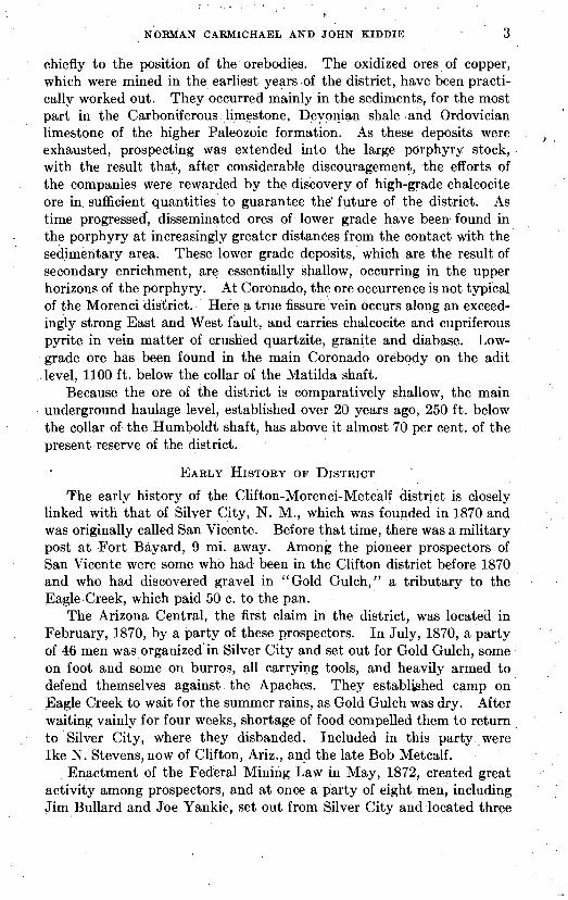
chiefly to the position of the orebodies. The oxidized ores of copper, which were mined in the earliest years of the district, have been practi- cally worked out. They occurred mainly in the sediments, for the most part in the Carboniferous limestone. Devonian shale and Ordovician limestone of the higher Paleozoic formation. As these deposits were , exhausted, prospecting was extended into the large porphyry stock, with the result that, after considerable discouragement, the efforts of the companies were rewarded by the discovery of high-grade chalcocite ore in sufficient quantities to guarantee the' future of the district. As time progressed', disseminated ores of lower grade have been. found in the porphyry at increasingly greater distances from the contact with the sedimentary area. These lower grade deposits, which are the result of secondary enrichment, are essentially sballow, occurring in the upper horizons of the porphyry. At Coronado, the ore occurrence is not typical of the Morenci district. Here a true fissure vein occurs along an exceed- ingly strong East and West fault, and carries chalcocite and cupriferous pyrite in vein matter of crushed quartzite, granite and diabase. Low- grade ore has been found in the main Coronado orebody on the adit level, 1100 ft. below the collar of the Matilda shaft.
Because the ore of the district is comparatively shallow, the main underground haulage level, established over 20 years ago, 250 ft. below the collar of the Humboldt shaft, has above it almost 70 per cent. of the present reserve of the district.
EARLY HISTORY OF DISTRICT
The early history of the Clifton-Morenci-Metcalf district is closely linked with that of Silver City, N. M., which was founded in 1870 and was originally called San Vicente. Before that time, there was a military post a t Fort Bayard, 9 mi. away. Among the pioneer prospectors of San Vicente were some who had been in the Clifton district before 1870 and who had discovered gravel in "Gold Gulch," a tributary to the Eagle Creek, which paid 50 c. to the pan.
The Arizona Central, the first claim in the district, was located in February, 1870, by a party oE these prospectors. In July, 1870, a party of 46 men was organized in Silver City and set out for Gold Gulch, some on foot and some on burros, all carrying tools, and heavily armed to defend themselves against the Apaches. They established camp on Eagle Creek to wait for the summer rains, as Gold Gulch was dry. After waiting vainly for four weeks, shortage of food compelled them to return to Silver City, where they disbanded. Included in this party ,were Ike N. Stevens, now of Clifton, Ariz., and the late Bob Metcalf.
Enactment of the Federal Mining Law in May, 1872, created great activity among prospectors, and at once a party of eight men, including Jim Bullard and Joe Yankie, set out from Silver City and located three

4 MINE TRANSPORTATION I N CLIFTON-MORENCI DISTRICT
additional claims in this district on the site of the present town of Morenci. These claims were the Montezuma, Copper Mountain and Yankie. While this location work was in progress, a second party started out from Silver City, in which were Captain Joy, sent by Mr.
, Ward of Detroit, Mich., and I. N. Stevens, to do the necessary work on the four claims, for patent. At almost the same time, a third party left, headed by Bob Metcalf and "staked" by the Lesinskys, merchants of Las Cruces, N. M. This party located ground in the vicinity of the site of Metcalf ,and then located the Longfellow mine a t Morenci.
A meeting was next called of all the men in the district, and the Copper Mountain Mining District was formed in August, 1872, with Joseph Yankie as the first District Recorder. This was then a part of Yavapai County, and the original locations were recorded a t Prescott, the county seat.
The Lesinskys put up the capital to build the first "adobe" furnace, which was erected on Chase Creek, below the foot of the present Long- fellow incline, in 1873. The concern was known first as the Francisco Mining Co.; later as the Longfellow Mining Co. Charcoal was used as fuel, and the ore was packed down steep trails on burros, from the Long- fellow mine, about 900 f t . higher than the furnace. This location proved unsatisfactory, so, later in 1873, a second adobe furnace was erected a t the junction of Chase Creek and the San Francisco River, where the town of Clifton now lies. A wagon road was built to the mines a t Morenci and water was hauled up and ore was hauled down. A ditch, up the Sap Francisco River, supplied water power to operate a fan for the blast for the furnace. Supplies were hauled in, and copper was taken out by ox-teams, via Silver City, from Independence, Kans., and later from La Junta, Colo. and Las Vegas, N. M., these places being terminals of the Atchison Topeka & Santa Fe Ry., as it was built westward.
In 1874, a disagreement occurred between the Lesinskys and Bob Metcalf. After some trouble, Metcalf acquired possession of Metcalf Hill, and the Lesinskys of the Longfellow mines. The Lesinskysoperated for many years with indifferent success, for added to their financial difficulties were the depredations of marauding bands of Apache Indians.
FIRST RAILROAD IN ARIZONA
During this time the ore from the Longfellow mine was hauled by wagon to the Smelter at Clifton, a t a cost of $10 per ton. The Lesinskys, recognizing the magnitude of the deposits, determined to construct the first .railroad built in Arizona, in order to reduce the cost of hauling the ore. This road was built during 1878 and the early part of 1879, along the bed of Chase Creek from Cllfton to a point below the Longfellow mine. At the same time, a gravity incline, in two separate sections, was built from the mine down to Chase Creek, 900ft. below; the oie was carried down

NORMAN CARMICHAEL AND JOHN KIDDIE 5 .
the incline in cars and the cars were sent over the new railroad, without unloading. The railroad was 455 mi. long, with grades ranging from 2.5 to 5 per cent.
The engineer of construction was Capt. Nicholas S. Davis, who was also engineer a t the mines, and he was assisted by Mr. Unthank. Captain
- -
FIG. ~.-I?IRsT INDUSTRIAL LOCOhIOTNE I N ARIZONA. (PHOTOGRAPH FURNISHED BY H. K. PORTER CO.)
FIG. 3.-PORTION OF ROADBED OF FIRST RAILWAY I N ARIZONA (WHERE MAN IS STAND- ING) BELOW THE PRESENT CORONADO RAILROAD.
Davis belonged to the California Column during the Civil War, and before the war had worked in mines in California, and it was this experience that led him to adopt a track gage of 20 in., with which he was familiar.

6 MINE TRANSPORTATION IN CLIFTON;MORENCI DISTRICT
There were no tracks underground in any of the mines, all the ore being removed by wheelbarrows, but later on the underground track was laid on 20-in. gage to conform to that already existing on the surface railroad and inclines. Mules were the first motive power, but they were not satisfactory and a locomotive, Fig. 2, for this work was ordered from the H. K. Porter Co. ;the records of that company show that this locomotive was shipped in April of 1880, by steamer around the Horn from New York City to San Francisco. From San Francisco, the only route open for freight at that time was by rail to Fort Yuma and thence to Clifton by ox-team, the route unquestionably followed by this locomotive, which arrived at its destination in the fall of the same year. '
The engine had cylinders 6 in. in diameter by 10 in. long; saddle tank; 20-in. gage; and four 22-in. chilled-tread driving wheels. It used wood for fuel. The shipping weight was four tons, _and in working order it weighed 13.000 lb.
An interesting item in the Porter company's records is the memoran- dum that this locomotive was to "have an injector, " a new departure a t that time. It was also provided with a crosshead pump. I t was built to haul 10 empty cars weighing 2800 lb. each, on a 4.5 per cent. maximum grade with 90-ft. radius curves and 16-lb. rails. It was lettered the "Coranada" by the manufacturers, but it was re-lettered in later years and called the "Little Emma."
As soon as the railroad was completed from Clifton as far as Long- fellow, the work of extending it up Chase Creek to.the Metcalf mines was undertaken. A portion of this original roadbed, below the present Coronado railroad, is shown in Fig. 3.
DETROIT COPPER MINING CO.
In January, 1875, William Church, assisted by his brother John, acquired the four original claims of the district from the Ward Estate, and organized the Detroit Copper Mining Co. In 1880, this company built a small smelter on the Frisco River about 3 mi. below Clifton. All the ore was hauled down from the mines to the smelter by wagon. Two years later the smelter was removed to Morenci. In 1887, the Phelps Dodge Co. bought the property from Mr. Church. Until 1901, all incoming supplies and outgoing copper were shipped via the Long- fellow incline, over the baby gage to and from Clifton. In that year, the Morenci Southern, a narrow-gage railroad, was completed from Guthrie, on the Arizona & New Mexico R. R., to Morenci, a distance of 18 mi. This road was laid with 50-lb. steel. There was a maximum grade of 3.5 per cent. on tangents and a maximum curvature of 40". The unique feature of this construction was a series of five complete loops, one by the use of a tunnel near the San Francisco River and four by the use of high wooden trestles in a narrow canyon below Morenci.

The total cost of this road was approximately $28,000 per mile, including equipment.
ARIZONA COPPER COMPANY, LTD.
In the late fall of 1880, the Southern Pacific Ry., being constructed from the west, reached Lordsburg, N. M.
In 1882, the Arizona Copper Co. Ltd., of Edinburgh, Scotland, pur- chased the mines of the Lesinskys and Bob Metcalf. To provide
. adequate transportation facilities for the district, so that serious develop- ment could be undertaken, the company built a 3-ft. gage railroad from Lordsburg to Clifton, a distance of 70 mi. This road, built in 1883 and 1884, mas originally named the Clifton and Southern Pacific, but later was changed to the Arizona & New Mexico. I t was laid with 48-lb. and 50-lb. steel. This railway was later extended up to the Longfellow incline, replacing that portion of the original baby-gage line,
. the extension being completed in August, 1901. Bins at the foot of the Longfellow incline were used for about one year, to transfer the Metcalf ore brought down to this point on the 20-in. road. After this time, the change to 36 in. was completed to Metcalf.
The next step forward was taken in 1900 and 1901, when the Arizona & New Mexico was widened to standard gage, the light steel being replaced with 60-lb. and 75-lb. As the light steel was taken up from the Clifton & Metcalf railway (now called the Coronado R. R.) and the main line of the A. & N.M., it was used on the main haulage roads around the mines, which is the reason that the electric haulage system to be described later is entirely laid with 48- and 50-lb. steel rails.
SHANNON COPPER CO.
The Shannon Copper Co. was organized in November, 1899, with mines a t Metcalf, Ariz. Previous to 1910, ore and supplies were hauled between Metcalf and Clifton by the Coronado R. R. of the Arizona Cop- per Co. Ltd. During 1909 and 1910, in order to handle its own ores, the Shannon company constructed the Shannon Arizona Ry., 10 mi. long, a t a total cost, including equipment, of approximately $60,000 per mile. The road was laid with 75-lb. steel.
As the mines of both companies became greatly extended and began to work lower grade ores requiring concentration, it became necessary to handle larger quantities of ore and supplies. Mules were largely replaced by steam locomotives and many miles of surface tracks were laid in the district, especially a t Morenci and Coronado. Grades of from 4 per cent. to as muchas 7.5 per cent. were in vogue. To meet these condi- tions, the size and weight of the steam locomotives were steadily increased.

8 MINE TRANSPORTATION IN CLIFTON-MORENCI DISTRICT
Since the arrival of the first tiny locomotive described, sixteen of these 20-in. gage engines have been purchased for this district, all manufactured by the H. K. Porter Co. The last two, supplied to the Detroit Copper Co., show what remarkable performance can be secured on so small a gage. The specifications of these locomotives are: Piston diameter, 11 in.; stroke, 16 in.; driving wheel, 30 in.; .wheel base, 5 ft. 3 in.; length overall, 18 ft. 6 in.; height overall, 10 f t . 9 in,; weight as originallysupplied, 37,000 lb.; present weight, with cast-iron bumpers added back and front,
. 40,000 lb.; tractive force, 7540 lb. These locomotives as originally
FIG. 4.-A ~ O - T O X L O C O M O T J V E O N A 20-IN. GAGE.
supplied were coal burning but they were later converted to oil burners. These engines have large "overhang," see Fig. 4, but in spite of that fact derailments are rare.
All the earlier cars were of the "rocker" type, the body resting upon half circles of angle iron by which they could be dumped to either side. When underground mining began to exceed in impmtance the surface mining, the type of car was changed to that of the inverted V-bot- tom variety with dumping doors along both sides. These were of 3f4- ton capacity a t first, but later were increased to 435, 5f5 and finally to 10 tons.
On main haulage levels, mules were generally used underground, and in some cases still are. In 1905, the Arizona Copper Co. replaced mules

NORMAN. CARMICHAEL AND JOHN KIDDIE 9
by electric locomotives on the surface and important levels of the Hum- bolt mine. The heavy grades on the surface roads of the company's property at Morenci were eliminated in 1906. The locomotives were
furnished by the Jeffrey Manufacturing Co., the first type being a single 6-ton unit, cast-iron frame with 220-volt motors. The driving wheels were of chilled cast iron; each 6-ton unit was equipped with two 15-hp. series motors and had a rated drawbar pull of 1500 lb. at 8 mi. per hour;

10 MINE TRANSPORTATION I N CLIBTON-MORENCI DISTRICT
the brakes were hand operated. These motors, though now rather small, are still giving excellent satisfaction on surface after 16 years of continuous service.
During the period from 1905 to 1913, the haulage of ore from the ~Gmbold t mine, now the largest producer, to the concentrator at Morenci was performed entirely by electric motors and cars of 3$5, 444 and 534 tons'capacity. Previous to 1913, the Coronado mine was quite isolated and the output was handled as follows: A shaft 700-ft. deep, the Matilda, connected the various working levels; through which the ore was hoisted in 1-ton cars to surface and dumped into bins. From these bins it was transferred to a baby-gage steam railway a mile long and delivered to the top of the Coronado incline, which was 3300 f t . long with 1100 ft. differ- ence in elevation between head and foot. Over this incline it was lowered and dumped into bins; another 20-in. gage steam train conveyed the ore to bins on the Coronado R.R. and from there it was hauled to Clifton, a distance of 7 mi., and delivered to a concentrator.
Plans had been laid for changing all this and for connecting the Coronddo mine with the Humboldt transportation system through an extension of the electric haulage. These plans called for (a) driving a 3000-ft. tunnel from the Clay mine to daylight (in driving this 8- by 9-ft. heading, a speed of 799 f t . in 31 consecutive days was attained2); ( b ) driving an adit tunnel 5000 f t . from surface into the Coronado mine; (c) connecting these two pieces of work by an outside track, skirting along the hill for 6600 ft.; and (d) sinking the Coronado shaft 400 f t . deeper to connect with this new level. Fig. 5 shows a section along the electric haulage road, which illustrates this piece of work.
In solving this problem, the question of gage was again carefully considered: i. e.,fwhether to continue the use of the present 20-in. system or to adopt the 36-in. gage. It was finally decided to develop the present 20-in. system so as to procure as nearly as possible the same costs as with the 36-in. track and heavier equipment, for the following reasons:
1. The entire haulage system of the Humboldt mine was already 20- in., of which the extension would form but a part. The adoption of a different gage requiring either a three-rail system underground or the changing of the existing elaborate system including tunnels, tracks, chutes, and all accessories, involved an enormous installation cost.
2. The difficulty of supporting ground in the case of such large openings as a 3-ft.-gage track would necessitate.
Fig. 5 shows where the ore is mined and hoisted, also the location of the principal orebodies under present consideration. Mining operations are carried on above the Humboldt second level and above its extension into the Coronado mountain, called the 1100-ft. level. The Coronado
Eng. & Min. Jnl. (Aug. 17, 1912).

NORMAN CARMICHAEL AND JOHN KIDDIE 11
ore is transferred by electric haulage in 3%-ton cars on the 700-ft. level to ore chutes which deliver it to the 10-ton haulage system. Similarly,
, a part of the Humboldt ore mined above the adit level is transferred on the adit level in 554-ton cars with electric motors and dumped to the main haulageway 250 f t . below. On the second level of the Humboldt, the ore is loaded from chutes, weighed on platform scales and dumped into two sets of pockets at the No. 6 hoisting shaft. The combined capacity of these pockets is 2300 tons. It is hoisted in 5-ton skips from a point in the shaft 80 ft. below the haulage level into a 1000-ton mill bin. The capacity of the concentrator is 4000 tons per day.
L o c o ~ o ~ r v ~ s FOR 300-TON TRAIN
The problem of building the most powerful locomotive for the 20411. gage was then submitted to the makers, but their only suggestion was to change the tires from chilled iron to steel to increase the tractive effort or to couple two locomotives of two units each with two controls, requir- ing two operators and making a tractor 50 ft. long. This was not satis- factory, and finally our own electrician devised a mea.ns of coupling three units. The three coupled units had a single control composed of two controllers placed one above the other and operated from the same lever which gave a tractor with an approximate drawbar pull of 10,000 lb. The wiring was brought out symmetrically to a terminal block and connected with jumpers so that the third unit could be quickly uncoupled.
An oversize compressor was installed for the 10-ton haulage train, requiring a larger air receiver and a triple air valve. On the third, or replaceable, unit the original controller and pantagraph was left to operate in case of emergency. Locomotives supplied by the Jeffrey Manu- facturing Co. for this heavy service ,were equipped with driving motors increased in size from 15 to 30 hp., which is the largest motor that can be placed between the driving wheels. Steel-tired wheels were substituted for chilled-cast ones. The entire locomotive equipment, totaling 23 single units, has been furnished by the Jeffrey h!tanufacturing Co.
The general specifications and dimensions of these triple-head loco- motives were as follows :
Weight . . . . . . . . . . . . . . . . . . . . . . . . . . . . . . . . . . . . . . . . . 18tons Volts . . . . . . . . . . . . . . . . . . . . . . . . . . . . . . . . . . . . . . . . . . . 250 Number of motors.. . . . . . . . . . . . . . . . . . . . . . . . . . . . . . 6 Control. . . . . . . . . . .* . . . . . . . . . . . . . . . . . . . . . . . . . . . . . Center Wheels . . . . . . . . . . . . . . . . . . . . . . . . . . . . . . . . . . . . . . . . . . Inside Rated drawbar pull.. . . . . . . . . . . . . . . . . . . . . . . . . . . . . 9000 lb. Starting drawbar pull.. . . . . . . . . . . . . . . . . . . . . . . . . . . . 10,000 Ib. Miles per hour at full load speed.. . . . . . . . . . . . . . . . . . 6
. . . . . . . . . . . . . . . . . . . . . . . . . . . . . . . . . . . . . . Trackgage 20in. Overall width. . . . . . . . . . . . . . . . . . . . . . . . . . . . . . . . . . . . . 40.5 in.

12 MINE TRANSPORTATION IN CLIFTON-MORENCI DISTRICT
. . . . . . . . . . . . . . . . . . . . Length of frame for each uni t . . 11 ft. 3 in. Height ot frame.a,bove rail. . . . . . . . . . . . . . . . . . . . . . . . 37 in. Heightovercover . . . . . . . . . . . . . . . . . . . . . . . . . . . . . . . . 48in. Maximum overall height above rail with trolley pole
lockeddown . . . . . . . . . . . . . . . . . . . . . . . . . . . . . . . . . . . 55in. Wheel base. . . . . . . . . . . . . . . . . . . . . . . . . . . . 42 in.
. . . . . . Diameter steel-tired wheels. . . . . . . . . . 36 in. Frame . . . . . . . . . . . . . . . . . . . . . . . . . . . . structural steel
. . . . . . . . . . . . . . . . . . . . . . . . . . . . . . . . . . . . . . Trolley diamondtype
The next step was to provide the largest car that could be operated on track of this gage. A 10-ton car supplied by the manufacturers could
FIG. 6.-ONE-TON, 5%-TON AND 10-TON CARS ON 20-IN. GAGE.
not be operated except on a perfectly straight track. The entire truck and draft rig was redesigned and rebuilt in our own shops, air brakes were added to one-half of the cars, and the other half were equipped with train pipes. To show the relative size of this car, the following com- parisons are given (see also Fig. 6) :
3%-TON W~-TON 10-TON . . . . . . . . . . . . . . . . Capacity.. '. . . . . . . . . . . 65 cu. ft. 110 cu. ft. 200 cu. ft.
Wheels C. I. diam.. . . . . . . . . . . . . . . 24" 24" 24" Length inside. . . . . . . . . . . . . . . . . . . . . 8' 0" 8' 0" 11' 6" Width.. . . . . . . . . . . . . . . . . . . . . . . . . 4' 6" 5' 6" 5' 10" Overall length. . . . . . . . . . . . . . . . . 11' 4" 11' 4l' 14' 6" Height above rail. . . . . . . . . . . . 4' 945"' 5' 3" 5' 8%'' Coupler height. . . . . . . . . . . . . . . . . . 25" 25" 17" Wheel base.. . . . . . . . . . . . . . . . . . . . . . . 4' 0" 4' 0" 5' 0" Underframe channels.. .. . . . . . . . . . . . . 7" 7" 8" Thickness of body plates.. . . . . . . . . . 4i" 4i" 36'' Journals. . . . . . . . . . . . . . . . . . . . . . . . . . . . . . . 334"X5%" 3Qi" X746" 4X1 'X7%" Weight-empty.. . . . . . . . . . . . . . . . . . . . . . . . . 5500 lb. 7000 lb. 9700 lb.

NORMAN CARMICHAEL AND JOHN KIDDIE 13
Cars are all steel construction and are of one general type; namely, gable bottomed, side dumping. I n all cases the journal bearings are of M. C. B. type, outside the wheels, with suitable double-coil springs over the journal boxings. All cars have full length doors, each of which is swung by three or four hinges and held by a like number of catches or dogs on a through horizontal square rod. This in turn is operated by a hand lever a t one end of the car, fastened by a slip link. All cars are provided with standard-design double-coil spring draft gear. Couplers on the 334- and 5%-ton cars are of malleable cast iron, to take links and pins; on the 10-ton cars, M. C. B. standard automatic couplers of three- quarter size are used. The difference of 8 in. in the coupler heights between the 10-ton and the smaller cars, as given in the table, calls for special connecting bar. For the same reason, the locomotives are provided either with a special double-mouthed drawhead or with two single drawheads, one placed immediately above the other.
The 10-ton cars, as originally supplied, were equipped with Hyatt spiral roller bearings between the wheels. Rollers were 6 in. long and were used with a 3-in. diameter axle. Wheels were ribbed single-plate type, one tight and one loose. No springs were provided, the axle housings being bolted rigidly to the body channels. This general design proved unsatisfactory, and was changed a t once to provide bearings outside of the wheels, as already noted.
The single-plate wheels were not strong enough to stand up under the load, and the double-plate type was substituted. The latter wheel has proved entirely satisfactory. To take the wearof thefollower platesin the draft gear of the 10-ton cars and to prevent the consequent failure of the 8-in. body channels, >/4-in. replaceable wearing plates of scrap material are now used. Hand brakes of regulation type are used on all surface cars, but underground no hand brakes are used. The air-brake equip- ment for one 10-ton car, as supplied by the Westinghouse Air Brake Co., consists of:
1' Type D, 6- by %in. brake cylinder 1 Type D, auxiliary reservoir 1 H. I. triple valve 1 Release valve complete 1 Cut-out cock 2 Self-locking angle cocks, 1 by 1G in. 2 1%- by %-in. hose with F. P. 4 co~~plings.
All trolley wire over surface track is 00, figure eight, copper. On surface, this wire is maintained a t a height of 9 ft. and supported by standard flexible brackets and cross-span construction, as developed for similar traction systems. Underground, Section ,35 of the Arizona State Mining Code provides that "electric trolley wires in all mines now (1912)

14 MINE TRANSPORTATION IN CLIFTON-MORENCI DISTRICT
equipped with same shall be a t least 6)4 ft. above the floor. In all mines hereafter so equipped, a t least 7 f t . above the floor." Tunnel sections for both timbered and untimbered motor tunnels have been standardized since the passage of the above law and are shown in Figs. 7 and 8. The height of the trolley in these sections is 7 ft. 5 in. and 7 ft. 10 in. respectively.
At first, the practice was to use rigid barn hangers, but it was found that occasional high peaks of ore bent the trolley wire upward on both sides of the hanger, and the resulting kinks seriously interfered with the operation of the collectors, besides causing bad burning from the excessive sparking a t those points. To meet these difficulties, fleible supports
FIG. 7.-~ROSSSECTION OF TIMBERED FIG. 8.-CROSS-SECTION OF UNTIMBERED TUNNEL. TUNNEL.
have been adopted. Several different types of these supports have been installed and tried out on the various underground roads, and two have been selected as best fitting our requirements. One is the straight-line suspension made by the General Electric Co., Form'H, consisting of a '
straight-line hanger and trolley ear carried by a %s-in. guy wire, see Fig. 7. This support is used on straight trolley lines, where it gives excellent satisfaction. On curves, however, the center piece will shift and cause trouble, therefore a second, more expensive type is used for curves. This is a straight-line suspension with composition strain insu-
. lators carried in the same manner as the first one described, see Fig. 9 In ground where timbers are moving, the trolley wire difficulty is
taken care of by frequently dead-ending both ways with the ends over- lapping for a distance of about 5 feet.
All electric locomotives are provided with diamond,or pantagraph type of collectors. A slide has been tried instead of the roller, but was discarded after a short trial because of increased trouble from panta-

NORMAN CARMICHAEL AND JOHN KIDDIE - . 15
now is shown in Fig. 10. This pantagraph is much more rigid than the f is t type used, and the roller rarely slips off the trolley wire. The first type consisted of four members or legs in a single plane; with this con- struction, the wooden sticks are the weakest members, and if the panta-

graph catches on a trolley wire, these sticks are broken; they are designed to be easily and quickly replaced.
Type D trolley frogs, made by the Ohio Brass Co., are now used. These are 23 in. long overall, 20°, with short cam tips. Homemade brass frogs, first used, have not proved satisfactory. To prevent stick breakage in the pantagraph due to frequent catching and "hanging up" of the roller, guards have been found necessary between the.branching -
Composite Plan
FIG. 10.-PLAN AND ELEVATIONS OF PANTAGRAPH COLLECTOR.
trolley wires. These guards are about 4 f t . long, made of three iron pipes, 35 in. in diameter, bolted to two iron bars, above, which in turn aise held by clips owthe two trolley wires. Instead of >$in. pipe,'00 figure eight trolley wire has been tried for the guards, but has proved too flexible to stand up under hard usage.
TRACKS AND BONDING
All main haulage roads are laid with'50-lb. steel rails, bonded yith 4/0 compressed terminal bonds of flexible wire. Secondary haulage-

NORMAN CARMICHAEL AND JOHN KIDDIE 17
ways are laid with 35- or 25-lb. steel, bonded with 210 bonds of similar type. Temporary tracks are laid with 25-lb. steel and bonded either with channel pins and 210 solid annealed copper wire, or with removable flexible bonds with tapered steel pins. To facilitate inspection, all bonds are exposed, the holes for the terminals being placed outside of the splice plates, 29 in. apart, with the bond itself measuring 32 in. in length. These types of bonds are used because they can be installed by unskilled labor. In addition to the regular rail bonding, all tracks are croisbonded between the two rails. The haulage-track systems on the adit and second level are tied together, through the Humboldt shaft, by two 500,000-cm. cables, and a second tie is to be installed through the Liverpool shaft. From these Humboldt shaft cables and the adit level track system, four return conductors of 410 bare copper wire go to the negative bus on the d.c. switchboard. All rails on the adit level, for several hundred feet in both directions from the point of taking off this return, are double bonded. At the Coronado adit, the return current is conducted in a similar manner, to the Coronado sub-station panel.
Underground haulage tracks are laid with 6- by 8-in. ties, 4 ft. long, spaced 30-in. centers. - On surface, the ties are also 6 by 8 in., spaced 30 in., but are 5 ft. in length. Spikes 5 in. long are used throughout.
Grades in the old parts of the mine, though somewhat variable, as a rule are not over 0.5 per cent. The maximum for the old portion of the second level haulageway is 0.9 per cent., which occurs just north of the Humboldt shaft for a distance of only 450 ft. In all tunnels driven since the adoption of the electric haulage, a grade of 0.4 per cent. in favor of the load has been maintained. Experience has shown that slightly less grade would more nearly equalize the drawbar pull for the loaded and empty trains. Curves of 100-ft. radius have been installed in all recent work, where it is possible to do so. For the 10-ton car haulage, the minimum curve has an 80-ft. radius, and for the 5;d-ton car haulage, a 40-ft. radius.
For the 50-lb. rails, stiff bolted frogs are used with cast-iron spacing blocks. These frogs are constructed of standard steel, except on the second level haulageway, where a number of frogs with manganese steel inserts have been installed. The insert is a one-piece casting designed to give a full tread bearing over the area of maximum wear. The cost of these frogs was from two and a half to three times greater than that of the regular frog, but present indications are that they will be cheaper in the end. Frogs for the lighter rails are partly of the above type and partly those riveted on steel plates.
Split switches are used very generally on the 50-lb. tracks, both surface and underground, but stub switches are used around loading chutes and other points which are very difficult to keep clean. Stub switches are also used for the lighter rails.

18 ' MINE TRANSPORTATION IN CLIFTON-MORENCI DISTRICT
The form of switch stand commonly used is an inexpensive one of the ground-throw type, provided with either plain or weighted lever, which operates at right angles to the track. The weights are provided with a handle to facilitate the throwing. In recent years, stands with the throw parallel to the track have been tried out and are considered more satisfactory, as there is less liability to accident in operating them.
All underground track switches are provided with signal lights, which I show the position of the switch. Green lights indicate that the main I
trunk line is clear; red, that the switch is set for some branch or siding
7 Ground Gmneh'on R Red Lens
Si nu1 Mie islnsfolled Parw//e/ To S accd31ir. &izinh/& fmm, mdon fevel k;tfTrnl/qy ond~s fne bed dfmm Tmlly Mie Thmqqh ~onf~ru~';R~onhdor~henlo~mohw ,s ~n fhe BIO&
off the main line. This is accomplished by means of a double-throw electric switch controlled by the track-switch operating mechanism, actuat- ing the negative side of the wires from the colored lamps which are con- nected to the trolley circuit.
A block signal system has been devised and installed underground and on the dangerous curves on the surface lines. This installation con- sists of a separate signal wire of No. 2 hard drawn copper, paralleling and 3 in. away from the trolley wire. When the locomotive is in the block, the 20-in. copper roller on the pantagraph bridges these two wires, impressing trolley voltage on the signal wire and thereby lighting 25- watt, mill-type lamps in semaphore lanterns a t both ends of the block and on the curves. These lamps are all placed on the same side of the tunnel and on the same side as the switch lights. The lamps are con- nected to ground. Red and yellow lenses are used on the lanterns, which have two globes in parallel, thus insuring a signal even though one globe burns out. The accompanying diagrammatic sketch, Fig. 11, shows the operation on a straight track, on a curve, and in a side drift. The lamps on curves can be seen from either direction. They are installed

for the benefit of men working in the tunnel, to notify them of an approach- ing train. I n the side drift, a lamp shows the condition of the block on the straight track, and a lamp on the straight track near the entrance of the side drift shows the condition of the block in the side drift. Under- ground, the small secondary wire is independently supported by the same type of flexible hanger as is used for the trolley wire: on surface, it is supported from the trolley wire by a common clip on each of the two wires, the clips being fastened together with a composition ball insulator.
Side Elevat ion Front Elevation FIG. 12.-LOADING CHUTE FOR 10-TON CARS.
,
The block-signal system, as described, does not give absolute protec- tion, as it does not provide'for detached cars or trucks left standing or moving within the block, but during eight years of operation, there has been no serious trouble due t o these causes. This block system has the advantage of a very low cost of installation and a low upkeep charge. It can be attended to by a helper and does not need the service of an expert electrician.
An illustration of the standard loading chutes for the 10-ton cars is given in Fig. 12. This chute is designed to load one 10-ton car a t a single

vJ 20 MINE TRANSPORTATION I N CLIFTON-MORENCI DISTRICT
spotting. The two regular brakemen attached to the train operate the chute doors from the top of the platform.
SOTJRCE OF POWER
Power for all of the various operations is generated a t the power plant situated a t the smelter in South Clifton. The installation consists of three 2000-kw. Curtiss type, 1800-r.p.m. steam turbines, direct con- nected to 2500-k~.-a., 6600-volt, three-phase, 60-cycle, General Electric generators, each of which is direct connected t,o three 417-kv.-a. 6600- t o 13,200-volt star connected auto transformers. Steam at 170-lb. gage and 75" superheat is supplied by five Sterling boilers of 713 hp. fired by waste heat from two 22- by 100-ft. reverberatory furnaces, also three 713-hp. and three 384hp. Sterling boilers, oil fired. Under normal operating conditions, an average of 4000 kw. electric power is required for smelting, concentrating, mining and miscellaneous company opertitions. Of this total, the average consumption for electxic haulage a t the mines, both surface and underground, is from 2 to 2.5 per cent., and the peak load for the haulage is about 5 per cent. of the powerhouse peak.
Power is transmitted from central power plant to sub-stations a t 13,200 volts, three-phase, over two circuits of No. 2/0 R. & S.-gage stsnd- ard copper cable carried on "Tripartite" steel poles with pin insulators, to No. 6 mill sub-station, n distance of 5 mi., and then over two circuits of No. 4 B. & &gage stranded copper cable in "Tripartite" steel poles to Coronado sub-station, a distance of 23/4 miles.
Sub-stations
There are three sub-stations, located respectively at No. 6 concen- trator, a t the Humboldt adit and a t the Coronado adit. All power for No. 6 mill is passed through the No. 6 sub-station, which, in addition, delivers all current for IJongfellow division mining purposes a t 2300 volts, '
three-phase, to the Humboldt adit sub-station, over a single 250,000-cm. circuit. At this station are situated two large synchronous motor-driven air compressors and two 300-kw. rotary convertors, -one used a t a time, which supply all direct current for haulage and other purposes. Similarly, a t the Coronado adit sub-stations there are two smaller compressors, one driven by a synchronous motor and one by an induction motor, and two 150-kw. rotary converters furnishing direct current for underground and surface haulage in the Coronado mining division. A 2300-volt surface line from this station to the Matilda shaft hoist supplies a 150-kw. rotary converter, which in turn supplies power t o operate the Matilda hoist, and for the Coronado mine. .

NORMAN CARMICHAEL A N D JOHN KIDDIE 21
Distribution of Power from Sub-station
For reasons of economy and convenience of operating, the surface and underground roads are sectionalized or divided into separate units, depending on their location or on their duties, which may change on any of the three different shifts. In this way the current is cut off from any section in which the particular work of that section has been finished for the day. There are six of these sections a t the Longfellow division and two a t the, Coronado. Each section is served by separate 250-volt feeder circuits direct from the sub-station. These lines are of 500,000- cm. triple-braid weatherproof cable, and each is provided with an 800- amp. circuit breaker and a 450-amp. watt-hour meter at the sub-station. In addition to the needs of the haulage system, there are numerous direct- current motors, lights, etc., in each section.
The current to each section is generally tapped into the trolley lines at a point nearest the sub-station. In the case of some of the smaller sections, no additional feeding is needed, but in the larger ones the main feeder is extended to parallel the trolley line along the main haulage artery and the potential is kept up by tapping over to the trolley wire at intervals of from 350 to 750 ft., as best suits the particular loads and duties within the section. For example, the second level haulage of the Humboldt mine is connected up as follows: Two 500,000-cm. weatherproof cables are taken from the Humboldt adit down the Humboldt shaft to the second level. At the foot of the shaft they are connected through three switches into the three sections comprising this level. One main feeder of 500,000-cm. cable, from this point, parallels the main Humboldt, Clay and Coronado haulageway, from which taps are taken off the trolley wire a t average intervals of 500 feet.
A second example is that of the Coronado adit. This unit is served by a 750,000-cm. circuit from the Coronado sub-station tapped to the trolley wire a t the portal. From this point a 500,000-cm. feeder 6500 ft. long parallels the trolley line to the bottomof the Matildashaft. Asecond feeder of 500,000 cm. from the Matilda shaft hoist house is strung down the shaft. As this shaft is very wet with strong copper water, the cable used has varnished cambric insulation, lead covered, steel wire armor and jute cover, all kept well painted. This feeder is 1300 ft. long and is tapped on the 700-ft. level for the transfer electric haulage and 50-hp. motor-driven ventilating fan, and is connected through a 600-amp. carbon break circuit breaker to the 1100-ft. adit level feeder.
The surface roads at Coronado are paralleled by two 6500-ft. 4/0 bare feeders to the Queen adit, which is the junction point between the Coro- nado and Longfellow systems. At this point the two haulage systems are tied together through a 300-amp. automatic reclosing circuit breaker, arranged to open aGtomatically in case of trouble on either end, and to
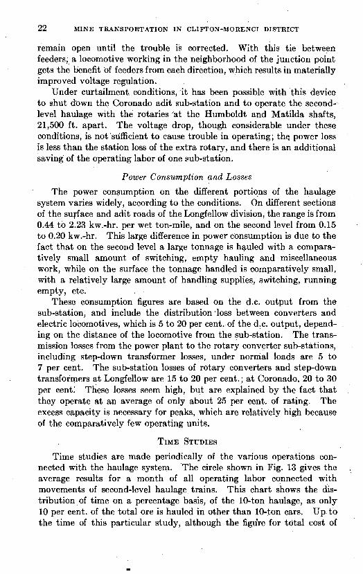
22 M I N E TRANSPORTATION I N CLIFTON-MORENCI DISTRICT
remain open until the trouble is corrected. With this tie between feeders, a locomotive working in the neighborhood of the junction point gets the benefit of feeders from each direction, which results in materially improved voltage regulation.
Under curtailment conditions, it has been possible with this device to shut down the Coronado adit sub-station and to operate the second- level haulage with the rotaries 'at the Humholdt and Matilda shafts, 21,500 ft. apart. The voltage drop, though considerable under these conditions, is not'sufficient to cause trouble in operating; the power loss is less than the station loss of the extra rotary, and there is an additional saving of the operating labor of one sub-station.
Power Consumption and Losses
The power consumption on the different portions of the haulage system varies widely, according to the conditions. On different sections of the surface and adit roads of the Longfellow division, the range is from 0.44 to 2.23 kw.-hr. per wet ton-mile, and on the second level from 0.15 to 0.20 kw.-hr. This large difference in power consumption is due to the fact that on the second level a large tonnage is hauled with a compara- tively small amount of switching, empty hauling and miscellaneous work, while on the surface the tonnage handled is comparatively small, with a relatively large amount of handling supplies, switching, running empty, etc.
These consumption figures are based on the d.c. output from the sub-station, and include the distrihution.loss between converters and electric locomotives, which is 5 to 20 per cent. of the d.c. output, depend- ing on the distance of the locomotive from the sub-station. The trans- mission losses from the power plant to the rotary converter sub-stations, including step-down transformer losses, under normal loads are 5 t o 7 per cent. The sub-station losses of rotary converters and step-down transformers a t Longfellow are 15 to 20 per cent.; a t Coronado, 20 to 30 per cent: These losses seem high, but are explained by the fact that they operate a t an average of only about 25 per cent. of rating. The excess capacity is necessary for peaks, which are relatively high because of the comparatively few operating units.
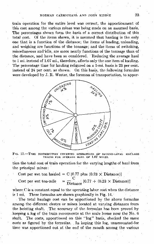
Time studies are made periodically of the various operations con- nected with the haulage system. The circle shown in Fig. 13 gives the average results for a month of all operating labor connected with movements of second-level haulage trains. This chart shows the dis- tribution of time on a percentage basis, of the 10-ton haulage, as only 10 per cent. of the total ore is hauled in other than 10-ton cars. Up. t o the time of this particular study, although the figGre for total cost of
I
NORMAN CARMICHAEL AND JOHN K I D D ~ E 23 %
train operation for the entire level was correct, the apportionment of this cost among the various mines was being made on an assumed basis. The percentages shown form the basis of a correct distribution of this total cost. Of the items shown, it is assumed that hauling is the only one that is a function of the distance; the items of loading, unloading, and weighing are functions of the tonnage; and the items of switching, miscellaneous and'idle, are more nearly functions of the tonnage than of the distance, and have been so considered. Reducing the average haul to 1 mi. instead of 1.07 mi., therefore, affects only the one item of hauling. The percentage time for hauling refigured on a 1-mi. basis is 23 per cent. instead of 24 per cent. as shown. On this basis, the following formulas were developed by J. R. Wester, the foreman of transportation, to appor-
F I G . TIME DISTRIBUTION COVERING OPERATIONS OF SECOND-LEVEL HAULAGE TRAINS FOR AVERAGE HAUL OF 1.07 MILES.
tion the total cost of train operation for the varying lengths of haul from the principal mines :
Cost per wet ton hauled = C [0.77 plus (0.23 X Distance)] C
Cost per wet ton-mile = - Distance
[0.77 + (0.23 X Distance)]
where C is a constant equal to the opcrating labor cost when the distance is 1 mi. These formulas are shown graphically in Fig. 14.
- The total haulage cost can be apportioned by the above formulas among. the different chutes or mines located a t varying distances from the hoisting shaft. The accuracy of the formulas has been proved by keeping a log of the train movements a t thc scale house near the No. G shaft. The costs, apportioned on this "log" basis, checked the same costs as figured by the formulas. In keping this log, unaccounted-for time was apportioned out a t the end of the month among the various

24 MINE TRANSPORTATION IN CLIFTON-MORENCI DISTRICT
mines on the basis of total hours actually charged to that mine. The cost of train operation includes the labor of the train crew only. As this crew, comprising three men, loads, hauls and dumps the ore, this figure
. represents the cost of these three operations.
COST O F TRANSPORTING WITH 300-TON TRAIN
The costs for the year 1921, prior to suspension af operations, are given below for the transportation of second-class ores from the various mines to the pockets a t No. 6 shaft. The costs include loading and dumping, and ail expense incidental to haulage, except repairs to the
FIG. COST CURVES OF .TRAIN OPERATION, SECOND-LEVEL ELECTRIC HAULAGE.
tunnels and loading chutes, which are considered as items of general mine expense rather than of transportation.
Average daily tonnage (dry). . . . . . . . . . . . . . . . . . . . . . . . . . . . . . . . . . . Average haul in miles..
Cost per Wet-ton Mile Operating train.. . . . . . . . . . . . . . . . . . . . . . . . ;
. . . . . . . . . . . . General-including supervision. . . . . . . . Cleaning tracks and blasting chutes :.
Track maintenance.. . . . . . . . . . . . . . . . . . . . . . Trolley line maintenance.. . . . . . . . . . . . . . . . . Locomotive maintenance. . . . . . . . . . . . . . . . . Car maintenance.. . . . . . . . . . . . . . . . . . . . . . . . Block signal maintenance. . . . . . . . . . . . . . . . . Power . . . . . . . . . . . . . . . . . . . . . . . . . . . . . . . . . . New equipment.. . . . . . . . . . . . . . . . . . . . . . . . . . .
0.0515 0.0466 0.0341
* These are the items which are referred to in Figs. 13 and 14.

NORMAN CARMICHAEL AND JOHN KIDDIE 25
The average power consumption for the entire second level, corre- sponding to these cost figures, was 0.20 kw.-hr. per wet ton-mile, measured a t the outgoing meter a t the sub-stations. The wages in effect during the period recorded were:
Motormen. . . . . . . . . . . . . . . . . . . . . . . . . . . . . $5.04 per shift Brakemen.. . . . . . . . . . . . . . . . . . . . . . . . . . . . 3.80 per shift
The regular haulage train consists of thirty 10-ton cars with a "triple- . head" Jeffrey locomotive, see Fig. 15. I t is operated by a crew of three
men; one motorman and two brakemen. This crew loads the train a t
FIG. 15.-A 300-TON TRAIN O N 20-IN. GAGE, SHOWING TRIPLE-HEAD LOCOMOTIVE.
the mine chutes; hauls and dumps the ore a t the hoisting pockets. All ore is weighed on a Fairbanks-Morse track scale on the main haulage road, near the hoisting shaft. This scale has a platform 42 f t . long with a capacity of three cars. Tbe weighing is done by a man who also samples the ore in the cars, the cost of which is not charged to the haulage. One miner is used, on the day shift only, for blasting "hung-up" chutes, and a spare brakeman is carried, on the day shift, who does the track clean- ing. A blacksmith and helper, on the day shift, make all the necessary car repairs, including those to air-brake equipment, and do the train oiling. One electrician and a helper are employed on the day shift, who do all locomotive repair work and oiling, all track bonding, block and switch signal repairing and upkeep of trolley lines. Track work is done by one head trackman with from one to three laborers. One transportation foreman is employed on the day shift.
A locomotive is never operated continuously for more than 8 hr. The running speed of the train varies from 5 to 7;4 mi. per hour. About

26 MINE TRANSPORTATION IN CLIFTON-MORENCI DISTRICT
1800 tons per shift are hauled from the Humboldt mine with one train. Time studies give the following averages for the ~ u m b o l d t mine:
TIME. MINUTFS
To load thirty 10-ton cars at mine chutes.. . . . . . . . . . . . . . . . . . . . . . 35 To weigh thirty 10-ton cars at scales . . . . . . . . . . . . . . . . . . . . . . . . . . . . 7 To dump thirty 10-ton cars at pockets.. . . . . . . . . . . . . . . . . . . . . . . . 19
On a 0.4 per cent. down grade, the 30-car train, running at a speed of 7 mi. per hour, is stopped by the air brakes in from 20 to 22 seconds, in a distance of from 125 to 145 ft. The voltage drop is not excessive when starting the heavy loaded trains from rest. The average drop is only 22 volts, with a maximum of 32 bolts. The average time taken by motormen to cut out all resistance, motors in full parallel, is 40 sec. and the total time -of acceleration is 1 min. 45 sec. Arc masters were
. tried out on the control, but their use has been discontinued.
\
From the installation of the electric haulage in 1906 to the present time, there have been four fatal accidents attributed to contact with either the trolley wire or a feeder wire.
1. In 1908, a brakeman was killed a t No. 26 chute on the Humboldt adit. After helping to load a train of 5>6-ton cars, he jumped down from the overhead loading platform upon the rear of thd locomotive, instead of using the ladder provided for this purpose. In doing this, his neck came in contact with the trolley wire. His feet were wet and the shock . was-instantly fatal.
2. In 1912, two muckers were shoveling up spill along the haulage tracks near No. 28 chute, Humboldt adit, behind a standing 5%-ton car. One of these men started to climb over the car to the opposite end and it was thought that his neck came in contact with a bare feeder wire. He fell forward against the edge of the cas-ustained a blow over the heart. His death resulted.
3. In 1914, while the shift was coming off a t the Coronado mine, a mucker attempted to climb over the end of one of the cars of the train regularly used to haul the men out. The train was standing on a siding near the Matilda shaft and had not yet been switched into its regular place, where a switch cuts the current off the trolley line. His neck came in contact with the live wire and he was instantly killed.
4. In 1915, while driving the Coronado adit heading, a mule driver, whose duty it was to haul 556-ton cars of waste, was found dead. There were no witnesses, but the Coroner's jury decided that he must have stood up on. the drawhead and come in contact with the trolley wire. His feet were dry and no marks were found upon his body.

As more effective precautions have been taken and safety devices have been improved, the accident rate has been materially decreased. This is shown by the figures of comparative tonnages handled for the
. . above four fatalities, as follows :
The underground haulage tunnels are well lighted. All switch and block-signal lights are kept on one side of the tunnel, and on the opposite side is installed a series of white lights. Each white light indicates a place of safety, into which a workman can step to allow a train to pass. These places are spaced about 100 ft. apart. Where possible, existing branch drifts are used but where these are not available special safety. . * holes are constructed. The drifts in the neighborhood of the,safety places are whitewashed to afford all possible light. One white light in the back of the drift illuminates each frog and switch. This light is placed so that it cannot be seen from along the haulageway.
The haulage drifts are kept clean to prevent slipping or falling. The open ends of frogs are filled with plank, for the same reason. Electric trolley wires are Geing gradually brought up to standard height, and bare feeder wires underground have been entirely eliminated. The design of the loading chute has been improved, making it impossible to jump down upon the train from the overhead platform, and removing all reasonable possibility of accidental contact with the trolley wire.
At all points where men, timber, or supplies of any kind are loaded . or unloaded, provision is made for cutting off the current in the trolley wire by means of necessary section insulators and single blade switches. When repair work is in progress on the haulage drifts, the,trolley line is first " killed."
Electric bells and semaphore arms, operated by the block-signal system, are situated a t the mine tunnel portals and at both ends of surface tunnels, to give warning of approaching trains. Solenoid crossing bells with 10-in. gongs are used; the semaphores are made by our own electrical department.
ACKNOWLEDGMENT
In preparing this article, we wish to acknowledge the assistance rendered by the technical staff of both the Arizona Copper Co. Ltd. and the Phelps Dodge Corpn.; by Mr. Ike Stevens, of Clifton, Ariz.; by
. 28 MINE TRANSPORTATION' IN CLIFTON-MORENCI DISTRICT
, .
the H. K. Porter Co. of Pittsburgh, Fa.; and by Geo. H. Kelly, Arizona State Historian.
ADDENDUM
Since the preparation of this article, the properties of the Arizona Copper Co. Ltd. have been merged with those of the Phelps Dodge Corpn. The merger was completed in December, 1921, and at the same time the Arizona & New Mexico R. R. was transferred to the El Paso & Southwestern system: