Development of military aircraft from 1914 to 1918 V1 · similar to today’s hang-gliders. These...
14
1 Development of military aircraft from 1914 to 1918 Overview Aim To explore forces: gravity lift and drag with hands on activities Investigating flight Creating a model biplane. Curriculum links Key Stage 2 Science • pushes, pulls and opposing forces • gravity and air resistance as forces • measuring forces • working scientifically
Transcript of Development of military aircraft from 1914 to 1918 V1 · similar to today’s hang-gliders. These...

1
Development of military aircraft from 1914 to 1918
Overview Aim
To explore forces: gravity lift and drag with hands on activities
Investigating flight
Creating a model biplane.
Curriculum links
Key Stage 2 Science
• pushes, pulls and opposing forces
• gravity and air resistance as forces
• measuring forces
• working scientifically

2
Development of military aircraft from 1914 to 1918
Bastion in the Air
Exhibition at RAF Scampton The exhibition at RAF Scampton takes up much of the Dambuster Hangar. This tableau features three replica aeroplanes, staged to suggest the crews have just left the scene, with bits of aircraft on the ground for repair, weapons being serviced along with other items that might have belonged to the airmen.
There is a backboard, which includes a large LED screen showing relevant aviation footage.
The first exhibit is a deskinned Sopwith Camel, with people working on it as a form of interpretation.
There are two other replica aircraft a DH2 with a propeller at the back and a Rumpler C VII (German). The project has benefited from close collaboration with museums and heritage organisations in Germany, providing a unique insight into the development of aerial combat from both British and German perspectives.
When enemy aircraft crashed, behind Allied lines, the Allies would try to get the aircraft up and running again to see how it worked and learn from the technology.
In addition, there are storyboards explaining the stories behind the exhibit.
There is a Wall of Heroes telling stories of individuals from different backgrounds who came from Lincolnshire, or came to Lincolnshire to serve in the Royal Flying Corps or Royal Naval Air Service in the First World War. Images are up to 1.5 metres high.
Artificial barbed wire, evoking the trenches, creates a barrier between the public and the aircraft.
There are interpretation boards on Royal Flying Corps and RAF Brattlesby (Scampton).
There are displays of the graves of airmen who died in Lincolnshire during the First World War. Squadrons or families paid for the graves so they were ornate. This is another interesting facet of the story.

3
Flying forces: gravity, lift and drag There are essentially three forces acting on anything that flies.
• Gravity – due to the weight of the aircraft and pulls downwards.
• Lift – upward force generated by the aircraft’s wings, helicopter rotor blades or hot air/gas inside a balloon.
• Drag – air resistance (friction) due to the aircraft’s movement.
For an aircraft to fly, the downward pull of gravity must be overcome by a greater upward force of lift. In a fixed-wing aircraft, this upward lift is generated by the movement of air over the wings as the aircraft moves forward through the air.
In a helicopter, the spinning rotor blades generate this upward lift.
In a balloon, such as a Zeppelin, the lift is generated because the gas inside the balloon is less dense than the air surrounding the balloon.
Drag is the force of air resistance as the aircraft pushed its way through the air. It is effectively the friction caused as aircraft moves through the air. The amount of drag is related to the speed of the aircraft; higher speed gives a higher drag. That is why faster aircraft are more ‘streamlined’ so that drag is reduced as much as possible.
Flying forces – early attempts Early attempts at flight often tried to replicate the flapping of bird wings. They failed because humans are unable to generate sufficient upward force (lift) by flapping constructed wings. Even with lightweight, modern materials, this form of flight is still only achievable by birds, bats and insects.
More successful attempts used large kites and aircraft similar to today’s hang-gliders. These rely on lift caused by the prevailing winds and upward movements of air (thermals). Kites can rise from the ground if there is sufficient wind, whilst hang-gliders and glider aircraft need to be launched in some manner to gain their initial height.
Lighter-than-air flight (balloons) The first really successful and controllable flights used lighter-than-air balloons. In the 1780’s the Montgolfier brothers developed hot air balloons that could carry passengers.
In this instance, lift is generated because the air contained within the balloon is heated by a burner. The hot air inside the balloon is less dense than the cold air outside. The total weight of the balloon, hot air, basket and passengers it carries is less than the weight of the volume of air it displaces. This generates uplift and the balloon rises (‘hot air rises’).
Montgolfier hot air balloon, 1783. Image: Wikimedia

4
This principle is exactly the same as floating and sinking in water. If the object is less dense than water, the up thrust will cause it to float.
One problem with using hot air to generate lift is that a lot of fuel needs to be carried to maintain the heat in the balloon and keep it aloft for long periods of time. Also, as balloon sizes increase, even more fuel is required. To overcome this, large airships were developed that used gases that were lighter than air.
Zeppelins were developed in Germany around the 1900’s. They had rigid internal framework with an external skin that enclosed a number of separate hydrogen-filled balloons. Hydrogen gas is less dense than air and does not need to be constantly heated. These airships could stay in the air indefinitely and were the first forms of intercontinental air travel, for example passenger-carrying Zeppelins crossed the Atlantic. The height of the airship could be controlled by the addition or removal of air as ballast. Forward motion and steering was supplied by engines and propellers.
The biggest problem with these airships was that hydrogen gas can be flammable and explosive. A flaw that was vividly exposed in the Hindenburg disaster in 1937 when a passenger-carrying Zeppelin burst into flames when coming in to land in New jersey, USA. However, by the nature of their design, and the height at which they flew, Zeppelins were not easy to shoot down when they were used for bombing raids on the UK mainland during the First World War.
Airships remain in use today, mostly for promotional purposes but some are being developed as environmentally-friendly long-haul transport aircraft. Modern airships use helium gas instead of hydrogen. Helium is an inert gas and so is not flammable. Helium is also the gas used to fill party balloons that are readily available from card-shops and other suppliers.
Hindenburg, 1937. Image: Wikimedia
Modern Zeppelin, 2003. Image: Wikimedia
5
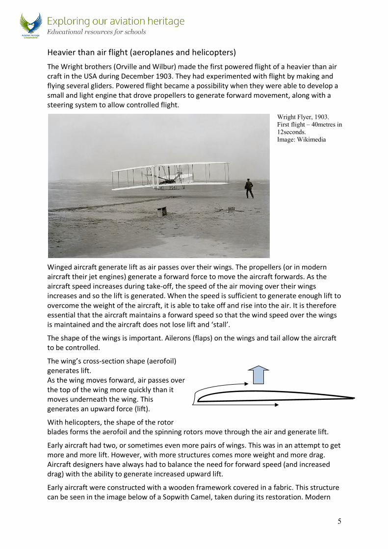
Heavier than air flight (aeroplanes and helicopters) The Wright brothers (Orville and Wilbur) made the first powered flight of a heavier than air craft in the USA during December 1903. They had experimented with flight by making and flying several gliders. Powered flight became a possibility when they were able to develop a small and light engine that drove propellers to generate forward movement, along with a steering system to allow controlled flight.
Winged aircraft generate lift as air passes over their wings. The propellers (or in modern aircraft their jet engines) generate a forward force to move the aircraft forwards. As the aircraft speed increases during take-off, the speed of the air moving over their wings increases and so the lift is generated. When the speed is sufficient to generate enough lift to overcome the weight of the aircraft, it is able to take off and rise into the air. It is therefore essential that the aircraft maintains a forward speed so that the wind speed over the wings is maintained and the aircraft does not lose lift and ‘stall’.
The shape of the wings is important. Ailerons (flaps) on the wings and tail allow the aircraft to be controlled.
The wing’s cross-section shape (aerofoil) generates lift. As the wing moves forward, air passes over the top of the wing more quickly than it moves underneath the wing. This generates an upward force (lift).
With helicopters, the shape of the rotor blades forms the aerofoil and the spinning rotors move through the air and generate lift.
Early aircraft had two, or sometimes even more pairs of wings. This was in an attempt to get more and more lift. However, with more structures comes more weight and more drag. Aircraft designers have always had to balance the need for forward speed (and increased drag) with the ability to generate increased upward lift.
Early aircraft were constructed with a wooden framework covered in a fabric. This structure can be seen in the image below of a Sopwith Camel, taken during its restoration. Modern
Wright Flyer, 1903. First flight – 40metres in 12seconds. Image: Wikimedia

6
materials today would include aluminium, lightweight metal alloys and carbon fibre composites.
Children can be challenged to think about the properties of materials used to make aeroplanes (light weight, strong, durable).
7
Development of military aircraft from 1914 to 1918
Classroom activities
Flying forces presentation
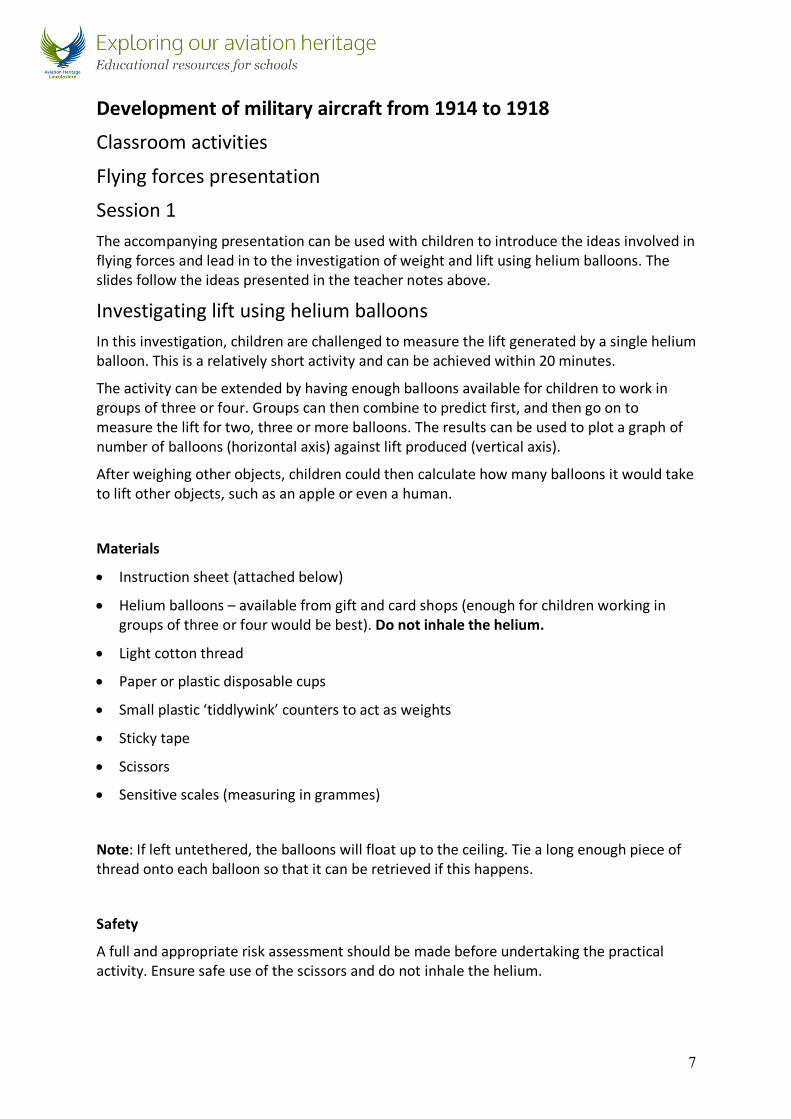
Session 1 The accompanying presentation can be used with children to introduce the ideas involved in flying forces and lead in to the investigation of weight and lift using helium balloons. The slides follow the ideas presented in the teacher notes above.
Investigating lift using helium balloons In this investigation, children are challenged to measure the lift generated by a single helium balloon. This is a relatively short activity and can be achieved within 20 minutes.
The activity can be extended by having enough balloons available for children to work in groups of three or four. Groups can then combine to predict first, and then go on to measure the lift for two, three or more balloons. The results can be used to plot a graph of number of balloons (horizontal axis) against lift produced (vertical axis).
After weighing other objects, children could then calculate how many balloons it would take to lift other objects, such as an apple or even a human.
Materials
• Instruction sheet (attached below)
• Helium balloons – available from gift and card shops (enough for children working in groups of three or four would be best). Do not inhale the helium.
• Light cotton thread
• Paper or plastic disposable cups
• Small plastic ‘tiddlywink’ counters to act as weights
• Sticky tape
• Scissors
• Sensitive scales (measuring in grammes)
Note: If left untethered, the balloons will float up to the ceiling. Tie a long enough piece of thread onto each balloon so that it can be retrieved if this happens.
Safety
A full and appropriate risk assessment should be made before undertaking the practical activity. Ensure safe use of the scissors and do not inhale the helium.

8
How much can a helium balloon lift?
You are going to see how much a helium-filled balloon can lift.
1. Measure three pieces of cotton thread. Cut them so they are each 20cm long.
2. Use a small piece of sticky tape to attach each thread at one end to the bottom of the balloon.
3. Hold onto the threads. Feel the balloon pulling up.
4. Get a small cup.
5. Use the scales to weigh the cup and make a note of its weight.
6. Use sticky tape to attach the strings from your balloon to the cup.
7. Check to see that it still pulls upwards. Do not let it float out of your reach.
8. Put plastic counters into the cup one at a time.
9. Put just enough counters into the cup so that the balloon floats level. Not moving up or moving down. Get as close to this as you can.
10. Remove the counters and weight them using the scales.
11. Calculate the total weight of the counters and the cup. This is the lift that is produced by the balloon.

9
Development of military aircraft from 1914 to 1918
Session 2 Investigating flight using paper gliders The easiest way to investigate flight is using paper gliders. Show children how to make a paper glider; an example design is shown below and in the presentation.
Explain that the gliders need a forward motion to fly. They cannot 'take off' on their own. This can be used to link the idea of wings generating lift when there is a forward motion.
The initial investigation can take 15 minutes but once children are able to make and test their gliders, they can be set a new design challenge to extend the activity as needed. Whilst making the paper aeroplanes is relatively simple, children can be challenged to modify the design to achieve specific outcomes such as:
• Flying the furthest distance
• Having the longest flight time
• Being the most accurate
• Flying in a straight line
• Flying in a curve.
Children can achieve these by modifying and testing their designs before a final ‘fly-off’ competition. Designs can be changed by modifications such as: by adding small folds to the wings, changing wing shape, trying different launch speeds and angles, adding small plasticine weights to modify the balance, changing the materials used and the size of the glider.

10
Making a paper glider
Use an A4 piece of paper and fold in sequence along the dotted lines.
Safety
Conduct a risk assessment before undertaking any of the practical activities below. For example, have children take care to launch gliders safely so that they do not cause any damage or hit other children in the face. Launching the gliders in an open space such as the hall will give more space.
Image from Wikimedia

11
Session 3 Investigating flight using a foam glider This design for a model glider uses a disposable foam plate as a source of material. It can be used to extend the investigation to also incorporate an element of design technology (design, make, build and test).
The types of challenges that can be set, and the safety considerations, are the same as in the previous investigation and so will not be repeated here. The flight of the glider is influenced by the size and position of the plasticine weight and children should be encouraged to see the effects of its movement.
Materials
• Thin foam disposable plate (23cm or 9inch diameter are suitable but bigger and smaller can be tested)
• Scissors
• Sticky tape
Making the glider
1. Make two cuts across the plate to form a wing that is 8cm deep.
2. Use the remaining foam to make a triangular tail piece of approximately 6cm x 4cm.
3. Use sticky tape to attach the tailpiece to the middle of the wing – leave about 4cm of the tail piece projecting over the back of the wing.
4. Add a piece of plasticine or BluTak to the front of the wing (approximately 2cm diameter x 0.5cm thick).
5. Gently launch the glider to see how it flies. Adjust the position of the plasticine weight to get it flying level rather than stalling up or down. This can be quite challenging.

12
Children can again modify their design to see the effect of things such as the speed of launch, angle of launch, position of the plasticine weight and addition of paper wing flaps Ailerons).

13
Development of military aircraft from 1914 to 1918
Session 4 Making a model biplane Early aircraft had designs with two layers of wings (biplane) or in some instance even more. Building on the foam glider, children can make a biplane and modify its weight distribution to see how well it flies.
Cut out another wing from a new foam plate. Connect it to the original glider, or make a new glider so that they can be compared side-by-side. Use cocktail sticks, secured with sticky tape, to connect the wings. This can be quite tricky and so give children time to make their biplane glider.
Safety: before their use, use scissors to cut off the sharp ends of the cocktail sticks.
Achieving a good balance is quite tricky and this activity gives children a very good opportunity to try, test, modify and develop their design. Additional flaps (ailerons) can be added to wings to help give stability and directional control.
As a final development, a drinking straw can be used to give the model a fuselage. Again, balancing and flying the glider will require a great deal of testing and refining of their design.

14
Flight with rubber band power In the previous investigations, the aircraft that have been made have been gliders and required launching. Powered flight can be investigated using commercially-available model aircraft. These have a propeller that is powered by a twisted elastic band. They still require launching but achieve forward thrust whilst the elastic band turns the propeller.
Models require assembly and so may be suitable for an after-school club or design-technology activity. They can be used to investigate factors such as any modifications of their design and also the number of twists given to the elastic band.
Suitable inexpensive models can be obtained from model shops or online retailers. The one shown below is a biplane and so can be used to model the early aircraft that children have studied earlier.
https://www.amazon.co.uk/TOOGOO-Rubber-Elastic-Powered-Airplane/dp/B071VR79WD/ref=sr_1_51?ie=UTF8&qid=1513853030&sr=8-51&keywords=planes+foam
Alternatively, an online search using ‘elastic band aeroplane’ will give other suppliers and designs. Some of the models are very sophisticated. There are many different examples, and a great deal of information on how to make model aeroplanes available on-line.