Generator Stator Rewinds: A Review of the Stator Rewind Process

Mitsubishi Heavy Industries Technical Review Vol. 52 No. 2 (June 2015) 47
*1 Power Electric Machine Design Department, Generator Division, Mitsubishi Hitachi Power Systems, Ltd. *2 Engineering Manager, Power Electric Machine Design Department, Generator Division, Mitsubishi Hitachi Power
Systems, Ltd.
Development of Large Capacity Turbine Generators for Thermal Power Plants
YASUNORI SATAKE*1 KAZUHIKO TAKAHASHI*2
TAKAMI WAKI*1 MITSURU ONODA*2
TAKAYASU TANAKA*1
With the background of electric power demand growth and effective resource utilization, demandfor larger-capacity turbine generators has been increasing. Mitsubishi Hitachi Power Systems, Ltd.(MHPS) has developed a 1300 MVA-class turbine generator with a direct water cooled stator system that has 1.2 times as much capacity as the preceding generator. The developed turbine generator adopts various technologies that increase capacity, and has left the factory after gaining favorable results in factory tests for the evaluation of the performance and reliability of the applied technologies. As a result of enhanced cooling performance through the development of a high heat transmission insulation system, the basic design of a large-capacity generator with indirect hydrogen cooling instead of the conventional direct stator water cooling has been completed, andit is estimated that the capacity of the designed generator can be increased to 900 MVA class for both 50 Hz an 60 Hz.
|1. Introduction In terms of global electric power demand growth and efficient resource utilization,
large-scale coal fired power generation and high-efficiency large gas turbine combined cycle power generation have been attracting attention as the base load power source alternative to nuclear powergeneration, and demand for such power generation is increasing. With this background, demand forlarger- capacity and higher-efficiency turbine generators has also been on the rise.
MHPS has been focusing on the development of large-capacity turbine generators, and has developed and produced a 1300 MVA-class generator for a thermal power plant, releasing it recently after gaining favorable results in factory tests. This paper describes the technologies that increase capacity applied to the developed generator, their verification, and the results of the factory test. In addition, MHPS is working on an increase of the capacity of a high-efficiencyindirect hydrogen cooling system that can make cooling water equipment unnecessary, and hascompleted the basic design of a 900 MVA-class generator to which technologies that increase capacity are applied. This paper also introduces the development status of the designed generator.
|2. Increase of capacity of turbine generator A turbine generator is an energy converter that converts the mechanical energy of a steam
turbine or a gas turbine into electrical energy. A generator includes coupled phenomena ofelectromagnetic, heat, ventilation, cooling, vibration, etc., and therefore is designed inconsideration of the interactions between them. The capacity of generators has been increased along with the development of indirect air cooling, indirect hydrogen cooling, and direct watercooling for cooling the stator coil in response to the increased heat generated inside.
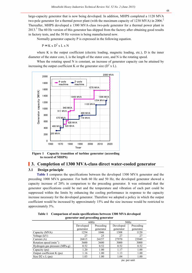
Figure 1 shows the capacity transition of turbine generator made by MHPS. The generatorcapacity shows an increasing trend year by year in response to market demand growth. MHPScompleted direct water-cooled large-capacity generators including a 1570 MVA four-pole generator for a nuclear power plant in 20041 and has finished the basic design of a 2000 MVA class
Mitsubishi Heavy Industries Technical Review Vol. 52 No. 2 (June 2015) 48
large-capacity generator that is now being developed. In addition, MHPS completed a 1120 MVAtwo-pole generator for a thermal power plant (with the maximum capacity of 1230 MVA) in 2006.2
Thereafter, MHPS developed a 1300 MVA-class two-pole generator for a thermal power plant in 2013.3 The 60 Hz version of this generator has shipped from the factory after obtaining good results in factory tests, and the 50 Hz version is being manufactured now.
Normally generator capacity P is expressed in the following equation.
∝P K x D2 x L x N
where K is the output coefficient (electric loading, magnetic loading, etc.), D is the innerdiameter of the stator core, L is the length of the stator core, and N is the rotating speed.
When the rotating speed N is constant, an increase of generator capacity can be attained by increasing the output coefficient K or the generator size (D2 x L).
Figure 1 Capacity transition of turbine generator (accordingto record of MHPS)
|3. Completion of 1300 MVA-class direct water-cooled generator 3.1 Design principle
Table 1 compares the specifications between the developed 1300 MVA generator and thepreceding 1000 MVA generator. For both 60 Hz and 50 Hz, the developed generator showed acapacity increase of 20% in comparison to the preceding generator. It was estimated that the generator specifications could be met and the temperature and vibration of each part could besuppressed within the limits by enhancing the cooling performance in response to the capacityincrease necessary for the developed generator. Therefore we adopted a policy in which the outputcoefficient would be increased by approximately 15% and the size increase would be restricted to approximately 3%.
Table 1 Comparison of main specifications between 1300 MVA developed
generator and preceding generator
60Hz 50Hz
Developed generator
Preceding generator
Developed generator
Preceding generator
Capacity (MVA) 1254 1046 1308 1120 Voltage (kV) 27 25 27 27 Current (A) 26815 24157 27970 23949 Rotation speed (min-1) 3600 3600 3000 3000 Hydrogen gas pressure (MPa-g) 0.52 0.52 0.52 0.52 Capacity (pu) 1.20 1.00 1.17 1.00 Output coefficient K (pu) 1.16 1.00 1.13 1.00 Size D2 x L (pu) 1.03 1.00 1.04 1.00 pu: per unit

Mitsubishi Heavy Industries Technical Review Vol. 52 No. 2 (June 2015) 49
For proceeding with the design, we implemented detailed design reviews repeatedly, and adopted design review based on failure mode (DRBFM) to extract failure modes related to changesfrom the preceding generator. We then performed pre-examination of their countermeasures and reflected the results in the design. 3.2 Applied technologies and verification
For an increase of generator capacity, various design technologies were applied to thedeveloped generator Figure 2). The specific examples are described below. The results of variousmeasurements and verifications in the factory test of the 60 Hz version of the developed generatorare also shown.
Figure 2 Technologies applied to 1300 MVA-class direct water cooled generator
(1) Enhancement of cooling performance If the temperature in the generator increases too much, insulation degradation of the coil
accelerates, resulting in insulation breakdown, or the cooling water temperature of the statorcoil exceeds its boiling temperature resulting in a failure to provide cooling. Therefore thegenerator is designed so that temperature of each part is suppressed within the limit.
The rotor coil was designed so that a structure where a high-temperature part could be cooled effectively through improvement in the ventilation of the rotor and the stator was established. This design was examined using a calculation tool of ventilation and temperaturebased on network analysis (a method that models the ventilation and heat transfer path in thegenerator on the network).4 The improved ventilation structure was applied to the preceding 1000 MVA-class generator in order to verify in a factory test that the cooling performance wasenhanced as expected in the design process.
For the stator coil, losses were balanced through the adoption of a different cross section structure for the top and bottom coils, and the cooling performance was enhanced by increasingthe cooling water amount. This design was also examined using a calculation tool based onnetwork analysis.
Figure 3 compares the design value and the measured value of the average temperature rise of the rotor coil in a short circuit test in the factory. The temperature rise on the vertical axis is represented based on a per unit (pu) system. This figure verifies that high design accuracy with the difference between the design value and the measured value of 6% is attainedand that the rotor winding is cooled as designed.
(2) Temperature reduction in end of stator core As shown in Table 1, the developed generator has a larger current in comparison to the
preceding generator. Increased current leads to increased loss caused by end leakage magneticflux, and therefore overheating of the stator core end needs to be evaluated. The stator core endof large-capacity generators including the preceding generator has a structure that has core end
Mitsubishi Heavy Industries Technical Review Vol. 52 No. 2 (June 2015) 50
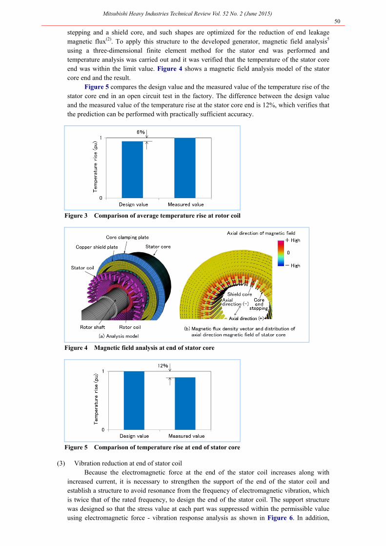
stepping and a shield core, and such shapes are optimized for the reduction of end leakagemagnetic flux(2). To apply this structure to the developed generator, magnetic field analysis5
using a three-dimensional finite element method for the stator end was performed and temperature analysis was carried out and it was verified that the temperature of the stator core end was within the limit value. Figure 4 shows a magnetic field analysis model of the stator core end and the result.
Figure 5 compares the design value and the measured value of the temperature rise of the stator core end in an open circuit test in the factory. The difference between the design valueand the measured value of the temperature rise at the stator core end is 12%, which verifies that the prediction can be performed with practically sufficient accuracy.
Figure 3 Comparison of average temperature rise at rotor coil
Figure 4 Magnetic field analysis at end of stator core
Figure 5 Comparison of temperature rise at end of stator core
(3) Vibration reduction at end of stator coil Because the electromagnetic force at the end of the stator coil increases along with
increased current, it is necessary to strengthen the support of the end of the stator coil and establish a structure to avoid resonance from the frequency of electromagnetic vibration, whichis twice that of the rated frequency, to design the end of the stator coil. The support structure was designed so that the stress value at each part was suppressed within the permissible valueusing electromagnetic force - vibration response analysis as shown in Figure 6. In addition,

Mitsubishi Heavy Industries Technical Review Vol. 52 No. 2 (June 2015) 51
natural frequency analysis was performed in order to make the support structure sufficientlydifferent from the electromagnetic vibration frequency.
Figure 7 compares the design value of the natural frequency of four-node vibration (1st mode) and the measured value in the factory test. This verifies that the natural frequency issufficiently different from the electromagnetic vibration frequency of 120 Hz and that highdesign accuracy with the difference between the design value and the measured value of 5% isattained.
Figure 6 Electromagnetic force - vibration response analysis at end of stator coil
Figure 7 Comparison of natural frequency at end of stator coil (four-node, 1st mode)
3.3 Performance evaluation in factory test
Assembly of the 60 Hz version of the developed generator was completed in the factory inOctober 2013, and the factory test for performance verification was then implemented. As a resultof each test, it was verified that the design specifications were met.
The performance test showed that the field currents at the no-load rated voltage and the three-phase short-circuit rated current conformed to the design values with an uncertainty of 1%. Itwas then verified that the design accuracy of the efficiency and the short-circuit ratio was high.
As a result of the temperature test, it was verified that the stator coil temperature, the stator cooling water temperature, the average rotor coil temperature, the stator core end temperature, andthe shield core temperature were suppressed within the limit values.
The vibration measurement verified that the shaft vibration and the stator coil end vibration during the temperature test were within the limit values.
|4. Development of 900 MVA-class indirect hydrogen cooled generators Figure 8 shows the relation between the stator coil cooling system and the capacity of
turbine generators made by MHPS. Because the amount of heat generated in the generatorincreases along with increase in the generator capacity, small capacity generators (up to 300 MVA)use the indirect air cooling system, medium capacity generators (200 to 500 MVA) use the indirect hydrogen cooling system, and large capacity generators (500 to 2000 MVA) use the direct watercooling system. Among these cooling systems, the indirect hydrogen cooling system does not require incidental equipment including a stator cooling water system and the related piping necessary for the direct water cooling system, and therefore it has the advantage of improvement in operability and maintainability. In addition, hollow conductors for water cooling of the stator coil

Mitsubishi Heavy Industries Technical Review Vol. 52 No. 2 (June 2015) 52
become unnecessary and the cross-sectional area of the conductor can then be enlarged, resulting indecreased loss and enhanced efficiency.
MHPS manufactured and shipped a 500 MVA-class indirect hydrogen cooled generator in 2010, and has been working on an increase of the capacity of indirect hydrogen cooled generators to replace the conventional direct water cooling system of over 500 MVA generators with the indirect hydrogen cooling system. The development status of a 900 MVA-class indirect hydrogen cooled generator is described below.
Figure 8 Relation between stator coil cooling system and generator capacity
4.1 Design principle The cooling performance of the indirect hydrogen cooling system is lower than that of the
direct water cooling system, and therefore the increase of the capacity of the indirect hydrogen cooled generator has the important issues of the enhancement of the cooling performance and thereduction of the loss. Figure 9 shows the main technologies applied to the 900 MVA developedgenerator. Among technologies for the increase of the capacity of indirect hydrogen cooled generators, the high heat transmission insulation system for the enhancement of stator coil coolingperformance is a key technology. This technology is described in 4.2.
Figure 9 Technologies applied to 900 MVA-class indirect hydrogen cooled generator
The 900 MVA developed generator was designed using the latest design tools that had theircalculation accuracy verified with the preceding generator and the 1300 MVA developed generator. In this design process, first the capacity was increased to 600 MVA for both 50 Hz and 60 Hz by enhancing cooling and reducing the loss of the stator and the rotor with the use of the conventional insulation for the stator coil. Next, the capacity was increased by applying the high heat transmission insulation system to the stator coil, and the basic design of the 900 MVA developedgenerator for each of 50 Hz and 60 Hz was then completed with the prediction of satisfying thegenerator specifications and suppressing the temperature and vibration of each part within the limitvalue. Table 2 shows the main specifications. It is estimated that the 900 MVA developedgenerator will attain a high efficiency of 99.0 to 99.1%.

Mitsubishi Heavy Industries Technical Review Vol. 52 No. 2 (June 2015) 53
Table 2 Main specifications of 900 MVA-class indirect hydrogen cooled generator
Developed generator50Hz 60Hz
Capacity (MVA) 880 880 Voltage (kV) 20 21 Current (A) 25403 24194 Power factor 0.85 0.85 Rotation speed (min-1) 3000 3600 Hydrogen gas pressure (MPa-g) 0.52 0.52 Efficiency (%) 99.1 99.0
4.2 High heat transmission insulation system
The stator coil is protected by the insulation layer against the high voltage of several tens ofkilovolts. The thermal conductivity of the insulation layer is about three digits smaller than the conductor. Therefore the improvement of the thermal conductivity of the insulation layer is the keyto the enhancement of the cooling performance.
MHPS developed a high heat transmission insulation system having a thermal conductivity of the insulation layer approximately twice the conventional insulation by adding high thermalconductivity micro filler to the insulation layer.6 In the development process, the physical properties were evaluated, and the electrical characteristics test, mechanical characteristics test, cooling performance test, thermal aging test, voltage endurance test, and thermal cycle test were carried out with the actual manufactured coil. Through the favorable results obtained from thesetests, it was verified that the developed insulation system would be practical. Examples of thespecific test results are described below. (1) Cooling performance
For the evaluation of the cooling performance of the high heat transmission insulation system, the thermal conductivity of the insulation layer was measured first. As shown inFigure 10, the thermal conductivity of the high heat transmission insulation layer was approximately twice the conventional insulation layer.
Figure 10 Measurement result of thermal conductivity of insulation layer
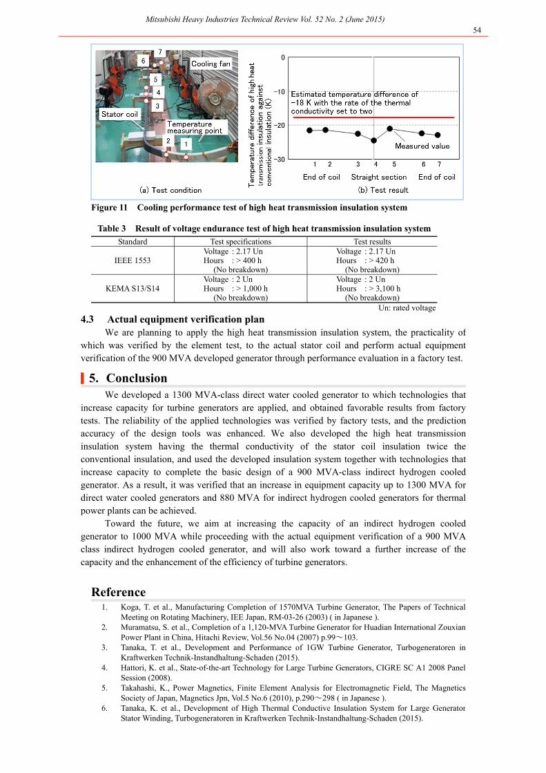
Next, to evaluate the cooling performance of the stator coil, the actual-size coil shown in Figure 11 (a), the conductor temperature was measured when the coil was heated up electrically and cooled with a fan. Figure 11 (b) shows the temperature difference of the highheat transmission insulation against the conductor of the conventional insulation. The measured temperature difference was -20 K or less over the entire length of the stator coil, which waslower than the estimated temperature difference of -18 K with the rate of the thermal conductivity set to two. It was verified by this result that the high thermal conductivityinsulation system, as the stator coil, had sufficient cooling performance.
(2) Voltage endurance test For the evaluation of the insulation characteristics, voltage endurance tests in complying
with the standards of IEEE 1553 and S13/S14 of KEMA, which is a famous Europeancertification body, were implemented, and results that satisfied the standards were obtained as shown in Table 3.
Mitsubishi Heavy Industries Technical Review Vol. 52 No. 2 (June 2015) 54
Figure 11 Cooling performance test of high heat transmission insulation system
Table 3 Result of voltage endurance test of high heat transmission insulation system Standard Test specifications Test results
IEEE 1553 Voltage : 2.17 UnHours : > 400 h
(No breakdown)
Voltage : 2.17 Un Hours : > 420 h
(No breakdown)
KEMA S13/S14 Voltage : 2 UnHours : > 1,000 h
(No breakdown)
Voltage : 2 UnHours : > 3,100 h
(No breakdown) Un: rated voltage
4.3 Actual equipment verification plan We are planning to apply the high heat transmission insulation system, the practicality of
which was verified by the element test, to the actual stator coil and perform actual equipmentverification of the 900 MVA developed generator through performance evaluation in a factory test.
|5. Conclusion We developed a 1300 MVA-class direct water cooled generator to which technologies that
increase capacity for turbine generators are applied, and obtained favorable results from factory tests. The reliability of the applied technologies was verified by factory tests, and the predictionaccuracy of the design tools was enhanced. We also developed the high heat transmissioninsulation system having the thermal conductivity of the stator coil insulation twice the conventional insulation, and used the developed insulation system together with technologies that increase capacity to complete the basic design of a 900 MVA-class indirect hydrogen cooled generator. As a result, it was verified that an increase in equipment capacity up to 1300 MVA fordirect water cooled generators and 880 MVA for indirect hydrogen cooled generators for thermal power plants can be achieved.
Toward the future, we aim at increasing the capacity of an indirect hydrogen cooled generator to 1000 MVA while proceeding with the actual equipment verification of a 900 MVAclass indirect hydrogen cooled generator, and will also work toward a further increase of the capacity and the enhancement of the efficiency of turbine generators.
Reference 1. Koga, T. et al., Manufacturing Completion of 1570MVA Turbine Generator, The Papers of Technical
Meeting on Rotating Machinery, IEE Japan, RM-03-26 (2003) ( in Japanese ). 2. Muramatsu, S. et al., Completion of a 1,120-MVA Turbine Generator for Huadian International Zouxian
Power Plant in China, Hitachi Review, Vol.56 No.04 (2007) p.99~103. 3. Tanaka, T. et al., Development and Performance of 1GW Turbine Generator, Turbogeneratoren in
Kraftwerken Technik-Instandhaltung-Schaden (2015). 4. Hattori, K. et al., State-of-the-art Technology for Large Turbine Generators, CIGRE SC A1 2008 Panel
Session (2008). 5. Takahashi, K., Power Magnetics, Finite Element Analysis for Electromagnetic Field, The Magnetics
Society of Japan, Magnetics Jpn, Vol.5 No.6 (2010), p.290~298 ( in Japanese ). 6. Tanaka, K. et al., Development of High Thermal Conductive Insulation System for Large Generator
Stator Winding, Turbogeneratoren in Kraftwerken Technik-Instandhaltung-Schaden (2015).