Development of HIII Model TMC · 2-2.X-ray CT scan X-ray CT scanner Sectional points groups 3D...
21
1/21 Development of Detailed AM50%ile Hybrid III Dummy FE Model Presented at LS-DYNA Forum, 13 October 2011, Filderstadt (Stuttgart), Germany TOYOTA MOTOR CORPORATION Tatsuya KOMAMURA
Transcript of Development of HIII Model TMC · 2-2.X-ray CT scan X-ray CT scanner Sectional points groups 3D...

1/21
Development ofDetailed AM50%ile Hybrid III
Dummy FE Model
Presented at LS-DYNA Forum, 13 October 2011, Filderstadt (Stuttgart), Germany
TOYOTA MOTOR CORPORATIONTatsuya KOMAMURA

2/21
CONTENTSCONTENTS
1.Background and Objectives
2.Development of Frontal Impact Dummy FE Model
3.Model Validation
4.Discussion
5.Conclusions

3/21
1-1. BackgroundThe dummy’s injury measurements are evaluated in FMVSS 208, such as head G, chest deflection and so on.
FE analysis recently is utilized to predict the dummy responses.
Miyazaki et al. developed a FE flex impactormodel using reverse engineering technique with CT scan measurement.
Developing a fine dummy FE model with the technique is also expected.

4/21
1-2.Objectives
To develop a HybridⅢ AM50%ile dummy model using the reverse engineering technique.
To examine the kinematics and injury responses by comparing to those from the tests.

5/21
2-1.Reverse Engineering・Fine mesh from the geometry data scanned by X ray CT.・Input the experimentally measured material properties and joint stiffness.

6/21
2-2.X-ray CT scan
X-ray CT scanner Sectional points groups 3D geometry (STL)
・Geometry data is obtained with a physical dummyat 1mm scan pitch by TMC-owned X-ray CT scanner. ・Metal and non-metal 2D images are obtained by setting X-ray threshold levels. ・3D geometry is obtained by image reconstruction.
〔Example:Torso〕

7/21
2-3.Mesh GenerationFE mesh is made in detail to represent 3D data w/o omission - Element size: 3-5mm for deformable parts - Skin parts: Meshed with Solid Element
The number of elements
〔Overview〕 〔Section View〕
Part 320Node 450,000ELEMENT 390,000
HybridⅢ AM50%ile FE Model
Skin(Solid)
Rib(Shell
And& Solid)
SpineBox
(Solid)
8/21
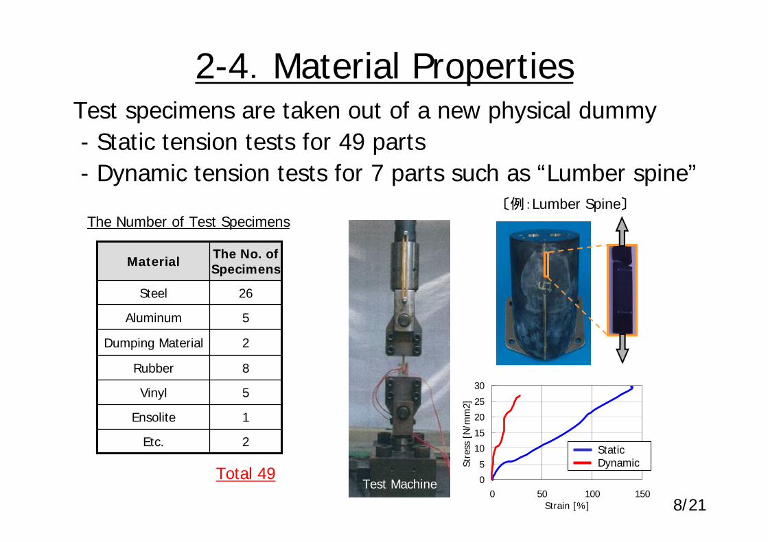
2-4.Material PropertiesTest specimens are taken out of a new physical dummy- Static tension tests for 49 parts- Dynamic tension tests for 7 parts such as “Lumber spine”
The No. of SpecimensMaterial
2Etc.
1Ensolite
5Vinyl
8Rubber
2Dumping Material
5Aluminum
26Steel
The Number of Test Specimens
Total 49
〔例:Lumber Spine〕
Test MachineSt
ress
[N
/mm
2]0
5
10
15
20
25
30
0 50 100 150Strain [%]
Static Dynamic

05
1015202530354045
Force[N]
Freq
uenc
y[%
]
2 3 4 5 6 7 8 9 10 111
9/21
2-5. Mechanical Properties- Joint stiffness is measured at 27 joints - Ave. value from 90 data obtained at each joint is applied
〔Example〕
Measurement of Shoulder Joint Measurement Result
F
DummyAM50
Push Pull Gauge Shoulder
Joint
320mm
Ave.

Assembly
Head Head Drop Test ○
Neck Pendulum Test (+) ○
Neck Pendulum Test (-) ○
Thorax Impact Test (Low Speed) ○
Rib Static compression Test ○
Thorax Dynamic Seatbelt Test ○
Pelvis Hip Joint-Femur Flexion Test ○
Knee Impact Test ○
Knee Slide Impact Test ○
Upper Foot Impact Test - without Shoe ○
Lower Foot Impact Test - without Shoe ○
Lower Foot Impact Test - with Shoe ○
Sled All Full Lap Sled Test ○
Com
porn
ent
Leg
Neck
Thorax Thorax Impact Test ○
Standard Certification Test Additional Test
Knee
10/21
3-1.Model Validation- 10 certification tests based on FMVSS208 are conducted- Tests for chest characteristics and sled test are added
Result Result
11/21
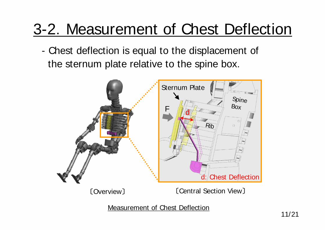
3-2.Measurement of Chest Deflection- Chest deflection is equal to the displacement of
the sternum plate relative to the spine box.
Measurement of Chest Deflection
〔Overview〕 〔Central Section View〕
F d
d: Chest Deflection
Spine Box
Rib
Sternum Plate

12/21
3-3.Dynamic Seatbelt Loading- Seatbelt tension loading on the chest fixed spine rigidly- 2 tests of different belt path on the chest are evaluated
Test Condition
VV
Comparison of Seatbelt Path
〔Path B〕〔Path A〕
FixFix
Tension velocity is aimed to simulate chest deflection rate in crash tests.
13/21
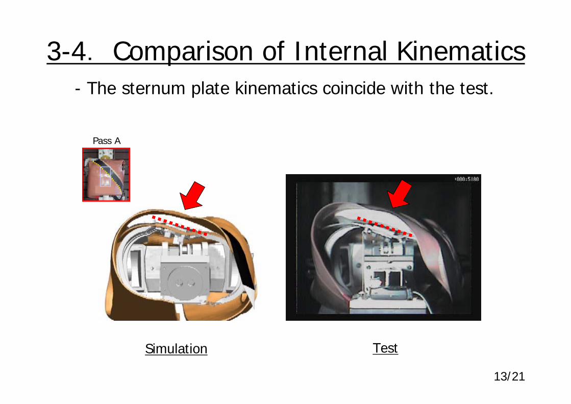
3-4. Comparison of Internal Kinematics
Simulation Test
- The sternum plate kinematics coincide with the test.
Pass A

0 0.02 0.04 0.06 0.08Time [ms]
1.2
1.0
0.8
0.6
0.4
0.2
0
Rat
io
14/21
3-5.Comparison of Chest Deflection
Chest Deflection (Test Max. Value Original Pass=1.0)
〔Path A〕
Simulation Test
〔Path B〕
Simulation Test
Time [sec] Time [sec]
・Chest deflection is well coincide with the test in both2 path conditions.
0
8
17
25
33
42
50
0 0.02 0.04 0.06 0.08Time [ms]
1.2
1.0
0.8
0.6
0.4
0.2
0
Rat
io

15/21
3-6.Frontal Full Lap Sled Test
Simulation Model
Not AvailableInstrument Panel
Not AvailableAirbag
AvailableSeatbelt
ActivatedPretensioner
4 kNForce Limiter
PassengerOccupant
48 km/hImpact Velocity
Simulation Condition
・Sled condition: 48km/h Full lap frontal crash・Restraint system: Seat, Seatbelt with force limiter

16/21
Simulation Test
3-7. Comparison of Kinematics- Kinematics of FE model correlates to test.

17/21
3-8.Comparison of Chest Def.- Chest deflection of FE model correlate to test data.
Chest Deflection
Acce
lera
tion
(FE/
TEST
Max
. Val
ue)
080
160240320400480
Acc
eler
atio
n [m
/s2 ] 1.21.00.80.60.40.2
0
Def
lect
ion
(FE/
TEST
Max
. Val
ue)
Simulation Test
#1 #2
0 0.02 0.04 0.06 0.08 0.1 0.12
Time [sec]
Pretensioner Constant Def. Pelvis Rebound

18/21
4-1.Kinematics・0~50ms:Translational movement bet. chest and pelvis・50ms~:Forward movement with rotation in thorax
Displacement of Thorax and Pelvis
0 ms 50 ms 80 ms
050
100150200250300
0 0.02 0.04 0.06 0.08 0.1 0.12Time [sec]
Dis
plac
emen
t [m
m]
ThoraxPelvis
Translation Rotation
0.05
#1 #2
19/21
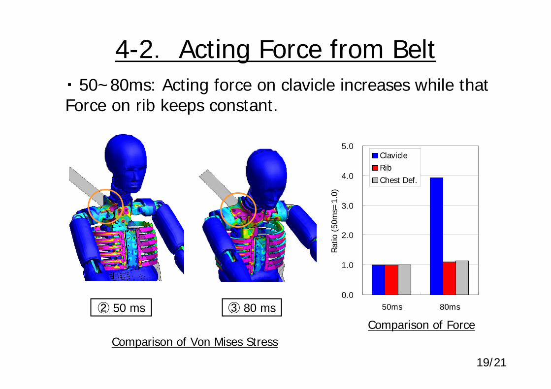
② 50 ms ③ 80 ms
・ 50~80ms: Acting force on clavicle increases while that Force on rib keeps constant.
Comparison of Von Mises StressComparison of Force
0.0
1.0
2.0
3.0
4.0
5.0
50ms 80ms
Ratio
(50
ms=
1.0)
ClavicleRibChest Def.
4-2. Acting Force from Belt

20/21
5.Conclusions
(1) Developed a detailed FE HIII Dummy model with reverse engineering using X-ray CT scans.
(2) Material properties were studied by cutting out test specimens from dummy component parts and performed static and dynamic tests.
(3) The force response of the developed FE model was verified in comparison tests and found to be consistent with the results obtained from a physical dummy.
(4) It was concluded that this detailed FE model is effective for analyzing deformation and force transfer inside the dummy in crash tests.

Thank you for your attention.
21/21