Development of Free-standing Rack Seismic Evaluation … · Mitsubishi Heavy Industries Technical...
5
Mitsubishi Heavy Industries Technical Review Vol. 53 No. 4 (December 2016) 103 *1 Vibration Research Department, Research & Innovation Center *2 Chief Staff Manager, Vibration Research Department, Research & Innovation Center *3 Chief Staff Manager, Vibration Research Department, Research & Innovation Center *4 Manager, Nuclear Plant Component Designing Department, Nuclear Energy Systems Division, Energy & Environment *5 Nuclear Plant Component Designing Department, Nuclear Energy Systems Division, Energy & Environment Development of Free-standing Rack Seismic Evaluation Method AKIHISA IWASAKI *1 YOSHITSUGU NEKOMOTO *2 HIDEYUKI MORITA *3 JUNICHI KISHIMOTO *4 KATSUHIKO TANIGUCHI *5 YU TAKAKI *5 The spent fuel taken out of a reactor in a nuclear power plant is temporarily stored in a spent fuel rack until it is carried out to an intermediate storage facility or a reprocessing facility. The spent fuel rack requires high earthquake resistance. The free-standing rack has no supporting members around it and disperses seismic energy with friction by sliding, and the water around the rack reduces the response. Therefore, it can be expected to provide high earthquake resistance. In consideration of three-dimensional behavior, collisions and fluid-structure interaction accompanied by sliding and rocking during a large excitation, the seismic evaluation method for the free-standing rack was established, and its validity was confirmed through a comparison with the results of the full-scale excitation test conducted at E-Defense*. In this report, the seismic evaluation method for the free-standing rack is described. * One of the world's largest shake tables at the three-dimensional full-scale earthquake testing facility at the Hyogo Earthquake Engineering Research Center of the National Research Institute for Earth Science and Disaster Resilience. | 1. Introduction With the occurrence of major earthquakes in recent years, it is important that the major equipment of nuclear power plants has high earthquake resistance, and spent fuel racks which can withstand major earthquakes are in demand. In order to meet this demand, the development of free standing-type spent fuel racks (free-standing rack) has been conducted. The free-standing rack (Figure 1) has no supporting members around it and is placed directly on the spent fuel pit floor. Therefore, it is not necessary to consider the proof stress of supporting members, and in the event of an earthquake, the earthquake input to the free-standing rack itself is reduced by the sliding of the free-standing rack, in contrast to a wall supporting-type or floor supporting-type rack. In addition, the free-standing rack disperses seismic energy with friction by sliding, and the water around the rack reduces the response. As such, this design method can be expected to contribute to the development of higher earthquake resistance. The rack cells of the free-standing rack are loaded with spent fuel. In the event of an earthquake, the fuel vibrates in the rack cell, the fuel and the rack cell collide, and the free-standing rack not only slides but also rocks (the phenomenon that the rack legs lift up). Therefore, for the design of the free-standing rack, it is necessary to establish an analysis method by which three-dimensional nonlinear events such as sliding, rocking and collisions can be evaluated. The purposes of this research are to establish an seismic evaluation method for the free-standing rack, to check the validity of the seismic evaluation method through an excitation test for a full-scale free-standing rack, and to realize the prospect for practical use.
Transcript of Development of Free-standing Rack Seismic Evaluation … · Mitsubishi Heavy Industries Technical...

Mitsubishi Heavy Industries Technical Review Vol. 53 No. 4 (December 2016) 103
*1 Vibration Research Department, Research & Innovation Center *2 Chief Staff Manager, Vibration Research Department, Research & Innovation Center *3 Chief Staff Manager, Vibration Research Department, Research & Innovation Center *4 Manager, Nuclear Plant Component Designing Department, Nuclear Energy Systems Division, Energy & Environment *5 Nuclear Plant Component Designing Department, Nuclear Energy Systems Division, Energy & Environment
Development of Free-standing Rack Seismic Evaluation Method
AKIHISA IWASAKI*1 YOSHITSUGU NEKOMOTO*2
HIDEYUKI MORITA*3 JUNICHI KISHIMOTO*4
KATSUHIKO TANIGUCHI*5 YU TAKAKI*5
The spent fuel taken out of a reactor in a nuclear power plant is temporarily stored in a spent
fuel rack until it is carried out to an intermediate storage facility or a reprocessing facility. Thespent fuel rack requires high earthquake resistance. The free-standing rack has no supporting members around it and disperses seismic energy with friction by sliding, and the water around therack reduces the response. Therefore, it can be expected to provide high earthquake resistance. In consideration of three-dimensional behavior, collisions and fluid-structure interactionaccompanied by sliding and rocking during a large excitation, the seismic evaluation method for the free-standing rack was established, and its validity was confirmed through a comparison with the results of the full-scale excitation test conducted at E-Defense*. In this report, the seismicevaluation method for the free-standing rack is described.
* One of the world's largest shake tables at the three-dimensional full-scale earthquake testing facility at the Hyogo Earthquake Engineering Research Center of the National Research Institute for Earth Science andDisaster Resilience.
|1. Introduction With the occurrence of major earthquakes in recent years, it is important that the major
equipment of nuclear power plants has high earthquake resistance, and spent fuel racks which canwithstand major earthquakes are in demand. In order to meet this demand, the development of freestanding-type spent fuel racks (free-standing rack) has been conducted. The free-standing rack (Figure 1) has no supporting members around it and is placed directly on the spent fuel pit floor.Therefore, it is not necessary to consider the proof stress of supporting members, and in the event of an earthquake, the earthquake input to the free-standing rack itself is reduced by the sliding of the free-standing rack, in contrast to a wall supporting-type or floor supporting-type rack. In addition, the free-standing rack disperses seismic energy with friction by sliding, and the water around the rack reduces the response. As such, this design method can be expected to contribute to the development of higher earthquake resistance. The rack cells of the free-standing rack are loaded with spent fuel. In the event of an earthquake, the fuel vibrates in the rack cell, the fuel and the rackcell collide, and the free-standing rack not only slides but also rocks (the phenomenon that the racklegs lift up). Therefore, for the design of the free-standing rack, it is necessary to establish an analysis method by which three-dimensional nonlinear events such as sliding, rocking andcollisions can be evaluated.
The purposes of this research are to establish an seismic evaluation method for the free-standing rack, to check the validity of the seismic evaluation method through an excitation test for a full-scale free-standing rack, and to realize the prospect for practical use.

Mitsubishi Heavy Industries Technical Review Vol. 53 No. 4 (December 2016) 104
Figure 1 Free-standing rack The free-standing rack is surrounded by the outer peripheral boards and the legs have a rotation mechanism to prevent stress from being concentrated due to rocking.
|2. Seismic analysis method A seismic analysis method intended for three-dimensional nonlinear behaviors including
sliding and collisions was established, and a vibration test using a shake table was conducted forthe full-scale free-standing rack in water for the first time anywhere in the world. As a result, it wasconfirmed that the sliding and rocking behaviors, collision load, etc., in the full-scale test can be simulated by the analysis, which allows the evaluation of the structural integrity of the free-standing rack against major earthquakes. 2.1 Analysis model
The vibration responses of the free-standing rack are three-dimensional nonlinear behaviors such as sliding, rotation and collisions as shown in Figure 2. An outline of the analysis model is shown in Figure 2. The free-standing rack and fuel are modeled by one beam, and the fluid structure interaction between the free-standing rack and the pit and between the fuel and the rackcell is taken into account. Also considered are collisions (spring, damping, gap) and friction between the free-standing rack legs and the pit floor and between the fuel and the base plate, as well as collisions (spring, damping, rattling) between the fuel and the rack cell. For the seismicanalysis of the free-standing rack, Adams (MSC Software) was used as the Multibody Dynamicssoftware.
Figure 2 Outline of analysis model of free-standing rack The free-standing rack and fuel assembly are modeled by one uniform beam, and the collision part was simulated by a spring and damper.
Mitsubishi Heavy Industries Technical Review Vol. 53 No. 4 (December 2016) 105
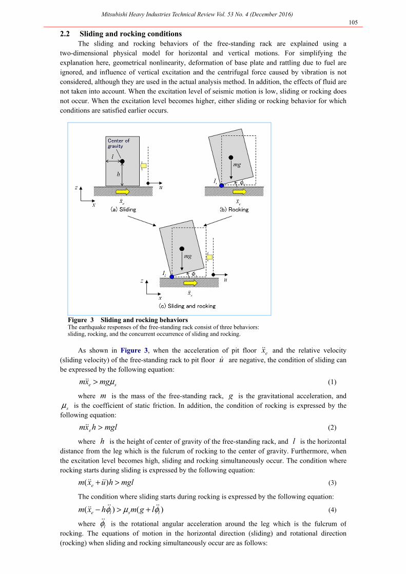
2.2 Sliding and rocking conditions The sliding and rocking behaviors of the free-standing rack are explained using a
two-dimensional physical model for horizontal and vertical motions. For simplifying theexplanation here, geometrical nonlinearity, deformation of base plate and rattling due to fuel are ignored, and influence of vertical excitation and the centrifugal force caused by vibration is not considered, although they are used in the actual analysis method. In addition, the effects of fluid arenot taken into account. When the excitation level of seismic motion is low, sliding or rocking doesnot occur. When the excitation level becomes higher, either sliding or rocking behavior for whichconditions are satisfied earlier occurs.
Figure 3 Sliding and rocking behaviors The earthquake responses of the free-standing rack consist of three behaviors: sliding, rocking, and the concurrent occurrence of sliding and rocking.
As shown in Figure 3, when the acceleration of pit floor ex&& and the relative velocity (sliding velocity) of the free-standing rack to pit floor u& are negative, the condition of sliding can be expressed by the following equation:
se mgxm μ>&& (1)
where m is the mass of the free-standing rack, g is the gravitational acceleration, and sμ is the coefficient of static friction. In addition, the condition of rocking is expressed by the
following equation:
mglhxm e >&& (2)
where h is the height of center of gravity of the free-standing rack, and l is the horizontal distance from the leg which is the fulcrum of rocking to the center of gravity. Furthermore, when the excitation level becomes high, sliding and rocking simultaneously occur. The condition whererocking starts during sliding is expressed by the following equation:
mglhuxm e >+ )( &&&& (3)
The condition where sliding starts during rocking is expressed by the following equation:
)()( lsle lgmhxm φμφ &&&&&& +>− (4)
where lφ&& is the rotational angular acceleration around the leg which is the fulcrum ofrocking. The equations of motion in the horizontal direction (sliding) and rotational direction (rocking) when sliding and rocking simultaneously occur are as follows:

Mitsubishi Heavy Industries Technical Review Vol. 53 No. 4 (December 2016) 106
lle mhlgmuxm φφμ &&&&&&&& ++=+ )()( (5)
huxmmglI ell )( &&&&&& ++−=φ (6)
where μ is the coefficient of kinetic friction, and lI is the moment of rotatory inertia. When the excitation is large, the mixing behavior of sliding and rocking occurs. In that case, thebehavior of the free-standing rack will be calculated based on equations (5) and (6). In actual fact,it needs to be considered in three dimensions, and it is also affected by geometrical nonlinearity andelastic response, resulting in a complicated calculation. 2.3 Full-scale excitation test
The three-dimensional full-scale earthquake testing facility (E-Defense) at the Hyogo Earthquake Engineering Research Center of the National Research Institute for Earth Science andDisaster Resilience was used to conduct the seismic test for the full-scale free-standing rack placed in a large pool filled with water. An outline of the seismic test is shown in Figure 4. The free-standing rack test body is composed of 7×10 rack cells, has the dimensions of 4.5 m in height,2 m in width and 3 m in length, and weighs about 70 tons with the mock-up of fuel being loaded. The legs are structured to be rotatable to prevent stress from being concentrated when rockingoccurs. The excitation seismic wave divided into short period, medium period, and long period asshown in Figure 5 was used. Although the free-standing rack has no frequency response to seismic motion, the results showed that the response was small in the short-period wave and medium-period wave, while the response was clear in the long-period wave in which the sliding time (during which the acceleration is large) is long and the excitation displacement is large, as shown in Figure 6.
Figure 4 Outline of seismic test Using E-Defense, the seismic test for the full-scale free-standing rack was conducted.
Figure 5 Excitation seismic wave A seismic wave divided by short period, medium period and long period was used in the seismic test.
Figure 6 Test results (excitation in one horizontal direction) The free-standing rack sliding displacement and leg uplift displacement in the seismic test are shown.

Mitsubishi Heavy Industries Technical Review Vol. 53 No. 4 (December 2016) 107
2.4 Comparison between test and analysis results The test and analysis results for the long-period seismic wave excitation which exhibited a
clear response are shown in Figure 7. The test results and the analysis results for sliding displacement, leg uplift displacement and loading agreed, and the validity of the analysis wasconfirmed.
Figure 7 Comparison between test and analysis (simultaneous excitation in three directions)
The sliding displacement, leg uplift displacement and leg loading in the seismic wave excitation test and the analysis are shown.
|3. Conclusion This report summarizes the results of the joint research conducted by five Japanese electric
companies operating pressurized water reactor nuclear power plants, and here we express ourgratitude for the valuable advice received from the parties concerned.
The conclusion of this article is as follows: (1) It was confirmed that the seismic analysis of the free-standing rack using the mechanism
analysis can evaluate sliding displacement, leg uplift displacement and loadingaccompanied with the sliding and rocking of the free-standing rack.
(2) Through a comparison of the sliding displacement, leg uplift displacement and loadobtained in the full-scale excitation test, the validity of the analysis evaluation methodwas verified.
(3) Since it was confirmed that the free-standing rack can be evaluated by seismic analysis, it was also confirmed that an actual free-standing rack can be achieved, and a certain prospect toward the practical use of the free-standing rack was obtained.
References 1. Iwasaki,A., Nekomoto,Y., Morita,H., Taniguchi,K., Okuno,D.,Matsuoka,T. and Chigusa,N., Practical
research of free standing rack (Seismic experiment study on full scale free standing rack), Transactions ofthe Japan Society of Mechanical Engineers (in Japanese), Vol.81, No.831 (2015), DOI :
10.1299/transjsme.15-00153. 2. Iwasaki,A., Nekomoto,Y., Morita,H., Taniguchi,K., Okuno,D.,Matsuoka,T. and Chigusa,N., Practical
research of free standing rack (Development of seismic evaluation method), Transactions of the Japan Society of Mechanical Engineers (in Japanese), Vol.81, No.831 (2015), DOI :
10.1299/transjsme.15-00212.2. 3. Development of Free Standing Spent Fuel Rack, Mitsubishi Heavy Industries Technical Review Vol. 43
No. 4 (2006)