Development of fast controls for Beam Wire Scanner at ... of fast controls for Beam Wire Scanner at...
21
Development of fast controls for Beam Wire Scanner at SuperKEKB Anindya Roy Variable Energy Cyclotron Centre Dept. of Atomic Energy, India
Transcript of Development of fast controls for Beam Wire Scanner at ... of fast controls for Beam Wire Scanner at...

Development of fast controls forBeam Wire Scanner
at SuperKEKB
Anindya Roy
Variable Energy Cyclotron CentreDept. of Atomic Energy, India
Anindya Roy
Variable Energy Cyclotron CentreDept. of Atomic Energy, India

What is WireWhat is Wire--scanner?scanner? Used for Non-destructive monitoring of beam
profile
A frame holding 100µm Tungsten wireforming X, Y & U wires perpendicular to beam
A stepper motor drive to move the frameinside beam line
A PMT with Plastic Scintillator to detectBremsstrahlung emitted due to interactionof wire with Beam
A control & data acquisition system
A set of three (atleast) wire-scanner formeasuring beam emmittance & Twissparameter for optics matching
6/14/2012 2Fast Controls for Beam Wire Scanner
Used for Non-destructive monitoring of beamprofile
A frame holding 100µm Tungsten wireforming X, Y & U wires perpendicular to beam
A stepper motor drive to move the frameinside beam line
A PMT with Plastic Scintillator to detectBremsstrahlung emitted due to interactionof wire with Beam
A control & data acquisition system
A set of three (atleast) wire-scanner formeasuring beam emmittance & Twissparameter for optics matching
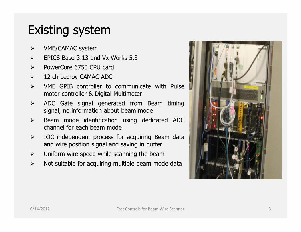
Existing systemExisting system VME/CAMAC system
EPICS Base-3.13 and Vx-Works 5.3
PowerCore 6750 CPU card
12 ch Lecroy CAMAC ADC
VME GPIB controller to communicate with Pulsemotor controller & Digital Multimeter
ADC Gate signal generated from Beam timingsignal, no information about beam mode
Beam mode identification using dedicated ADCchannel for each beam mode
IOC independent process for acquiring Beam dataand wire position signal and saving in buffer
Uniform wire speed while scanning the beam
Not suitable for acquiring multiple beam mode data
6/14/2012 3Fast Controls for Beam Wire Scanner
VME/CAMAC system
EPICS Base-3.13 and Vx-Works 5.3
PowerCore 6750 CPU card
12 ch Lecroy CAMAC ADC
VME GPIB controller to communicate with Pulsemotor controller & Digital Multimeter
ADC Gate signal generated from Beam timingsignal, no information about beam mode
Beam mode identification using dedicated ADCchannel for each beam mode
IOC independent process for acquiring Beam dataand wire position signal and saving in buffer
Uniform wire speed while scanning the beam
Not suitable for acquiring multiple beam mode data
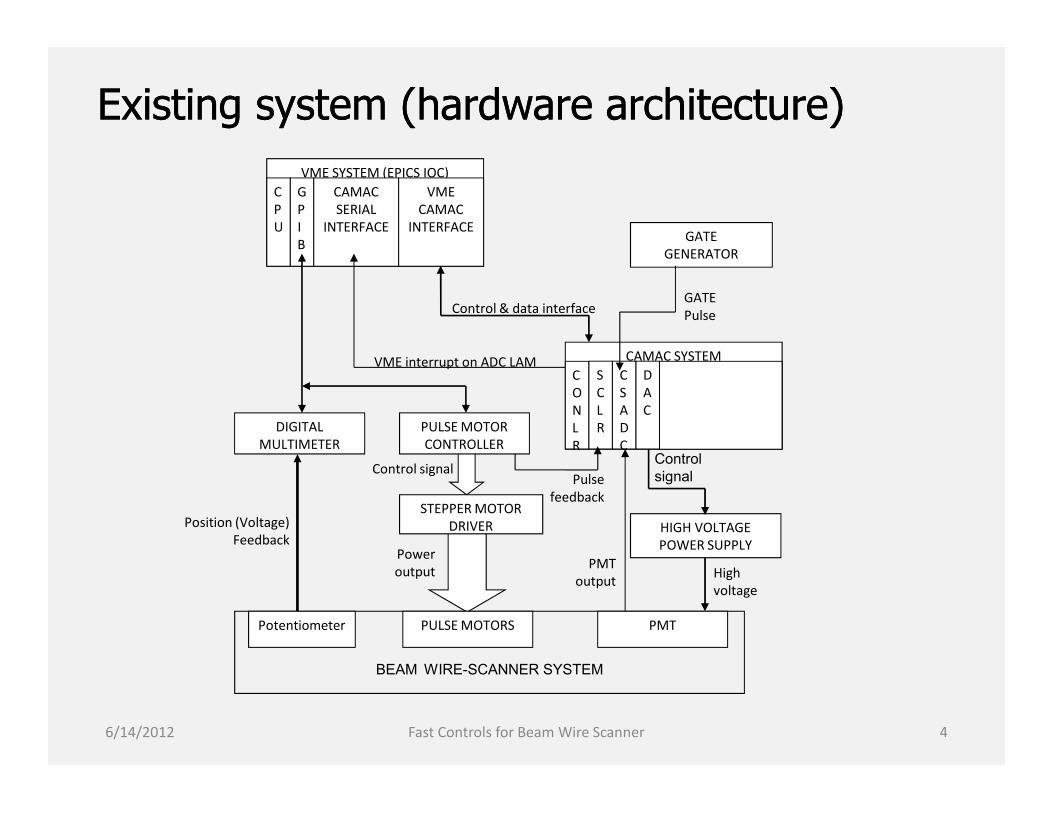
Existing system (hardware architecture)Existing system (hardware architecture)VME SYSTEM (EPICS IOC)
CPU
GPIB
CAMACSERIAL
INTERFACE
VMECAMAC
INTERFACE
CAMAC SYSTEMCONLR
SCLR
CSADC
DAC
GATEGENERATOR
VME interrupt on ADC LAM
GATEPulseControl & data interface
6/14/2012 4Fast Controls for Beam Wire Scanner
CONLR
SCLR
CSADC
DAC
PULSE MOTORCONTROLLER
DIGITALMULTIMETER
BEAM WIRE-SCANNER SYSTEM
STEPPER MOTORDRIVER
PULSE MOTORS
HIGH VOLTAGEPOWER SUPPLY
PMToutput
Pulsefeedback
Control signal
Poweroutput
Position (Voltage)Feedback
Controlsignal
Highvoltage
PMTPotentiometer

Existing system (software architecture)Existing system (software architecture)USER INTERFACE (SAD)
EPICS (3.13) IOC•IT CONTROL THE PROCESS AND ACQUIREDATA FROM ALL SIGNNAL SOURCES•IT READS THE WHOLE EVENT QUEUE ATA TIME AND STORE THE DATA AS ASPECIAL WAVE FORM RECORD•IT SENDS THE DATA TO USER INTERFACEUSING CA PROTOCOL
CAMAC DAQ THREAD•IT RUNS AS AN INDEPENDENTAPPLICATION•IT CREATES EVENT QUEUE MEMORYUSING USER SPECIFIED CONFIGURATION•IT WRITES SCALER, BPM AND WS ADCDATA, ON LAM INTERRUPT OF ADC, ASONE EVENT INTO THE EVENT QUEUE
VxWorks-5.3
6/14/2012 5Fast Controls for Beam Wire Scanner
EPICS (3.13) IOC•IT CONTROL THE PROCESS AND ACQUIREDATA FROM ALL SIGNNAL SOURCES•IT READS THE WHOLE EVENT QUEUE ATA TIME AND STORE THE DATA AS ASPECIAL WAVE FORM RECORD•IT SENDS THE DATA TO USER INTERFACEUSING CA PROTOCOL
CAMAC DAQ THREAD•IT RUNS AS AN INDEPENDENTAPPLICATION•IT CREATES EVENT QUEUE MEMORYUSING USER SPECIFIED CONFIGURATION•IT WRITES SCALER, BPM AND WS ADCDATA, ON LAM INTERRUPT OF ADC, ASONE EVENT INTO THE EVENT QUEUE
EVENT RING BUFFER (GLOBAL MEMORY)EVENT - 0EVENT – 1
…..EVENT - N
EVENT - x
n X SCALER m X BPM p X WS
Why is the new controls for WireWhy is the new controls for Wire--scanner?scanner? 8 Gev LINAC, simultaneously, injects of e- and e+ beam of different characteristics
into
KEKB high-energy ring (HER) – 8.0 GeV, 2nC KEKB low-energy ring (LER) – 3.5 GeV, 2nC Photon Factory (PF) – 2.5 GeV, 0.1nC PF/AR – 3.0 GeV, 0.1nC
The operation of all equipments along BT are synchronized by LINAC Timingsystem for simultaneous injection
A wire-scanner data acquisition system, synchronized with Timing system, canmeasure beam profiles of multiple beam modes simultaneously in a single run
Identification of beam modes can be done using timing information available fromtimimg system
Simultaneous measurement reduces measurement time and hence improves theoverall efficiency of the transport line
May help in PF and PF/AR beam studies without degradation of luminosity atKEKB!
6/14/2012 6Fast Controls for Beam Wire Scanner
8 Gev LINAC, simultaneously, injects of e- and e+ beam of different characteristicsinto
KEKB high-energy ring (HER) – 8.0 GeV, 2nC KEKB low-energy ring (LER) – 3.5 GeV, 2nC Photon Factory (PF) – 2.5 GeV, 0.1nC PF/AR – 3.0 GeV, 0.1nC
The operation of all equipments along BT are synchronized by LINAC Timingsystem for simultaneous injection
A wire-scanner data acquisition system, synchronized with Timing system, canmeasure beam profiles of multiple beam modes simultaneously in a single run
Identification of beam modes can be done using timing information available fromtimimg system
Simultaneous measurement reduces measurement time and hence improves theoverall efficiency of the transport line
May help in PF and PF/AR beam studies without degradation of luminosity atKEKB!

LINAC Timing systemLINAC Timing system MRF’s series-230 Event Generator/Receiver
114.24 MHz event rate
Multi/Single mode fiber connectivity
Timing precision < 10ps
20msec Beam switching
Control approx. 1000 devices in LINAC
Every pulse (20msec) corresponds a beam mode
10 different defined beam modes
One beam pulse contains several event codes
Atleast one Main event code and a preparation code
50 defined event codes
Main event code and preparation event code are in sequence
Main event triggers timing signal
Preparation event trigger software to exchange analog & delay parameters
Total number of receiver: 17 (+ 1)Reference:
“Timing system towards SuperKEKB controls “ – Kazuro Furukawa, EPICS Collaboration Meeting, NSRRC, June 2011
6/14/2012 7Fast Controls for Beam Wire Scanner
MRF’s series-230 Event Generator/Receiver
114.24 MHz event rate
Multi/Single mode fiber connectivity
Timing precision < 10ps
20msec Beam switching
Control approx. 1000 devices in LINAC
Every pulse (20msec) corresponds a beam mode
10 different defined beam modes
One beam pulse contains several event codes
Atleast one Main event code and a preparation code
50 defined event codes
Main event code and preparation event code are in sequence
Main event triggers timing signal
Preparation event trigger software to exchange analog & delay parameters
Total number of receiver: 17 (+ 1)Reference:
“Timing system towards SuperKEKB controls “ – Kazuro Furukawa, EPICS Collaboration Meeting, NSRRC, June 2011

New systemNew system Emerson MVME5500 CPU card, EPICS Base-3.14.12.1 and Vx-works 6.8 combination
VME based ADC (14bit, 15µsec conversion time), Scaler and DAC hardware.
MRF’s event receiver module (VME-EVR-230RF) - synchronizing the data acquisitionprocess with LINAC timing system
A LAN/GPIB converter to communicate with Pulse motor controller (PMC) and DigitalMultimeter (DMM) for control and data acquisition.
ADC Gate generated by event receiver – less complicated hardware setup
Multispeed wire movement to minimize time of scan and maximize useful data
Options to user for selecting beam modes for data acquisition
Application specific EPICS record to retain data format for SAD user interface
Installed at Sector 5 of LINAC BT
6/14/2012 8Fast Controls for Beam Wire Scanner
Emerson MVME5500 CPU card, EPICS Base-3.14.12.1 and Vx-works 6.8 combination
VME based ADC (14bit, 15µsec conversion time), Scaler and DAC hardware.
MRF’s event receiver module (VME-EVR-230RF) - synchronizing the data acquisitionprocess with LINAC timing system
A LAN/GPIB converter to communicate with Pulse motor controller (PMC) and DigitalMultimeter (DMM) for control and data acquisition.
ADC Gate generated by event receiver – less complicated hardware setup
Multispeed wire movement to minimize time of scan and maximize useful data
Options to user for selecting beam modes for data acquisition
Application specific EPICS record to retain data format for SAD user interface
Installed at Sector 5 of LINAC BT

New system (architecture)New system (architecture)
VME SYSTEM (EPICS IOC)C
P
U
SCLR
CSADC
D
A
C
EVR
Events
GATEpulse
EVENT GENERATOR
VME interrupt
LAN/GPIB Gateway
Control LAN
6/14/2012 9Fast Controls for Beam Wire Scanner
DIGITAL MULTI-METER
STEPPER MOTORDRIVER
STEPPER MOTORS
HIGH VOLTAGEPOWER SUPPLY
PMT output
Pulse feedbackControl signal
Power output
Position (Voltage) Feedback
Control signal
High voltage
STEPPER MOTORCONTROLLER
MAG. SCALE PMT
BEAM WIRE-SCANNER SYSTEM

Event ReceiverEvent Receiver Basic feature
Manufacturer – Micro Research Finland, Model - VME-EVR-230RF
Bit rate 1.0 to 2.5 Gbps, event clock rate 50 MHz to 125 MHz
Four programmable front panel TTL outputs
Two front panel TTL inputs
Three differential CML pattern outputs capable of RF recovery
Two universal I/O slots
Rear I/O
Jitter typically < 15 ps rms for TTL outputs, < 5 ps rms for CML outputs
Support VME64x CR/CSR addressing mode
EPICS device support Already available at EPICS Hardware support inventory (mrfioc2-2.0.0.tar.gz)
(http://sourceforge.net/projects/epics/files/mrfioc2/)
As current EPICS version does not support CR/CSR addressing mode in OSindependent manner, hence devLib2 module (devlib2-2.2.tar.gz)(http://sourceforge.net/projects/epics/files/devlib2/)
EPICS MSI tool to build the above modules (msi1-5.tar.gz)(http://www.aps.anl.gov/epics/extensions/msi/index.php)
6/14/2012 10Fast Controls for Beam Wire Scanner
Basic feature Manufacturer – Micro Research Finland, Model - VME-EVR-230RF
Bit rate 1.0 to 2.5 Gbps, event clock rate 50 MHz to 125 MHz
Four programmable front panel TTL outputs
Two front panel TTL inputs
Three differential CML pattern outputs capable of RF recovery
Two universal I/O slots
Rear I/O
Jitter typically < 15 ps rms for TTL outputs, < 5 ps rms for CML outputs
Support VME64x CR/CSR addressing mode
EPICS device support Already available at EPICS Hardware support inventory (mrfioc2-2.0.0.tar.gz)
(http://sourceforge.net/projects/epics/files/mrfioc2/)
As current EPICS version does not support CR/CSR addressing mode in OSindependent manner, hence devLib2 module (devlib2-2.2.tar.gz)(http://sourceforge.net/projects/epics/files/devlib2/)
EPICS MSI tool to build the above modules (msi1-5.tar.gz)(http://www.aps.anl.gov/epics/extensions/msi/index.php)

Event Receiver (configuration)Event Receiver (configuration) EPICS device driver configuration (Different experience from usual VME device configuration!)
Setting up module (IOC initialisation)
mrmEvrSetupVME(NAME, SlotNo, MapAddr, IntrLevel, IntrVectorAddr)
NOT Identified by SLOT No, but by NAME - different from usual EPICS VME device support style!
Each feature (register) is accessed by “Module name:Feature name” (OBJ) and property name (PROP) fields
e.g. field(OUT , "@OBJ=EVR1:Pul0, PROP=Delay") => writing into register
field(INP , "@OBJ=EVR1:Pul0, PROP=Delay") => reading from register
Little difficult to trace NAME of each register, hence better to copy and modify sample records!!
Four record types – ai, ao, longout & longin
Four device types (DTYP)
“Obj Prop uint32” – for longin & longout records
“Obj Prop double” – for ai & ao records
“EVR Pulser Mapping” – for mapping Event codes to pulse generator (longout record)
“EVR Event” – for mapping Event codes to EPICS Event (longout record)
Important properties to configure Enabling the module - field(OUT , "@OBJ=EVR1, PROP=Enable")
Setting up Clock - field(OUT , "@OBJ=EVR1, PROP=Clock")
Setting up Time stamp source - field(OUT , "@OBJ=EVR1, PROP=Timestamp Clock")
Mapping front panel output to pulse generator - field( OUT , "@OBJ=EVR1:FrontOut0, PROP=Map")
Enabling & Configuring pulse generator (i.e. delay, width, polarity) - field(OUT , "@OBJ=EVR1:Pul0, PROP=Polarity")
Mapping timing event to pulse generator - field( OUT , "@OBJ=EVR1:Pul0, Func=$(F=Trig)")
Mapping timing event to EPICS Event - field(OUT , "@OBJ=EVR1,Code=31")
6/14/2012 11Fast Controls for Beam Wire Scanner
EPICS device driver configuration (Different experience from usual VME device configuration!) Setting up module (IOC initialisation)
mrmEvrSetupVME(NAME, SlotNo, MapAddr, IntrLevel, IntrVectorAddr)
NOT Identified by SLOT No, but by NAME - different from usual EPICS VME device support style!
Each feature (register) is accessed by “Module name:Feature name” (OBJ) and property name (PROP) fields
e.g. field(OUT , "@OBJ=EVR1:Pul0, PROP=Delay") => writing into register
field(INP , "@OBJ=EVR1:Pul0, PROP=Delay") => reading from register
Little difficult to trace NAME of each register, hence better to copy and modify sample records!!
Four record types – ai, ao, longout & longin
Four device types (DTYP)
“Obj Prop uint32” – for longin & longout records
“Obj Prop double” – for ai & ao records
“EVR Pulser Mapping” – for mapping Event codes to pulse generator (longout record)
“EVR Event” – for mapping Event codes to EPICS Event (longout record)
Important properties to configure Enabling the module - field(OUT , "@OBJ=EVR1, PROP=Enable")
Setting up Clock - field(OUT , "@OBJ=EVR1, PROP=Clock")
Setting up Time stamp source - field(OUT , "@OBJ=EVR1, PROP=Timestamp Clock")
Mapping front panel output to pulse generator - field( OUT , "@OBJ=EVR1:FrontOut0, PROP=Map")
Enabling & Configuring pulse generator (i.e. delay, width, polarity) - field(OUT , "@OBJ=EVR1:Pul0, PROP=Polarity")
Mapping timing event to pulse generator - field( OUT , "@OBJ=EVR1:Pul0, Func=$(F=Trig)")
Mapping timing event to EPICS Event - field(OUT , "@OBJ=EVR1,Code=31")

Event Receiver (tuning)Event Receiver (tuning) Synchronization of reference clock with incoming events from event generator
Clock Referenece generated internally- Micrel SY87739L Protocol Transparent Franctional-N synthesizer, reference clock of 24 MHz
LINAC event rate is 114.24 MHz Relation between event rate & reference clock for Micrel SY87739L is
Event rate (MHz) = [ (M/N) x {P - (Q(p-1) / (Qp + Q(p-1))} x Fref ] / PostDivSelwhere
Fref = 24.0 MHzPostDivSel = 6M = 14, N = 14, therefore M/N = 1P = Mod[(Event rate X postDivSel)/Fref] = 29Q(p-1) = 14Qp = 32 – Q(p-1) = 18, as Qp + Q(p-1) = 32
the bit patteren of configuration word0000-Qp(5)-Q(p-1)(5)-P(4)-000-PostDivSel(5)-N(3)-M(3)
Hence the configuration word for 114.24 MHz is093B01AD (0000-10010-01110-1100-000-00110-101-101)
The configuration word to be stored in EVR non-volatile memory 10baseT network interface
6/14/2012 12Fast Controls for Beam Wire Scanner
Synchronization of reference clock with incoming events from event generator
Clock Referenece generated internally- Micrel SY87739L Protocol Transparent Franctional-N synthesizer, reference clock of 24 MHz
LINAC event rate is 114.24 MHz Relation between event rate & reference clock for Micrel SY87739L is
Event rate (MHz) = [ (M/N) x {P - (Q(p-1) / (Qp + Q(p-1))} x Fref ] / PostDivSelwhere
Fref = 24.0 MHzPostDivSel = 6M = 14, N = 14, therefore M/N = 1P = Mod[(Event rate X postDivSel)/Fref] = 29Q(p-1) = 14Qp = 32 – Q(p-1) = 18, as Qp + Q(p-1) = 32
the bit patteren of configuration word0000-Qp(5)-Q(p-1)(5)-P(4)-000-PostDivSel(5)-N(3)-M(3)
Hence the configuration word for 114.24 MHz is093B01AD (0000-10010-01110-1100-000-00110-101-101)
The configuration word to be stored in EVR non-volatile memory 10baseT network interface

Data acquisition strategyData acquisition strategy• Requirement: configuration of pulse generator (i.e. delay & timing event) for each
beam mode to generate ADC Gate synchronized with beam pulse• Solution: Utilize two consecutive timing events for pulse generator configuration
and data acquition
EVENT-n
Event sequence
@OBJ=EVR1:Pul0, PROP=Delay
ao longout
NPP NMSSetting Gate delay
Event preparation
6/14/2012 Fast Controls for Beam Wire Scanner 13
EVENT-(n+1)
time
Gate-DelaySCAN:Event
Gate-PulseSCAN: Event
DlyGen0:Delay-SPSCAN: Passive
KEKB:Pul0:EvtSCAN: Passive
@OBJ=EVR1:Pul0, PROP=Delay
@OBJ=EVR1:Pul0, Func=$(F=Trig)
ao longout
NPP NMSSetting Event code [EVENT-(n+1)] forgenerating gate pulse
Generate Gate pulse
Read ADC & SCLRDELAY
Wire-scanner Record
Dbl pulse 1st, KLY HV
WireWire--scanner (WS) Recordscanner (WS) Record Why a new record?
To keep the interface (software) to Wire-scanner User interface (SAD panel) UNCHANGED,
To minimize impact on OTHER proven PROCESSES
Features Application specific – suit the purpose of wire scanner system
A waveform record with multiple input links (26, INPA….INPZ) for collecting data
A Ring Buffer, appending an array of data (from input links) on every scan
Provision for delay the processing – to ensure completion of ADC conversion (if LAM is absent!)
Fields for defining number of SCALER, BPM (4 ADC per BPM) and wire-scanner ADC channel
Field for appending BEAM mode (event code) to data on every scan for identification
Option for resetting the buffer
Option for calibrating BPM signal using calibration data (Not yet tested!)
Field for defining calibration data file path
ConstraintSCALER, BPM and ADC data sources (pv links) should be defined in sequence at the inputlinks (i.e. from INPA…..) according to the respective numbers
6/14/2012 Fast Controls for Beam Wire Scanner 14
Why a new record?To keep the interface (software) to Wire-scanner User interface (SAD panel) UNCHANGED,
To minimize impact on OTHER proven PROCESSES
Features Application specific – suit the purpose of wire scanner system
A waveform record with multiple input links (26, INPA….INPZ) for collecting data
A Ring Buffer, appending an array of data (from input links) on every scan
Provision for delay the processing – to ensure completion of ADC conversion (if LAM is absent!)
Fields for defining number of SCALER, BPM (4 ADC per BPM) and wire-scanner ADC channel
Field for appending BEAM mode (event code) to data on every scan for identification
Option for resetting the buffer
Option for calibrating BPM signal using calibration data (Not yet tested!)
Field for defining calibration data file path
ConstraintSCALER, BPM and ADC data sources (pv links) should be defined in sequence at the inputlinks (i.e. from INPA…..) according to the respective numbers

Record linkRecord link
6/14/2012 15Fast Controls for Beam Wire Scanner

WireWire--scanner movementscanner movement Driven by Pulse motor (4µm/pulse) – maximum distance of 100mm
Controlled by 4 channel Pulse Motor Controller with GPIB interface and Provisions for Mechanical and Logical Limit to restrict over drive
Pulse feedback while moving forward direction only
Options for HIGH / MEDIUM / LOW speed movement
Options for Relative / Absolute movement
Why Multi-speed scan?- X, Y & U wire interact with beam at three distinct regions of whole span- Slow speed scanning at regions of interactions results into better beam profile- Higher speed (Fast) at other regions results into optimum scan time
Implementation- Divide span of movement into seven
regions (as shown in Fig)- Slow speed regions are defined by
peak position and width around thepeak
- Defining HIGH & LOW speed values- Absolute scan, to restrict over drive
6/14/2012 16Fast Controls for Beam Wire Scanner
Why Multi-speed scan?- X, Y & U wire interact with beam at three distinct regions of whole span- Slow speed scanning at regions of interactions results into better beam profile- Higher speed (Fast) at other regions results into optimum scan time
Implementation- Divide span of movement into seven
regions (as shown in Fig)- Slow speed regions are defined by
peak position and width around thepeak
- Defining HIGH & LOW speed values- Absolute scan, to restrict over drive
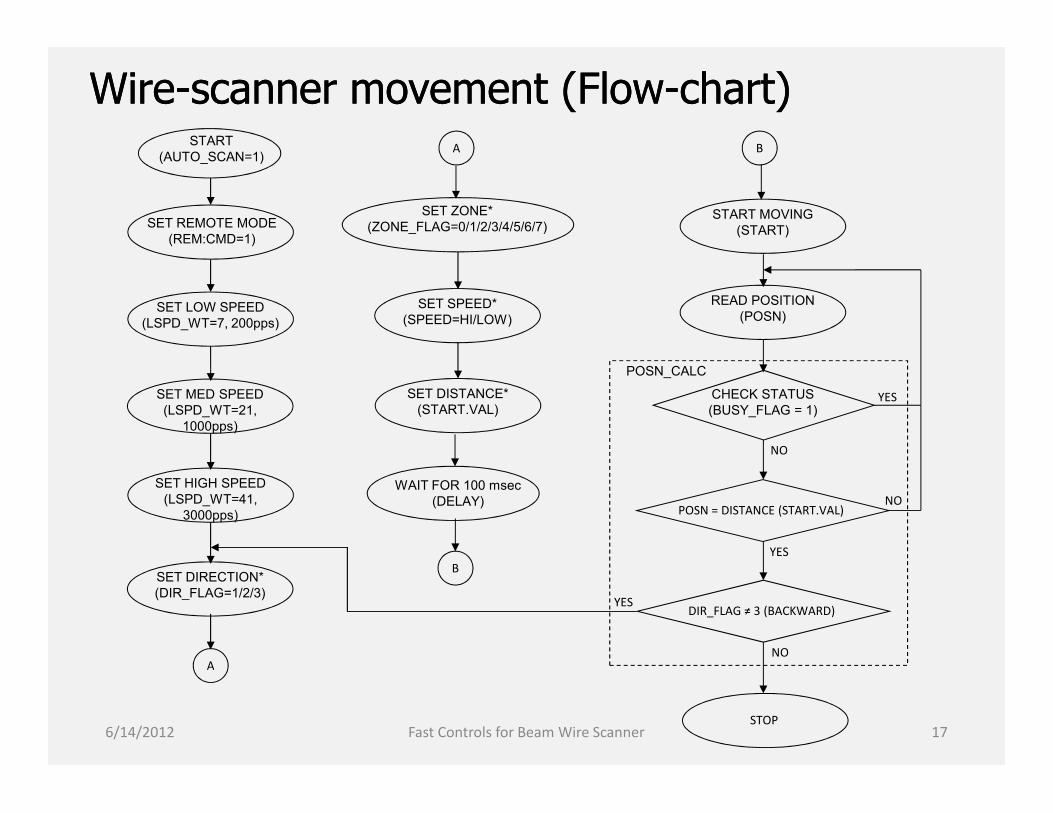
WireWire--scanner movement (Flowscanner movement (Flow--chart)chart)START
(AUTO_SCAN=1)
SET REMOTE MODE(REM:CMD=1)
SET LOW SPEED(LSPD_WT=7, 200pps)
SET MED SPEED(LSPD_WT=21,
1000pps)
START MOVING(START)
READ POSITION(POSN)
CHECK STATUS(BUSY_FLAG = 1)
POSN_CALC
A
YESSET DISTANCE*(START.VAL)
SET ZONE*(ZONE_FLAG=0/1/2/3/4/5/6/7)
SET SPEED*(SPEED=HI/LOW)
B
6/14/2012 17Fast Controls for Beam Wire Scanner
SET MED SPEED(LSPD_WT=21,
1000pps)
SET HIGH SPEED(LSPD_WT=41,
3000pps)
SET DIRECTION*(DIR_FLAG=1/2/3)
WAIT FOR 100 msec(DELAY)
STOP
CHECK STATUS(BUSY_FLAG = 1)
POSN = DISTANCE (START.VAL)
DIR_FLAG ≠ 3 (BACKWARD)
A
YES
YES
NO
NO
NO
SET DISTANCE*(START.VAL)
B

User interface (MEDM)User interface (MEDM) To control and monitor the data acquisition process, built using MEDM
Provisions provided for Defining peak positions and corresponding width around them
Specifying HIGH / MEDIUM / LOW speed index
Specifying EVR output, Pulse delay, pulse width, polarity etc. for particular BEAM mode
Selecting BEAM modes
6/14/2012 Fast Controls for Beam Wire Scanner 18

Test ResultsTest ResultsAs obtained, seems to be satisfactory!
6/14/2012 19Fast Controls for Beam Wire Scanner

Sincere Regards to:Sincere Regards to:
Kazuro FurukawaKazuro Furukawa
Tatsuro NakamuraTatsuro Nakamura
Naoko IidaNaoko Iida
Special Thanks to:Special Thanks to:
Tomohiro OkazakiTomohiro Okazaki
Shiro KusanoShiro Kusano
6/14/2012 20Fast Controls for Beam Wire Scanner
Sincere Regards to:Sincere Regards to:
Kazuro FurukawaKazuro Furukawa
Tatsuro NakamuraTatsuro Nakamura
Naoko IidaNaoko Iida
Special Thanks to:Special Thanks to:
Tomohiro OkazakiTomohiro Okazaki
Shiro KusanoShiro Kusano

Thank you!Thank you!Thank you!Thank you!
6/14/2012 21Fast Controls for Beam Wire Scanner