Development of Embedded EPICS and its Application to ...
100
1 Development of Embedded EPICS and its Application to Accelerator Control System Geyang Jiang DOCTOR OF PHYLOSOPHY Department of Accelerator Science School of Mathematical and Physical Science The Graduate University for Advanced Studies 2005
Transcript of Development of Embedded EPICS and its Application to ...

1
Development of Embedded EPICS and its Application to Accelerator Control System
Geyang Jiang
DOCTOR OF PHYLOSOPHY
Department of Accelerator Science
School of Mathematical and Physical Science
The Graduate University for Advanced Studies
2005

2
Development of Embedded EPICS and
its Application to Accelerator Control System
Geyang Jiang
No. 022203
Department of Accelerator Science
School of Mathematical and Physical Science
The Graduate University for Advanced Studies

3
Abstract
This thesis is on investigation and implementation of embedded EPICS controllers by the use of micro-ITRON to overcome many disadvantages caused by the advent of Ethernet-based device controllers.
At present almost all accelerator control systems are kind of DCS (Distributed Control Systems) on the basis of so called the standard model. In the standard model, the control system consists of three layers: the presentation layer, the device control layer and the interface layer.
Another trend of accelerator control systems at present is to use a free toolkit for its middle-ware. Among a few toolkits, EPICS (Experimental Physics and Industrial Control System) is the most widely used. EPICS was first developed in 1991. EPICS’s open, free and full DCS-based features have made it to be adopted in many control systems of scientific facilities, such as accelerators, telescopes, and large high-energy experiments.
EPICS is designed on the basis of the standard model. The first two layers, namely, the presentation layer and the device control layer, are divided functionally, but connected with each other through a high-speed network such as FDDI. The presentation layer which is called OPI (Operator Interface) layer in the EPICS terminology is typically composed of several workstations and X-terminals that are used as operator consoles. The device control layer consists of VME IOCs (Input/Output Controller) and/or other kinds of computers to accomplish the data processing and control logic. The interface layer is composed of I/O modules on IOC or other field bus modules that interface devices.
Recent rapid development of Ethernet has made it de fact international standard as the network in accelerator control systems. More and more device controllers with Ethernet interface have been widely used, such as PLCs (Programmable Logic Controller), to replace old field bus interface device controllers. These Ethernet-based device controllers are equipped with more CPU power and memory capacity, and have become intelligent enough to process the control logic that was originally accomplished by IOCs.
Now due to the advent of Ethernet-based device controllers, the standard EPICS 3-Layer model becomes redundant and show some disadvantages: l Lacking of real-time response: IOCs communicates with intelligent device
controllers through Ethernet, while, Ethernet, as defined in IEEE 802.3, is unsuitable for strict real-time industrial applications because its communication is non-deterministic.
l Ineffective use of hardware: in EPICS, when we use intelligent device controllers, a complicated device driver called “asynchronous driver” is put on IOCs to drive intelligent device controllers. Expensive VME machine are only used as “protocol transformer” that translates the manufacture’s proprietary protocol to EPICS CA (Channel Access) protocol.
4
l Duplication of programs: we have put runtime database on IOCs and also similar programs at intelligent device controllers such as Ladder on PLCs.
One way to avoid these disadvantages and maximally use the benefit of using intelligent device controllers is to implement integrating control software (IOC core program named as iocCore in EPICS) on these intelligent device controllers, thus making existed intelligent device controllers to work as separated IOCs. We call this type of controller embedded EPICS controller.
From EPICS base 3.14.x, iocCore supports can run not only on VxWorks but also recent versions of RTEMS, Solaris, Linux, HPUX, Darwin and Windows, and there have been some implementations of embedded EPICS controllers running on VxWorks and Linux. But they all have some shortages. For example, embedded EPICS controller running on Linux does not have any good real-time response, and embedded EPICS controller running on VxWorks lacks BSP (Board Support Package) support from the hardware manufacturer.
Many intelligent device controllers available on the market in Japan use micro-ITRON, a kind of Japanese domestic real-time kernel. The advantage of micro-ITRON is that these intelligent device controllers have BSP for micro-ITRON. We have investigated the use of micro-ITRON as a kernel on Ethernet-based device controllers and also implemented embedded EPICS Controllers on micro-ITRON.
After implementing embedded EPICS Controllers running on micro-ITRON, the redundant device control layer can be omitted. EPICS architecture can be recovered back to the standard 3-Layer model and the disadvantages mentioned before can be eliminated. Also running iocCore on micro-ITRON allows us to apply embedded EPICS concept to smaller devices that could not be supported by previous solution.
This thesis also discusses the performance of the embedded EPICS Controllers and shows that it can be used for real applications.
5
Contents
Abstract .....................................................................................................................3 1. Introduction............................................................................................................8 2. Establishment of "Standard Model" of accelerator control ....................................11
2.1. History and development of accelerator computer control system ...............11 2.1.1 Non-centralized computer adjuncts to the accelerator.........................11 2.1.2 CCS (Centralized Computer System) .................................................11 2.1.3 DCS (Distributed Computer System) .................................................12
2.2 Standard architecture of the accelerator computer control system.................14 3. Development and spread of EPICS.......................................................................15
3.1 EPICS .........................................................................................................15 3.1.1 EPICS architecture.............................................................................15 3.1.2 Basic characteristics...........................................................................16 3.1.3 CA (Channel Access) .........................................................................16 3.1.4 OPI ....................................................................................................17 3.1.5 IOC....................................................................................................17
3.2 OSI (Operation System Independence) layer in EPICS ................................18 4. Ethernet-based accelerator control systems...........................................................20
4.1 Rise of Ethernet-based controllers ...............................................................20 4.1.1 Commercial products .........................................................................20 4.1.2 Custom devices ..................................................................................22
4.2 Advantages of Ethernet as a field bus...........................................................24 4.2.1 Large-scaled facilities ........................................................................24 4.2.2 Small-scaled facilities ........................................................................25
4.3 Ethernet-based accelerator control systems (case studies) ............................25 4.3.1 J-PARC (JAERI/KEK) .......................................................................25 4.3.2 RIBF (RIKEN)...................................................................................27
4.4 Problems of "Protocol Converter" solution ..................................................28 4.4.1 IOCs as "Protocol Converters" ...........................................................29 4.4.2 Inefficient use of hardware resources .................................................29 4.4.3 Programming of inhomogeneous system............................................30 4.4.4 Synchronous /Asynchronous driver ....................................................31
4.4.4.1 Synchronous driver ................................................................................31 4.4.4.2 Asynchronous driver ..............................................................................32
4.4.5 Lack of real-time responsiveness........................................................34 5. A Solution based on "embedded EPICS" ..............................................................36

6
5.1 Embedded systems ......................................................................................36 5.2 RTOS ..........................................................................................................37 5.3 Embedded EPICS ........................................................................................39
5.3.1 Solution based on embedded EPICS approach....................................40 5.3.2 "Embedded EPICS" on VxWorks .......................................................40 5.3.3 "Embedded EPICS" on Linux ............................................................41 5.3.4 Disadvantages of existent “embedded EPICS” solutions ....................43
5.4 Micro-ITRON as a platform of "embedded EPICS" .....................................43 5.4.1 ITRON project and micro-ITRON .....................................................43 5.4.2 Applications in various fields .............................................................46 5.4.3 Controllers running micro-ITRON .....................................................47 5.4.4 Expectation of continuity in the feature ..............................................47
5.5 Consideration on technical feasibility ..........................................................48 5.5.1 Basic requirements to real-time kernel services ..................................48 5.5.2 Support for TCP/IP networking ..........................................................51 5.5.3 Availability of BSP.............................................................................53 5.5.4 Development environment .................................................................55
5.5.4.1 Cross-compiler tool chain ......................................................................56 5.5.4.2 Make utilities .........................................................................................58 5.5.4.3 PERL.....................................................................................................58 5.5.4.4 Debugger ...............................................................................................59 5.6 Freeware vs. commercial software ...............................................................61
6. Porting EPICS onto a micro-ITRON/SH4-based target.........................................63
6.1 Selection of hardware and software .............................................................64 6.1.1 Target device......................................................................................64 6.1.2 Micro-ITRON kernel .........................................................................65 6.1.3 Socket library.....................................................................................66 6.1.4 Cross-compiler tool chain ..................................................................67 6.1.5 Host platform for cross development..................................................68 6.1.6 ICE ....................................................................................................68
6.2 Building EPICS-base ...................................................................................70 6.2.1 Make system and GUI-based tool.......................................................70 6.2.2 Limited capabilities of C++ compiler for embedded systems..............71
6.2.2.1 Exception handling ................................................................................72 6.2.2.2 RTTI......................................................................................................74 6.3 Implementation of OSD libraries .................................................................75
6.3.1 OSD for multi-threading ....................................................................76 6.3.2 OSD for networking...........................................................................77 6.3.3 OSD for time functions ......................................................................78
6.4 Debugging and testing .................................................................................78 7. Performance evaluation of the EPICS on micro-ITRON.......................................80
7.1 Theory of the jitter test.................................................................................80
7
7.2 Hardware platform for the comparison.........................................................81 7.3 Detailed jitter test ........................................................................................82
7.3.1 Jitter on embedded Linux controller ...................................................82 7.3.2 Jitter on embedded micro-ITRON controller ......................................84 7.3.3 Jitter on embedded micro-ITRON controller with the modified time-difference calculation routine..............................................................85
7.4 Comparison of result ...................................................................................86 8. Conclusion and discussions ..................................................................................89 Acknowledgments....................................................................................................90 Bibliography ............................................................................................................91 Appendix I Functions supported in micro-ITRON3.0 specification kernel ..............93 Appendix II ITRON-specification kernel implementations ......................................94 Appendix III Function list in OSD library of micro-ITRON...................................96 Appendix IV Function list in Standard C library ..................................................100
8
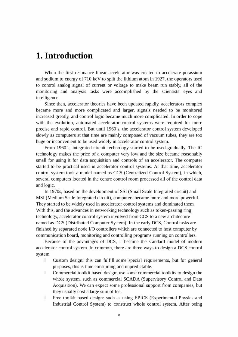
1. Introduction
When the first resonance linear accelerator was created to accelerate potassium and sodium to energy of 710 keV to split the lithium atom in 1927, the operators used to control analog signal of current or voltage to make beam run stably, all of the monitoring and analysis tasks were accomplished by the scientists' eyes and intelligence.
Since then, accelerator theories have been updated rapidly, accelerators complex became more and more complicated and larger, signals needed to be monitored increased greatly, and control logic became much more complicated. In order to cope with the evolution, automated accelerator control systems were required for more precise and rapid control. But until 1960’s, the accelerator control system developed slowly as computers at that time are mainly composed of vacuum tubes, they are too huge or inconvenient to be used widely in accelerator control system.
From 1960’s, integrated circuit technology started to be used gradually. The IC technology makes the price of a computer very low and the size became reasonably small for using it for data acquisition and controls of an accelerator. The computer started to be practical used in accelerator control systems. At that time, accelerator control system took a model named as CCS (Centralized Control System), in which, several computers located in the centre control room processed all of the control data and logic.
In 1970s, based on the development of SSI (Small Scale Integrated circuit) and MSI (Medium Scale Integrated circuit), computers became more and more powerful. They started to be widely used in accelerator control systems and dominated them. With this, and the advances in networking technology such as token-passing ring technology, accelerator control system involved from CCS to a new architecture named as DCS (Distributed Computer System). In the early DCS, Control tasks are finished by separated node I/O controllers which are connected to host computer by communication board, monitoring and controlling programs running on controllers.
Because of the advantages of DCS, it became the standard model of modern accelerator control system. In common, there are three ways to design a DCS control system: l Custom design: this can fulfill some special requirements, but for general
purposes, this is time consuming and unpredictable. l Commercial toolkit based design: use some commercial toolkits to design the
whole system, such as commercial SCADA (Supervisory Control and Data Acquisition). We can expect some professional support from companies, but they usually cost a large sum of fee.
l Free toolkit based design: such as using EPICS (Experimental Physics and Industrial Control System) to construct whole control system. After being
9
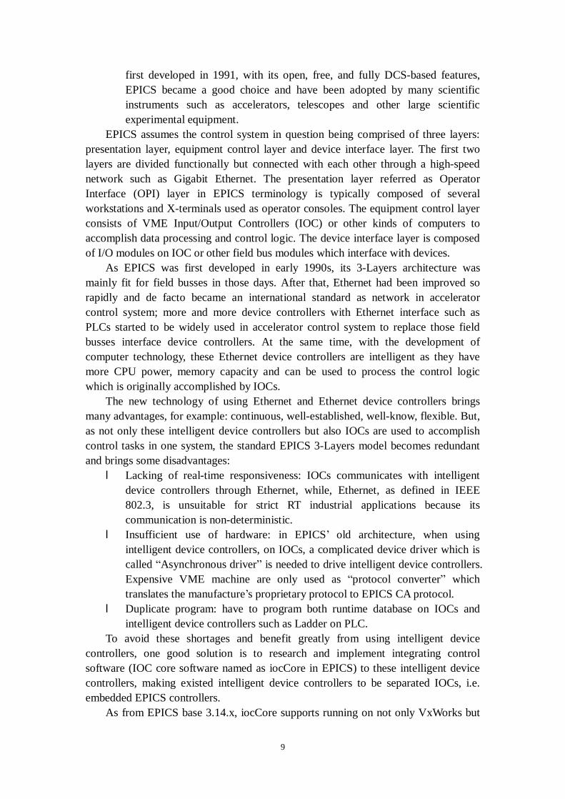
first developed in 1991, with its open, free, and fully DCS-based features, EPICS became a good choice and have been adopted by many scientific instruments such as accelerators, telescopes and other large scientific experimental equipment.
EPICS assumes the control system in question being comprised of three layers: presentation layer, equipment control layer and device interface layer. The first two layers are divided functionally but connected with each other through a high-speed network such as Gigabit Ethernet. The presentation layer referred as Operator Interface (OPI) layer in EPICS terminology is typically composed of several workstations and X-terminals used as operator consoles. The equipment control layer consists of VME Input/Output Controllers (IOC) or other kinds of computers to accomplish data processing and control logic. The device interface layer is composed of I/O modules on IOC or other field bus modules which interface with devices.
As EPICS was first developed in early 1990s, its 3-Layers architecture was mainly fit for field busses in those days. After that, Ethernet had been improved so rapidly and de facto became an international standard as network in accelerator control system; more and more device controllers with Ethernet interface such as PLCs started to be widely used in accelerator control system to replace those field busses interface device controllers. At the same time, with the development of computer technology, these Ethernet device controllers are intelligent as they have more CPU power, memory capacity and can be used to process the control logic which is originally accomplished by IOCs.
The new technology of using Ethernet and Ethernet device controllers brings many advantages, for example: continuous, well-established, well-know, flexible. But, as not only these intelligent device controllers but also IOCs are used to accomplish control tasks in one system, the standard EPICS 3-Layers model becomes redundant and brings some disadvantages: l Lacking of real-time responsiveness: IOCs communicates with intelligent
device controllers through Ethernet, while, Ethernet, as defined in IEEE 802.3, is unsuitable for strict RT industrial applications because its communication is non-deterministic.
l Insufficient use of hardware: in EPICS’ old architecture, when using intelligent device controllers, on IOCs, a complicated device driver which is called “Asynchronous driver” is needed to drive intelligent device controllers. Expensive VME machine are only used as “protocol converter” which translates the manufacture’s proprietary protocol to EPICS CA protocol.
l Duplicate program: have to program both runtime database on IOCs and intelligent device controllers such as Ladder on PLC.
To avoid these shortages and benefit greatly from using intelligent device controllers, one good solution is to research and implement integrating control software (IOC core software named as iocCore in EPICS) to these intelligent device controllers, making existed intelligent device controllers to be separated IOCs, i.e. embedded EPICS controllers.
As from EPICS base 3.14.x, iocCore supports running on not only VxWorks but

10
also recent versions of RTEMS, Solaris, Linux, HP-UX, Darwin and Windows, there have been some implementations of embedded EPICS controllers such as running on VxWorks and Linux. But they all have shortages. For example, embedded EPICS controller running on Linux is short of real-time responsiveness embedded EPICS controller running on VxWorks is lack of BSP support from the hardware manufacture.
Micro-ITRON is a small real-time kernel compared with RTEMS and VxWorks. It just has limited number of POSIX libraries. It is not a trivial problem if EPICS core software can be ported to the micro-ITRON platform in spite of the benefit of having EPICS running on micro-ITORN. The first target of this research is to port EPICS core software on the micro-ITRON platform. It also clarifies the range of portability of current EPICS core software and will contribute to the future improvement of EPICS software. In the second stage of the research, we tested the real-time performance of EPICS on micro-ITORN. The result shows better real-time performance of EPICS on micro-ITRON over the other embedded EPICS solution. It means the EPICS on micro-ITRON is applicable to the actual accelerator controls where the real-time response can be critical. In other words, this research opens a wide possibility of application of embedded EPICS to the control system. We can also apply the concept of embedded EPICS controller on micro-ITRON to the existing control system, which already include intelligent controllers running micro-ITRON and will add various benefit to the system, performance, maintainability, and the simplicity of the system.

11
2. Establishment of "Standard Model" of
accelerator control
2.1. History and development of accelerator computer
control system
2.1.1 Non-centralized computer adjuncts to the accelerator
In the beginning, particle accelerators were built without computer control systems. As small computers became affordable, accelerator institutions began to experiment with the new possibilities that computers afforded. The first era is non-centralized computer adjuncts to the accelerator. The early control system of AGS (Alternating Gradient Synchrotron) mirrors this experience. First attempts to connect computers to the AGS began in 1966, with the introduction of a PDP-8 in the control room. The initial goal was to monitor instrumentation signals in real time, using ADC cards mounted in the computer bus; programming was in assembler using paper tape, output was on a Teletype. A disk and tape were added, and in 1968, a second PDP-8. By June 1968, a steering magnet was under computer control, to minimize beam spill fluctuations in a slow extracted beam. In July, an alphanumeric CRT display was added.
2.1.2 CCS (Centralized Computer System)
The second generation of the accelerator computer control system had started to be implemented according to the developed computer technologies based on the CCS architecture. One/several computers located in the central control room deal with all the control process and accomplish all of the basic functions in the control system.
The prototype of second generation of AGS control system [1] started from 1971 is a typical one based on CCS. Its architecture is shown in Figure 2.1:

12
In that, the mainframe computer is PDP-10, a custom hierarchical network was
developed to permit PDP-8s managing Datacon-II field buses in real time, while reporting their results to application programs that ran in time-sharing mode on the mainframe. A high-speed link (1 Mbit/sec) was developed between the PDP-10 and PDP-8s using custom I/O cards. A custom monitor was developed for PDP-8s, an early RTOS (Real Time Operating System). Applications were programmed on the PDP-10 in the FORTRAN language. Two fast alphanumeric video displays were provided at each of three operator's consoles using commercial display generators (and custom I/O cards and driver). Operator input was provided by a custom panel with knobs, buttons, and a trackball (a custom PDP-10 I/O card and driver). Tektronix terminals provided for graphics displays. The system eventually provided for 20 field buses, 4 per PDP-8, with 256ddresses per bus. A variety of hardware devices was developed for the field buses.
2.1.3 DCS (Distributed Computer System)
With the extension of control system scale and growth of data processing, CCS can’t fulfill all the control tasks anymore. Furthermore, as all control procedures are carried out on the central computer, there are potential dangers in this way: l Once the collapse of central computer will make the whole system paralysis.
In other words, the central computer is a single point of failure. l With the extension of accelerator system’s scale, the position of equipment
which to be controlled are scaled too. Gathering large scale and complicated data into central computer is not only inconvenient but also ineffective.
The appearance of DCS, give us a good solution to CCS’ shortages. It has become the standard of modern accelerator control system model. For example, in the current control system of KEKB [2], the scheme of DCS was taken. Figure 2.2 shows its structure:
Central computer(PDP10)
Operatorinput Disk Printer
High speed link
I/O controller(PDP-8s) ............ I/O controller
(PDP-8s)I/O controller
(PDP-8s)Field busses
DevicesDevices Devices...... ......Figure 2.1 Early control system of AGS based on CCS
13
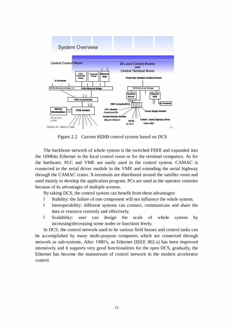
The backbone network of whole system is the switched FDDI and expanded into
the 10Mbits Ethernet in the local control room or for the terminal computers. As for the hardware, PLC and VME are easily used in the control system. CAMAC is connected to the serial driver module in the VME and extending the serial highway through the CAMAC crates. X-terminals are distributed around the satellite room and used mainly to develop the application program. PCs are used as the operator consoles because of its advantages of multiple screens.
By taking DCS, the control system can benefit from these advantages: l Stability: the failure of one component will not influence the whole system. l Interoperability: different systems can connect, communicate and share the
data or resource correctly and effectively. l Scalability: user can design the scale of whole system by
increasing/decreasing some nodes or functions freely. In DCS, the control network used to be various field busses and control tasks can
be accomplished by many multi-purpose computers which are connected through network as sub-systems. After 1980’s, as Ethernet (IEEE 802.x) has been improved intensively and it supports very good functionalities for the open DCS, gradually, the Ethernet has become the mainstream of control network in the modern accelerator control.
Figure 2.2 Current KEKB control system based on DCS

14
2.2 Standard architecture of the accelerator computer
control system
The standard architecture of the accelerator control system based on DCS [3] can be shown as Figure 2.3:
The whole system is separated to presentation layer, equipment control layer, and
the device interface layer. At the presentation layer, workstations are used to make and run application programs for operations. This layer also includes high-speed reliable network. The Input/Output controllers, which located at the equipment control layer, are connected to equipments through various field busses which belong to device interface layer.
Profit from the characteristics of open, distributed, easy to be upgraded and flexible, the accelerator control system based on this standard architecture has become the mainstream in large experimental physics control systems. There are two schemes for designing accelerator control system of standard model. One is to develop nearly all of the software by themselves, for example, SRRC (Synchrotron Radiation Research Center) in Hsinchu, Taiwan. The other is to make use of professional toolkits, for example, business software SCADA [4] or the professional accelerator control software EPICS (Experimental Physics and Industrial Control System).
Presentation layer
Equipment
Device interface layer
Equipment control layer
Figure 2.3 Standard model of DCS
15
3. Development and spread of EPICS
In this chapter, we will briefly review EPICS software tool. Some of important concept in EPICS such as CA protocol, IOC and its runtime database and so on will be introduced in the following sections.
3.1 EPICS
EPICS is primarily the work of the accelerator technology group (AT-8) at Los Alamos National Lab and the Advanced Photon Source (APS) at Argonne National Lab. The EPICS involves three aspects: l Architecture for building scalable control systems. l A collection of code and documentation comprising a software toolkit. l A collaboration of major scientific laboratories and industry. Now more than 70 laboratory, university, and industrial facilities throughout
North America, Europe, and Asia use EPICS. These sites include physics accelerators and detectors, telescopes, and various industrial processes. Up till now, these members of collaboration have contributed many products, documents and source code to EPICS. User of EPICS can use these resources without any charge.
3.1.1 EPICS architecture
The architecture of EPICS embodies the “standard model” of DCS design. The main basic feature of EPICS is that it is fully distributed. It requires no central device or software entity at any layer. This achieves the goals of easy scalability, of robustness (no single point of failure) and of incremental operation and upgrade. Thus it is not unusual for parts of a total EPICS system to be in production, while other parts are in development, and yet other parts are shutdown. EPICS is comprised of three physical layers [5]. l Input/Output Controller (IOC). This physical front-end layer is typically built
from VME/VXI hardware crates, CPU boards, and I/O boards. The I/O boards drive the hardware plant directly or through a variety of standard field buses such as GPIB, Bitbus, CANbus, RS-232/485, Ethernet, and some PLC vendor protocols. The VME CPU boards are often from the Motorola 680X0 and PowerPC families (with some Intel) and run the VxWorks real-time kernel.
l Operation Interface (OPI). This physical back-end layer is implemented on popular workstations such as Sun, HP, UNIX, or Windows NT/Linux on PC hardware.
16
l Local Area Network. IOCs and OPIs are connected by the network layer, which is any combination of media (Ethernet, FDDI, ATM, etc.) and repeaters and bridges supporting the TCP/IP Internet protocol and some form of broadcast or multicast.
3.1.2 Basic characteristics
The basic attributes of EPICS are [6]: l Tool Based: EPICS provides a number of tools for creating a control system.
This minimizes the need for custom coding and helps ensure uniform operator interfaces.
l Distributed: An arbitrary number of IOCs and OPIs can be supported. As long as the network is not saturated, no single bottle neck is present. A distributed system scales nicely. If a single IOC becomes saturated, its functions can be spread over several IOCs. Rather than running all applications on a single host, the applications can be spread over many OPIs.
l Event Driven: The EPICS software components are all designed to be event driven to the maximum extent possible. For example, rather than having to poll IOCs for changes, a CA client can request that it be notified when a change occurs. This design leads to efficient use of resources, as well as, quick response times.
l High Performance: A SPARC based workstation can handle several thousand screen updates a second with each update resulting from a CA event. A 68040 IOC can process more than 6,000 records per second, including generation of CA events.
3.1.3 CA (Channel Access)
In EPICS, there is a software layer named as CA which connects all clients with all servers [7]. It’s the backbone of EPICS and hides all the details of the TCP/IP network from both clients and servers. CA also creates a very solid firewall of independence between all client and server code, so they can run on different processors, and even be from different versions of EPICS. CA mediates different data representations, so clients and servers can mix ASCII, integral, and floating (as well as big- endian and little-endian) types where each uses its natural form.
The design of CA provides very high performance of allowing throughput rates on the order of 10,000 “gets” or “puts” per second under heavy load, yet minimizing latency to about 2 milliseconds under light load. If the medium allows it, many clients and servers can simultaneously sustain these rates. Since EPICS is a fully-connected and flat architecture, every client and every server make connections with no ‘relay’ entities, so there are no bottlenecks beyond the physical limits of the medium. CA also uses a technique called ‘notify by exception’ or callback (also called “publish and subscribe”). Once a client has expressed an interest in certain data to a server, the
17
server notifies the client only when the data changes. This not only minimizes traffic, but signals both the health of the server and the freshness of the data.
With CA protocol, all data carry time-stamps, validation information based on both the quality of connection, and validity down to the hardware layer as explained later. Thus, a critical client implementing a global feedback loop can assure it is operating only with fully validated data.
3.1.4 OPI
The OPI takes the role of a client in the client-server architecture. It usually runs on a workstation/PC and represents the various top software application. Typical generic OPI has operator control screens, alarm panels, and data archive/retrieval tools. The operator screens provide mimic diagrams (sometimes called synoptic displays), tabular data, and simulated meters, buttons, and sliders. These are all configured with simple text files or point-and-click drawing editors. Another very useful software is the Knob Manager. It allows traditional tuning by operators through a standard OPI. More generic software such as the Display Manager, the Alarm Handler, the StripChart, the TCL/Tk graphical scripting language, and a channel data archiver can also be run on OPIs. Using client-server model, OPIs are very high in performance. For example, operator screens with 1000 objects are brought up in less than one second and can update dynamically about 5000 objects/sec. The alarm panel can react to 1000 changing alarm conditions/sec. The archiver can sustain 5000 transactions/sec to disk. All of these levels are achievable on the lowest cost workstations.
3.1.5 IOC
The IOC takes the role of a server in the paradigm client-server architecture. An IOC contains the following software components: supplied by EPICS.
l IOC Database: The memory resident database plus associated data structures. l Database Access: With the exception of record and device support, all access
to the database is via the database access routines. l Scanners: The mechanism for deciding when records should be processed. l Record Support: Each record type has an associated set of record support
routines. l Device Support: Each record type can have one or more sets of device
support routines l Device Drivers: Device drivers access external devices. A driver may have an
associated driver interrupt routine. l CA: The interface between the external world and the IOC. It provides a
network independent interface to database access. l Monitors: Database monitors are invoked when database field values change.
18
l Sequencer: A finite state machine. The IOC's fundamental responsibility is to input data from the “process",
manipulate it in a predefined manner, and output data to control the `process'. These inputs, data manipulation, and outputs are defined by the application developer by configuring records that become part of the IOC's database. The IOC's primary task is to `scan' the database, deciding when to and knowing how to execute predefined records. Records can be linked together to create control algorithms and sequences.
The IOC software is designed so that the database access layer knows nothing about the record support layer other than how to call it. The record support layer in turn knows nothing about its device support layer other than how to call it. Similarly the only thing a device support layer knows about its associated driver is how to call it. This design allows a particular installation and even a particular IOC within an installation to choose a unique set of record types, device types, and drivers. The remainder of the IOC system software is unaffected.
3.2 OSI (Operation System Independence) layer in
EPICS
In the beginning, IOC is typically built from VME/VXI machine that runs the VxWorks as RTOS on it. IocCore can only run on VxWorks before the EPICS base version 3.14. Even before EPICS 3.14, there were preliminary works to port EPICS to the RTOS other than VxWorks. There are several reasons for such trial such as the expensive license fee of VxWorks, user’s flavor of other RTOS and so on. For example, in North American, a number of projects prefer to use RTEMS as the target real time operating system for their EPICS IOCs. It has been shown that RTEMS provides a real time behavior that is comparable to VxWorks, which makes it an interesting and promising low-cost alternative to VxWorks. Also in Japan, A porting of iocCore on LynxOS was carried out in Linac control system of KEKB in 1994. But this porting is much difficult and different comparing with the current situation as iocCore was bundled tightly with VxWorks library.
On the other hand, to improve the virtual abstraction and add complex functionality to large, complex applications, one approach of modern software design is to build a system in layers [8]. For example, hardware abstract layer is often used as a layer that sits above the operating system, to hide details of under layer and provide top layer a unified component integration and management scheme. This layer-based design is also used in EPICS to satisfy the increased requirements of running IOC core software onto different RTOS and hardware we discussed above.
Since EPICS base 3.14, an Operating System Independent (OSI) layer was added into iocCore which is similar as the abstract layer, completely encapsulating operating system dependent functions and resources, such as semaphores, threads, sockets, timers, and a symbol table containing function and variable names [9]. All

19
hardware-specific support was unbundled and is now being built as separate modules. The EPICS build system was restructured to decouple operating system, architecture, and compiler specifics: the IOC components are now built targeting any supported OS, architecture and compiler permutation. So the iocCore can run on recent versions of VxWorks, RTEMS, Solaris, Linux, HP-UX, Darwin and Windows today.
With the introduction of OSI, there are many advantages: l Flexibility: fast changing work-processes and workflows need flexible access
to functions and data. High barriers between systems are falling or changing to small boundaries as modularity is growing. Good system integration architecture and the appropriate middleware help to provide this flexibility.
l Speedy development: where functions and data have to be used across different systems, OSI speeds development and changes (in the long term, though not necessarily in the short term).
l Cost: the costs of building and maintaining unique one-to-one integrations between systems are rapidly growing for larger systems. Changes are expensive, as they need to be applied to more than just the primary system. With OPI layer, changing low level RTOS will not affect upper layer.
l Standardization: as methods and interfaces are re-used, fewer components and skills are needed. Having a way of handling integration makes it easier to decide what you don’t need to do.
l Data integrity, reliability and robustness: as more and more data are used across systems and different work processes, system integration architecture and this OPI abstract layer solution ensures the integrity of the data across systems and situations of use.
l New products and services: easy access to new delivery platforms. l Prevent lock-in by vendors: users can replace a sub-system from vendor A by
an equivalent system from vendor B, without having to reconfigure the rest of the system.
l System planning: standardization allows technical planning departments to use tools that will make the planning-process much easier. The focus will no longer be fixed on specific technical problems about lower RTOS but much more on workflows, or rather on optimizing the workflows.
l Training: an understanding of the workflows in which the operators are involved will become more necessary in the future than today. Therefore it will be necessary, not only for dedicated technical training for separated RTOS, but mainly for education on understanding the whole EPICS toolkit. This can be much simpler if the system architecture is based on generic and pre-defined processes rather than on proprietary structures. Time and cost in training can be reduced and the trained staff can be deployed very flexibly.

20
4. Ethernet-based accelerator control
systems
In recent 25 years, Ethernet has been developed greatly and become more and more popular not only in office or home but also in industrial field. Wide acceptance of Ethernet as foundation of networking accelerates the advancement of the technology. It also widens the field of application of Ethernet based technology. Use of Ethernet as a field bus is one of these applications.
At first, the IEEE 802.3 standard is for a CSMA/CD LAN. Ethernet is a specific product that almost implements this standard (Ethernet differs from the standard in one header field). The IEEE 802.3 standard has a history like this:
In 1973, Xerox Corporation’s Palo Alto Research Center began the development of a bus topology LAN.
In 1976, carrier sensing was added, and Xerox built a 2.94 Mbps CSMA/CD system to connect over 100 personal workstations on a 1 km cable. Xerox Ethernet was so successful.
In 1980 Digital Equipment Corporation, Intel Corporation and Xerox had released a de facto standard for a 10 Mbps Ethernet, informally called DIX Ethernet (for the initials of the 3 companies). This standard was a basis for the IEEE 802.3.
In 1983 IEEE 802.3 10Base5 was approved. In 1986, 10Base2 was approved. In 1991, 10BaseT was approved. In 1994-1995, 10BaseF was approved. In 1995 100 Mbps Ethernet was released. In 1998-1999, Gigabit Ethernet was approved.
4.1 Rise of Ethernet-based controllers
As the Ethernet gradually become the international standards, more and more manufactures start to support the device controllers with Ethernet interface. Ethernet is so popular that most of those field busses products have the Ethernet modules to interface betweens field busses and Ethernet. Also, Ethernet has become the best choice of local network in EPICS.
4.1.1 Commercial products
The most popular Ethernet device controller is PLC, which is intensively used in industrial fields. Today, over hundreds of brands of PLCs are available on the markets,
21
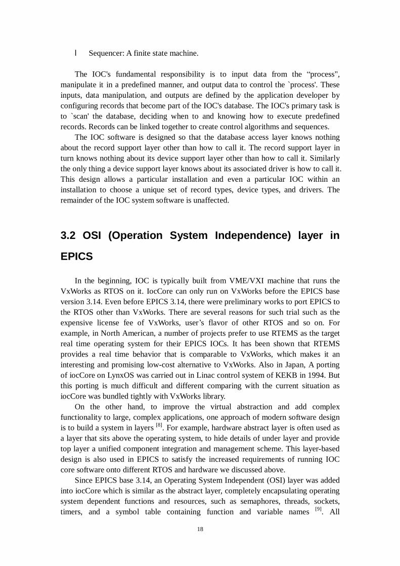
which include various CPU and I/O modules. Users can make free choice to customize their system. The main brands of PLCs on Japan market are Omron, Yokogawa, and Mitsubishi. Figure 4.1 shows one kind of PLC made by Mitsubishi, its model is FA-M3.
The latest large accelerator projects have avoided the need for home-built solutions
for accelerator control and have chosen EPICS. However, for many reasons it is often required to integrate non-EPICS, particularly PLC, systems into the control system. For these systems EPICS can be seen as a SCADA package.
These main points urge PLCs are used in EPICS: l Subsystems may come with PLC controls When subsystems are delivered with
a PLC control system, there are a number of reasons not to change: l There may not be time to re-implement the subsystem controls cleanly before
the system is needed. l There is not sufficient knowledge of how the subsystem operates or the controls
requirements. l The system vendor will not guarantee the whole system if the controls are
changed. l Policy decisions. For examples, there may be a desire by the equipment group
responsible for a sub-system, or lab management, to use industrial controls. This may simply be because they have always done it that way; Copy of an existing system; Knowledge within the equipment group; Lack of knowledge about EPICS Technical advantages of a PLC It may be that the system has to be safety certified, and that the PLC components are themselves certified for use in a safety system.
Another commercial product is Yokogawa WE7000, a module-type measurement
station [10]. Figure 4.2 shows WE7000. It has three modules: a 100 MS/s oscilloscope (WE7111), a 100 kS/s digitizer (WE7271), and a 10MHz function generator
Figure 4.1 FA-M3 PLC (made by Yokogaw)

22
(WE7121). The oscilloscope/digitizer modules of WE7000 can be used as low-cost Ethernet-based waveform monitors.
Table 4.1 lists the commercial products used in Japanese accelerator control system now:
Table 4.1 Commercial products used in Japan
Device Type Maker Protocol FA-M3 PLC Yogogawa TCP/UDP
MELSEC-Q PLC Mitsubishi TCP/UDP CV-1/CH-1 PLC Omron TCP/UDP
WE7000 Oscilloscope Yokogawa TCP/UDP MCU General Purpose NDS TCP/UDP
4.1.2 Custom devices
Besides those commercial ones, several kinds of custom device controllers are developed for special purpose usage in accelerators:
The first one is EMB-LAN100 which was developed by KEK for the control of power supplies of DTL Q-magnets. It was shown in Figure 4.3:
Figure 4.2 WE7000 (made by Yokogawa)

23
Table 4.2 lists the details of EMB-LAN100:
Table 4.2 Specification of EMB-LAN100 CPU SH3 (HITACHI), 133Hz memory 8MB (S-RAM), 1MB (EP-ROM) OS NORTi V4 protocol TCP/IP, UDP/IP port 10/100Base-T, RS-232C power supply 5V/1.2A size 160(W) x 100(D) (PCB Size) I/O Digital 16 Bit
The second one is N-DIM (Ethernet-based Device Interface Modules) which was
developed by RIKEN for general purpose of control and monitoring [11]. It was shown in Figure 4.4:
Figure 4.3 EMB-LAN100 (developed by KEK)
Figure 4.4 N-DIM (developed by RIKEN)
24
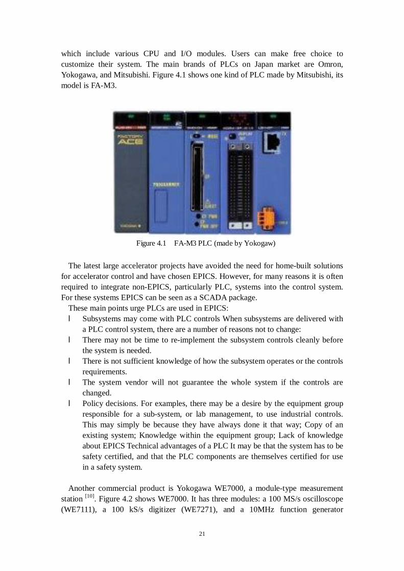
The important features of N-DIM are listed in Table 4.3:
Table 4.3 Specification of N-DIM CPU SH4 (HITACHI) memory 6MB (S-RAM), 1MB (EP-ROM) OS Micro ITRON 2.0 protocol TCP/IP, UDP/IP service FTP, Telnet port 10/100Base-T, RS-232C power supply 5V/1.5A, 24V/1A (for I/O) size 320(W) x 210(D) x 30(H)
DI : 32 (Isolated) DO : 32 (Isolated) AI : 16
I/O
another DI : 8 (Isolated)
N-DIM is a radiation-resistance device and each one has an IP address. When it is used to control a beam equipment such as a beam profile monitor, it plays roles both a server and a client in the control system. Control commands are written in ASCII code. Table 4.4 summarizes all the custom Ethernet-based controllers used in Japanese accelerator controls at present:
Table 4.4 Custom devices used in Japan
Device Type Maker Protocol EMB-LAN100 DIM Custom TCP/UDP
N-DIM DIM Custom TCP/UDP
4.2 Advantages of Ethernet as a field bus
Using Ethernet as a kind of field bus has the following benefits: l Continuity – we can expect continuity in the future because TCP/IP is a
widely used standard in various fields l Well-established – TCP/IP is a well-established technology l Well-known – Ethernet and TCP/IP are popular and the knowledge of their
protocols is widespread l Flexible – Ethernet can be extended easily and devices can also be added
onto it easily
4.2.1 Large-scaled facilities
Besides those backgrounds and pre-limitations we have to choose Ethernet-based

25
device controllers, the advantages are obvious. Accelerator is usually a long term scientific complex, from the commission it will persist a long time such as tens of years. We always expect we can get the supports from manufactures for the whole life of the device controllers working.
As Ethernet is based on TCP/IP, it’s an international standard and widely supported by nearly all of the manufactures. After so many years’ research and development, TCP/IP itself also becomes a complicated and reliable protocol to guarantee the stable network communications. It’s hard to image in several ten years, we will loose the technical supports of the Ethernet products.
4.2.2 Small-scaled facilities
In accelerator, as to focus on and trace the new idea of physical theory, sometimes small-scaled test facilities are needed to be assembled in short time. Since Ethernet is easy to constructed and disassembled, comparing with field busses ones, Play & Play characteristic make Ethernet-based device controllers are easy to be used.
Especially, PLCs were original developed to provide a replacement for large relay based control panels. These systems were inflexible requiring major rewiring or replacement whenever the control sequence was to be changed. The development of the micro processor from the mid 1970's have allowed PLCs to take on more complex tasks and larger functions as the speed of the processor increased. For temporary use, they can fully replace those VME machines in old days.
4.3 Ethernet-based accelerator control systems (case
studies)
From the beginning, Ethernet-based device controllers are only used in some parts of accelerator control system especially to control a sub system such as PPS (Personal Protection System), but with its advantages, some newly constructed are considering taking the scheme of only using Ethernet-based device controllers in the whole system.
4.3.1 J-PARC (JAERI/KEK)
J-PARC is a high-intensity (1MW of beam power) proton accelerator being constructed jointly by Japan Atomic Energy Research Institute (JAERI) and High Energy Accelerator Research Organization (KEK) in JAERI Tokai site. It consists of a 400-MeV Linac, a 3-GeV Rapid Cycling Synchrotron (RCS) and a 50-GeV Main Ring synchrotron (MR). The first beam commissioning of Linac and RCS is scheduled in 2006 and MR in 2007. In parallel with it, a part of 60-MeV Drift-Tube Linac (DTL) of the J-PARC accelerator complex is now being constructed at KEK

26
site for R&D purposes [12]. It has been decided to use EPICS as the control system environment, mainly
because it is widely used in this field of accelerator controls and its accumulated software is fully utilizable. One of the special features of the whole system is maximal use of network technology. Ethernet-based controllers such as PLCs and measurement instruments are going to be used instead of other field busses such as General Purpose Interface Bus (GPIB) or CAMAC serial highway. The network hardware and software can be easily standardized.
The J-PARC control system is designed following so-called standard model architecture based on EPICS. The system consists of three layers, e.g. presentation layer, equipment control layer, and device interface layer as shown in following Figure 4.5:
At the presentation layer, server workstations will be used to make and run application programs for operations. This layer includes high-speed reliable network. The network is based on switched Gigabit Ethernet (GbE) operated in duplex mode.
At the device interface layer, it was decided to use TCP/IP protocol on the 10/100 Mbps Ethernet as the common field bus. Common device driver for network devices and device support routines have been developed for various network devices. There will be a very large number of Ethernet-based device controllers used in order to reduce cost and get flexibilities in 10msec ranges. In which, PLCs and DIMs will be used in the control systems, where EMB-LAN100 is an interface module for DTL Q magnet power supplies and BPMC is for MR BPMs (Beam Position Monitors). VME bus modules will be used in order to obtain fast data acquisition and/or quick responses in 10 micro-second to milli-second range.
The main part of the J-PARC accelerator control network constructed using Gigabit Ethernet technology with fiber-optic cables. There are 17 local node stations in the network. All local node switches are connected to the central core switches in the star
Figure 4.5 The standard model ofJPARC control system

27
topology. At the central node, there are two core switches connected with each other for fail-over switching capability. At each local node, there are edge-switches connected with each other for the fail-over capability similar to the central node. For each connection between the central node and a local node, there are at least two paths provided for redundancy as shown in following Figure 4.6:
In JARPC, Ethernet, Ethernet-based device controllers with EPICS are selected
intensively for stability of the TCP/UDP standard protocol widely used in commercial fields and flexibility in a configuration of the devices.
4.3.2 RIBF (RIKEN)
RIBF (RIKEN radioisotope Beam Factory) control system is the extension of completed control system RARF (RIKEN Accelerator Research Facility). This is one typical example of upgrade based on those old ones. The main reason of replacing old field busses device controllers with Ethernet is the some special field busses products’ life-time is short, which we mentioned before.
The RARF has an accelerator complex consisting of the RIKEN Ring cyclotron (RRC) as a main accelerator and its two different types of injectors, frequency-variable RIKEN heavy-ion linac (RILAC) and AVF Cyclotron (AVF). The facility provides heavy ion beams over the whole atomic mass range and in a wide energy range from 0.6 MeV/nucleon to 135 MeV/nucleon. One of the remarkable features of this facility is capability of supplying light-atomic-mass radioisotope beams with the world-highest level of intensity. To boost the RRC beam’s output
Figure 4.6 Schematic view of thenetwork configuration
28
energy up to 400 MeV/nucleon for light ions and 350 MeV/nucleon for very heavy ions such as uranium, the RIBF project is now under construction. Having the RRC as an injector, a new cyclotron cascade consisting of three ring cyclotrons will be commissioned in 2005 [13].
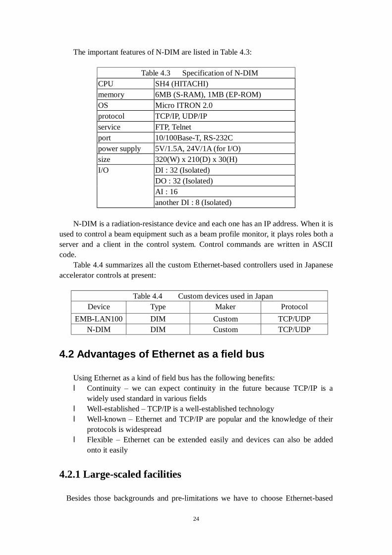
The system expansion of RARF has always been required for the RIBF. New components have been introduced into the cases such as the upgrade project of RILAC, renewals of very old components and so on. There is a demand that the system expansion should be carried out only by adding the parameters of new components into the EPICS database, if they are controlled by either the CAMAC or the GP-IB. On the other hand, in investigation of a control system of the RIBF, it may be the easiest solution to expand the current system to the next one because the RIBF is a cyclotron facility as well as the RARF. However, both the interfaces have already become old and it is not a good idea to employ such old ones for the control of new components. Then it was decided to introduce three types of new control interfaces into the EPICS control system. The first one is NIO interface, which is used for new magnet power supplies. All magnet power supplies in RIBF will be controlled by NIO. In the RARF, we have already controlled the power supplies with NIO in the extended beam line of RILAC in the EPICS control system by making the device support for it. The second one is PLC, which is used for a new RF system and so on. The third one is N-DIM, which is our original control device developed to substitute for the CAMAC-CIM/DIM system. In the RIBF control system, N-DIM is used for a various purpose; to control all beam diagnostic equipment, all vacuum systems, driving system for deflectors and so on. Furthermore, it is also planned to replace the CAMAC-CIM/DIM in the RARF with N-DIM gradually. Figure 4.7 shows the relation between an interface device and a component of RARF and RIBF:
Figure 4.7 Interface devices in RARF/RIBF
4.4 Problems of "Protocol Converter" solution
When EPICS’ Standard Model was initially designed, the architecture is very clear. As mentioned in J-PARC control system, the system consists of three layers, e.g. presentation layer, equipment control layer, and device interface layer. IOCs which
29
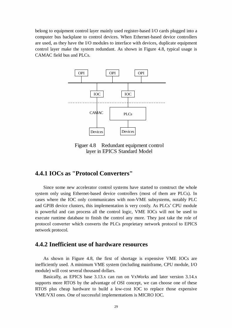
belong to equipment control layer mainly used register-based I/O cards plugged into a computer bus backplane to control devices. When Ethernet-based device controllers are used, as they have the I/O modules to interface with devices, duplicate equipment control layer make the system redundant. As shown in Figure 4.8, typical usage is CAMAC field bus and PLCs.
4.4.1 IOCs as "Protocol Converters"
Since some new accelerator control systems have started to construct the whole system only using Ethernet-based device controllers (most of them are PLCs). In cases where the IOC only communicates with non-VME subsystems, notably PLC and GPIB device clusters, this implementation is very costly. As PLCs’ CPU module is powerful and can process all the control logic, VME IOCs will not be used to execute runtime database to finish the control any more. They just take the role of protocol converter which converts the PLCs proprietary network protocol to EPICS network protocol.
4.4.2 Inefficient use of hardware resources
As shown in Figure 4.8, the first of shortage is expensive VME IOCs are inefficiently used. A minimum VME system (including mainframe, CPU module, I/O module) will cost several thousand dollars.
Basically, as EPICS base 3.13.x can run on VxWorks and later version 3.14.x supports more RTOS by the advantage of OSI concept, we can choose one of these RTOS plus cheap hardware to build a low-cost IOC to replace those expensive VME/VXI ones. One of successful implementations is MICRO IOC.
OPI OPI OPI
IOC IOC
Figuer 4.8 Redundant equipment controllayer in EPICS Standard Model
Devices
PLCs
Devices
CAMAC
30
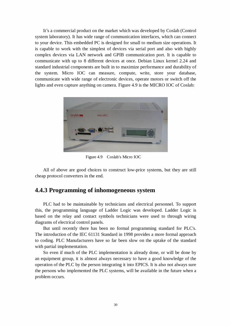
It’s a commercial product on the market which was developed by Coslab (Control system laboratory). It has wide range of communication interfaces, which can connect to your device. This embedded PC is designed for small to medium size operations. It is capable to work with the simplest of devices via serial port and also with highly complex devices via LAN network and GPIB communication port. It is capable to communicate with up to 8 different devices at once. Debian Linux kernel 2.24 and standard industrial components are built in to maximize performance and durability of the system. Micro IOC can measure, compute, write, store your database, communicate with wide range of electronic devices, operate motors or switch off the lights and even capture anything on camera. Figure 4.9 is the MICRO IOC of Coslab:
All of above are good choices to construct low-price systems, but they are still
cheap protocol converters in the end.
4.4.3 Programming of inhomogeneous system
PLC had to be maintainable by technicians and electrical personnel. To support this, the programming language of Ladder Logic was developed. Ladder Logic is based on the relay and contact symbols technicians were used to through wiring diagrams of electrical control panels.
But until recently there has been no formal programming standard for PLC's. The introduction of the IEC 61131 Standard in 1998 provides a more formal approach to coding. PLC Manufacturers have so far been slow on the uptake of the standard with partial implementation.
So even if much of the PLC implementation is already done, or will be done by an equipment group, it is almost always necessary to have a good knowledge of the operation of the PLC by the person integrating it into EPICS. It is also not always sure the persons who implemented the PLC systems, will be available in the future when a problem occurs.
Figure 4.9 Coslab's Micro IOC
31
4.4.4 Synchronous /Asynchronous driver
In EPICS, a driver for hardware called “Device Support” is needed to drive new hardware introduced into a system [14, 15]. A device support itself is a collection of functions that are programmed to make a hardware device perform some I/O-related activities, and may contain an initialization function, a read function, a write function, etc. A device support routine has knowledge of the record definition. It also knows how to talk to the hardware directly or how to call a device driver which interfaces to the hardware. Thus device support routines are the interface between hardware specific fields in a database record and device drivers or the hardware itself. The purpose of device support is to hide hardware specific details from record processing routines.
Device support modules can be divided into two basic classes: synchronous and asynchronous. Synchronous device support is used for hardware that can be accessed without delays for I/O. Many register based devices are synchronous devices. Other devices, for example, serial or Ethernet devices can only be accessed via I/O requests that may take large amounts of time to complete. Such devices must have associated asynchronous device support. Asynchronous device support makes it more difficult to create databases that have linked records.
4.4.4.1 Synchronous driver
In a synchronous driver, the application task that called the device support routine will wait for the result of the I/O operation. This does not mean that your entire application will stop and wait while the driver is working with the I/O hardware to perform the I/O operation. Other tasks will be allowed to continue working. Only the task that actually called the driver function will be forced to wait for the completion of the I/O operation.
Synchronous drivers are often simpler in their design than other drivers. They are often built around a mechanism of polling, which can be done with an event semaphore or just check the bit flag of register. Moreover, for some devices, synchronous driver just access device, read/write data and return with a status code.
This is achieved straightforwardly, as shown in figure 4.10:

32
In the example, if an application task calls a record driver via a "ReadValue" call,
the "ReadValue" function will request the device driver to perform a "read_ai" operation, and then it will attempt to check a flag bit of hardware’s register or get a token from the semaphore signal from the ISR. Since the semaphore initially has no tokens, the device driver "read_ai" function, will become blocked until the hardware interrupts which trigger execution of the ISR. When hardware completes operation, it will deliver an interrupt that triggers ISR, which will put a token into the semaphore. The application task becomes un-blocked and will finish fetching the newly-read data from the hardware.
4.4.4.2 Asynchronous driver
In an asynchronous driver, the application task that called the device driver may continue executing, without waiting for the result of the I/O operation it requested. When the device driver is called at first time, it arranges for a callback (myCallback) routine to be called after a number of seconds specified in user database. The callback routine is an EPICS supplied mechanism and the watchdog timer routines are supplied to invoke callback. Ethernet-based device controllers, as can only are accessed via TCP/IP requests that may take large amounts of time (over 100 microseconds) to complete. Such devices must have associated asynchronous device support. Hereafter we use device driver for PLC as an example to show how to design an asynchronous driver for Ethernet-based device controller. A typical architecture of asynchronous driver for PLC is illustrated as color block in Figure 4.11:
DeviceHardwareRead_ai
Status register
ReadValue
wait for a flag orsemaphore
for synchronizationRecord support Device supportInterrupt service
Figure 4.10 Basic model of ai record's synchronous device driver

33
In the figure, device driver is separated to three parts, marked with blue color.
Surely there can be difference when designing asynchronous driver, but the mechanism is similar and this three classification can make the concept clearer.
The device-specific modules interface with record support modules. It must implement functions as getting address information by parsing the link field of the database records, constructing commands to be sent to a remote device, and parsing the response messages.
The Asynchronous I/O Library module supplies the upper device-specific layer with a set of APIs that encapsulates technical details of an asynchronous device support of EPICS. Two main functions, a generic initialization function and a generic read/write function are provided, which can be wrapped to be member functions of a DSET of a specific record/device type. The initialization function invokes Link Field Parser in device-specific modules to identify a remote device and the address, and then manage Message Passing Facility (MPF), which is described in common driver support. Initialization function also initializes a structure required to call back the record upon its completion stage. A read/write function is to be invoked twice in an asynchronous I/O, at the initiation and completion stages. At the initialization stage, it invokes Command Constructor to form a message, and puts the I/O request on a queue in an MPF. It then notifies the MPF of the event. At the completion stage, the read/write function has nothing to do, since Response Parser transfers the data before the function is invoked.
The Common Driver Support module creates an MPF, for each communication server running on a remote device. All of the I/O requests heading over to the same remote server are to be lined in a single request queue of the MPF waiting for its turn. An MPF is comprised of three tasks. Send Task gets an I/O request from the queue and invokes Command Constructor to put the message bytes into an intermediate buffer and to send it to the remote device, then blocks until Receive Task gets a response message. Receive Task waits for the response message to arrive and invokes Response Parser to parse the message, and then makes Send Task being blocked go to the next round. It finally issues a call-back request to complete the asynchronous I/O. Timeout Handler cancels an I/O transaction when a watchdog timer has expired with a specified timeout. When this occurs, Timeout Handler issues a call-back on behalf of
Record support
Common Driver Support
Asynchronous I/O Library
Device-Specific Modules
TCP/UDP Socket Interface
Figure 4.11 Architecture ofasynchronous driver for PLC
34
Receive Task with an ERROR. Furthermore, the possible race between Receive Task and Timeout Handler should be managed by using the difference in priority of the execution. Measures to avoid any misplacement of response messages to an irrelevant record also have to be carefully considered.
4.4.5 Lack of real-time responsiveness
In accelerator control system, to guarantee the safety of equipment and person, the real-time operation is one of the most important targets. Besides the compatibility of calculation to satisfy the requirement of data processing, another important characteristic is rapid response to asynchronous interrupt process. High input/output bandwidth is also necessary in applications of strict time-limitation. For example, one typical usage is in expected period, identify and response to event and process/store large amount of data comes from devices. In a word, accelerator control system is a real-time control system. A real-time system’s definition is guaranteeing the response to each event in expected time period when many tasks or functions are being executed at the same time. (More details of real-time operation system will be discussed in details in Chapter 5). The key point of a real-time system is real-time operation system. In the EPICS architecture we are now using Ethernet-based device controllers, all the kinds of real-time operation systems running on device controllers can satisfy the real time characteristic, but, when data transfer and process are executed through Ethernet, it is not yet a fast I/O system anymore. The whole system’s real-time ability is only affected by Ethernet.
Ethernet, as defined in IEEE 802.3, is unsuitable for strict RT industrial applications because its communication is non-deterministic. This is due to the definition of its media access control (MAC) protocol, based on carrier sense multiple access/collision detection (CSMA/CD). The implementation described in the standard uses a truncated binary exponential backoff algorithm. With CSMA/CD, each node can detect if another node is transmitting on the medium (carrier sense). When a node detects a carrier, its carrier sense is turned on and it will defer transmission until determining the medium is free. If two nodes transmit simultaneously (multiple access), a collision occurs and all frames are destroyed. Nodes detect collisions (collision detection) by monitoring the collision detect signal provided by the physical layer. When a collision occurs, the node transmits a jam sequence.
When a node begins transmission there is a time interval, called the collision window, during which a collision can occur. This window is large enough to allow the signal to propagate around the entire network/segment. When this window is over, all (functioning) nodes should have their carrier sense on, and so would not attempt to commence transmission.
Ethernet introduces the possibility of complete transmission failure and the possibility of random transmission time, hence IEEE 802.3's non-determinism and unsuitability for RT communications - especially on heavily-loaded networks.
As this fact, in now days, Ethernet-based controllers are only used in those

35
system without strict real-time conditions. Fast or real-time requirements, such as in J-PARC, are accomplished by VME/VXI machine with direct I/O modules.

36
5. A Solution based on "embedded EPICS"
5.1 Embedded systems
An embedded system is a system whereby the user is not given direct access to any level of code, they are to treat the entire system as a black box, press a button and some action occurs. "Embedded" has a legalistic definition as "being supplied as a component part of a larger system". Most embedded computers don't "look like" computers.
Embedded systems typically use microcontrollers. A microcontroller is by definition a computer on a chip. Depending on the power and features that are needed, users might choose a 4, 8, 16, or 32 bit microcontroller. It includes all the necessary parts (including the memory) all in one IC. Users just need to apply the power (and possibly clock signal) to that device and it starts executing the program programmed to it. A microcontroller generally has the main CPU core comes in many flavors and varieties, ROM/EPROM/EEPROM/FLASH, RAM and some accessory functions (like timers and I/O controllers) all integrated into one chip. The original idea behind the microcontroller was to limit the capabilities of the CPU itself, allowing a complete computer (memory, I/O, interrupts, etc) to fit on the available silicon real estate. The first generation of the microcontroller was realized by limiting capabilities of the CPU core itself and allowing a complete computer (memory, I/O, interrupts controller and so on) to fit on the available silicon real estate. At the same time, number of transistors on single CPU has doubled in capacity
(instructions processed per second per $1000) every 18 to 24 months since 1900. Gordon E. Moore, co-founder of Intel, first described this property of computer development in 1965. His observation has become known as Moore's Law, although it of course is not actually a law, but rather a significant trend. Hand-in-hand with this increase in capacity per unit cost has been an equally dramatic process of miniaturization. Modern computers are more powerful, less expensive, and smaller and have become ubiquitous in many areas. The exponential progress of computer development makes classification between embedded controllers and computers problematic since modern embedded computers are even more powerful than earlier computers. Following Figure 5.1 shows Moore's Law applying on the development of Intel processor:

37
5.2 RTOS
RTOS (Real-time operating system) is quite often mentioned together with embedded systems [16]. In past years, the OS market has been quite active. The high demand for fast and reliable computer systems has created so much need for OS that a horde of products has emerged. The products range from specialized OS for web-based applications to complete Personal Computers and workstation OS. One of those key markets is RTOS which supports embedded real-time applications.
Evaluating the determinism and selecting an RTOS prior to actual development with the RTOS is not a simple task. The first criteria and methodology is hardware platform or the underlying hardware. A survey done by embedded.com in 2005 revealed several tens if kinds of RTOSes which are available on the market. The actual number of real-time operating systems is in fact larger. In the survey, no single product garnered more than 19% of the results. The market is clearly fragmented and except for the first few products such as the most popular RTOS is currently VxWorks, other RTOSes tapers off gradually between the range of 9% and 1%. Among the reasons users choosing RTOS, a hefty 40% of responses explained that their microprocessor or other underlying hardware had been decided previously in the project, precipitating the decision in OS.
Figure 5.1 Growth of transistor counts for Intel processors (dots) and Moore's Law(upper line=18 months; lower line=24 months)

38
Real-time characteristic is another critical factor in any function of RTOS for the embedded system. Real-time implies a system in which if a single event is missed or over-runs its time slot the whole system will fail (possibly with disastrous results), so this must not be allowed to happen. Hard real time is usually taken to mean that any missed time constraint is a failure. Soft real time is taken to mean that some missed deadlines are acceptable.
Too many RTOSes claim to be RTOS and therefore only a strong review of specifications or detailed information can lead to identifying the RTOS that enables real-time applications. Even then, the search must go on in order to gauge what level of determinism the products can bring to the application. This is when the RTOS will be identified as either hard or soft RTOS, where the hard qualification will be attributed to the RTOS that guarantee timeliness of basic operations such as IO handling, context switching time, etc. Precisely, we can investigate a RTOS with the criterions listed in following Table 5.1:
Table 5.1 Criteria of investigating RTOS
Category Name Criteria Architecture Multi-process support Multi-processor support
Kernel
Fault tolerance
Algorithm
Priority assignment mechanism
Scheduling
Time to release task, independent from list length
Number of priority levels Priority inversion protection Task States
Maximum number of tasks Task States
Process/Thread/Task Mode
Dynamic priority changing Minimum and maximum RAM space per task Minimum and maximum ROM space Maximum addressable memory space per task Memory protection support Dynamic allocation support Virtual memory support
Memory
Memory compaction
Preemptable interrupt service routines (ISRs) Worst case interrupt handling time ISR model or levels
Interrupt and Exception Handling
Modifiability of interrupt vector table
39
Library compliance with the standards Precise absolute clock External clock support Synchronization and exclusion primitives Communication and message passing mechanism
Network protocols Certifications I/O support
Application Programming Interface
File systems Development methodology Availability of source code of RTOS itself. Supported compiler Supported processors
Development Information
Supported development languages
Cost
Royalty fees Years on market (i.e. product maturity) Used in time critical applications
Commercial Information
Support type and cost
Among the items in the Table 5.1, a RTOS to be selected may not precisely satisfy all of these Criteria. But after hardware is decided, if there are several candidate RTOSes, according to these criteria, we can adopt these methodology to choose the most suitable one.
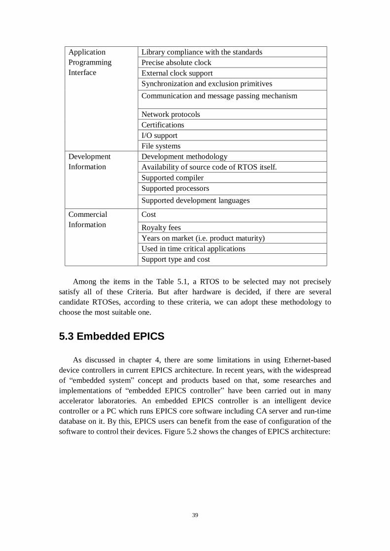
5.3 Embedded EPICS
As discussed in chapter 4, there are some limitations in using Ethernet-based device controllers in current EPICS architecture. In recent years, with the widespread of “embedded system” concept and products based on that, some researches and implementations of “embedded EPICS controller” have been carried out in many accelerator laboratories. An embedded EPICS controller is an intelligent device controller or a PC which runs EPICS core software including CA server and run-time database on it. By this, EPICS users can benefit from the ease of configuration of the software to control their devices. Figure 5.2 shows the changes of EPICS architecture:
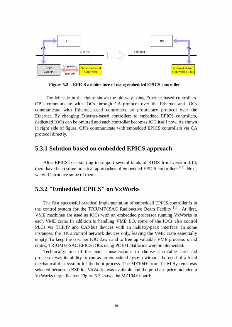
40
The left side in the figure shows the old way using Ethernet-based controllers.
OPIs communicate with IOCs through CA protocol over the Ethernet and IOCs communicate with Ethernet-based controllers by proprietary protocol over the Ethernet. By changing Ethernet-based controllers to embedded EPICS controllers, dedicated IOCs can be omitted and each controller becomes IOC itself now. As shown in right side of figure, OPIs communicate with embedded EPICS controllers via CA protocol directly.
5.3.1 Solution based on embedded EPICS approach
After EPICS base starting to support several kinds of RTOS from version 3.14, there have been some practical approaches of embedded EPICS controllers [17]. Next, we will introduce some of them.
5.3.2 "Embedded EPICS" on VxWorks
The first successful practical implementation of embedded EPICS controller is in the control system for the TRIUMF/ISAC Radioactive Beam Facility [18]. At first, VME machines are used as IOCs with an embedded processor running VxWorks in each VME crate. In addition to handling VME I/O, some of the IOCs also control PLCs via TCP/IP and CANbus devices with an industry-pack interface. In some instances, the IOCs control network devices only, leaving the VME crate essentially empty. To keep the cost per IOC down and to free up valuable VME processors and crates, TRIUMF/ISAC EPICS IOCs using PC104 platforms were implemented.
Technically, one of the main considerations to choose a suitable card and processor was its ability to run as an embedded system without the need of a local mechanical disk system for the boot process. The MZ104+ from Tri-M Systems was selected because a BSP for VxWorks was available and the purchase price included a VxWorks target license. Figure 5.3 shows the MZ104+ board:
OPI
IOCVME/PC
Network-basedController
Proprietary
protool
CAEthernet
OPI
Network-basedController (IOC)
EthernetCA
Figure 5.2 EPICS architecture of using embedded EPICS controller
41
The board has the following features: l Dual 10/100 BaseT Ethernet. l ZFx86 System-0n-a-chip (486 equivalent). l Dual RS-232 serial. l EIDE and floppy interface. l Up to 64MB of RAM. l Disk on chip Socket. At the present time, MZ104+ units are operational and have been running reliably
with EPICS R3.13.5 under VxWorks 5.4 behind a firewall. They are used to control ISAC RF, ISAC Test Stand Vacuum systems or GPIB, CAN bus sub systems.
This successful implementation inspires us the idea of running iocCore onto ITRON. While, although this scheme is a cheap and flexible way, as iocCore was originally designed for running on VxWorks, embedded VxWorks itself is common and there is nothing new.
5.3.3 "Embedded EPICS" on Linux
Another embedded EPICS solution is based on Linux. Linux is the most popular software with the free characteristic attracting large amount of users. Especially after kernel 2.6.x, the real-time characteristic has been greatly promoted. Furthermore, there are many branches of modifications which can full the hard real-time requirement. It’s a good candidate to be used as RTOS of embedded EPICS controllers [19].
As mentioned in Chapter 4.3.2, RARF control system includes one fundamental problem that a photo transceiver module in the U-Port Adopter, which is an essential CAMAC module based on a CAMAC HWY loop, is no more available. It means that it will be difficult to keep on using the current CAMAC-CIM/DIM system when a
Figure 5.3 MZ104+ and serial interface

42
U-Port Adopter will be out of order. Thus, a future structure of the CAMAC-CIM/DIM system should be investigated. Since N-DIM has compatibility with it, it is possible to use N-DIM in the RARF control system instead of the CAMAC-CIM/DIM. In fact, there is a plan to replace them in the RILAC with N-DIM gradually. However, it is difficult to replace all CAMAC-CIM/DIM in RARF to N-DIM because of budget or other reasons. Thus, it was decided to employ the Pipeline CAMAC Controller with PC104+ single board computer, CC/NET, to maintain the old CAMAC-CIM/DIM system in RARF. Figure 5.4 shows CC/NET:
The blue card on the right in the figure is the CC/NET. Its important features are
as followings: l CC/NET is a Ethernet-based intelligent controller. l System disk : CF Card (512 MB) l Operation System: Debian/GNU Linux (kernel version 2.4). l Includes original device driver and library l CAMAC HWY loop can be replaced with Ethernet by using CC/NET. On the CC/NET, Debian and EPICS R.3.14.4 were installed. The control software
of CC/NET was developed based on the N-DIM control software. The driver software can be derived from the existing software, camacLib.c, in EPICS R3.13, and developed a wrapper over the CC/NET driver to provide ISONE Standard CAMAC APIs, and then the original EPICS CAMAC-CIM/DIM device support can work as well as the standard EPICS CAMAC device support without major changes.
In this scheme, as CC/NET was custom-developed by Online Group of KEK, we can get the BSP to run Linux on it. Furthermore, Linux was in the list support by EPICS base 3.14.x, this embedded EPICS controller on Linux is straightforward.
Figure 5.4 CC/NET (developed by KEK)
43
5.3.4 Disadvantages of existent “embedded EPICS” solutions
From above applications, we can see embedded EPICS controllers are very flexible and reliable. Maybe we can image on any specific target board, we just try to select one kind of RTOS supported in EPICS list, and then we can easily gain a new kind of embedded EPICS controller. But, it’s impossible.
Usually, if we talk about embedded system, we have to discuss the BSP. A target board comes only with binary executables OS, or as an object library, the vendor must either provide a version built to run on exact hardware, or provide the routines to handle hardware specific functions and interface with the more generic binary code. They often call this target specific code a BSP, and if none is available for hardware, user either changes boards or waits for the BSP to be done.
If the target board comes with a source code OS the situation is much different. With every port, manufacture should provide the source code to the target-specific low-level routines. In almost every case, these have been built and run on at least one actual target board. This is referred as a run-time package for that particular board. If user wants to use a different board, they must alter these files to match the particular peripheral set and memory mapping, and so on.
Developing BSP is a time-consuming work. Furthermore, if we can’t gain the hardware specifications, we can’t develop the BSP.
In the examples mentioned before, either PC104+ or CC/NET, BSPs have been included to support certain RTOS to run on the hardware. In another word, the hardware decides the RTOS running on it, because few users will try to develop the BSP by themselves.
5.4 Micro-ITRON as a platform of "embedded EPICS"
Though there are preceding works along this scheme of embedded EPICS, they are all straightforward application of existing software.
In Chapter 4.1, we have introduced several kinds of Ethernet-based device controllers which are being used in our accelerator control system. Most of these controllers are running a RTOS kernel named micro-ITRON. Our main target is to port iocCore on it to make them embedded EPICS controllers.
In this way, the work involves lots of development since we are going to add a new support to EPICS base to enhance the capability of the IOC core software.
5.4.1 ITRON project and micro-ITRON
The ITRON1 Project creates standards for real-time operating systems used in embedded systems and for related specifications [20]. Since the project started, ITRON 1 TRON is an abbreviation of "The Real-time Operating system Nucleus." ITRON is an abbreviation of "Industrial TRON."
44
Technical Committee have drawn up a series of ITRON real-time kernel specifications and offered them to the public. Of these, the micro-ITRON real-time kernel specification, which was designed for consumer products and other small-scale embedded systems, has been implemented for numerous 8-bit, 16-bit and 32-bit MCUs (Micro Controller Units) and adopted in countless end products, making it an industry standard in this field. Based on these achievements, ITRON Technical Committee has broadened the scope of their standardization efforts beyond the kernel specifications to related aspects, working to expand the ITRON specifications as well as embedded system design technologies.
ITRON OS specifications were designed as follows: l Allow for adaptation to hardware, avoiding excessive hardware
virtualization. In order for an OS to take maximum advantage of the performance built into the
MCU or other hardware and deliver excellent real-time response, the specifications must avoid excessive virtualization of hardware features. Adaptation to hardware means changing the real-time OS specifications and internal implementation methods as necessary based on the kind of hardware and its performance needs, raising the overall system performance.
Specifically, the ITRON specifications make a clear distinction between aspects that should be standardized across hardware architectures and matters that should be decided optimally based on the nature of the hardware and its performance. Among the aspects that are standardized are task scheduling rules, system call names and functions, parameter names, order and meaning, and error code names and meanings. In other areas, standardization and virtualization are avoided because they might lower runtime performance. These include parameter bit size and interrupt handler starting methods, which are decided separately for each implementation. l Allow for adaptation to the application Adaptation to the application means changing the kernel specifications and
internal implementation methods based on the kernel functions and performance required by the application, in order to raise the overall system performance. In the case of an embedded system, the OS object code is generated separately for each application, so adaptation to the application works especially well.
In designing the ITRON specifications, this adaptation has been accomplished by making the functions provided by the kernel as independent of each other as possible, allowing a selection of just the functions required by each application. In practice, most micro-ITRON specification kernels are supplied with the kernel itself in library format. The selection of kernel functions is made simply by linking to the application program, at which time only the required functions are incorporated in the system. In addition, each system call provides a single function, making it easy to incorporate only the necessary functions. l Emphasize software engineer training ease The ITRON specifications employ standardization as a way of making it easier
for software developers to acquire the necessary skills. Consistency in use of terminology, system call naming and the like help ensure that once something is

45
learned, it will have wide applicability thereafter. Another way training is emphasized is by making available educational text materials. l Specification series organization and division into levels To enable adaptation to a wide diversity of hardware, the specifications are
organized into a series and divided into levels. For example, of the real-time kernel specifications developed to date, the micro-ITRON specification (version 2.0) was designed chiefly for use with small-scale systems using an 8- or 16-bit MCU, while the ITRON2 specification was intended for 32-bit processors. Each specification is further divided into levels based on the degree of need for each function. When the kernel is implemented, the level can be chosen based on the kinds of applications aimed for and their required functions. As shown in Figure 5.5. The more recently released micro-ITRON3.0 specification divides the system calls into levels, enabling this one specification to cover the range from small-scale to large-scale processors.
Specifications for distributed systems connected to networks and for
multiprocessor systems are also being standardized within the ITRON specification series. l Provide a wealth of functions2 The primitives that the kernel provides are not limited to a small number but
cover a wide range of different functions. By making use of the primitives that match the type of application and hardware, system implementers should be able to achieve high runtime performance and write programs more easily.
A theme common to several of these design principles is loose standardization. This refers to the approach of leaving room for hardware-specific and application-specific features rather than trying to apply blanket standards to the extent that runtime performance would be harmed. Loose standardization makes it possible to derive the maximum performance benefits from a diversity of hardware.
2 Appendix I, “The main functions of the micro-ITRON 3.0 specification”
Figure 5.5 Adaptation in the µItron specification

46
5.4.2 Applications in various fields
The ITRON specification kernel has been adopted by many Japanese manufacturers including the leading semiconductor firms and implemented for a wide range of different processors and applied in a large number of products in a diversity of fields. The micro-ITRON specification kernel, in particular, continues to find application to single-chip MCUs that previously could not use a real-time OS due to the memory and execution speed constraints. In the process, it is assuming a position as the world's first standard kernel specification in this field.
The ITRON specification real-time kernels registered with the TRON Association as of September 1, 1998 are listed in Appendix II. They consist of more than 40 products implemented for around 30 different processors. Although specific products have not yet been registered, support for the ITRON specification kernel is starting to come from U.S. software vendors as well. Moreover, because the micro-ITRON specification kernel is small in size and relatively easy to implement, many companies have built kernels for their own in-house use in addition to the products listed here. There are also various micro-ITRON specification kernels available as free software.
Obviously, with so many ITRON specification kernels having been implemented, they are being used in many different application fields. Table 5.2 gives some examples of the huge number of applications making use of an ITRON specification kernel:
Table 5.2 Typical ITRON specification kernel applications
Audio/Visual Equipment, Home Appliance: TVs, VCRs, digital cameras, settop box, audio components, microwave ovens, rice cookers, air-conditioners, washing machines Personal Information Appliance, Entertainment/Education: PDAs (Personal Digital Assistants), personal organizers, car navigation systems, game gear, electronic musical instruments PC Peripheral, Office Equipment: printers, scanners, disk drives, CD-ROM drives, copiers, FAX, word processors Communication Equipment: answer phones, ISDN telephones, cellular phones, PCS terminals, ATM switches, Transportation, Industrial Control, and Others automobiles, plant control, industrial robots, elevators, etc.
The earlier mentioned survey by the TRON Association also shows, the ITRON
specifications are in especially wide use in consumer products fields, where they are a de facto industry standard. Among the cases where an ITRON specification kernel is used, very many of these use an industrial implementation of the kernel, attesting to the true openness of this standard specification.

47
5.4.3 Controllers running micro-ITRON
Since micro-ITRON is so popular in industrial field, most of these Ethernet device controllers we are using now run micro-ITRON, as showed in Table 5.3:
Table 5.3 Characteristics of some typical Ethernet-based controllers
Controller Kernel CPU RAM (min)
MCU Micro-ITRON SH4 64M
e-RT33 Micro-ITRON SH4 32M
EMB-LAN100 Micro-ITRON SH3 8M
N-DIM Micro-ITRON SH4 6M
In order to run iocCore on these Ethernet-based controllers, they need to have
enough CPU power and memory. A decade ago, iocCore used to be running on Motorola 68k based CPUs with a few tens of mega-hertz of clock frequency. It is clear that CPU power of the controllers listed in Table 5.3 is enough because an SH4 CPU operates at hundreds of mega-hertz of clock frequency. As to capacity of RAM, we need a more detailed consideration since some of the device controllers have lower capacity than that of old VME CPU boards. Typically, binary file size of iocCore (EPICS 3.13) is around 1 mega-byte or less. The typical size of VxWorks kernel is also about the same size. The size of record, device and driver support should be small since the only ones that are related with the device controller itself are included. The number of database records is also small for that reason. Several mega-bytes of memory will be sufficient to run IOC core software even if we take additional memory required for communication with CA clients into account. The entire device controllers listed in Table 5.3 meets the requirement.
5.4.4 Expectation of continuity in the feature
Naturally, as long term Ethernet and Ethernet-based controllers have been chosen, we also hope micro-ITRON is a long term products.
From the information of ITRON Technical Committee, we can see they are doing best to spread this specification outside Japan. Even though the ITRON specifications have come to be called an industry standard, the work of the ITRON Project is not so well known overseas, prompting them to step up promotional work further. At the same time they are making efforts to promote the wider acceptance of the ITRON specifications overseas.
Among the specific activities, ITRON Technical Committee has established an
3 In the table 7, e-RT3 is a CPU module running micro-ITRON.
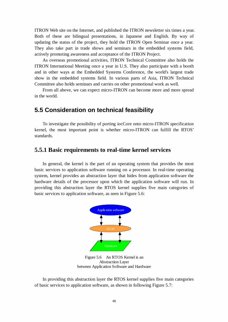
48
ITRON Web site on the Internet, and published the ITRON newsletter six times a year. Both of these are bilingual presentations, in Japanese and English. By way of updating the status of the project, they hold the ITRON Open Seminar once a year. They also take part in trade shows and seminars in the embedded systems field, actively promoting awareness and acceptance of the ITRON Project.
As overseas promotional activities, ITRON Technical Committee also holds the ITRON International Meeting once a year in U.S. They also participate with a booth and in other ways at the Embedded Systems Conference, the world's largest trade show in the embedded systems field. In various parts of Asia, ITRON Technical Committee also holds seminars and carries on other promotional work as well. From all above, we can expect micro-ITRON can become more and more spread in the world.
5.5 Consideration on technical feasibility
To investigate the possibility of porting iocCore onto micro-ITRON specification kernel, the most important point is whether micro-ITRON can fulfill the RTOS’ standards.
5.5.1 Basic requirements to real-time kernel services
In general, the kernel is the part of an operating system that provides the most basic services to application software running on a processor. In real-time operating system, kernel provides an abstraction layer that hides from application software the hardware details of the processor upon which the application software will run. In providing this abstraction layer the RTOS kernel supplies five main categories of basic services to application software, as seen in Figure 5.6:
In providing this abstraction layer the RTOS kernel supplies five main categories
of basic services to application software, as shown in following Figure 5.7:
Application software
RTOS
Hardware
Figure 5.6 An RTOS Kernel is anAbstraction Layer
between Application Software and Hardware
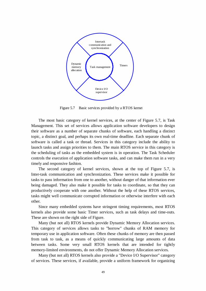
49
The most basic category of kernel services, at the center of Figure 5.7, is Task
Management. This set of services allows application software developers to design their software as a number of separate chunks of software, each handling a distinct topic, a distinct goal, and perhaps its own real-time deadline. Each separate chunk of software is called a task or thread. Services in this category include the ability to launch tasks and assign priorities to them. The main RTOS service in this category is the scheduling of tasks as the embedded system is in operation. The Task Scheduler controls the execution of application software tasks, and can make them run in a very timely and responsive fashion.
The second category of kernel services, shown at the top of Figure 5.7, is Inter-task communication and synchronization. These services make it possible for tasks to pass information from one to another, without danger of that information ever being damaged. They also make it possible for tasks to coordinate, so that they can productively cooperate with one another. Without the help of these RTOS services, tasks might well communicate corrupted information or otherwise interfere with each other.
Since many embedded systems have stringent timing requirements, most RTOS kernels also provide some basic Timer services, such as task delays and time-outs. These are shown on the right side of Figure.
Many (but not all) RTOS kernels provide Dynamic Memory Allocation services. This category of services allows tasks to "borrow" chunks of RAM memory for temporary use in application software. Often these chunks of memory are then passed from task to task, as a means of quickly communicating large amounts of data between tasks. Some very small RTOS kernels that are intended for tightly memory-limited environments, do not offer Dynamic Memory Allocation services.
Many (but not all) RTOS kernels also provide a "Device I/O Supervisor" category of services. These services, if available, provide a uniform framework for organizing
Task management
Intertaskcommunication and
synchronization
Dynamicmemoryallocation
Timers
Device I/Osupervisor
Figure 5.7 Basic services provided by a RTOS kernel
50
and accessing the many hardware device drivers that are typical of an embedded system.
In addition to kernel services, many RTOSes offer a number of optional add-on operating system components for such high-level services as file system organization, network communication, network management, database management, user-interface graphics, etc. Although many of these add-on components are much larger and much more complex than the RTOS kernel, they rely on the presence of the RTOS kernel and take advantage of its basic services. Each of these add-on components is included in an embedded system only if its services are needed for implementing the embedded application, in order to keep program memory consumption to a minimum.
Many non-real-time operating systems also provide similar kernel services. The key difference between general-computing operating systems and real-time operating systems is the need for deterministic timing behavior in the real-time operating systems. Formally, deterministic timing means that operating system services consume only known and expected amounts of time. In theory, these service times could be expressed as mathematical formulas. These formulas must be strictly algebraic and not include any random timing components. Random elements in service times could cause random delays in application software and could then make the application randomly miss real-time deadlines, a scenario clearly unacceptable for a real-time embedded system.
General computing non-real-time operating systems are often quite non-deterministic. Their services can inject random delays into application software and thus cause slow responsiveness of an application at unexpected times. If you ask the developer of a non-real-time operating system for the algebraic formula describing the timing behavior of one of its services (such as sending a message from task to task), you will invariably not get an algebraic formula. Instead the developer of the non-real-time operating system (such as Windows, UNIX or Linux) will just give you a puzzled look. Deterministic timing behavior was simply not a design goal for these general-computing operating systems.
On the other hand, real-time operating systems often go a step beyond basic determinism. For most kernel services, these operating systems offer constant load-independent timing: in other words, the algebraic formula is as simple as: T (message send) = constant , irrespective of the length of the message to be sent, or other factors such as the numbers of tasks and queues and messages being managed by the RTOS.
The most vital characteristic of a real-time operating system is how responsive the internal and external events such as external hardware interrupt, internal software signals, and internal timer interrupts. To measure deterministic timing behavior of a RTOS, we can use two measurements. One is latency, the time between the occurrence of an event and the execution of the first instruction in the interrupt code. The other is jitter, the variation in the period of nominally constant-period events. To be able to offer low latency and low jitter, the operating system must ensure that any kernel task will be preempted by the real-time task. From the micro-ITRON specification, it satisfies these conditions. Still in the

51
later testing of system, these two points should be the important criteria to benchmark the real-time performance.
5.5.2 Support for TCP/IP networking
As discussed in Chapter 3, the “backbone” of EPICS is CA which is a proprietary network protocol achieved with the Berkeley Software Distribution (BSD) socket system calls which were introduced in release 4.2 of BSD UNIX in 1983 to accomplish data communication [21].
In 4.2BSD System Manual Revised July, 1983, it defined the concept of “communication domains”, which supports communication between different machines or processes on the same machine. An operation system which is compatible with BSD socket provides access to an extensible set of communication domains. A communication domain is identified by a manifest constant defined in the file such as <sys/socket.h>. Usually, important standard domains supported by the system are the ``unix'' domain, AF_UNIX, for communication within the system, and the ``internet'' domain for communication in the DARPA internet, AF_INET. Other domains can be added to the system to be used by a wide variety of networking protocols and products. For example, examination of the socket.h in some system will show that there are large number of possible values for networking domains such as CCITT/X.25, Novell and many others.
Within a domain, communication takes place between communication endpoints known as sockets. Each socket has the potential to exchange information with other sockets within the domain. Each socket has an associated abstract type, which describes the semantics of communication using that socket. Properties such as reliability, ordering, and prevention of duplication of messages are determined by the type. The basic set of socket types is defined in <sys/socket.h> including SOCK_DGRAM, SOCK_STREAM, SOCK_RAW, SOCK_RDM, SOCK_SEQPACKET. The SOCK_DGRAM type models the semantics of datagrams in network communication: messages may be lost or duplicated and may arrive out-of-order. The SOCK_RDM type models the semantics of reliable datagrams: messages arrive unduplicated and in-order, the sender is notified if messages are lost. The send and receive operations (described below) generate reliable/unreliable datagrams. The SOCK_STREAM type models connection-based virtual circuits: two-way byte streams with no record boundaries. The SOCK_SEQPACKET type models a connection-based, full-duplex, reliable, sequenced packet exchange; the sender is notified if messages are lost, and messages are never duplicated or presented outof-order. Users of the last two abstractions may use the facilities for out-of-band transmission to send out-of-band data. SOCK_RAW is used for unprocessed access to internal network layers and interfaces and has no specific semantics.
Each socket may have a concrete protocol associated with it. This protocol is used within the domain to provide the semantics required by the socket type. For example, within the ``internet'' domain, the SOCK_DGRAM type may be implemented by the UDP user datagram protocol, and the SOCK_STREAM type may
52
be implemented by the TCP transmission control protocol, while no standard protocols to provide SOCK_RDM or SOCK_SEQPACKET sockets exist.
A socket is normally identified by a small integer which may be called as the socket descriptor. The socket mechanism is in conjunction with the TCP/IP protocols. Formally a socket is defined by a group of four numbers, these are: l The remote host identification number or address l The remote host port number l The local host identification number or address l The local host port number Users of Internet applications are normally aware of all except the local port
number, this is allocated when connection is established and is almost entirely arbitrary unlike the well known port numbers associated with popular applications. To the application programmer the sockets mechanism is accessed via a number of basic functions. These are: l create a socket: socket() l associate a socket with a network address: bind() l connect a socket to a remote network address: connect() l wait for incoming connection attempts: listen() l accept incoming connection attempts: accept() l close a socket: close() l read/write: when socket are connected, data can be written to a socket using
any of the functions write(), writev(), send(), sendto() and sendmsg(), and can be read from a socket using any of the functions read(), readv(), recv(), recvfrom() and recvmsg().
l set socket options: setsockopt(), getsockopt(). In different operating systems and environments which are compatible with BSD
socket, there are maybe tiny differences, but similar facilities and functions are provided.
Also, to use BSD socket, some of BSD APIs are needed from OS kernel, for example, fcntl() and ioctl() may be used to manipulate the properties of a socket, the function select() may be used to identify sockets with particular communication statuses, the select() function may be used to find out which ones are active when an application is using several sockets.
Although the BSD socket interface is widely used today as a TCP/IP API, the ITRON committee thought it is not appropriate for embedded systems (particularly small-scale ones) because of such problems as its large overhead and the necessity of dynamic memory management within the protocol stack. Thus, in the TCP/IP API part of ITRON specification published in May, 1998, there is only a standard TCP/IP API for ITRON-embedded systems instead of BSD socket. To fill the gap between BSD socket interface in EPICS and TCP/IP protocol stack in micro-ITRON, an API must be designed between them. This API should use ITRON TCP/IP stack as basis and supports similar or same BSD socket functions. Other API functions between kernel and BSD socket compatible functions are also need to be implemented in this API. It takes the role shown in Figure 5.8:

53
5.5.3 Availability of BSP
A BSP provides a standardized interface between hardware and the operating system [22]. A BSP does not directly access hardware. Although a BSP does provide an interface to device drivers which in turn allow the kernel to communicate with the hardware's assets such as device controllers, the microprocessor, memory, internal/external busses and so on. In the design of an embedded system, BPS is located in the prophase of the development to guarantee the application software running properly on target board. The sequence of developing an embedded system is like follows:
1. Hardware development, testing. 2. Choosing OS. 3. BSP programming. 4. Application software development. Following figure 5.9 demonstrates how OS and the developer's application
software remain hardware independent while the BSP provides an interface to the embedded computer system's architecture and hardware:
Network application
Middleware (if needded)
read(), write(), ioctl(), bind(),send(), receive(), setsockopt(),
getsockopt(), connect()...
BSD sockets API
TCP/IP protocol stack
Micro-ITRON specification
Figure 5.8 BSD socket API
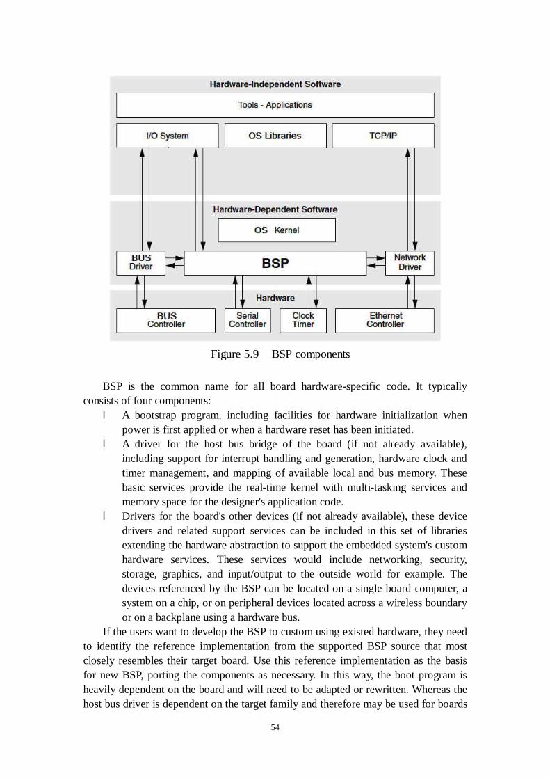
54
BSP is the common name for all board hardware-specific code. It typically
consists of four components: l A bootstrap program, including facilities for hardware initialization when
power is first applied or when a hardware reset has been initiated. l A driver for the host bus bridge of the board (if not already available),
including support for interrupt handling and generation, hardware clock and timer management, and mapping of available local and bus memory. These basic services provide the real-time kernel with multi-tasking services and memory space for the designer's application code.
l Drivers for the board's other devices (if not already available), these device drivers and related support services can be included in this set of libraries extending the hardware abstraction to support the embedded system's custom hardware services. These services would include networking, security, storage, graphics, and input/output to the outside world for example. The devices referenced by the BSP can be located on a single board computer, a system on a chip, or on peripheral devices located across a wireless boundary or on a backplane using a hardware bus.
If the users want to develop the BSP to custom using existed hardware, they need to identify the reference implementation from the supported BSP source that most closely resembles their target board. Use this reference implementation as the basis for new BSP, porting the components as necessary. In this way, the boot program is heavily dependent on the board and will need to be adapted or rewritten. Whereas the host bus driver is dependent on the target family and therefore may be used for boards
Figure 5.9 BSP components

55
in the same target family (maybe with some adaptation). Users may be able to reuse existing drivers for managing the board's other devices, using the existed device driver framework.
In our case, as the Ethernet-based device controller has been fixed, if we want to develop the BSP for a new OS, without getting the BSP for certain OS from the hardware vendor, the implementation of BSP is difficult and time consuming, there are several reasons: l As BSP programming must follow some fixed format and definitions for
different OS, existed BSP for micro-ITRON can’t be used as template for other OS such as VxWorks, Linux and so on.
l When programming BSP, the hardware technical specification such as chipset’s address is necessary. This is usually supported by the hardware manufacture. For some commercial hardware product, this may not be always open to end users.
l Each kind of Ethernet-based device controller has different architecture, such as different CPU, different peripheral equipments, even the change of memory amount, the correspondent parts of BSP are different. This makes endless modifications in programming BSP.
For these reasons, we decide to use micro-ITRON which is the original RTOS coming with hardware manufacture, BSP has been well supported and no additional fee or development are needed anymore.
5.5.4 Development environment
Handling and managing large software projects is a difficult task [23]. There are no standard recipes and methods on how to build a reliable and robust project such as EPICS which consist of thousands of source files. There are many issues may influence it, for example: portability between different OS and various compilers, size of the project, and user graphical interfaces.
However several basic tools are essential to be used to organize, store and compile EPICS base. l Cross compiler tool chain. l Make utilities. l PERL. l Debugger. There are many diversions of these tools, comparing them based on our
requirement s and choosing the suitable one must be a very important part of our work. We can summarize the possibility of our development environment approaches like following figure 5.10:
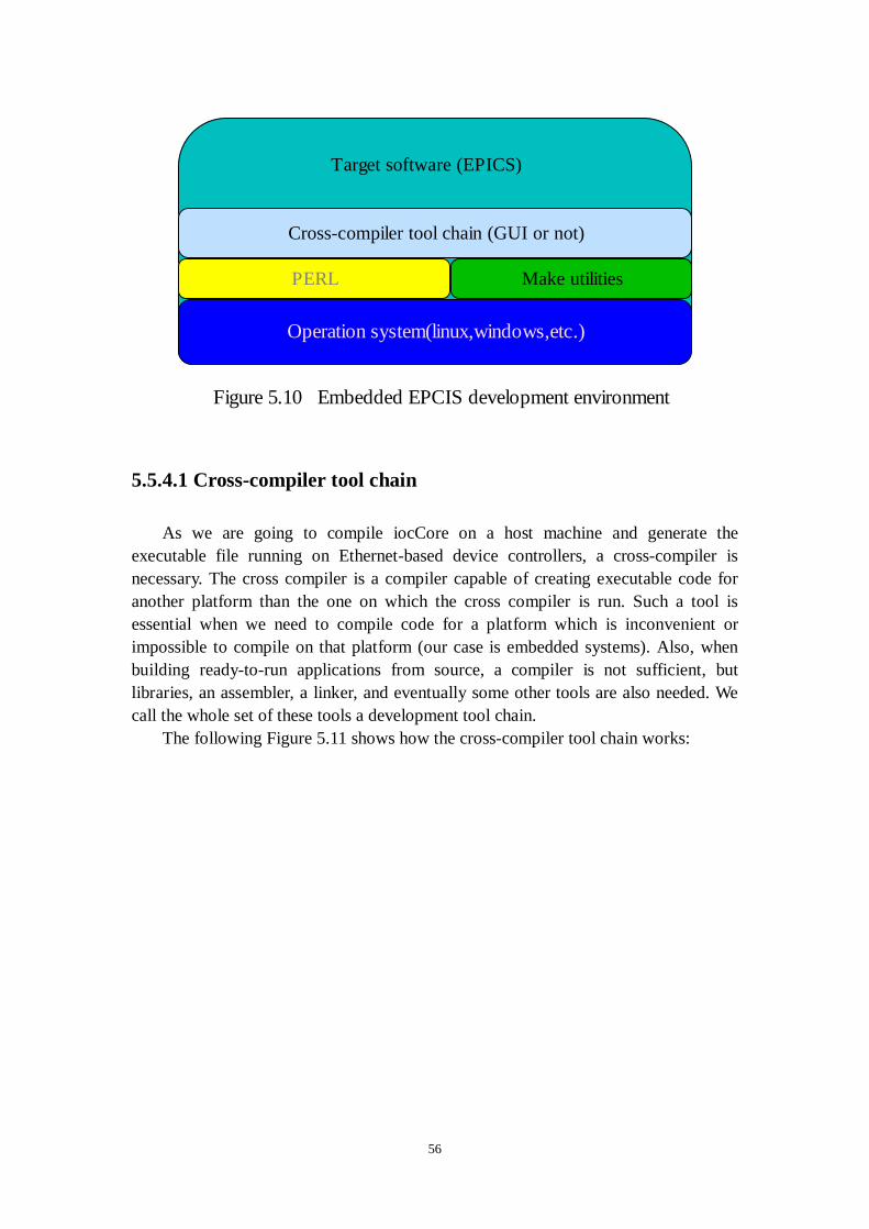
56
5.5.4.1 Cross-compiler tool chain
As we are going to compile iocCore on a host machine and generate the executable file running on Ethernet-based device controllers, a cross-compiler is necessary. The cross compiler is a compiler capable of creating executable code for another platform than the one on which the cross compiler is run. Such a tool is essential when we need to compile code for a platform which is inconvenient or impossible to compile on that platform (our case is embedded systems). Also, when building ready-to-run applications from source, a compiler is not sufficient, but libraries, an assembler, a linker, and eventually some other tools are also needed. We call the whole set of these tools a development tool chain. The following Figure 5.11 shows how the cross-compiler tool chain works:
Operation system(linux,windows,etc.)
PERL Make utilities
Cross-compiler tool chain (GUI or not)
Target software (EPICS)
Figure 5.10 Embedded EPCIS development environment

57
A good cross-compiler tool chain must be well compatible of C/C++ code and
offer abundant libraries. The GNU Compiler Collection (GCC) is one choice of producing high-quality code for embedded micro-ITRON systems as GCC support SH serious CPU [24]. The GCC is a set of programming language compilers produced by the GNU Project. It is free software distributed by the Free Software Foundation (FSF) under the GNU GPL, and is a key component of the GNU toolchain. GCC is the only application that can reliably build a cross-platform version of itself, so before building a cross-compiler, user should already install a native GCC. Also, if user needs to build/run GNU compiler under Win32, a Cygwin or MingW system is necessary. To build and install the GCC, user first must get the source code, unzip all the files, and abide by the GCC manual. The files user needs are: l GCC: ftp://ftp.gnu.org/gnu/gcc/gcc-2.95.1.tar.gz l Linker, assembler, and other utilities:
ftp://ftp.gnu.org/gnu/binutils/binutils-2.9.1.tar.gz l Run-time library:
ftp://sourceware.cygnus.com/pub/newlib/newlib-1.8.1.tar.gz But if we choosing free GNU cross-compiler, as BSP was build under another
tool chain and it may cause some problems. Finally, we choose the cross-compiler tool chain which the hardware vender using as BSP was build under it.
While, there are still two selections of cross-compiler from hardware vender. One is a GUI tool chain with relative abundant libraries; the other is a commercial and vender custom one base on free GNU compiler, with poor libraries, no GUI. As EPICS base can be well compiled with GCC, here seems we go into a dilemma as they emphasize different side between compatibility and abundant libraries. In fact, this brings us a little troublesome and will be discussed in details in chapter 6.
C source file
C preprocessor source file
Executable file
Object file
Assemble file
C preprocessor
C compiler
Assemblier
Linker
Libraries
Figure 5.11 Compiler tool chain work flow
58
5.5.4.2 Make utilities
EPICS base uses “make” to manage the whole project files. Make is one of UNIX's greatest contributions to software development. As the smallest software project typically involves a number of files that depend upon each other in various ways. If we modify one or more source files, we must re-link the program after recompiling some, but not necessarily all, of the source code. Make greatly simplifies this process by recording the relationships between sets of files, and can automatically perform all the necessary updating. For large projects such as EPICS, make becomes even more critical. The main features that EPICS using make are: l Automatic compilation of the project applications. l Choice of multiple targets and environments. l Good portability across OS platform and compilers. l A simple language to express target-source dependences. l Hierarchical approach. With these advantages, we decide to keep on using make to manage our project
files. There are different variants of the make utilities available, For example, the Microsoft program maintenance utility (NMAKE.EXE) which is an integral part of MS Visual Studio but it can work separately, and the GNU make utility which is very compatible with the UNIX make standard but needs a special software layer (CygWin32) to be functional on the MS Windows platform. Most of these applications have many common features, and the differences are minor. For this reason, basically we don’t want to use other project file managements coming with IDE of cross-compiler tool chain although they are convenient when managing not so many files in a small project.
5.5.4.3 PERL
When EPICS base work on different OS platform with make, make interacts with shell of different OS. The shell is a command programming language that originally provides an interface to the UNIX operating system. Its features include control-flow primitives, parameter passing, variables and string substitution. Command, string-valued parameters, typically file names or flags, may be passed between shell and make. Different OS shell such as the MS shell offers similar functional possibilities but has different syntax and fewer functions. Because of these differences, managing the project applications across platforms may be tricky depending on shell.
PERL is the best candidate to replace shell and batch scripts. It offers scripting techniques which cover all the imaginary possibilities of shells and batch files, plus enhanced and powerful text processing of input/output data. EPICS base uses these scripts working together with make to give incredible power of options to build sophisticated projects. So, PERL must be supported by our development environment too.
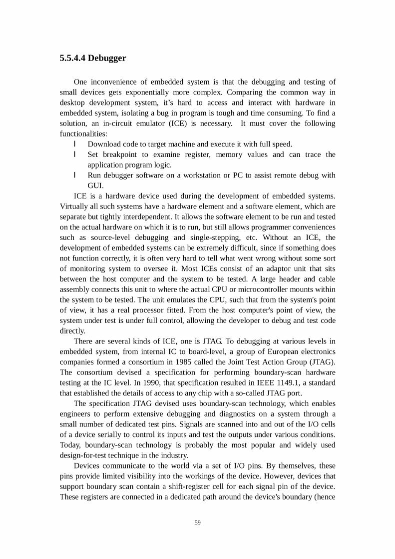
59
5.5.4.4 Debugger
One inconvenience of embedded system is that the debugging and testing of small devices gets exponentially more complex. Comparing the common way in desktop development system, it’s hard to access and interact with hardware in embedded system, isolating a bug in program is tough and time consuming. To find a solution, an in-circuit emulator (ICE) is necessary. It must cover the following functionalities: l Download code to target machine and execute it with full speed. l Set breakpoint to examine register, memory values and can trace the
application program logic. l Run debugger software on a workstation or PC to assist remote debug with
GUI. ICE is a hardware device used during the development of embedded systems.
Virtually all such systems have a hardware element and a software element, which are separate but tightly interdependent. It allows the software element to be run and tested on the actual hardware on which it is to run, but still allows programmer conveniences such as source-level debugging and single-stepping, etc. Without an ICE, the development of embedded systems can be extremely difficult, since if something does not function correctly, it is often very hard to tell what went wrong without some sort of monitoring system to oversee it. Most ICEs consist of an adaptor unit that sits between the host computer and the system to be tested. A large header and cable assembly connects this unit to where the actual CPU or microcontroller mounts within the system to be tested. The unit emulates the CPU, such that from the system's point of view, it has a real processor fitted. From the host computer's point of view, the system under test is under full control, allowing the developer to debug and test code directly.
There are several kinds of ICE, one is JTAG. To debugging at various levels in embedded system, from internal IC to board-level, a group of European electronics companies formed a consortium in 1985 called the Joint Test Action Group (JTAG). The consortium devised a specification for performing boundary-scan hardware testing at the IC level. In 1990, that specification resulted in IEEE 1149.1, a standard that established the details of access to any chip with a so-called JTAG port.
The specification JTAG devised uses boundary-scan technology, which enables engineers to perform extensive debugging and diagnostics on a system through a small number of dedicated test pins. Signals are scanned into and out of the I/O cells of a device serially to control its inputs and test the outputs under various conditions. Today, boundary-scan technology is probably the most popular and widely used design-for-test technique in the industry.
Devices communicate to the world via a set of I/O pins. By themselves, these pins provide limited visibility into the workings of the device. However, devices that support boundary scan contain a shift-register cell for each signal pin of the device. These registers are connected in a dedicated path around the device's boundary (hence

60
the name), as shown in Figure 5.12. The path creates a virtual access capability that circumvents the normal inputs and provides direct control of the device and detailed visibility at its outputs.
During testing, I/O signals enter and leave the chip through the boundary-scan
cells. The boundary-scan cells can be configured to support external testing for interconnection between chips or internal testing for logic within the chip.
To provide the boundary scan capability, IC vendors add additional logic to each of their devices, including scan registers for each of the signal pins, a dedicated scan path connecting these registers, four or five additional pins, and control circuitry. The overhead for this additional logic is minimal and generally well worth the price to have efficient testing at the board level.
The boundary-scan control signals, collectively referred to as the Test Access Port (TAP), define a serial protocol for scan-based devices. There are five pins: l TCK/clock synchronizes the internal state machine operations. l TMS/mode select is sampled at the rising edge of TCK to determine the next
state. l TDI/data in is sampled at the rising edge of TCK and shifted into the device's
test or programming logic when the internal state machine is in the correct state.
l TDO/data out represents the data shifted out of the device's test or programming logic and is valid on the falling edge of TCK when the internal state machine is in the correct state.
l TRST/reset (optional), when driven low, resets the internal state machine. The TCK, TMS, and TRST input pins drive a 16-state TAP controller state
machine.
Figure 5.12 An integrated circuit with boundary scan

61
The TAP controller manages the exchange of data and instructions. The controller advances to the next state based on the value of the TMS signal at each rising edge of TCK.
A debugger with boundary scan technique provides a flexible way to diagnostics problems in embedded system. We can use it to observe device responses by monitoring the input pins of the device. This enables easy isolation of various classes of test failures and speed up development.
5.6 Freeware vs. commercial software
Today, people show great zeal for free software/open source software [25]. As a typical example, the popularity and power of Linux are driving developers to try to use it in a growing number of embedded and real-time systems. As open source, Linux is quickly responding to the demands placed on it, both in terms of reduced footprint for embedded, and in terms of improved real-time performance.
But at the moment, a number of scheduler and preemptability enhancements are being developed and experimented with. Whether these become part of the standard kernel remains to be seen. With increased demands coming from applications like streaming media, we can expect the standard kernel to evolve in its responsiveness due to design improvements. Ongoing hardware improvements, including processor, memory, and disk performance increases, will also play an important role. However, none of these changes are likely to improve worst case response times to the tens-of-microseconds level. For now, it will be necessary to be content with multi-millisecond responsiveness from the kernel, even after adding various scheduler and preemptability patches. But this should be fully adequate for the "best efforts" bottom-line requirements of soft real-time apps like streaming multimedia, VoIP, and gaming.
To avoid this, there are multiple approaches to meeting these needs, largely because there are many different markets and applications to which Linux is being adapted, which have differing requirements. Some of these adaptations will remain add-ons or patches, while others will find there way into the mainstream Linux kernel. Like RTLinux and RTAI, they provide multi-microsecond worst case response times, by running outside the Linux sphere. Essentially, they own the system and can respond to events nearly instantaneously and without interference from Linux. RTLinux does this via a clever trick, it creates a software Interrupt controller which Linux thinks is the real thing (i.e. RTLinux emulates the system's Interrupt controller). In effect, having RTLinux (or RTAI) is like dedicating a separate processor to handle designated real-time events, since it literally commandeers the system when it needs to respond to a real-time event, in a manner that is transparent to Linux.
But there is a price to pay, which is that you must design your software to use the RTLinux-provided functions for hard-real time processes, rather than the normal Linux kernel-provided functions. The proponents of this approach contend that it's a better way to program real-time systems anyhow, i.e., partitioning the application into separate real-time and non real-time software. But it comes at the cost of two APIs:
62
one for real-time, and one for normal system functions. In short, with RTLinux (or RTAI), user can't simply run Linux applications and have them magically benefit from the presence of RTLinux (or RTAI) in the system.
Beside Linux, micro-ITRON also has free version and commercial version. While, the situation is a bit different, we can get free version of micro-ITRON from academic institute or university, but the most important thing is that we expect to get BSP from hardware manufacture instead of developing it by ourselves. It’s the key point to influence our choice of selecting RTOS and strategy to realize embedded EPICS controller on micro-ITRON.
In a word, for some general usage such desktop computer application or general using OS, freeware is a good candidate instead of commercial one. While in our case of strict restriction such BSP and hard real-time requirement, commercial micro-ITRON is best solution for us.

63
6. Porting EPICS onto a
micro-ITRON/SH4-based target
As mentioned in Chapter 4, more and more Ethernet-based device controllers are used in accelerator control system in these days. The current solution to utilize these new technologies in EPICS environment, IOC using Ethernet as field bus, has some advantages. Because it based on well-established and well-known technologies such as Ethernet and EPICS, the system can be easily managed and maintained. This solution is also flexible as other EPICS based solution, so that we can replace Ethernet-based devices from one type to the other without affecting the rest of system.
Unfortunately this solution has some disadvantages as well. This system lacks real-time responsiveness because of characteristic of Ethernet. Insufficient use of hardware and duplicate programs are other problems in this solution. To gain full benefit of the new technology and to minimize impact of these shortages, one good solution is the concept of “embedded EPICS controller”.
In Chapter 5, we investigated some implementations based on embedded EPICS controller. But they all have some shortcomings, for example, embedded EPICS controller running on Linux is short of real-time responsiveness, embedded EPICS controller running on VxWorks (RTEMS?) lacks BSP support from the hardware manufacture. These disadvantages can be avoided with a new idea to port EPICS iocCore onto micro-ITRON platform to make existing Ethernet-based device controllers into embedded EPICS controllers without losing real-time responsiveness. Before implementation, we have done many investigations to validate the possibility of porting.
VxWorks, one of commercial real time operating system kernel dominates markets, is well known by the rich supporting libraries was a primary target of EPICS base software. The development of OSI/OSD libraries in EPICS base makes it apparent that EPICS base uses just a limited part of these rich libraries. Most of functionalities covered by OSI/OSD libraries are essential to the real time kernel so that also supported by micro-ITRON. Networking based on BSD style socket interface is another essential ingredient of EPICS base. Although the standard network API in micro-ITRON is quite different from the BSD socket style, BSD socket style library for micro-ITRON is also available from the market. So essentially there seems no problem to port EPICS on micro-ITRON, but we need to confirm it by actual implementation. We also need to prove the real-time performance of EPICS on micro-ITRON using this implementation.
In this Chapter, technical details of the implementation, such as how to choose suitable products to construct R&D environment and how to re-write new OSD layer will be discussed.
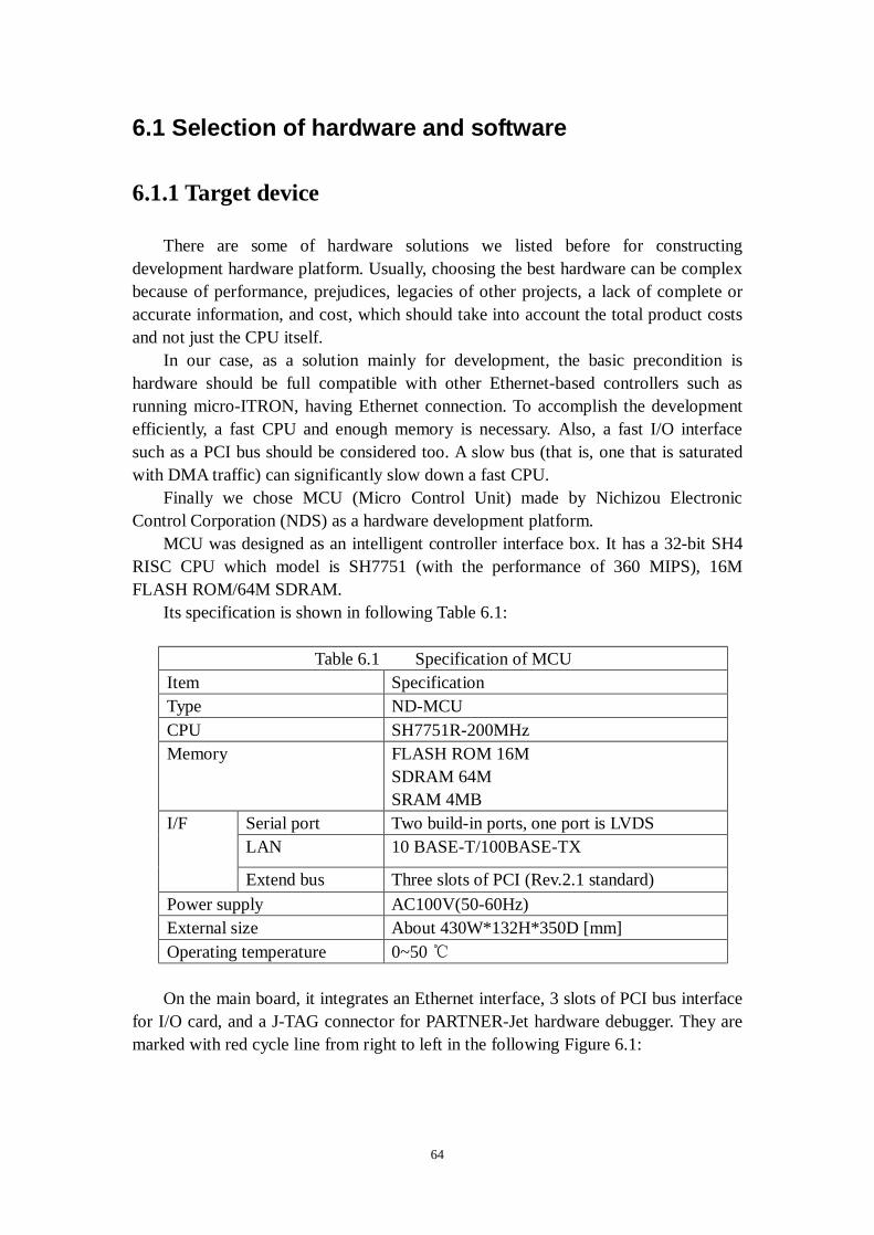
64
6.1 Selection of hardware and software
6.1.1 Target device
There are some of hardware solutions we listed before for constructing development hardware platform. Usually, choosing the best hardware can be complex because of performance, prejudices, legacies of other projects, a lack of complete or accurate information, and cost, which should take into account the total product costs and not just the CPU itself.
In our case, as a solution mainly for development, the basic precondition is hardware should be full compatible with other Ethernet-based controllers such as running micro-ITRON, having Ethernet connection. To accomplish the development efficiently, a fast CPU and enough memory is necessary. Also, a fast I/O interface such as a PCI bus should be considered too. A slow bus (that is, one that is saturated with DMA traffic) can significantly slow down a fast CPU.
Finally we chose MCU (Micro Control Unit) made by Nichizou Electronic Control Corporation (NDS) as a hardware development platform.
MCU was designed as an intelligent controller interface box. It has a 32-bit SH4 RISC CPU which model is SH7751 (with the performance of 360 MIPS), 16M FLASH ROM/64M SDRAM.
Its specification is shown in following Table 6.1:
Table 6.1 Specification of MCU Item Specification Type ND-MCU CPU SH7751R-200MHz Memory FLASH ROM 16M
SDRAM 64M SRAM 4MB
Serial port Two build-in ports, one port is LVDS LAN 10 BASE-T/100BASE-TX
I/F
Extend bus Three slots of PCI (Rev.2.1 standard) Power supply AC100V(50-60Hz) External size About 430W*132H*350D [mm] Operating temperature 0~50 ℃ On the main board, it integrates an Ethernet interface, 3 slots of PCI bus interface
for I/O card, and a J-TAG connector for PARTNER-Jet hardware debugger. They are marked with red cycle line from right to left in the following Figure 6.1:

65
6.1.2 Micro-ITRON kernel
The micro-ITRON kernel on MCU is a commercial product from MiSPO Co., Ltd. named as NORTi4. As discussed in Chap 5.5.3, the reason we chose commercial product NORTi4 instead of free one is that we can get free BSP from NDS which is designed for NORTi4. Designing BSP for other free versions of micro-ITRON kernel can be costly, time consuming and unpredictable.
MiSPO Co., Ltd. was established in 1995 as a start-up company to provide RTOS to the Japanese embedded systems market. NORTi4 is a general-purpose, very compact, full micro-ITRON compliant RTOS. It has been adopted by over 1,000 companies for various applications, including office automation equipment, cellular phones, network terminals, industrial automation, measurement equipment, and medical devices. Within NORTi4, it has included an integrated TCP/IP protocol stack for network applications, but as defined in ITRON Specification, this stack is based on micro-ITRON native TCP/IP API for embedded systems, not BSD socket compatible [26].
Furthermore, there are various middleware solutions for NORTi4 on the market, including a library supporting protocols such as BSD, PPP, SNMP, POP3/SMTP and HTTP, file management system for embedded controller is also available. This will make our system scalable in future and eliminate the possibility of incompatibility since the middleware has been well tested together with NOTRi4.
With selecting NORTi4, we expect to get good and long term support from the MISPO. Co., Ltd. Following Table 6.2 shows the building blocks of the software required to run iocCore on the MCU:
Figure 6.1 The front view of MCU produced by NDS
J-TAG connector LAN connector PCI slot
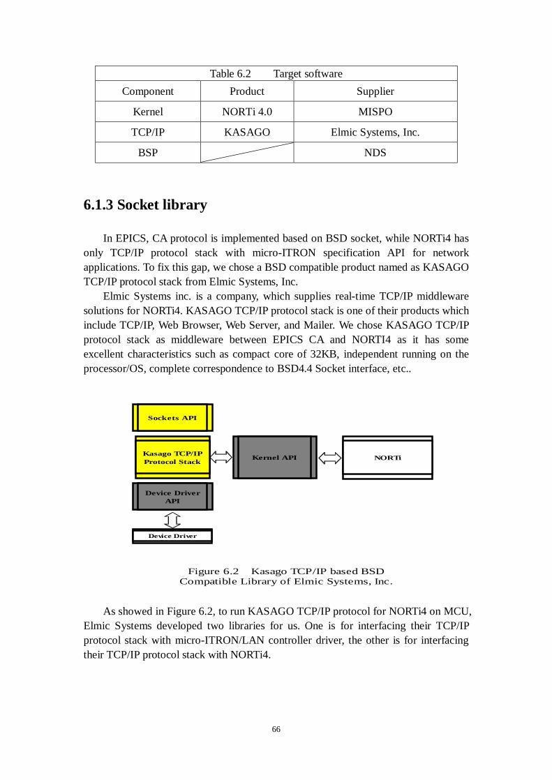
66
Table 6.2 Target software Component Product Supplier
Kernel NORTi 4.0 MISPO
TCP/IP KASAGO Elmic Systems, Inc.
BSP NDS
6.1.3 Socket library
In EPICS, CA protocol is implemented based on BSD socket, while NORTi4 has only TCP/IP protocol stack with micro-ITRON specification API for network applications. To fix this gap, we chose a BSD compatible product named as KASAGO TCP/IP protocol stack from Elmic Systems, Inc.
Elmic Systems inc. is a company, which supplies real-time TCP/IP middleware solutions for NORTi4. KASAGO TCP/IP protocol stack is one of their products which include TCP/IP, Web Browser, Web Server, and Mailer. We chose KASAGO TCP/IP protocol stack as middleware between EPICS CA and NORTI4 as it has some excellent characteristics such as compact core of 32KB, independent running on the processor/OS, complete correspondence to BSD4.4 Socket interface, etc..
As showed in Figure 6.2, to run KASAGO TCP/IP protocol for NORTi4 on MCU,
Elmic Systems developed two libraries for us. One is for interfacing their TCP/IP protocol stack with micro-ITRON/LAN controller driver, the other is for interfacing their TCP/IP protocol stack with NORTi4.
Sockets API
Device DriverAPI
Kasago TCP/IPProtocol Stack Kernel API NORTi
Device Driver
Figure 6.2 Kasago TCP/IP based BSDCompatible Library of Elmic Systems, Inc.

67
6.1.4 Cross-compiler tool chain
As discussed in 5.5.4.1, there are two kinds of candidates of cross-compiler, one is SHC, a GUI tool chain with relative abundant libraries; the other is EXEGCC, a vender custom one base on GNU tool chain, with poor libraries, no GUI. We fully investigated both of these two compilers and found the key problem of EXEGCC is that it doesn’t support two important functions of C++. In GNU GCC, there are two switches, one is “-fon-exceptions”, the other is “-fno-rtti”, the user can set these two switches ON/OFF when compilation. While in EXEGCC, these two switches were restricted for some special purposes bye the vender. That is to say, the EXEGCC don’t support exception handling and run-time type checking in user’s source code. After confirming this, we finally chose Super Hitachi Compiler (SHC, Ver. 8.0.0) with Hitachi Embedded Workshop (HEW) as the cross-compiler tool chains and so that the environment matches with that of used to develop the BSP of MCU.
SHC was developed by Renesas Technology Corp. which is the third famous semi-conductor producer in the world. In fact, Renesas is also the manufacture of SuperH family CPU. From this point, this combination should be the best one comparing with other compilers.
The interface of HEW is shown in Figure 6.3:
We can see on the left side is the list of source files, it has three categories: c file, c++ file, and asm file. All of source files can be easily managed in this file tree. The libraries and other compiler switches can be managed via the menu freely. These
Figure 6.3 GUI of HEW
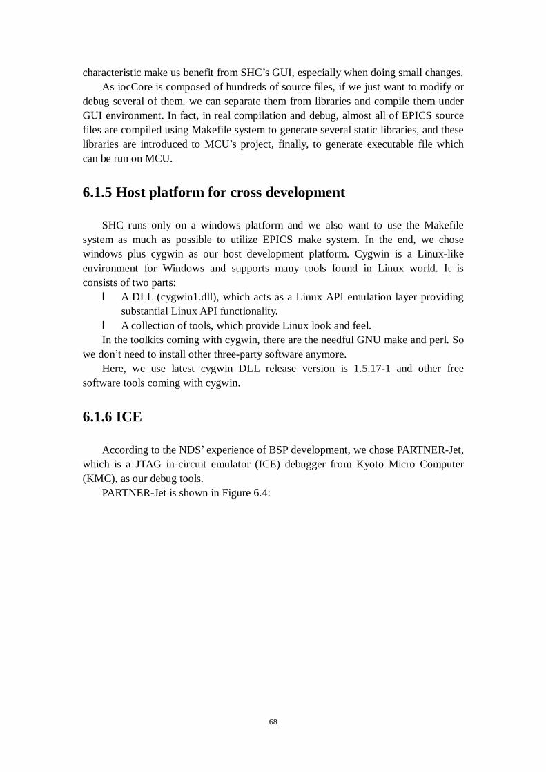
68
characteristic make us benefit from SHC’s GUI, especially when doing small changes. As iocCore is composed of hundreds of source files, if we just want to modify or
debug several of them, we can separate them from libraries and compile them under GUI environment. In fact, in real compilation and debug, almost all of EPICS source files are compiled using Makefile system to generate several static libraries, and these libraries are introduced to MCU’s project, finally, to generate executable file which can be run on MCU.
6.1.5 Host platform for cross development
SHC runs only on a windows platform and we also want to use the Makefile system as much as possible to utilize EPICS make system. In the end, we chose windows plus cygwin as our host development platform. Cygwin is a Linux-like environment for Windows and supports many tools found in Linux world. It is consists of two parts: l A DLL (cygwin1.dll), which acts as a Linux API emulation layer providing
substantial Linux API functionality. l A collection of tools, which provide Linux look and feel. In the toolkits coming with cygwin, there are the needful GNU make and perl. So
we don’t need to install other three-party software anymore. Here, we use latest cygwin DLL release version is 1.5.17-1 and other free
software tools coming with cygwin.
6.1.6 ICE
According to the NDS’ experience of BSP development, we chose PARTNER-Jet, which is a JTAG in-circuit emulator (ICE) debugger from Kyoto Micro Computer (KMC), as our debug tools.
PARTNER-Jet is shown in Figure 6.4:
69
The blue box is the main body of PARTNER-Jet, the white connecter on the left
is connected to target machine with J-TAG connector, another white connecter on the top is connected to PC via USB port, then the PC running debugger software with GUI can assist debug remotely.
With this JTAG ICE, after loading the iocCore into the emulator, we can run, step and trace into it. After the program halting at the breakpoint, we can check the value of register and memory. Under the control software running on host, the whole debug procedure is much like programming and debugging on PCs. The ICE software’s GUI is shown as figure 6.5:
Figure 6.4. KMC's PARTNER-Jet

70
Figure 6.5 GUI of ICE software
In the beginning of debug, the uses of JTAG ICE reduced the workload. But, it seems have some problems when debugging the whole system, as there are over several hundreds of source files. In our case, iocCore plus BSP is quite complicated comparing with common embedded system development. Probably, this reason makes PARTERN-Jet overloaded. This problem may need to be considered by company in future. So we use some new idea to debug the system, this will be shown in details in chapter 6.4 later.
6.2 Building EPICS-base
6.2.1 Make system and GUI-based tool
As mentioned in chapter 6.1.4, we use SHC as cross compiler and Makefile utility of Cygwin, then we can benefit from the advantages of EPICS’s Makefile system. As we are adding new supported RTOS to EPICS base, three new Makefiles about OSD part should be created following the EPICS template for cross compiling iocCore onto micro-ITRON. These configuration files are: l CONFIG.Common.itron

71
l CONFIG.Common.itron.Common l CONFIG.Common.itron-sh4 Following Table 6.3 listed a small part of Makefile for micro-ITRON:
Table 6.3 EPICS Makefile for micro-ITRON Include other Makefile
include $(CONFIG)/os/CONFIG.Common.itron
Compiler definition
CC_FOR_TARGET=shc -cpu=sh4 -ENdian=Little -debug -save_cont_reg=0 -DEFine=__SH4 CXX_FOR_TARGET=shc -cpu=sh4 -EXception -ENdian=Little -RTTI=off -debug -save_cont_reg=0 -DEFine=__SH4 AR_FOR_TARGET=optlnk LD_FOR_TARGET=optlnk LD = $(RTEMS_BASE)/bin/$(LD_FOR_TARGET) –r
Other compiler environments
GENERIC_SRC_INCLUDES = $(strip $(GENERIC_SRC_DIRS)) INSTALL_INCLUDES = $(strip $(INSTALL_INCLUDE)/os/$(OS_CLASS) $(INSTALL_INCLUDE))
In the table, we should define compiler, compiler switches and other environment
variable based on the template to fit our cases. After cross compilation, EPICS base source code will generate “.lib” files which
can be introduced to SHC’s IDE. Working with BSP source code which is originally compiled under GUI, finally, the executable file can be created. With this skillful mixture of no-GUI compilation of EPICS base and GUI compilation of BSP, we profit from the advantages of EPICS’s Makefile, SHC’s IDE and ICE later.
6.2.2 Limited capabilities of C++ compiler for embedded
systems
C++ is a powerful language but it is also large. Particularly compared to C, there are following pitfalls when using it in an embedded system [27]: l Features such as exceptions and multiple inheritances can cause additional
overheads even when you don't use them. l Simple expressions, such as initializations or template specializations, can
generate surprising amounts of code, or code that takes a long time to execute.
l Library functions, such as input/output, may drag in far more code than needed for simple uses.
To avoid these, a subset of standard C++ which is called “Embedded C++” was promoted in Japan as a sensible way to make C++ available for embedded applications. In late 1995, the Embedded C++ Technical Committee was formed and
72
provided an open standard for Embedded C++ to encourage commercial products that support this standard.
SHC is designed for embedded application. For this reason, it well supports the EC++ but not focus on fully supporting some advanced C++ characteristics. On the other hand, from EPICS base version 3.14, the some part of iocCore which was written in C language in previous version has been rewritten in C++ language. This revision brings iocCore better performance, while, some new C++ code in iocCore are not full compatible with SHC.
For this reason, we met two kinds of problems when trying to compile the iocCore with SHC, one is related with exception handler, and the other is about RTTI.
6.2.2.1 Exception handling
l Exception in C/C++ The exception handling method gives the programmers a transparent way to
handle program errors. It is available in many programming language such as Java, C++, Modula-3, etc. Here we will focus on C/C++ exception handling.
The standard C library provides several mechanisms for exception management, for example: absolute termination, conditional termination and so on. All of those are available in standard C++ as well, as the old C headers have been retained in C++ for backward compatibility, but the standard C library exception mechanisms suffer fundamental problems in C++ such as all of these mechanisms are ignorant of C++ destructors. Standard C++ exception handling avoids the above shortcomings, in it, the block of code may arose the error is started with specifying the try command and surrounding the block with curly braces. Within this block, any occurring errors which must be specified as a class can be thrown with the throw command. Immediately after the try-block is closed, the catch-block starts. Here the error handling code is placed. The following piece of pseudo code will show the idea:
try {
... throw Exception() ...
} catch ( Exception e ) {
... } In the code, Exception can be a defined class with a parameter containing an error
message and allow the class to display the message in catch clause. In this way, users can define their own exception class to be thrown and caught the error type. However, C++ standard recommends use of the standard exception class or their derived class which are defined in standard header <stdexcept> if possible. In <stdexcept>, there is a base class exception and several sub classes derived from it which are defined as
73
follows: namespace std {
class logic_error; class domain_error; class invalid_argument; class length_error; class out_of_range; class runtime_error; class range_error; class overflow_error; class underflow_error;
}; Among them, logic_error class serves as the base class for all exceptions thrown
to report errors presumably detectable before the program executes, such as violations of logical preconditions. l Exception in EPICS core
In EPCIS, not all above members of Standard Exception Handler (SEH) are used. Logic_error class is commonly used in some class’ implementations for EPICS core. A typical usage is like this:
void * netSubscription::operator new ( size_t ) // X aCC 361 { …… throw std::logic_error ( "why is the compiler calling private operator new" ); } However, in SHC’s C++ library, the exception handler library doesn’t contain
logic_error class. As a result, we privately define a new logic_error class in addition to SHC’s EH library. It was declared as follows:
namespace std { class logic_error : public exception { public: logic_error(const char *) throw();
virtual ~logic_error() throw(); virtual const char* what() const throw();
}; } Although we worked around this exception error at present, this incompatibility
problem still need to be noticed as iocCore are designed for running on various RTOS platforms now. Besides those RTOSs with compiler which is well supported SHE, there are also many tiny RTOSs or kernels which are not full compatible with SHE. Only solution is to modify the EPICS base code and make it more flexible and
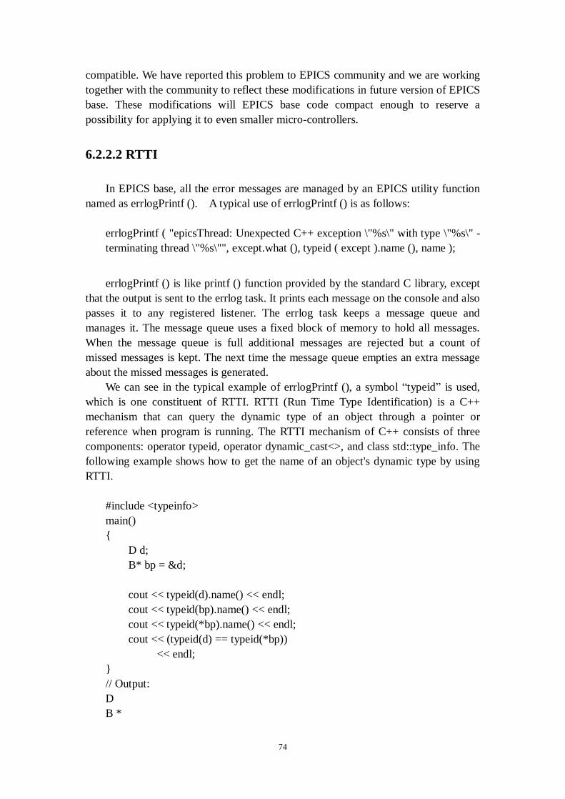
74
compatible. We have reported this problem to EPICS community and we are working together with the community to reflect these modifications in future version of EPICS base. These modifications will EPICS base code compact enough to reserve a possibility for applying it to even smaller micro-controllers.
6.2.2.2 RTTI
In EPICS base, all the error messages are managed by an EPICS utility function named as errlogPrintf (). A typical use of errlogPrintf () is as follows:
errlogPrintf ( "epicsThread: Unexpected C++ exception \"%s\" with type \"%s\" - terminating thread \"%s\"", except.what (), typeid ( except ).name (), name );
errlogPrintf () is like printf () function provided by the standard C library, except
that the output is sent to the errlog task. It prints each message on the console and also passes it to any registered listener. The errlog task keeps a message queue and manages it. The message queue uses a fixed block of memory to hold all messages. When the message queue is full additional messages are rejected but a count of missed messages is kept. The next time the message queue empties an extra message about the missed messages is generated.
We can see in the typical example of errlogPrintf (), a symbol “typeid” is used, which is one constituent of RTTI. RTTI (Run Time Type Identification) is a C++ mechanism that can query the dynamic type of an object through a pointer or reference when program is running. The RTTI mechanism of C++ consists of three components: operator typeid, operator dynamic_cast<>, and class std::type_info. The following example shows how to get the name of an object's dynamic type by using RTTI.
#include <typeinfo> main() { D d; B* bp = &d; cout << typeid(d).name() << endl; cout << typeid(bp).name() << endl; cout << typeid(*bp).name() << endl; cout << (typeid(d) == typeid(*bp)) << endl; } // Output: D B *
75
D 1 Some existing compilers don't support RTTI. Furthermore, compilers that support
it can usually be configured to disable RTTI support. Even when there's no explicit usage of RTTI in a program, the compiler automatically adds the necessary "scaffolding" to the resulting executable. To avert this, you can usually switch off your compiler's RTTI support. In SHC’s manual, it seems it can support RTTI as there is a switch can be adjusted to turn on/off to support the RTTI. But in practice, some complicated RTTI functions in EPICS base can’t be well supported. As these functions can be compiled on other platform and compiler such as GCC, we only can say SHC is not full compatible with RTTI codes in EPICS base. Since RTTI is used in EPICS only for echo error messages to help user to debug. While in our system, EPICS on MCU, neither input keyboard nor output monitor are available, so this part can be omitted. After failed in trying to compile these codes, we just move it out of EPICS base and turn off the RTTI switch in SHC. The switch about RTTI in SHC needed to be turned off to workaround a problem of unresolved external symbols upon linkage.
6.3 Implementation of OSD libraries
In EPCIS base, most code is operating system independent, i.e. the code is exactly the same for all supported operating systems. This is accomplished by providing epics defined libraries for facilities that are different on the various systems. The code is called Operating System Dependent or OSD which has multiple implementations to different systems. The OSD code is located in <base>/src/libCom/osi/os and the directory structure is like follows:
osi/
epics*.h *.cpp - A few generic c++ implementations os/
Linux/ Darwin/ RTEMS/ WIN32/ cygwin32/ default/ posix/ solaris/ VxWorks/
The osi directory contains header files which include the definitions used by user
code have a prefix epics. Each of the directories under os/<arch> contains architecture

76
dependent code. The file names begin with osd. In most cases both a header and source file are present. To add support of a new system, a new directory which contains the corresponding OSD code will be created.
6.3.1 OSD for multi-threading
In EPICS, the essential requirement for synchronized access to resource between threads is event semaphore and mutual exclusion semaphore.
The primary use of an event semaphore is for synchronization between a consumer thread which processes requests and other producer threads. An epicsEvent can be created empty or full. If it is created empty then a wait issued before a signal will block. If created full then the first wait will always succeed. Multiple signals may be issued between waits but have the same effect as a single signal.
Mutual exclusion semaphores are for situations requiring mutually exclusive access to resources. A mutual exclusion semaphore may be taken recursively, i.e. can be taken more than once by the owner thread before releasing it. Recursive takes are useful for a set of routines that call each other while working on a same mutually exclusive resource.
NORTi4 supports both these two semaphores. Comparing with RTEMS or VxWorks, NORTi4 has different format when calling these functions. The following Table 6.4 gives an example to show the difference between RTEMS and NORTi4 when creating an event semaphore:
Table 6.4 Difference (creating event semaphore) between RTEMS and NORTi4
RTEMS rtems_semaphore_create (rtems_build_name ('B', c3, c2, c1),initialState,RTEMS_FIFO|RTEMS_SIMPLE_BINARY_SEMAPHORE|RTEMS_NO_INHERIT_PRIORITY|RTEMS_NO_PRI
ORITY_CEILING|RTEMS_LOCAL, 0,&sid) NORTi4 ercd = acre_sem(&pevt->csem);
We can see, in RTEMS, the parameter of event can be set dynamically when
calling “rtems_semaphore_create”. While in NORTi4, before calling “acre_sem”, the parameter must be stored in a structure in memory as the argument of “acre_sem” is address which stores that structure. So we define a T_EVENT structure which includes T_CSEM structure:
typedef struct { T_CSEM csem; ID eventid; } T_EVENT;
then, before creating event semaphore, the T_CSEM structure would be initialized as following:
pevt->csem.sematr = TA_TFIFO; pevt->csem.isemcnt = initialState;
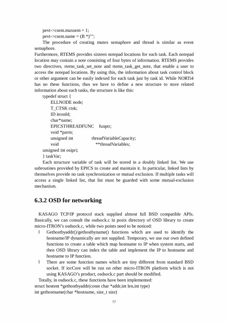
77
pevt->csem.maxsem = 1; pevt->csem.name = (B *)""; The procedure of creating mutex semaphore and thread is similar as event
semaphore. Furthermore, RTEMS provides sixteen notepad locations for each task. Each notepad location may contain a note consisting of four bytes of information. RTEMS provides two directives, rtems_task_set_note and rtems_task_get_note, that enable a user to access the notepad locations. By using this, the information about task control block or other argument can be easily indexed for each task just by task id. While NORTi4 has no these functions, thus we have to define a new structure to store related information about each tasks, the structure is like this:
typedef struct { ELLNODE node; T_CTSK ctsk; ID itronId; char *name; EPICSTHREADFUNC funptr; void *parm; unsigned int threadVariableCapacity; void **threadVariables; unsigned int osipri; } taskVar; Each structure variable of task will be stored in a doubly linked list. We use
subroutines provided by EPICS to create and maintain it. In particular, linked lists by themselves provide no task synchronization or mutual exclusion. If multiple tasks will access a single linked list, that list must be guarded with some mutual-exclusion mechanism.
6.3.2 OSD for networking
KASAGO TCP/IP protocol stack supplied almost full BSD compatible APIs. Basically, we can consult the osdsock.c in posix directory of OSD library to create micro-ITRON’s osdsock.c, while two points need to be noticed: l Gethostbyaddr()/gethostbyname() functions which are used to identify the
hostname/IP dynamically are not supplied. Temporary, we use our own defined functions to create a table which map hostname to IP when system starts, and then OSD library can index the table and implement the IP to hostname and hostname to IP function.
l There are some function names which are tiny different from standard BSD socket. If iocCore will be run on other micro-ITRON platform which is not using KASAGO’s product, osdsock.c part should be modified.
Totally, in osdsock.c, these functions have been implemented: struct hostent *gethostbyaddr(const char *addr,int len,int type) int gethostname(char *hostname, size_t size)

78
epicsShareFunc SOCKET epicsShareAPI epicsSocketCreate (int domain, int type, int protocol ) epicsShareFunc int epicsShareAPI epicsSocketAccept (int sock, struct sockaddr * pAddr, osiSocklen_t * addrlen ) void osiSockRelease() epicsShareFunc void epicsShareAPI epicsSocketDestroy ( SOCKET s ) int osiSockAttach() epicsShareFunc unsigned epicsShareAPI ipAddrToHostName (const struct in_addr *pAddr, char *pBuf, unsigned bufSize) epicsShareFunc int epicsShareAPI hostToIPAddr(const char *pHostName, struct in_addr *pIPA)
6.3.3 OSD for time functions
In EPICS, precise time resolution (millisecond level) is necessary for real time requirements. But in NORTi4, time function is very poor. Only a 32 bit structure SYSTIM are defined to count the ticks from the system starts, get_tim() to read ticks and set_tim() to change ticks. About BSP, there are two functions to operate RTC (Real Time Clock, precision is second level), so we can’t measure time precisely by using RTC (Real Time Clock).
We implemented some APIs to fix this gap. In fact, nearly all of the time functions required by EPICS have to be created by ourselves. Reference to UNIX system, time is counted from Epoch (1970/1/1, 00:00:00, GMT). To eliminate the difference and simply the case, we set the start time of system by defining same Epoch as UNIX system. When system start, we use function coming with BSP to get RTC time, calculate the elapse time since Epoch. Each time wanting to get the current time, first get the ticks in NORTi4, then plus the elapse time, we can get current time (precision is millisecond). Implementation of osdtime.c is straightforward, including following functions: int epicsTimeGetCurrent (epicsTimeStamp *pDest) int epicsTimeGetEvent (epicsTimeStamp *pDest, int eventNumber) void clockInit(void) int epicsTime_gmtime ( const time_t *pAnsiTime, struct tm *pTM ) int epicsTime_localtime ( const time_t *clock, struct tm *result )
6.4 Debugging and testing
As mentioned in Chapter 6.1.6, although we have estimated the difficulty of debugging, debug procedure is still more troublesome then we expected even we have the PARTER-Jet debugger.
At the beginning of debugging OSD library, PARTER-Jet did great help for us. But when debugging the full system, as iocCore is composed of several hundreds of source files, it’s really hard to trace files one by one only by debugger. In fact, there
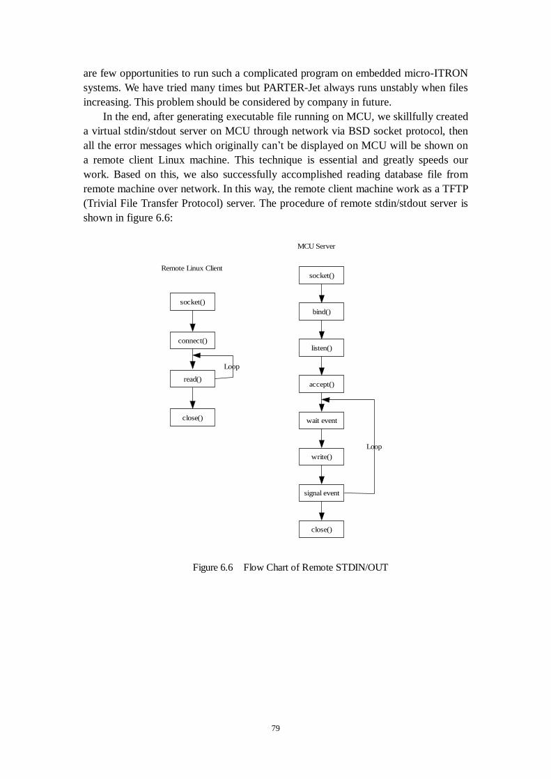
79
are few opportunities to run such a complicated program on embedded micro-ITRON systems. We have tried many times but PARTER-Jet always runs unstably when files increasing. This problem should be considered by company in future.
In the end, after generating executable file running on MCU, we skillfully created a virtual stdin/stdout server on MCU through network via BSD socket protocol, then all the error messages which originally can’t be displayed on MCU will be shown on a remote client Linux machine. This technique is essential and greatly speeds our work. Based on this, we also successfully accomplished reading database file from remote machine over network. In this way, the remote client machine work as a TFTP (Trivial File Transfer Protocol) server. The procedure of remote stdin/stdout server is shown in figure 6.6:
socket()
connect()
read()
close()
socket()
bind()
listen()
accept()
write()
close()
wait event
signal event
Remote Linux Client
MCU Server
Loop
Loop
Figure 6.6 Flow Chart of Remote STDIN/OUT

80
7. Performance evaluation of the EPICS on
micro-ITRON
We are now going to study the real time characteristic or deterministic performance of new micro-ITRON IOC. Since Linux IOC has been extensively used in industrial control systems [28], by comparing with it, we can know if the new embedded EPICS controller is more or less agile than those Linux ones, so we performed the real-time performance test of micro-ITRON on the MCU platform, and then compares it in detail to Linux on a common PC in the following measurement.
This test is a basic measurement of the whole system, both hardware and software performance. While we should note the test is on different hardware platform, and is independent of calculation loads as control logic is very simple. The reason is all these loads would typically be independent of OS used.
7.1 Theory of the jitter test
One of the fundamental criteria for evaluating performance of a real-time operating system is periodic jitter. Periodic jitter as shown in Figure 7.1 refers to the variations in time that a repetitive event experience as it happens. An event can be an interrupt generated by hardware external to the CPU or it can be a signal internal to the operating system such as a notification to start a task periodically to output a signal.
The repetitive task is at the heart of sampled-data control of mechanical devices.
The models of the device to be controlled are calculated on the assumption that the
t
Event jitter
t0
t1
Event request
Figure 7.1 Jitter definition

81
sample time is known and fixed. The control algorithms are, in turn, calculated from the device model, reinforcing the dependence on a known and stable sample time. Any jitter in the sample time leads to imprecision in the control-system performance.
To test the jitter on RTOS, we create a repeat task that uses a function to generate signals on an analogue signal output device, and then an oscilloscope or other hardware counter can monitor periodic signals. The tests we ran are simple and direct, as the iocCore has been running on both embedded micro-ITRON and Linux controllers. We don't need to program on OS directly and just need to use EPICS to accomplish it. Finally, on each embedded EPICS controller, a runtime database was created which contains an output record and a calc record. The calc record generates square wave signals repeatedly. The output record gets the raw value from calc record, and then outputs voltage signals through a D/A card. The period of signal can be easily adjusted with modifying the SCAN field of output record dynamically. In the test, we set the period sequence as: 0.5/0.4/0.2/0.1/0.05/0.04/0.02/0.01/0.005/0.004, the unit is second. The outline of jitter test is shown in following Figure 7.2:
All parts included in the dashed pane of the figure are in embedded EPICS box. A
high-speed memory scope, indicated as "Oscilloscope" in the figure, captures output signal to measure jitter timing.
7.2 Hardware platform for the comparison
The test sets here we used for micro-ITRON and for Linux are not same. To test jitter on micro-ITRON, we use MCU, the primary target of "EPICS on ITRON". To test jitter on Linux, we use a common PC running Redhat Linux kernel version 2.4.18 which has one millisecond timer resolution4 . Their configuration is shown in table 7.1:
4 The kernel parameter HZ is modified to 1024 from standard 100.
Calcrecord
Squarewave signal
Outputrecord
Digitalsignal
DAcard Oscilloscope
Period scan
Voltagesignal
Embedded EPICS controller
Figure 7.2 Outline of jitter test

82
Table 7.1 Comparison (hardware platform) between Linux and
micro-ITRON Linux platform Micro-ITRON platform CPU 3.2GHz Pentium4 200MHz SH4 DRAM 1G 16M DISK 40G Hard disk 64M Flash ROM DA card DA12-4 PCI-360116
On Linux machine, a 12 bit DA card was used. On MCU, a 16 bit AD/DA card
was used. They both have very quick response speed, which is less than 10 micro seconds, since we can estimate the jitter will be several hundreds of micro seconds [29], the difference of two kinds of cards will not influence the result. Following Table 7.2 is the specification of these cards:
Table 7.2 Specification of two kinds of DA cards
Model DA12-4(PCI) PCI-360116 Manufacture Contec CO., LTD. Interface Corporation Type DA AD/DA Channel 8 2 Bits 16 12 Convert speed 10μs 10μs Output -10V~10V -10V~10V
In the test, we use a same oscilloscope (Tektronix TDS3014B Digital
Oscilloscope), it has 100 MHz bandwidth and 1.25GS/s sample rate. Voltage signal from the DA card is output to channel 3 of oscilloscope.
7.3 Detailed jitter test
7.3.1 Jitter on embedded Linux controller

83
We run all tests with different period from the range of 500 milliseconds to 4 milliseconds and record the jitter data. Following figure 7.3 is a typical one of output signal with the 50 milliseconds period. Trigger of oscilloscope is set to pick up rising step of square wave generated by periodic scan of calc record.
The gauge in the middle of screen is 50 ms from the trigger, and the vertical
purple line is the actual output signal. As we can see, the earliest output signal lagged the gauge around 700 micro seconds, the latest signal lagged the gauge around 1500 micro seconds, and the jitter is about 800 microseconds.
We noticed that in the Linux test, the occurrences of output signal are always lagged after the gauge. This delay is caused because the task may not be scheduled immediately even if we set the task highest real-time priority, as Linux kernel 2.4.6 is non-preempt able. The standard kernel is based on the classical monolithic structure, in which the consistency of kernel structures is enforced by allowing at most one execution flow in the kernel at any given time. This is achieved by disabling preemption when an execution flow enters the kernel, i.e., when an interrupt fires or when a system call is invoked. Consider an example if kernel preemption is disabled for some reason, such as ISRs from device drivers. Task will be put into ready queue or be woken up from ready queue later after interrupts are re-enabled. So in the application of standard Linux kernel, maximum delay time can be equal to the maximum length of a system call plus the processing time of all the interrupts that fire before returning to user mode. This non-preempt able characteristic makes standard Linux can’t be used in strictly real-time requirement environment.
Figure 7.3 Jitter on Linux
1500 µs
700 µs

84
7.3.2 Jitter on embedded micro-ITRON controller
Following Figure 7.4 shows the jitter on embedded micro-ITRON controller at the period of 50 milliseconds:
Here we can see the earliest occurrence of the falling edge is tightly around the
gauge and most of output signal is very close to expected time. The reason purple line is ahead of gauge is the tiny shift of clock between test machine and oscilloscope. However, the jitter on micro-ITRON is still several hundreds of microseconds or one millisecond level. We investigated the code in EPICS which related with calculation the period, one part is like follows: epicsTimeDiffInSeconds (const epicsTimeStamp *pLeft, const epicsTimeStamp *pRight) {
return epicsTime (*pLeft) - epicsTime (*pRight); } epicsTime is a class defined in EPICS. Even in very fast scan period, such as 0.005 second, each time iocCore calculate the time difference using this function, the new
Figure 7.4 Jitter on micro-ITRON
1000 µs

85
object must be created and deleted. It increased the overhead of CPU and made additional one tick error. To confirm this, we replace the code about time difference calculation in EPICS with our own and did the same test again. The result reported in the next section is consistent with our guess.
7.3.3 Jitter on embedded micro-ITRON controller with the
modified time-difference calculation routine
Following figure shows jitter on micro-ITRON while using our own code of period calculation. Modified code does not use C++ class and does not suffer from the overhead of object creation and deletion. With this modification, the jitter decreased evidently. In the figure, it’s less than two hundreds of microseconds. It shows the good real-time characteristic of micro-ITRON. It should be noted that the time scale in the figure x is 400 microseconds/division while it is 40 microseconds/division in the Figure 7.5:
In our test, besides the time-difference calculation routine in EPICS can bring one
tick error in jitter, another reason to influence the test accuracy is time resolution of OS. The default time resolution of standard Linux kernel 2.4.6 and NORTi4 is 10 milliseconds. In one experiment using Linux IOC to control inverse pendulum we
80 µs
40 µs
Figure 7.5 Jitter on embedded micro-ITRONwith the modified time-difference calculation routine
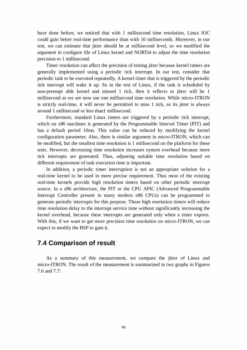
86
have done before, we noticed that with 1 millisecond time resolution, Linux IOC could gain better real-time performance than with 10 milliseconds. Moreover, in our test, we can estimate that jitter should be at millisecond level, so we modified the argument in configure file of Linux kernel and NORTi4 to adjust the time resolution precision to 1 millisecond.
Timer resolution can affect the precision of testing jitter because kernel timers are generally implemented using a periodic tick interrupt. In our test, consider that periodic task to be executed repeatedly. A kernel timer that is triggered by the periodic tick interrupt will wake it up. So in the test of Linux, if the task is scheduled by non-preempt able kernel and missed 1 tick, then it reflects to jitter will be 1 millisecond as we are now use one millisecond time resolution. While micro-ITRON is strictly real-time, it will never be permitted to miss 1 tick, so its jitter is always around 1 millisecond or less than1 millisecond.
Furthermore, standard Linux timers are triggered by a periodic tick interrupt, which on x86 machines is generated by the Programmable Interval Timer (PIT) and has a default period 10ms. This value can be reduced by modifying the kernel configuration parameter. Also, there is similar argument in micro-ITRON, which can be modified, but the smallest time resolution is 1 millisecond on the platform for these tests. However, decreasing time resolution increases system overhead because more tick interrupts are generated. Thus, adjusting suitable time resolution based on different requirement of task execution time is important.
In addition, a periodic timer interruption is not an appropriate solution for a real-time kernel to be used in more precise requirement. Thus most of the existing real-time kernels provide high resolution timers based on other periodic interrupt source. In a x86 architecture, the PIT or the CPU APIC (Advanced Programmable Interrupt Controller present in many modern x86 CPUs) can be programmed to generate periodic interrupts for this purpose. Those high resolution timers will reduce time resolution delay to the interrupt service time without significantly increasing the kernel overhead, because these interrupts are generated only when a timer expires. With this, if we want to get more precision time resolution on micro-ITRON, we can expect to modify the BSP to gain it.
7.4 Comparison of result
As a summary of this measurement, we compare the jitter of Linux and micro-ITRON. The result of the measurement is summarized in two graphs in Figures 7.6 and 7.7:
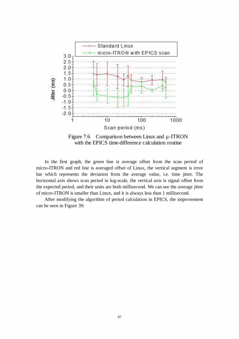
87
In the first graph, the green line is average offset from the scan period of micro-ITRON and red line is averaged offset of Linux, the vertical segment is error bar which represents the deviation from the average value, i.e. time jitter. The horizontal axis shows scan period in log-scale, the vertical axis is signal offset from the expected period, and their units are both millisecond. We can see the average jitter of micro-ITRON is smaller than Linux, and it is always less than 1 millisecond. After modifying the algorithm of period calculation in EPICS, the improvement can be seen in Figure 39:
Figure 7.6 Comparison between Linux and µ-ITRONwith the EPICS time-difference calculation routine
88
In the second graph, the green line is average offset from requested period with modified code on micro-ITRON and the red line is average offset with original EPICS scan period code on Linux. The comparison result proves our guess that object operation in C++ code brings additional time error. Further more, it shows micro-ITRON itself has good real-time performance and can be used for strict real-time requirement.
Figure 7.7 Comparison between Linux and µ-ITRONwith modified EPICS time-difference calculation routine
89
8. Conclusion and discussions
In this work, we have ported EPICS core software including EPICS database and CA server to the micro ITRON platform. We also measured the basic performance of EPICS software on micro ITRON and compared it with that of EPICS on Linux. Despite the fact that CPU capacity for micro ITRON is limited compared to the Linux IOC, EPICS on micro ITRON shows better real time respondence. It proves our argument in the chapter 4 of this thesis.
There have been several approaches before to implement embedded EPICS controllers. Comparing them, our porting EPICS core software onto micro-ITRON is a fully new attempt. It’s challengeable as micro-ITRON is only a kernel of RTOS and only supports the basic and minimum functions which are essential to run iocCore. Another preceding work is taken by the J-PARC control group in JAERI. They just ported the CA server part of the EPICS software and combined it with the custom software specific to the application. They also use ITRON API for TCP/IP stack instead of using BSD socket library. Because of these deviation from the original EPICS source code the long-term maintainability is in question. In our project, we considered the idea of all of the preceding work and tried to keep the original source code as much as possible except OSD part of EPICS software. We also feedback the our knowledge and experience in the development to the EPICS community so that it is almost guaranteed that future version of EPICS will also work on micro ITRON, at least with minor modification. Since we have ported an essential part of EPICS IOC core software, the runtime database and the CA server, users of EPICS can enjoy ease of configuration of the software to control their devices. Even the user who is not familiar with the software on the embedded controller now can utilize embedded controller for their device. This embedded EPICS controller on micro-ITRON extends the classical theory of DCS in EPICS control system. It makes it easy to integrate modern intelligent devices into the EPICS based control systems such as KEKEB accelerator controls without losing real time respondence. It definitely contributed to bring the controls to the new stage for high performance accelerators.

90
Acknowledgments
I would like to express my tremendous gratitude to my supervisor, Professor S. Kurokawa, for his patience, guidance and support during the three years of my study under his supervision.
I would like to show great appreciation to Professor T. Katoh, for his guidance, suggestions and encouragement.
I would like to acknowledge to Dr. N. Yamamoto for his advice and ideas, and also his wonderful help in dealing with the problems concerning my study and research.
I am particularly indebted to Mr. J. Odagiri for his continuous support, suggestions and advice. We worked for many days and night. I learned much precious experience and knowledge from him.
I am also thankful for Mr. A. Akiyama who supported this research especially in the setup of the hardware system.
I would also like to take the opportunity to thank Dr. K. Furukawa for his precious suggestion at the beginning of the work.
Last, but not least, I would like to thank all the members of the KEKB control group and J-PARC control group.
91
Bibliography
[1] J.F. Skelly and J.T. Morris, Brookhaven National Laboratory, "Design, Evolution and Impact of the AGS/RHIC Control System", http://epaper.kek.jp/ica99/papers/wc1p05.pdf. [2] J. KISHIRO, "Control systems of the KEK accelerator complex". [3] J. Chiba, K. Furukawa,et al., "PRESENT STATUS OF THE J-PARC CONTROL SYSTEM", http://icalepcs2003.postech.ac.kr/Proceedings/PAPERS/MO101.PDF [4] Boyer, Stuart A. SCADA: Supervisory Control and Data Acquisition. North Carolina: Research Triangle, 1993. [5] Stephen A. Lewis, "Overview of the Experimental Physics and Industrial Control System: EPICS". [6] Martin R. Kraimer, Janet Anderson, Andrew Johnson, Eric Norum, Jeff Hill, Ralph Lange, "EPICS: Input / Output Controller Application Developer’s Guide Release 3.14.1 20DEC2002". [7] Jeffrey O. Hill, "EPICS R3.14 CA Reference Manual". [8] A. G¨otz, ESRF, et al.,"MIDDLEWARE IN ACCELERATOR AND TELESCOPE CONTROL SYSTEM", Proceedings of ICALEPCS2003, Gyeongju, Korea. [9] M. Kraimer et.al, "EPICS: Porting iocCore to Multiple Operating Systems," ICALEPCS'99, Trieste,Italy, Oct. 1999. [10] J. Odagiri, J. Chiba, K. Furukawa, N. Kamikubota, T. Katoh, H. Nakagawa and N. Yamamoto, "EPICS DEVICE/DRIVER SUPPORT MODULES FOR ETHERNET-BASED INTELLIGENT CONTROLLERS", Proceedings of ICALEPCS2003, Gyeongju, Korea. [11] M. Komiyama et al., "Control System for the RIKEN Accelerator Research Facility and RI-Beam Factory", the 17th International Conference on Cyclotrons and Their Applications, Tokyo, Oct. 18-22, 2004. [12] J. Chiba et al., "A Control System of the Joint-Project Accelerator Complex", ICALEPCS'2003, Gyeongju, Korea, Oct. 2003. [13] Y.Yano, et al., "RI Beam Factory Project at RIKEN," Proc. of 16th Int. Conf. on Cyclotrons and their Applications, East Lansing, U.S.A. (2001) p.161. [14] K. Furukawa, et al., "Network based EPICS Drivers for PLCs and Measurement Stations", ICALEPCS'99, Trieste, Italy, 1999, p409. [15] Martin R. Kraimer, "EPICS: OPERATING-SYSTEM-INDEPENDENT DEVICE/DRIVER SUPPORT", Proceedings of ICALEPCS2003, Gyeongju, Korea. [16] C.Walls, “RTOS for Microcontroller Applications,” Electronic Engineering, v 68, n 831, pp. 57-61, 1996. [17] R. Lange, J. B. Anderson, A. N. Johnson M. R. Kraimer, W. E. Norum, L. R. Dalesio, J. O. Hill, "EPICS: RECENT DEVELOPMENTS AND FUTURE PERSPECTIVES".

92
[18] G. Waters, et.al, "TRIUMF/ISAC EPICS IOCs Using a PC104 Platform", ICALEPCS'2003, Gyeongju, Korea, Oct. 2003. [19] Aeolean Inc.,"Introduction to Linux for Real-Time Control". [20] ITRON’s website, http://tron.um.u-tokyo.ac.jp/TRON/ITRON/home-e.html. [21] William Joy, Eric Cooper, Robert Fabry,Samuel Leffler, Kirk McKusick and David Mosher, “4.2BSD System Manual”, Revised July, 1983. [22] Ron Fredericks, Wind River, "FAQ: What is a Board Support Package", http://www.windriver.com/products/bsp_web/bsp_architecture.html [23] David B. Stewart, "Miniature Software for Large Pervasive Computing Applications". [24] Bill Gatliff, “Embedding with GNU: The GNU Compiler and Linker”, http://www.embedded.com/2000/0002/0002feat2.htm [25] T. Straumann, SSRL, Menlo Park, "OPEN SOURCE REAL TIME OPERATING SYSTEMS OVERVIEW", 8th International Conference on Accelerator & Large Experimental Physics Control Systems, 2001, San Jose, California. [26] Real-time Multitasking OS based on μITRON 4.0, NORTi4 User's Guide. [27] P.J. Plauger ,"Standard C++ Library Reference". [28] Luca Abeni, Ashvin Goel, Charles Krasic, Jim Snow, Jonathan Walpole, "A Measurement-Based Analysis of the Real-Time Performance of Linux". [29] Atsuyoshi Akiyama, Jiang Geyang, Jun-Ichi Odagiri, Noboru Yamamoto, "Controlling an inverted pendulum using Linux-IOC", The 14th Symposium on Accelerator Science and Technology, Tsukuba, Japan, November 2003.
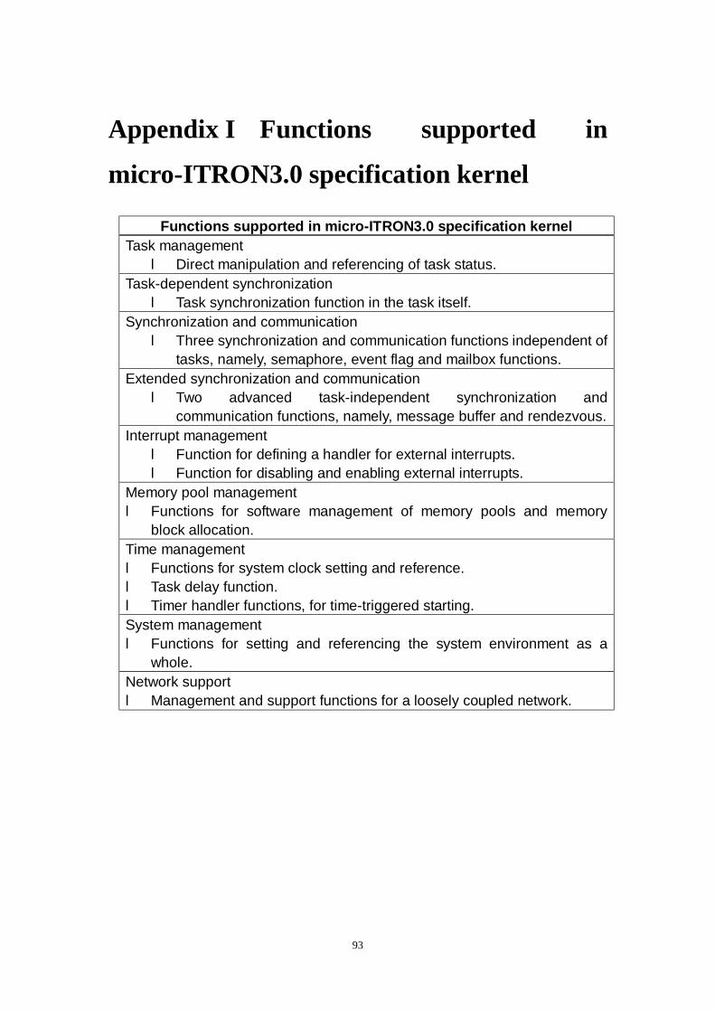
93
Appendix I Functions supported in
micro-ITRON3.0 specification kernel
Functions supported in micro-ITRON3.0 specification kernel Task management l Direct manipulation and referencing of task status.
Task-dependent synchronization l Task synchronization function in the task itself.
Synchronization and communication l Three synchronization and communication functions independent of
tasks, namely, semaphore, event flag and mailbox functions. Extended synchronization and communication l Two advanced task-independent synchronization and
communication functions, namely, message buffer and rendezvous. Interrupt management l Function for defining a handler for external interrupts. l Function for disabling and enabling external interrupts.
Memory pool management l Functions for software management of memory pools and memory
block allocation. Time management l Functions for system clock setting and reference. l Task delay function. l Timer handler functions, for time-triggered starting. System management l Functions for setting and referencing the system environment as a
whole. Network support l Management and support functions for a loosely coupled network.

94
Appendix II ITRON-specification kernel
implementations
ITRON-specification kernel implementations (Products registered with the TRON Association as of Sep. 1, 1998)
Company Processor Specification V20
V33A
V25 V55PI
ITRON1 ERG Co., Ltd.
SH2, VR4100/VR4300, TMS470R1x, SR320
µITRON3.0
Firmware Systems Inc. ARM7TDMI Series µITRON3.0
F2MC-16LX/16L/16/16H/16F Family F2MC-8L Family
µITRON2.0
FR Family
FUJITSU LIMITED
SPARClite Series
µITRON3.0
H8/300 H8/500
H8/300H
SH
H8S
µITRON2.0
SH-1, SH-2 Series
SH2-DSP Series
Hitachi, Ltd.
SH3 Series
µITRON3.0
M32 Family 7700 Family
M16 Family
38000 Series
µITRON2.0
M16C/60 Series
Mitsubishi Electric Semiconductor Software Corp.
M32R/D µITRON3.0

95
8086 H8/300H
Z80 SH1, SH2
H8/500
Miyazaki System Design Co.
68000, 68010, CPU32
µITRON2.0
MC68020 MC68000
Morson Japan
8086 Series
µITRON2.0
78K/III Series
78K/II Series 78K/0 Series
NEC
78K/IV Series
µITRON2.0
Sony Corp. SPC900 µITRON3.0
Three Ace Computer Corp. 8086 Series µITRON2.0 TLCS-90 TOSHIBA CORP.
TLCS-900
µITRON2.0
8086 Series
68000 Series
µITRON2.0
TLCS-R3900 Family
Toshiba Information Systems
Pentium, i486
µITRON3.0
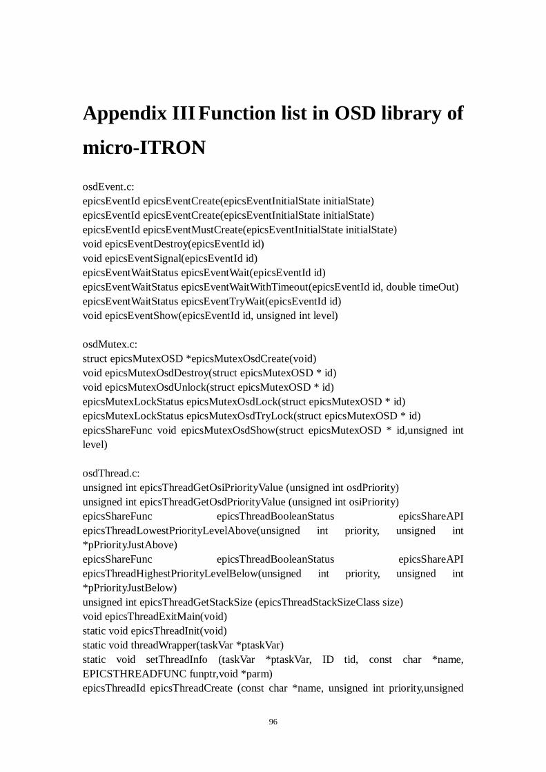
96
Appendix III Function list in OSD library of
micro-ITRON
osdEvent.c: epicsEventId epicsEventCreate(epicsEventInitialState initialState) epicsEventId epicsEventCreate(epicsEventInitialState initialState) epicsEventId epicsEventMustCreate(epicsEventInitialState initialState) void epicsEventDestroy(epicsEventId id) void epicsEventSignal(epicsEventId id) epicsEventWaitStatus epicsEventWait(epicsEventId id) epicsEventWaitStatus epicsEventWaitWithTimeout(epicsEventId id, double timeOut) epicsEventWaitStatus epicsEventTryWait(epicsEventId id) void epicsEventShow(epicsEventId id, unsigned int level) osdMutex.c: struct epicsMutexOSD *epicsMutexOsdCreate(void) void epicsMutexOsdDestroy(struct epicsMutexOSD * id) void epicsMutexOsdUnlock(struct epicsMutexOSD * id) epicsMutexLockStatus epicsMutexOsdLock(struct epicsMutexOSD * id) epicsMutexLockStatus epicsMutexOsdTryLock(struct epicsMutexOSD * id) epicsShareFunc void epicsMutexOsdShow(struct epicsMutexOSD * id,unsigned int level) osdThread.c: unsigned int epicsThreadGetOsiPriorityValue (unsigned int osdPriority) unsigned int epicsThreadGetOsdPriorityValue (unsigned int osiPriority) epicsShareFunc epicsThreadBooleanStatus epicsShareAPI epicsThreadLowestPriorityLevelAbove(unsigned int priority, unsigned int *pPriorityJustAbove) epicsShareFunc epicsThreadBooleanStatus epicsShareAPI epicsThreadHighestPriorityLevelBelow(unsigned int priority, unsigned int *pPriorityJustBelow) unsigned int epicsThreadGetStackSize (epicsThreadStackSizeClass size) void epicsThreadExitMain(void) static void epicsThreadInit(void) static void threadWrapper(taskVar *ptaskVar) static void setThreadInfo (taskVar *ptaskVar, ID tid, const char *name, EPICSTHREADFUNC funptr,void *parm) epicsThreadId epicsThreadCreate (const char *name, unsigned int priority,unsigned
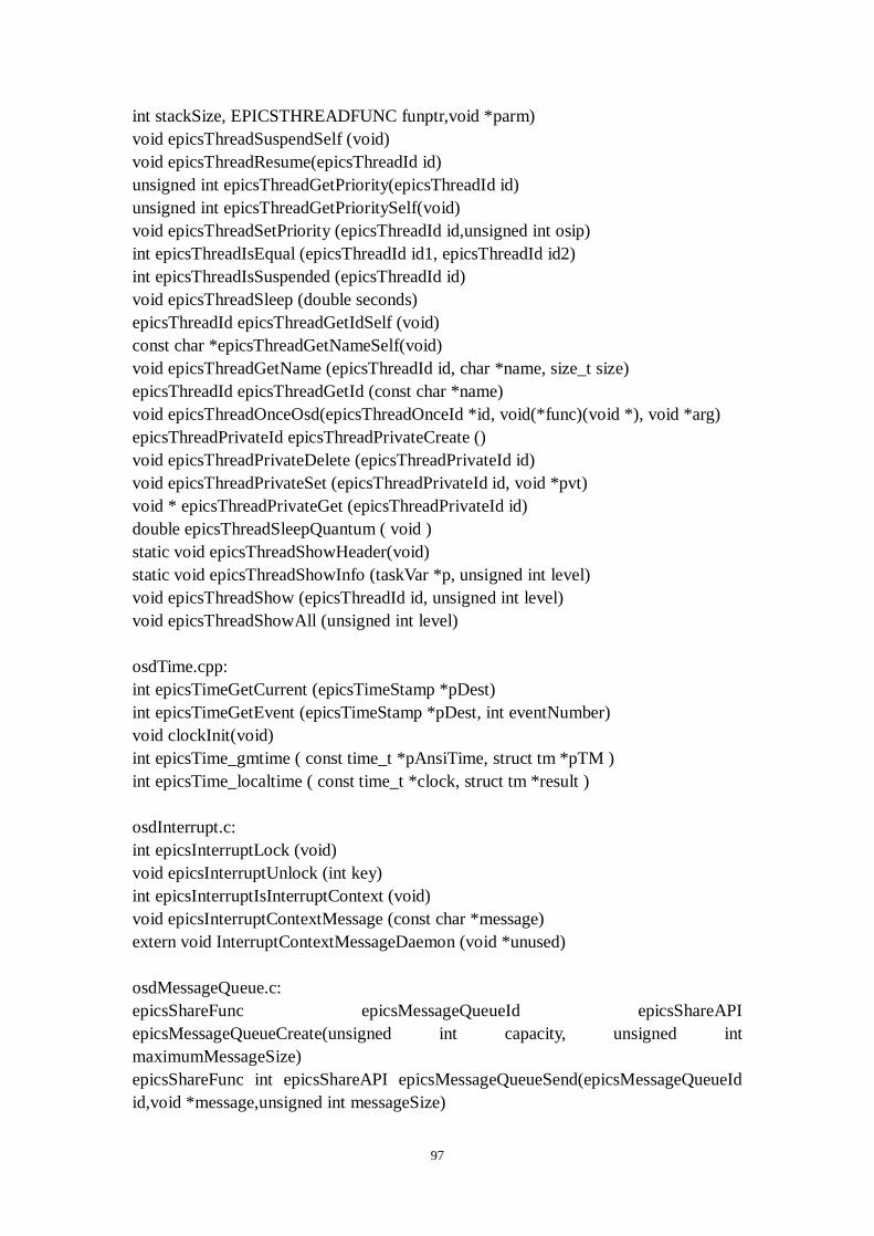
97
int stackSize, EPICSTHREADFUNC funptr,void *parm) void epicsThreadSuspendSelf (void) void epicsThreadResume(epicsThreadId id) unsigned int epicsThreadGetPriority(epicsThreadId id) unsigned int epicsThreadGetPrioritySelf(void) void epicsThreadSetPriority (epicsThreadId id,unsigned int osip) int epicsThreadIsEqual (epicsThreadId id1, epicsThreadId id2) int epicsThreadIsSuspended (epicsThreadId id) void epicsThreadSleep (double seconds) epicsThreadId epicsThreadGetIdSelf (void) const char *epicsThreadGetNameSelf(void) void epicsThreadGetName (epicsThreadId id, char *name, size_t size) epicsThreadId epicsThreadGetId (const char *name) void epicsThreadOnceOsd(epicsThreadOnceId *id, void(*func)(void *), void *arg) epicsThreadPrivateId epicsThreadPrivateCreate () void epicsThreadPrivateDelete (epicsThreadPrivateId id) void epicsThreadPrivateSet (epicsThreadPrivateId id, void *pvt) void * epicsThreadPrivateGet (epicsThreadPrivateId id) double epicsThreadSleepQuantum ( void ) static void epicsThreadShowHeader(void) static void epicsThreadShowInfo (taskVar *p, unsigned int level) void epicsThreadShow (epicsThreadId id, unsigned int level) void epicsThreadShowAll (unsigned int level) osdTime.cpp: int epicsTimeGetCurrent (epicsTimeStamp *pDest) int epicsTimeGetEvent (epicsTimeStamp *pDest, int eventNumber) void clockInit(void) int epicsTime_gmtime ( const time_t *pAnsiTime, struct tm *pTM ) int epicsTime_localtime ( const time_t *clock, struct tm *result ) osdInterrupt.c: int epicsInterruptLock (void) void epicsInterruptUnlock (int key) int epicsInterruptIsInterruptContext (void) void epicsInterruptContextMessage (const char *message) extern void InterruptContextMessageDaemon (void *unused) osdMessageQueue.c: epicsShareFunc epicsMessageQueueId epicsShareAPI epicsMessageQueueCreate(unsigned int capacity, unsigned int maximumMessageSize) epicsShareFunc int epicsShareAPI epicsMessageQueueSend(epicsMessageQueueId id,void *message,unsigned int messageSize)

98
epicsShareFunc int epicsShareAPI epicsMessageQueueTryReceive(epicsMessageQueueId id,void *message,unsigned int size) epicsShareFunc int epicsShareAPI epicsMessageQueueReceive(epicsMessageQueueId id,void *message,unsigned int size) epicsShareFunc int epicsShareAPI epicsMessageQueueReceiveWithTimeout(epicsMessageQueueId id,void *message,unsigned int size,double timeout) epicsShareFunc int epicsShareAPI epicsMessageQueuePending(epicsMessageQueueId id) epicsShareFunc void epicsShareAPI epicsMessageQueueDestroy(epicsMessageQueueId id) epicsShareFunc void epicsShareAPI epicsMessageQueueShow(epicsMessageQueueId id,int level) osdPoolStatus.c: epicsShareFunc int epicsShareAPI osiSufficentSpaceInPool(size_t contiguousBlockSize) osdProcess.c: epicsShareFunc osiGetUserNameReturn epicsShareAPI osiGetUserName (char *pBuf, unsigned bufSizeIn) epicsShareFunc osiSpawnDetachedProcessReturn epicsShareAPI osiSpawnDetachedProcess(const char *pProcessName, const char *pBaseExecutableName) osdSignal.cpp: epicsShareFunc void epicsShareAPI epicsSignalInstallSigPipeIgnore ( void ) {} epicsShareFunc void epicsShareAPI epicsSignalInstallSigAlarmIgnore ( void ) {} epicsShareFunc void epicsShareAPI epicsSignalRaiseSigAlarm ( struct epicsThreadOSD * /* threadId */ ) {} osdNetIntf.c: epicsShareFunc osiSockAddr epicsShareAPI osiLocalAddr( SOCKET socket ) epicsShareFunc void epicsShareAPI osiSockDiscoverBroadcastAddresses(ELLLIST *pList, SOCKET socket, const osiSockAddr *pMatchAddr) osdSock.c: struct hostent *gethostbyaddr(const char *addr,int len,int type) int gethostname(char *hostname, size_t size) epicsShareFunc SOCKET epicsShareAPI epicsSocketCreate(int domain, int type, int protocol) epicsShareFunc int epicsShareAPI epicsSocketAccept(int sock, struct sockaddr *

99
pAddr, osiSocklen_t * addrlen) void osiSockRelease() epicsShareFunc void epicsShareAPI epicsSocketDestroy ( SOCKET s ) int osiSockAttach() epicsShareFunc unsigned epicsShareAPI ipAddrToHostName(const struct in_addr *pAddr, char *pBuf, unsigned bufSize) epicsShareFunc int epicsShareAPI hostToIPAddr(const char *pHostName, struct in_addr *pIPA) 78 functions in total.
100
Appendix IV Function list in Standard C
library
float.h: extern int isnan(double num) extern int isinf(float num) stdio.h: extern FILE *fdopen(int handle, const char * tmp) extern char *tmpnam (char * tmp) extern FILE *tmpfile (void) int vsnprintf(char *str, size_t size, const char *fmt, va_list ap) stdlib.h: extern int atexit (void (*function)(void)) extern void exit(int status) extern void abort(void) extern char *getenv (const char * tmp) extern int putenv (const char * tmp) Time.h: extern int gettimeofday (struct timeval *tv, struct timezone * tz) extern time_t mktime(struct tm *tim_p) size_t strftime(char *s, size_t maxsize, const char *format, const struct tm *tim_p) extern double difftime(time_t time1, time_t time2) struct tm *localtime_r(const time_t *tim_p, struct tm *res) struct tm *gmtime_r(const time_t *tim_p, struct tm *res) 17 functions in total.