Development of Back Propagation Neural Network...
10
International Journal of Advanced Research in Computer Engineering & Technology (IJARCET) Volume 3 Issue 4, April 2014 ISSN: 2278 – 1323 All Rights Reserved © 2014 IJARCET 1229 Development of Back Propagation Neural Network Model for Extracting the Feature from a Image Using Curvelet Transform Mr. Tejas P. Patil 1 , Prof. P. P. Narwade 2 1 PG Student, 2 Profeser EXTC Department, MGM’s collage of Engineering & Technology, Kamothe(Navi mumbai). Image Processing is a technique to enhance raw images received from cameras/sensors placed on satellites, space probes and aircrafts or pictures taken in normal day-today life for various applications. Most of the techniques are developed for enhancing images obtained from unmanned spacecrafts, space probes and military reconnaissance flights. Image Processing systems are becoming popular due to easy availability of powerful personnel computers, large size memory devices, graphics software etc Study of Back Propagation Neural Network algorithm and Curvelet transform algorithm to extract the data from satellite (Segmentation).To implement the Curvelet Transform to extract the Statistical features (mean, standard deviation) that are calculated for each combination of scale and orientation and To extract the features (Land cover, Vegetation, Soil and Water Bodies) of texture Images. Finally, to implement BPNN (Back Propagation Neural Network) algorithm, this provides computationally efficient method for changing the weights. Artificial neural network Back propagation neural network Curvelet-transform Granular neural networks Neural Network Ensemble Segmentation I. INTRODUCTON Image Processing is a technique to enhance raw images received from cameras/sensors placed on satellites, space probes and aircrafts or pictures taken in normal day-today life for various applications. Various techniques have been developed in Image Processing during the last four to five decades[1],[10]. Most of the techniques are developed for enhancing images obtained from unmanned spacecrafts, space probes and military reconnaissance flights. Image Processing systems are becoming popular due to easy availability of powerful personnel computers, large size memory devices, graphics software etc[1]. In Neural Networks is a field of Artificial Intelligence (AI) it is inspired rom the human brain, find data structures and algorithms for learning and classification of data. Many tasks that humans perform naturally fast, such as the recognition of a familiar face, to be a very complicated task for a computer when conventional programming methods are used[1],[11]. By applying Neural Network techniques a program can learn by examples, and create an internal structure of rules to classify different inputs, such as recognizing images. II. ARTIFICIAL NEURAL NETWORKS Artificial Neural Networks are commonly used in pattern classification, function approximation, optimization, pattern matching, machine learning and associative memories. They are currently being an alternative to traditional statistical methods for mining data sets in order to classify data. Artificial Neural Networks are well-established technology for solving prediction and classification problems, using training and testing data to build a model[1][4]. However, the success of the networks is highly dependent on the performance of the training process. ABSTRACT Keywords
Transcript of Development of Back Propagation Neural Network...
International Journal of Advanced Research in Computer Engineering & Technology (IJARCET)
Volume 3 Issue 4, April 2014
ISSN: 2278 – 1323 All Rights Reserved © 2014 IJARCET 1229
Development of Back Propagation Neural Network Model for Extracting the
Feature from a Image Using Curvelet Transform
Mr. Tejas P. Patil1, Prof. P. P. Narwade
2
1PG Student, 2Profeser EXTC Department, MGM’s collage of Engineering & Technology, Kamothe(Navi mumbai).
Image Processing is a technique to enhance raw images received from
cameras/sensors placed on satellites, space probes and aircrafts or pictures taken in
normal day-today life for various applications. Most of the techniques are developed
for enhancing images obtained from unmanned spacecrafts, space probes and military
reconnaissance flights. Image Processing systems are becoming popular due to easy
availability of powerful personnel computers, large size memory devices, graphics
software etc Study of Back Propagation Neural Network algorithm and Curvelet
transform algorithm to extract the data from satellite (Segmentation).To implement the
Curvelet Transform to extract the Statistical features (mean, standard deviation) that
are calculated for each combination of scale and orientation and To extract the
features (Land cover, Vegetation, Soil and Water Bodies) of texture Images. Finally, to
implement BPNN (Back Propagation Neural Network) algorithm, this provides
computationally efficient method for changing the weights.
Artificial neural network
Back propagation neural
network
Curvelet-transform
Granular neural
networks
Neural Network Ensemble
Segmentation
I. INTRODUCTON
Image Processing is a technique to enhance raw
images received from cameras/sensors placed on
satellites, space probes and aircrafts or pictures taken in
normal day-today life for various applications. Various
techniques have been developed in Image Processing
during the last four to five decades[1],[10]. Most of the
techniques are developed for enhancing images obtained
from unmanned spacecrafts, space probes and military
reconnaissance flights. Image Processing systems are
becoming popular due to easy availability of powerful
personnel computers, large size memory devices,
graphics software etc[1]. In Neural Networks is a field
of Artificial Intelligence (AI) it is inspired rom the
human brain, find data structures and algorithms for
learning and classification of data.
Many tasks that humans perform naturally fast,
such as the recognition of a familiar face, to be a very
complicated task for a computer when conventional
programming methods are used[1],[11]. By applying
Neural Network techniques a program can learn by
examples, and create an internal structure of rules to
classify different inputs, such as recognizing images.
II. ARTIFICIAL NEURAL NETWORKS
Artificial Neural Networks are commonly used in
pattern classification, function approximation,
optimization, pattern matching, machine learning and
associative memories. They are currently being an
alternative to traditional statistical methods for mining
data sets in order to classify data. Artificial Neural
Networks are well-established technology for solving
prediction and classification problems, using training
and testing data to build a model[1][4]. However, the
success of the networks is highly dependent on the
performance of the training process.
ABSTRACT Keywords
A B S T R A C T
International Journal of Advanced Research in Computer Engineering & Technology (IJARCET)
Volume 3 Issue 4, April 2014
ISSN: 2278 – 1323 All Rights Reserved © 2014 IJARCET 1230
Broad applicable areas of artificial neural networks,
pattern recognition is one of the most important
applications in such problems: speech synthesis,
diagnostic problems, medicine, finance, robotic control,
signal processing, computer vision and many other
problems that fall under the category of pattern
recognition. Among many different neural network
classifiers, the multilayer feed- forward networks have
been mainly used for solving classification tasks, due to
their well-known universal approximation capabilities.
The success of neural networks largely depends on their
architecture, their training algorithm, and the choice of
features used in training.
Artificial neural networks (ANN) are very
important tools for solving different kind of problems
such as pattern classification, forecasting and
regression[1]-[4]. However, their design imply a
mechanism of error-testing that tests different
architectures, transfer functions and the selection of a
training algorithm that permits to adjust the synaptic
weights of the ANN. This design is very important
because the wrong selection of one of these
characteristics could provoke that the training algorithm
be trapped in a local minimum. Because of this, several
met heuristic based methods in order to obtain a good
ANN design have been reported.
Neural Networks mimic the pattern of human
learning to solve many difficult tasks in the field of
applications which include nonlinear regression,
classification, pattern recognition and control systems
.By configuring virtual neural networks that function
like the human brain, computers can perform tasks at
greater speeds and with increased flexibility of
application. These networks are capable of offering
invaluable insights into the vast information stockpiles
that are common today. The artificial networks simulate
the complex neural network by clustering the artificial
neurons. In every neuron system, there must be some
input nodes as well as some output nodes. Some of the
neurons interface the real world to receive the inputs
and some other neurons provide the real world with the
outputs of the network. The rest of the neurons are
hidden layers whose number depends on the problem to
be solved.
2.1 Artificial Neural Network (ANN) Model[4]
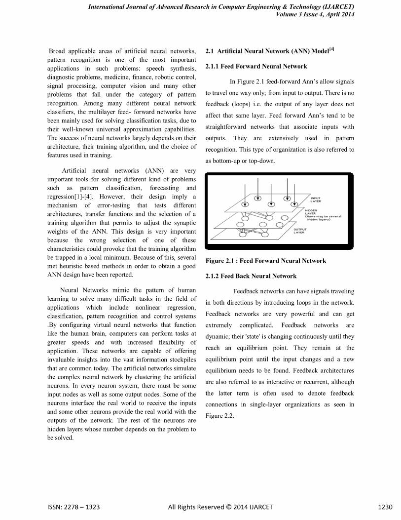
2.1.1 Feed Forward Neural Network
In Figure 2.1 feed-forward Ann’s allow signals
to travel one way only; from input to output. There is no
feedback (loops) i.e. the output of any layer does not
affect that same layer. Feed forward Ann’s tend to be
straightforward networks that associate inputs with
outputs. They are extensively used in pattern
recognition. This type of organization is also referred to
as bottom-up or top-down.
Figure 2.1 : Feed Forward Neural Network
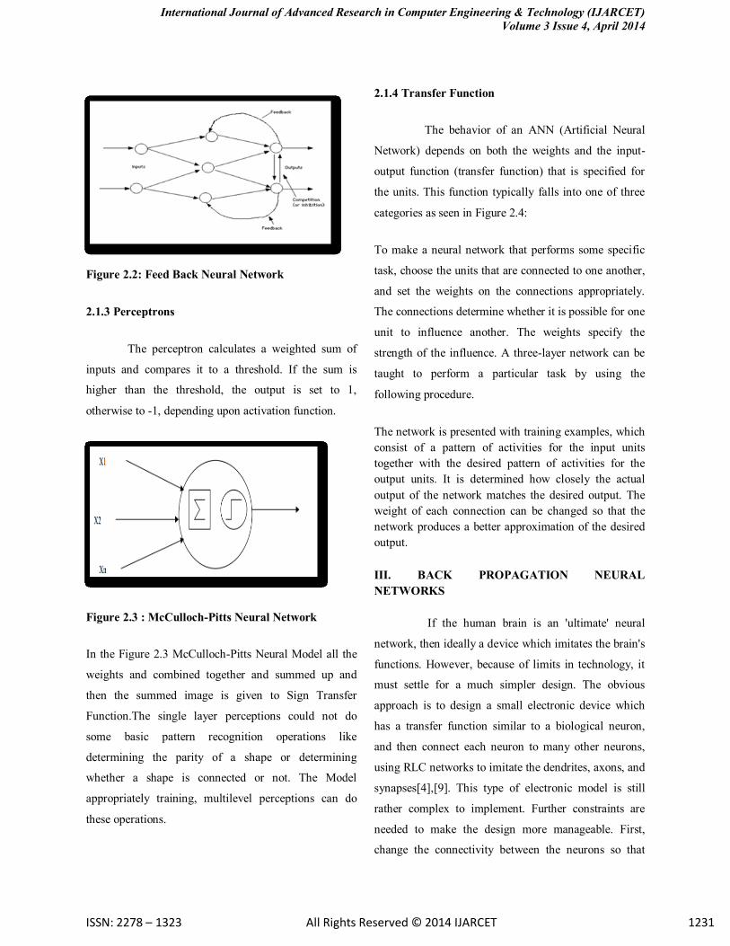
2.1.2 Feed Back Neural Network
Feedback networks can have signals traveling
in both directions by introducing loops in the network.
Feedback networks are very powerful and can get
extremely complicated. Feedback networks are
dynamic; their 'state' is changing continuously until they
reach an equilibrium point. They remain at the
equilibrium point until the input changes and a new
equilibrium needs to be found. Feedback architectures
are also referred to as interactive or recurrent, although
the latter term is often used to denote feedback
connections in single-layer organizations as seen in
Figure 2.2.
International Journal of Advanced Research in Computer Engineering & Technology (IJARCET)
Volume 3 Issue 4, April 2014
ISSN: 2278 – 1323 All Rights Reserved © 2014 IJARCET 1231
Figure 2.2: Feed Back Neural Network
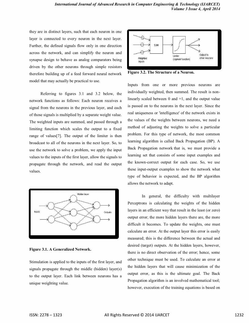
2.1.3 Perceptrons
The perceptron calculates a weighted sum of
inputs and compares it to a threshold. If the sum is
higher than the threshold, the output is set to 1,
otherwise to -1, depending upon activation function.
Figure 2.3 : McCulloch-Pitts Neural Network
In the Figure 2.3 McCulloch-Pitts Neural Model all the
weights and combined together and summed up and
then the summed image is given to Sign Transfer
Function.The single layer perceptions could not do
some basic pattern recognition operations like
determining the parity of a shape or determining
whether a shape is connected or not. The Model
appropriately training, multilevel perceptions can do
these operations.
2.1.4 Transfer Function
The behavior of an ANN (Artificial Neural
Network) depends on both the weights and the input-
output function (transfer function) that is specified for
the units. This function typically falls into one of three
categories as seen in Figure 2.4:
To make a neural network that performs some specific
task, choose the units that are connected to one another,
and set the weights on the connections appropriately.
The connections determine whether it is possible for one
unit to influence another. The weights specify the
strength of the influence. A three-layer network can be
taught to perform a particular task by using the
following procedure.
The network is presented with training examples, which
consist of a pattern of activities for the input units
together with the desired pattern of activities for the
output units. It is determined how closely the actual
output of the network matches the desired output. The
weight of each connection can be changed so that the
network produces a better approximation of the desired
output.
III. BACK PROPAGATION NEURAL
NETWORKS
If the human brain is an 'ultimate' neural
network, then ideally a device which imitates the brain's
functions. However, because of limits in technology, it
must settle for a much simpler design. The obvious
approach is to design a small electronic device which
has a transfer function similar to a biological neuron,
and then connect each neuron to many other neurons,
using RLC networks to imitate the dendrites, axons, and
synapses[4],[9]. This type of electronic model is still
rather complex to implement. Further constraints are
needed to make the design more manageable. First,
change the connectivity between the neurons so that
International Journal of Advanced Research in Computer Engineering & Technology (IJARCET)
Volume 3 Issue 4, April 2014
ISSN: 2278 – 1323 All Rights Reserved © 2014 IJARCET 1232
they are in distinct layers, such that each neuron in one
layer is connected to every neuron in the next layer.
Further, the defined signals flow only in one direction
across the network, and can simplify the neuron and
synapse design to behave as analog comparators being
driven by the other neurons through simple resistors
therefore building up of a feed forward neural network
model that may actually be practical to use.
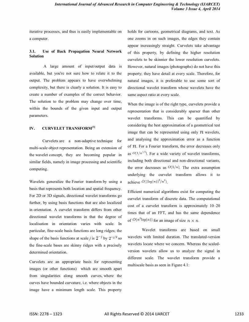
Referring to figures 3.1 and 3.2 below, the
network functions as follows: Each neuron receives a
signal from the neurons in the previous layer, and each
of those signals is multiplied by a separate weight value.
The weighted inputs are summed, and passed through a
limiting function which scales the output to a fixed
range of values[7]. The output of the limiter is then
broadcast to all of the neurons in the next layer. So, to
use the network to solve a problem, we apply the input
values to the inputs of the first layer, allow the signals to
propagate through the network, and read the output
values.
Figure 3.1. A Generalized Network.
Stimulation is applied to the inputs of the first layer, and
signals propagate through the middle (hidden) layer(s)
to the output layer. Each link between neurons has a
unique weighting value.
Figure 3.2. The Structure of a Neuron.
Inputs from one or more previous neurons are
individually weighted, then summed. The result is non-
linearly scaled between 0 and +1, and the output value
is passed on to the neurons in the next layer. Since the
real uniqueness or 'intelligence' of the network exists in
the values of the weights between neurons, we need a
method of adjusting the weights to solve a particular
problem. For this type of network, the most common
learning algorithm is called Back Propagation (BP). A
Back Propagation network that is, we must provide a
learning set that consists of some input examples and
the known-correct output for each case. So, we use
these input-output examples to show the network what
type of behavior is expected, and the BP algorithm
allows the network to adapt.
In general, the difficulty with multilayer
Perceptrons is calculating the weights of the hidden
layers in an efficient way that result in the least (or zero)
output error; the more hidden layers there are, the more
difficult it becomes. To update the weights, one must
calculate an error. At the output layer this error is easily
measured; this is the difference between the actual and
desired (target) outputs. At the hidden layers, however,
there is no direct observation of the error; hence, some
other technique must be used. To calculate an error at
the hidden layers that will cause minimization of the
output error, as this is the ultimate goal. The Back
Propagation algorithm is an involved mathematical tool;
however, execution of the training equations is based on
International Journal of Advanced Research in Computer Engineering & Technology (IJARCET)
Volume 3 Issue 4, April 2014
ISSN: 2278 – 1323 All Rights Reserved © 2014 IJARCET 1233
iterative processes, and thus is easily implementable on
a computer.
3.1. Use of Back Propagation Neural Network
Solution
A large amount of input/output data is
available, but you're not sure how to relate it to the
output. The problem appears to have overwhelming
complexity, but there is clearly a solution. It is easy to
create a number of examples of the correct behavior.
The solution to the problem may change over time,
within the bounds of the given input and output
parameters.
IV. CURVELET TRANSFORM[3]
Curvelets are a non-adaptive technique for
multi-scale object representation. Being an extension of
the wavelet concept, they are becoming popular in
similar fields, namely in image processing and scientific
computing.
Wavelets generalize the Fourier transform by using a
basis that represents both location and spatial frequency.
For 2D or 3D signals, directional wavelet transforms go
further, by using basis functions that are also localized
in orientation. A curvelet transform differs from other
directional wavelet transforms in that the degree of
localisation in orientation varies with scale. In
particular, fine-scale basis functions are long ridges; the
shape of the basis functions at scale j is by so
the fine-scale bases are skinny ridges with a precisely
determined orientation.
Curvelets are an appropriate basis for representing
images (or other functions) which are smooth apart
from singularities along smooth curves, where the
curves have bounded curvature, i.e. where objects in the
image have a minimum length scale. This property
holds for cartoons, geometrical diagrams, and text. As
one zooms in on such images, the edges they contain
appear increasingly straight. Curvelets take advantage
of this property, by defining the higher resolution
curvelets to be skinnier the lower resolution curvelets.
However, natural images (photographs) do not have this
property; they have detail at every scale. Therefore, for
natural images, it is preferable to use some sort of
directional wavelet transform whose wavelets have the
same aspect ratio at every scale.
When the image is of the right type, curvelets provide a
representation that is considerably sparser than other
wavelet transforms. This can be quantified by
considering the best approximation of a geometrical test
image that can be represented using only wavelets,
and analysing the approximation error as a function
of . For a Fourier transform, the error decreases only
as . For a wide variety of wavelet transforms,
including both directional and non-directional variants,
the error decreases as . The extra assumption
underlying the curvelet transform allows it to
achieve .
Efficient numerical algorithms exist for computing the
curvelet transform of discrete data. The computational
cost of a curvelet transform is approximately 10–20
times that of an FFT, and has the same dependence
of for an image of size .
Wavelet transforms are based on small
wavelets with limited duration. The translated-version
wavelets locate where we concern. Whereas the scaled-
version wavelets allow us to analyze the signal in
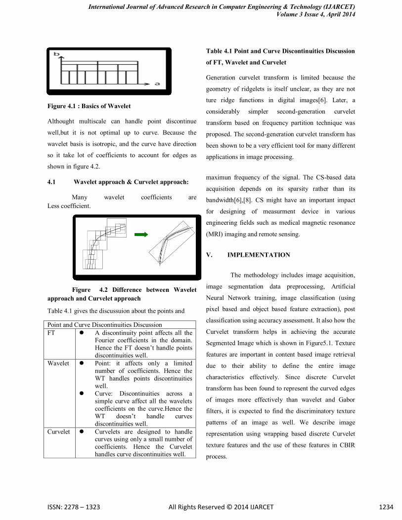
different scale. The wavelet transform provide a
multiscale basis as seen in Figure 4.1:
International Journal of Advanced Research in Computer Engineering & Technology (IJARCET)
Volume 3 Issue 4, April 2014
ISSN: 2278 – 1323 All Rights Reserved © 2014 IJARCET 1234
Figure 4.1 : Basics of Wavelet
Althought multiscale can handle point discontinue
well,but it is not optimal up to curve. Because the
wavelet basis is isotropic, and the curve have direction
so it take lot of coefficients to account for edges as
shown in figure 4.2.
4.1 Wavelet approach & Curvelet approach:
Many wavelet coefficients are
Less coefficient.
Figure 4.2 Difference between Wavelet
approach and Curvelet approach
Table 4.1 gives the discussuion about the points and
Table 4.1 Point and Curve Discontinuities Discussion
of FT, Wavelet and Curvelet
Generation curvelet transform is limited because the
geometry of ridgelets is itself unclear, as they are not
ture ridge functions in digital images[6]. Later, a
considerably simpler second-generation curvelet
transform based on frequency partition technique was
proposed. The second-generation curvelet transform has
been shown to be a very efficient tool for many different
applications in image processing.
maximun frequency of the signal. The CS-based data
acquisition depends on its sparsity rather than its
bandwidth[6],[8]. CS might have an important impact
for designing of measurment device in various
engineering fields such as medical magnetic resonance
(MRI) imaging and remote sensing.
V. IMPLEMENTATION
The methodology includes image acquisition,
image segmentation data preprocessing, Artificial
Neural Network training, image classification (using
pixel based and object based feature extraction), post
classification using accuracy assessment. It also how the
Curvelet transform helps in achieving the accurate
Segmented Image which is shown in Figure5.1. Texture
features are important in content based image retrieval
due to their ability to define the entire image
characteristics effectively. Since discrete Curvelet
transform has been found to represent the curved edges
of images more effectively than wavelet and Gabor
filters, it is expected to find the discriminatory texture
patterns of an image as well. We describe image
representation using wrapping based discrete Curvelet
texture features and the use of these features in CBIR
process.
Point and Curve Discontinuities Discussion
FT A discontinuity point affects all the Fourier coefficients in the domain.
Hence the FT doesn’t handle points
discontinuities well.
Wavelet Point: it affects only a limited
number of coefficients. Hence the
WT handles points discontinuities
well.
Curve: Discontinuities across a
simple curve affect all the wavelets
coefficients on the curve.Hence the
WT doesn’t handle curves
discontinuities well.
Curvelet Curvelets are designed to handle curves using only a small number of
coefficients. Hence the Curvelet
handles curve discontinuities well.
International Journal of Advanced Research in Computer Engineering & Technology (IJARCET)
Volume 3 Issue 4, April 2014
ISSN: 2278 – 1323 All Rights Reserved © 2014 IJARCET 1235
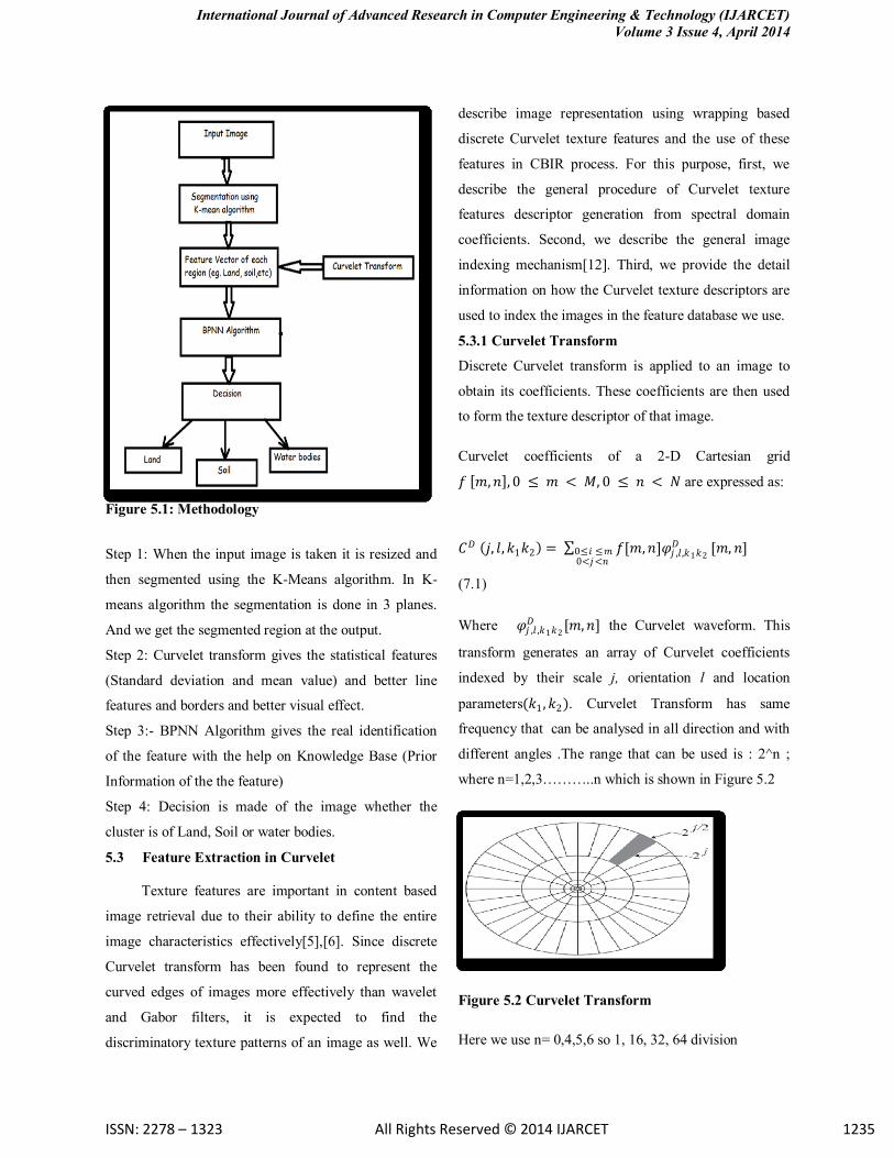
Figure 5.1: Methodology
Step 1: When the input image is taken it is resized and
then segmented using the K-Means algorithm. In K-
means algorithm the segmentation is done in 3 planes.
And we get the segmented region at the output.
Step 2: Curvelet transform gives the statistical features
(Standard deviation and mean value) and better line
features and borders and better visual effect.
Step 3:- BPNN Algorithm gives the real identification
of the feature with the help on Knowledge Base (Prior
Information of the the feature)
Step 4: Decision is made of the image whether the
cluster is of Land, Soil or water bodies.
5.3 Feature Extraction in Curvelet
Texture features are important in content based
image retrieval due to their ability to define the entire
image characteristics effectively[5],[6]. Since discrete
Curvelet transform has been found to represent the
curved edges of images more effectively than wavelet
and Gabor filters, it is expected to find the
discriminatory texture patterns of an image as well. We
describe image representation using wrapping based
discrete Curvelet texture features and the use of these
features in CBIR process. For this purpose, first, we
describe the general procedure of Curvelet texture
features descriptor generation from spectral domain
coefficients. Second, we describe the general image
indexing mechanism[12]. Third, we provide the detail
information on how the Curvelet texture descriptors are
used to index the images in the feature database we use.
5.3.1 Curvelet Transform
Discrete Curvelet transform is applied to an image to
obtain its coefficients. These coefficients are then used
to form the texture descriptor of that image.
Curvelet coefficients of a 2-D Cartesian grid
𝑓 𝑚, 𝑛 , 0 ≤ 𝑚 < 𝑀, 0 ≤ 𝑛 < 𝑁 are expressed as:
𝐶𝐷 𝑗, 𝑙, 𝑘1𝑘2 = 𝑓[𝑚, 𝑛]𝜑𝑗 ,𝑙 ,𝑘1𝑘2
𝐷0≤ 𝑖 ≤ 𝑚0<𝑗<𝑛
[𝑚, 𝑛]
(7.1)
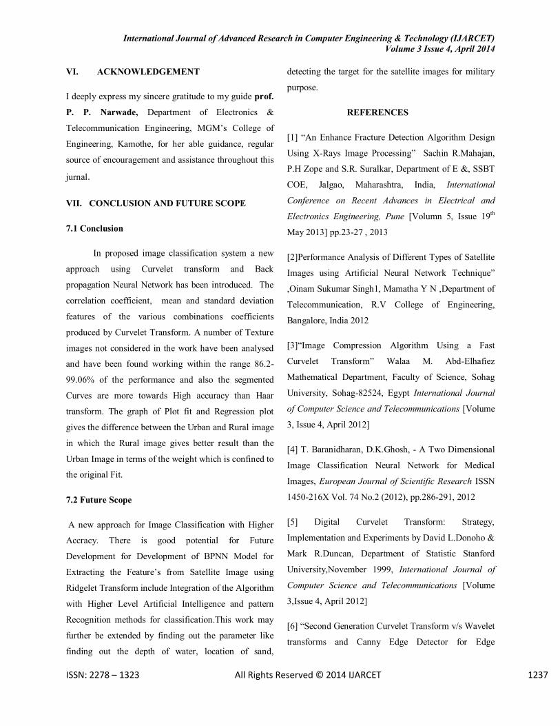
Where 𝜑𝑗 ,𝑙 ,𝑘1𝑘2
𝐷 [𝑚, 𝑛] the Curvelet waveform. This
transform generates an array of Curvelet coefficients
indexed by their scale j, orientation l and location
parameters(𝑘1 , 𝑘2). Curvelet Transform has same
frequency that can be analysed in all direction and with
different angles .The range that can be used is : 2^n ;
where n=1,2,3………..n which is shown in Figure 5.2
Figure 5.2 Curvelet Transform
Here we use n= 0,4,5,6 so 1, 16, 32, 64 division

International Journal of Advanced Research in Computer Engineering & Technology (IJARCET)
Volume 3 Issue 4, April 2014
ISSN: 2278 – 1323 All Rights Reserved © 2014 IJARCET 1236
5.4 Curvelet Algorithm
[1] First 2D Fast Fourier Transform (FFT) of the image
is taken.
[2] 2D Fourier frequency plane is divided into wedges.
[3] The concentric circles decompose an image into
multiple scales (used for band passing the image at
different scale) and the angular divisions partition into
different angles or orientations.
[4] For particular wedge we need to define its scale and
angle.Discrete Curvelet transform is implemented using
the wrapping based fast discrete Curvelet transform.
Basically, Multiresolution discrete Curvelet transform in
the spectral domain utilizes the advantages of fast
Fourier transform (FFT). During FFT, both the image
and the Curvelet at a given scale and orientation are
transformed into the Fourier domain. The convolution
of the Curvelet with the image in the spatial domain
then becomes their product in the Fourier
domain[5],[6],[8]. At the end of this computation
process, a set of Curvelet coefficients by applying
inverse FFT to the spectral product. This set contains
Curvelet coefficients in ascending order of the scales
and orientations the complete feature extraction process
using one single Curvelet is illustrated in Fig. 5.3(a).The
wrapping is illustrated in Fig. 5.3(b) and explained as
following. As shown in Fig. 5.3(b), in order to do IFFT
on the FT wedge, the wedge has to be arranged as a
rectangle. The idea is to replicate the wedge on a 2-grid,
so a rectangle in the center captures all the components
a, b, and c of the wedge.
Figure 5.3 : Fast Discrete Curvelet Transform to
Generate Curvelet Coefficient
Wedge wrapping is done for all the wedges at each scale
in the frequency domain, so we obtain a set of sub bands
or wedges at each Curvelet decomposition level. These
sub bands are the collection of discrete Curvelet
coefficients.To provide an illustration of Curvelet sub
bands, we apply fast discrete Curvelet transform to a
512×512 Lena image with 6 decomposition levels using
Curvelab-2.1.2 of. The sub bands generated from this
image are shown in Fig. 5.4. Lena image has a rich
collection of multidirectional edges. From all the sub
band images of Lena image shown in Fig. 5.4, we find
that the wrapping based discrete Curvelet coefficients
capture and represent the edge information more
accurately.
a)curvelet subband at scale 6
(b)First 32 Sub bands (Left contains first 16, right
contains last 16 sub bands)
International Journal of Advanced Research in Computer Engineering & Technology (IJARCET)
Volume 3 Issue 4, April 2014
ISSN: 2278 – 1323 All Rights Reserved © 2014 IJARCET 1237
VI. ACKNOWLEDGEMENT
I deeply express my sincere gratitude to my guide prof.
P. P. Narwade, Department of Electronics &
Telecommunication Engineering, MGM’s College of
Engineering, Kamothe, for her able guidance, regular
source of encouragement and assistance throughout this
jurnal.
VII. CONCLUSION AND FUTURE SCOPE
7.1 Conclusion
In proposed image classification system a new
approach using Curvelet transform and Back
propagation Neural Network has been introduced. The
correlation coefficient, mean and standard deviation
features of the various combinations coefficients
produced by Curvelet Transform. A number of Texture
images not considered in the work have been analysed
and have been found working within the range 86.2-
99.06% of the performance and also the segmented
Curves are more towards High accuracy than Haar
transform. The graph of Plot fit and Regression plot
gives the difference between the Urban and Rural image
in which the Rural image gives better result than the
Urban Image in terms of the weight which is confined to
the original Fit.
7.2 Future Scope
A new approach for Image Classification with Higher
Accracy. There is good potential for Future
Development for Development of BPNN Model for
Extracting the Feature’s from Satellite Image using
Ridgelet Transform include Integration of the Algorithm
with Higher Level Artificial Intelligence and pattern
Recognition methods for classification.This work may
further be extended by finding out the parameter like
finding out the depth of water, location of sand,
detecting the target for the satellite images for military
purpose.
REFERENCES
[1] “An Enhance Fracture Detection Algorithm Design
Using X-Rays Image Processing” Sachin R.Mahajan,
P.H Zope and S.R. Suralkar, Department of E &, SSBT
COE, Jalgao, Maharashtra, India, International
Conference on Recent Advances in Electrical and
Electronics Engineering, Pune [Volumn 5, Issue 19th
May 2013] pp.23-27 , 2013
[2]Performance Analysis of Different Types of Satellite
Images using Artificial Neural Network Technique”
,Oinam Sukumar Singh1, Mamatha Y N ,Department of
Telecommunication, R.V College of Engineering,
Bangalore, India 2012
[3]“Image Compression Algorithm Using a Fast
Curvelet Transform” Walaa M. Abd-Elhafiez
Mathematical Department, Faculty of Science, Sohag
University, Sohag-82524, Egypt International Journal
of Computer Science and Telecommunications [Volume
3, Issue 4, April 2012]
[4] T. Baranidharan, D.K.Ghosh, - A Two Dimensional
Image Classification Neural Network for Medical
Images, European Journal of Scientific Research ISSN
1450-216X Vol. 74 No.2 (2012), pp.286-291, 2012
[5] Digital Curvelet Transform: Strategy,
Implementation and Experiments by David L.Donoho &
Mark R.Duncan, Department of Statistic Stanford
University,November 1999, International Journal of
Computer Science and Telecommunications [Volume
3,Issue 4, April 2012]
[6] “Second Generation Curvelet Transform v/s Wavelet
transforms and Canny Edge Detector for Edge

International Journal of Advanced Research in Computer Engineering & Technology (IJARCET)
Volume 3 Issue 4, April 2014
ISSN: 2278 – 1323 All Rights Reserved © 2014 IJARCET 1238
Detection ” from World view-2 data Mohamed
Elhabiby a,b, Ahmed Elsharkawy a,c & Naser El-
Sheimy, International journal of Computer Science &
Engineering Survey (IJCSES) Vol.3 ,No. 4, August
2012.
[7] Vincent Cheung, Kevin Cannons “An Introduction
to Neural Networks Signal & Data Compression
Laboratory” Electrical & Computer Engineering
University of Manitoba Winnipeg, Manitoba, Canada
Advisor: Dr. W. Kinsner presentation on May 2012
[8]“NEURO FUZZY MODEL FOR FACE
RECOGNITION WITH CURVELET BASED
FEATURE IMAGE” Shreeja Khushali deulkar, Shalini
Bhatia DJSCOE, Computer Engineering Department,
Mumbai University, Shreeja R et al. / International
Journal of Engineering Science and Technology (IJEST)
ISSN : 0975-5462 Vol. 3 No. 6 June 2011 5306
[9] Virendra P. Vishwakarma, M.N. Gupta, - A New
Learning Algorithm for Single Hidden Layer Feed
forward Neural Network, International Journal of
Computer Application (0975-8887), Volume 28- No.6,
pp 26-33, August 2011
[10]Bin Zou, Huijun Li and Lamei Zhang,- polsar image
classification using bp neural based on Quantum clonal
evolutionary algorithm, IEEE pp.1573-1576,2010
[11] “ Image Segmentation Using the k-means
Algorithm for Texture Features” WanTing Lin, Chuen-
Horng Lin, Tsung-Ho Wu, and Yung-Kuan Chan,
World Academy of Science, Engineering and
Technology 41 2010.
[12] Mehdi Lotfi, Ali Solimani, Aras Dargazany,
Hooman Afzal, Mojtaba Bandarabadi, Combining
Wavelet Transforms and Neural Networks for Image
Classification, IEEE,pp.44-48,2009.