Development of an Adaptive Polarization- Mode … of an Adaptive Polarization-Mode Dispersion...
33
Development of an Adaptive Polarization Development of an Adaptive Polarization - - Mode Dispersion Compensation System Mode Dispersion Compensation System Master Master’ s Thesis Defense s Thesis Defense by by Arun Arun- Prasad Chimata Prasad Chimata Advisor: Dr. Christopher Allen Advisor: Dr. Christopher Allen Dr. Kenneth Demarest Dr. Kenneth Demarest Dr. Dr. Rongqing Hui Rongqing Hui Department of Electrical Engineering and Computer Science Department of Electrical Engineering and Computer Science University of Kansas University of Kansas December 17, 2002 December 17, 2002 1 of 33
Transcript of Development of an Adaptive Polarization- Mode … of an Adaptive Polarization-Mode Dispersion...

Development of an Adaptive PolarizationDevelopment of an Adaptive Polarization--Mode Dispersion Compensation SystemMode Dispersion Compensation System
MasterMaster’’ s Thesis Defenses Thesis Defense
by by
ArunArun--Prasad ChimataPrasad Chimata
Advisor: Dr. Christopher Allen Advisor: Dr. Christopher Allen
Dr. Kenneth Demarest Dr. Kenneth Demarest Dr. Dr. Rongqing HuiRongqing Hui
Department of Electrical Engineering and Computer Science Department of Electrical Engineering and Computer Science
University of KansasUniversity of Kansas
December 17, 2002December 17, 2002
1 of 33

OutlineOutline
•• Motivation Motivation
•• Introduction to PolarizationIntroduction to Polarization--Mode Dispersion (PMD)Mode Dispersion (PMD)
•• Overview of PMD Mitigation ApproachesOverview of PMD Mitigation Approaches
•• Adaptive PMD Compensation System Developed in KUAdaptive PMD Compensation System Developed in KU
•• Experiments, Inferences and Field TrialExperiments, Inferences and Field Trial
•• Summary and ConclusionsSummary and Conclusions
•• Scope for Future Work Scope for Future Work
2 of 33

MotivationMotivation
• Fiber-optic technologies have enabledtoday’s high-speed telecommunicationcapabilities
• Many hurdles crossed (e.g., attenuation,chromatic dispersion)
• Specialized fiber manufacturing methodsevolved to reduce fiber deformities
• Still, at some bit-rate-distance product,system capabilities will be limited byPMD
• Compensation for effects of PMD is asolution Growth of fiberGrowth of fiber--optic system capabilities optic system capabilities
since 1974since 1974
3 of 33

Introduction to PMDIntroduction to PMD
Origins of PMDOrigins of PMD• Single-mode fiber actually has two modes forlight propagation due to asymmetry of corecross-section
• External stresses and inherent deformitiescause asymmetry
• Propagation constants along the two modesare different: birefringence
• Components of an optical signal travelingalong the two modes are differentiallydelayed at output. This delay is calledDifferential Group Delay (DGD)
• An input optical pulse arrives broadened atoutput: this effect is commonly called PMD
DGD (DGD (!"!")) in a short fiber segmentin a short fiber segment
Fiber crossFiber cross--sectionsection
4 of 33

Introduction to PMDIntroduction to PMDPMD in lengthy fiber spans: Pr incipalPMD in lengthy fiber spans: Pr incipalStates modelStates model•Lengthy fiber spans (telecom grade) experiencerandom stresses along the length causing mode-coupling. PMD effect is unpredictable.
•Principal states model proposed to model PMD inlengthy fiber spans
•Every fiber has a set of two orthogonal polarizationstates called Principal States of Polarization (PSPs)that yield an unchanged pulse shape at output.
•Valid for a small frequency range only (i.e. PSPschange with optical frequency). PSPs vary withlength and with time also.
• PMD vector has DGD as magnitude and PSPorientation as direction
ModeMode--couplingcoupling
ModeMode--coupling model of lengthy fiber spancoupling model of lengthy fiber span
Evolution of Evolution of PSPs PSPs along length of a fiber spanalong length of a fiber spanp̂τ τ= ∆�
5 of 33

Introduction to PMDIntroduction to PMDEffects of PMDEffects of PMD
• PMD causes ISI in digital fiber-optic
systems and distortion in analog lightwave
systems
• PMD-induced power penalty, # (dB) in digital
systems is:
A : pulse-shape dependent constant
$ : ratio of power-splitting between the two modes
(0<= $ <= 1)
!" : DGD (ps)
T : FWHM of lightwave pulse (bit-rate dependent)
DGD = 0DGD = 0 psps
DGD = 30 DGD = 30 psps
DGD = 50 DGD = 50 psps
Data rate=10 Data rate=10 GbGb/s /s
2
2
(1 )A
T
τ γ γε ∆ −≅
6 of 33

Introduction to PMDIntroduction to PMD
• DGD follows a Maxwellian
probability distribution (over time and
over wavelength)
• Higher order PMD caused due to
frequency dependence of DGD and
PSPs
• Higher order PMD effects require
consideration as bandwidth increases
(e.g., 40 Gb/s data rate and beyond) and also in WDM systems
PMD statistics and higher order PMDPMD statistics and higher order PMD
Measured DGD distribution in 10 km of spooled Measured DGD distribution in 10 km of spooled fiber (subjected to temperature changes) and the fiber (subjected to temperature changes) and the MaxwellianMaxwellian fitfit Measured DGD of a 14.7 Measured DGD of a 14.7 ps ps mean mean
DGD fiber, over wavelengthDGD fiber, over wavelength7 of 33

Overview of PMD MitigationOverview of PMD Mitigation
PMD monitoring techniquesPMD monitoring techniques
1) RF power levels of specific tones in the received base-band spectrum
2) Degree of polarization (DOP) of the received optical signal
3) Received signal bit-error-rate (BER) or eye-diagram analysis
Overview of PMD compensation techniquesOverview of PMD compensation techniques
Simulated DOP Simulated DOP vs vs $$, the ratio of power splitting , the ratio of power splitting between the two between the two PSPsPSPs, for different DGD values , for different DGD values (NRZ modulation, 10 (NRZ modulation, 10 GbGb/s data rate) /s data rate)
8 of 33
2
2
(1 )A
T
τ γ γε ∆ −≅
PMD-induced power penalty
Overview of PMD MitigationOverview of PMD MitigationComponents in a PMD compensation Components in a PMD compensation system:system:• Polarization controller (PC)• Delay element (variable or fixed)
PMD compensation schemes:PMD compensation schemes:•Half-order PMD compensator.Consists of a PC and a fixed delay element
•First-order PMD compensator. Consists of a PC and a variable delayelement
•Second-order PMD compensator. Consists of two (or more) PCs and two (or more) delay elements
Overview of PMD compensation techniquesOverview of PMD compensation techniques
PMD compensation concept (PC: polarizationPMD compensation concept (PC: polarizationcontroller, controller, !!tt: variable delay element): variable delay element)
9 of 33

Overview of PMD MitigationOverview of PMD MitigationAlternative approachesAlternative approaches
• Electronic equalization: Electronic equalization: a) ISI reduction at the receiver using electronic equalizers (transversal filter, decision-
feedback equalizer)
b) Implementing electronic PMD mitigation techniques becomes challenging at highdata rates.
•• Increasing PMD tolerance of a fiberIncreasing PMD tolerance of a fiber --optic systemoptic system
a) PMD resistant modulation formats (return-to-zero (RZ), chirped-RZ, dispersion-managed solitons).
b) Forward-Error Correction coding (FEC)
10 of 33

Adaptive PMD Compensation in KUAdaptive PMD Compensation in KUDevelopment of the adaptive PMD compensation systemDevelopment of the adaptive PMD compensation system
• Concept: Generation of a complementary PMD vector at the receiver (post-compensation)so that the effective PMD (link+compensation system) is zero
Polarizationcontroller
xY
Y
Fiber link
Arbitrary PSPs Linear PSPs
X
PBS: Polarization beamPBS: Polarization beam--splittersplitter
11 of 33

Adaptive PMD Compensation in KUAdaptive PMD Compensation in KUDevelopment of the adaptive PMD compensation systemDevelopment of the adaptive PMD compensation system
• Early version of the PMD compensation system used power level of 5 GHz tone
of the received base-band spectrum for PMD monitoring
• Polarization controller (PC) : HP-11896A; delay adjustment: JDS™ PE3 PMD
emulator
Adaptive firstAdaptive first--order PMD compensation system (LPF, BPF : loworder PMD compensation system (LPF, BPF : low--pass and bandpass and band--pass filters, pass filters, ( )( )22: square: square--law detector, law detector, %% and and &&: control parameters for PC: control parameters for PC))
12 of 33

Adaptive PMD Compensation in KUAdaptive PMD Compensation in KUDevelopment of the adaptive PMD compensation systemDevelopment of the adaptive PMD compensation system
• Enhancements:
1) PC: high-speed device (E-TEK™) having 4 liquid-crystal cells
2) Delay element: Santec™ variable delay line
3) Dedicated micro-controller and interface board to provide control signals for
operating the PC and delay line
• PMD compensation algor ithmPMD compensation algor ithm:1) Initialize PC cells and delay-line (PC cells set in their center positions and delay-line set at 0 ps)
2) Introduce known amount of delay in delay-line
3) Perform a coarse polarization search using the PC cells
4) Perform a fine polarization search
5) Perform a coarse delay search using delay-line; obtain initial estimate of delay
6) Perform a fine delay search about the initial estimate of delay and obtain final delay value
7) Observe PMD monitor signal (tracking of variation of PSPs and DGD)
8) If threshold exceeded, perform one fine polarization search and one fine delay search
9) Go to step 7
13 of 33

Adaptive PMD Compensation in KUAdaptive PMD Compensation in KU
Operation and control of PCOperation and control of PC• PC cells transform the output PSPs of thelink to align with the input PSPs of the PBS
• E-TEK™ device has four cells, of whichthree are used
• Cells receive analog voltages from interface board
Operation and control of delayOperation and control of delay--lineline• Delay-line receives a 11-bit digital codefrom the interface board for setting delay
• Resolution is 0.167 ps/step (maximum of1800 steps and delay range is 300 ps)
Development of the adaptive PMD compensation systemDevelopment of the adaptive PMD compensation system
PoincarePoincare sphere representation of the polarization sphere representation of the polarization transformation performed by the PC (RCP, LCP: right transformation performed by the PC (RCP, LCP: right circular and left circular polarization)circular and left circular polarization)
14 of 33

Adaptive PMD Compensation in KUAdaptive PMD Compensation in KUPolar ization scrambling and PMD compensationPolar ization scrambling and PMD compensation• PSPs orientation change with time
• State of polarization of optical signal is scrambled(randomly changed) before fiber-link so that $ —> 0.5
• Required to obtain reliable estimates of the PSPs andDGD during PMD compensation
• Significance first studied and demonstrated in KU-lightwave lab. Fiber-squeezer type polarization controllercurrently used for scrambling
• Scrambling frequency must be higher than samplingfrequency of PMD compensator
• Compensation algorithm uses average of many samplesof monitor signal. This effect is similar to the case when $ = 0.5 (true extent of PMD assessed)
15 of 33
Measured DGD due to PMD in 10 km of Measured DGD due to PMD in 10 km of
dispersiondispersion--shifted fibershifted fiber
2
2
(1 )A
T
τ γ γε ∆ −≅
PMD-induced power penalty

Adaptive PMD Compensation in KUAdaptive PMD Compensation in KUDegree of polar ization (DOP) Degree of polar ization (DOP) based PMD monitor ingbased PMD monitor ing• DOP-based PMD monitoring isbit-rate independent
• Largely modulation formatindependent. To a good extentreduces hardware complexity.
• Present PMD monitoring is basedon DOP of received optical signal.
• Analog equivalent of DOP used asPMD monitor signal.
E-TEKPolarizationController
PBS PBC
Santec VariableDelay Line
Polarization Analyzer(HP-8509B)
Voltageinversion
and scalingcircuit
InterfaceBoard
Intec F-16Micro-
controller
Fiber Link
Polarization-Maintaining Fiber
11 bits
Adaptive PMD compensation withAdaptive PMD compensation withDOPDOP--based PMD monitoring. (PBS, PBC: based PMD monitoring. (PBS, PBC: polarization beam splitter and combiner)polarization beam splitter and combiner)
16 of 33

Experiments, Inferences and Field TrialExperiments, Inferences and Field TrialOperating speed of PMD compensator :Operating speed of PMD compensator :• Time taken for one complete compensation
cycle is 100 s
Scrambling frequency test:Scrambling frequency test:• DOP measurement affected by polarizationscrambling
• Scrambling frequency range chosen so as tocause minimal interference to DOPmeasurement (i.e. kept much lower thanmeasurement sampling rate)
• Still, frequency must be higher than PMDcompensator sampling rate
• Present DOP measurement samplingfrequency is 2500 Hz
• Sampling frequency of PMD compensatoris 50 Hz
• Scrambling frequency range between 80 Hzand 100Hz
Display of DOP analog voltage (as measured by HPDisplay of DOP analog voltage (as measured by HP--8509B8509Bpolarization analyzer). Obtained by scrambling at 1 kHz. polarization analyzer). Obtained by scrambling at 1 kHz.
17 of 33

Experiments, Inferences and Field TrialExperiments, Inferences and Field TrialOptical signal to noise ratio (OSNR) test on the PMD compensatorOptical signal to noise ratio (OSNR) test on the PMD compensator• To find out the minimum received OSNR at which the PMD compensator can
compensate satisfactorily
• Helpful in assessing PMD compensator’s performance in multi-span, amplified, lightwave communication systems
General PhotonicsPolarite II
Polarizationcontroller
Oprel EDFA
HP-8156AOptical
Attenuator
JDS FITELPMD
EMULATOR
HP 8509BPOLARIZATION
ANALYZER
Agilent J2127ATransmission
Test Set
PMDCOMPENSATOR
Ando AQ-6315B
OPTICALSPECTRUMANALYZER
PC70/30
Coupler
NuPhoton EDFA
VoltageInversion
andScaling
2 nm BPF
4 nm BPF
OSNR test set-up (PC: paddle-type polarization controller; BPF: band-pass filter)18 of 33

Experiments, Inferences and Field TrialExperiments, Inferences and Field TrialProcedure:Procedure:
• OSNR measured and fixed
• Bit error rate (BER) measured with 0 ps DGD (emulated)
• BER measured with finite DGD (emulated)
• PMD compensation cycle run
• Post-compensation BER measured and compared
• Repeated with different DGD
• Repeated with different OSNR
OSNR (dB) Measured BER
4 1.175e-5
6 3.201e-7
8 3.406e-9
10 1.043e-12
Measured BER with 0 Measured BER with 0 ps ps DGD (emulated) DGD (emulated) and with compensator in initial conditionsand with compensator in initial conditions
19 of 33

Experiments, Inferences and Field TrialExperiments, Inferences and Field TrialComparison of measured BER obtained before and after PMD compensComparison of measured BER obtained before and after PMD compensation for different DGD valuesation for different DGD values
(OSNR = 10 dB)(OSNR = 10 dB)
Conclusion:Conclusion:• PMD compensation system can perform satisfactory compensation atPMD compensation system can perform satisfactory compensation at OSNR values of OSNR values of 10 dB and higher 10 dB and higher
20 of 33
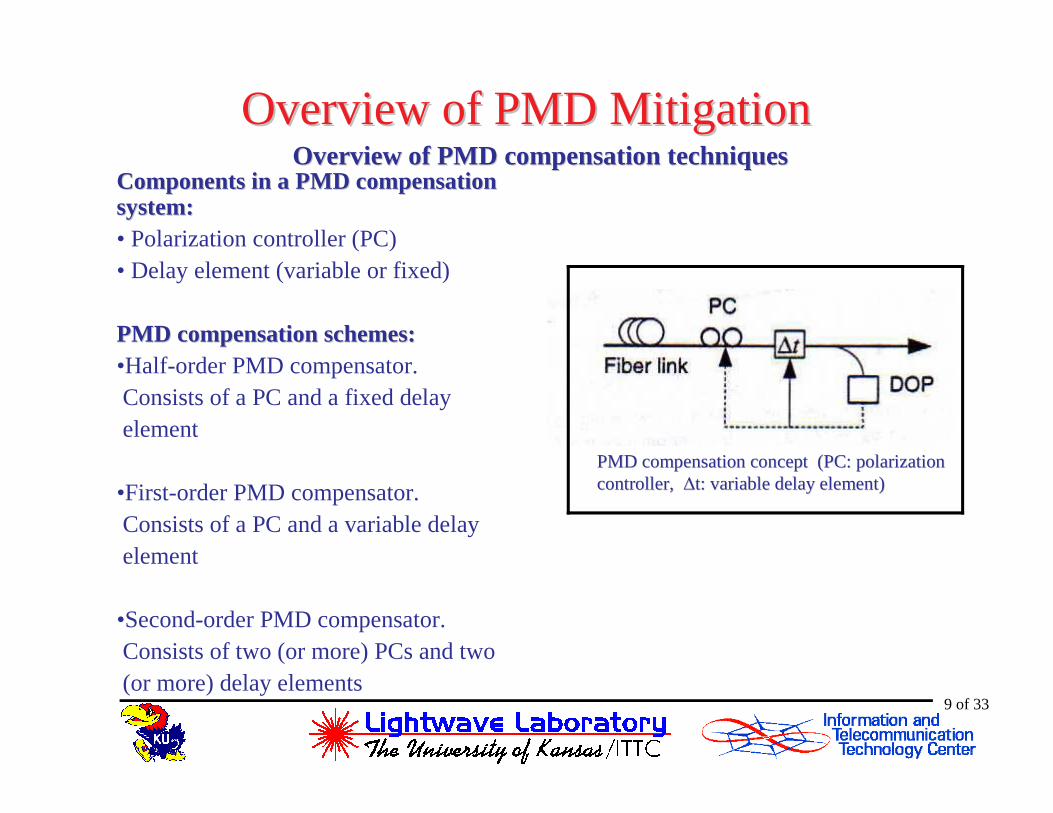
Experiments, Inferences and Field TrialExperiments, Inferences and Field TrialField tr ial of the PMD compensation systemField tr ial of the PMD compensation system• To test the PMD compensation system on an underground fiber-optic link
• Link length ~ 95 km
• Chromatic dispersion measured to be ~ 1550 ps/nm at 1534 nm. Necessitated chromatic dispersion compensation.
• Power budgeting performed to minimize impact of optical amplifier noise
System parameters:System parameters:
• Operating wavelength: 1534 nm
• Data rate: 10 Gb/s
• Waveform: NRZ (non return to zero)
• Bit sequence: PRBS (pseudo-random bit sequence), 223-1
21 of 33

Experiments, Inferences and Field TrialExperiments, Inferences and Field Trial
AgilentTransmission
Test Set(J2127A)
General PhotonicsPolarite-II
PolarizationController
Oprel EDFA
JDS Fitel PMDEmulator
KeopsysEDFA-1
KeopsysEDFA-2
PMDCompensation
System
EDFA (Noisesource)
Underground SMF link(95 km)
BPF-1
Underground SMF link(18 km)
DCF 80 DCF 20 DCF 10BPF-2
Field trial setField trial set--up (DCF: dispersionup (DCF: dispersion--compensating compensating fiber; BPF: bandfiber; BPF: band--pass filter)pass filter)
22 of 33

Experiments, Inferences and Field TrialExperiments, Inferences and Field TrialNumber of scrambling axes versus PMD compensation per formance:Number of scrambling axes versus PMD compensation per formance:• Number of polarization scrambling axes can be one or more• One-axis scrambling changes the state of polarization (SOP) over one great
circle on Poincare sphere• Two or more axes provide more complete coverage on the Poincare sphere• Test to find if the number of scrambling axes affected PMD compensation
performance
Procedure:Procedure:• Emulate a finite value of DGD using emulator• Perform PMD compensation with one-axis scrambling• Measure post-compensation BER • Perform PMD compensation with four-axis scrambling• Measure post-compensation BER• Compare BER values• Repeat as necessary
Poincare Poincare spheresphere
23 of 33
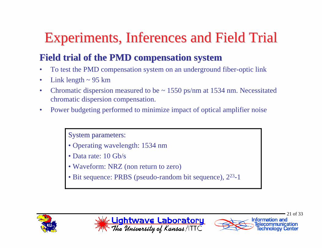
Experiments, Inferences and Field TrialExperiments, Inferences and Field TrialMeasured BER for emulated DGD of 0Measured BER for emulated DGD of 0 psps and 30and 30 psps
Emulated DGD (ps) Measured BER
0 6.26e-12
30 3.085e-11
Compensation performance with 4Compensation performance with 4--axis scrambling axis scrambling (emulated DGD=30(emulated DGD=30 psps))
Tr ial Compensated DGD (ps)
Measured BER
1 26 3.826e-12
2 24 2.426e-12
Compensation performance with 1Compensation performance with 1--axis scrambling axis scrambling (emulated DGD=30(emulated DGD=30 psps))
Tr ial Compensated DGD (ps)
Measured BER*
1 37 2.773e-12
2 24 4.159e-12
∗ SOP before the PMD emulator adjusted during BER measurement
Conclusion: Conclusion: PMD compensation performance is independent of number of axes ofPMD compensation performance is independent of number of axes of scramblingscrambling
24 of 33

Experiments, Inferences and Field TrialExperiments, Inferences and Field TrialMaximum DGD the PMD compensation system can compensate forMaximum DGD the PMD compensation system can compensate for
• Emulated DGD increased from 30 ps upward. DGD at which PMD compensation performance degraded was determined.
Conclusion:Conclusion:PMD compensation system can compensate for up to a maximum DGD oPMD compensation system can compensate for up to a maximum DGD of 40 f 40 psps
Comparison of BER measured after PMD compensation for different Comparison of BER measured after PMD compensation for different emulated DGD valuesemulated DGD values
25 of 33

Experiments, Inferences and Field TrialExperiments, Inferences and Field Trial
Scrambling frequency versus PMD compensation per formanceScrambling frequency versus PMD compensation per formance
• To demonstrate the importance of scrambling frequency
• Single-axis scrambling performed. Scrambling frequency varied from 5 Hz through1300 Hz
• 30 ps of DGD emulated for all trials
• At each scrambling frequency setting, PMD compensation performance was determined
• Degree of polarization (DOP) measurement sampling rate ~ 2500 Hz
• Measured BER with 0 ps emulated DGD was 6.26*10-12 (reference BER)
26 of 33
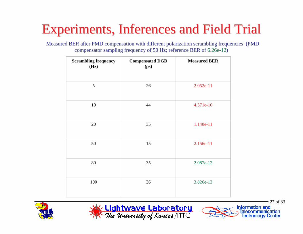
Experiments, Inferences and Field TrialExperiments, Inferences and Field Trial
Scrambling frequency (Hz)
Compensated DGD (ps)
Measured BER
5 26 2.052e-11
10 44 4.571e-10
20 35 1.148e-11
50 15 2.156e-11
80 35 2.087e-12
100 36 3.826e-12
Measured BER after PMD compensation with different polarizatioMeasured BER after PMD compensation with different polarization scrambling frequencies (PMD n scrambling frequencies (PMD compensator sampling frequency of 50 Hz; reference BER of compensator sampling frequency of 50 Hz; reference BER of 6.26e6.26e--1212))
27 of 33

Experiments, Inferences and Field TrialExperiments, Inferences and Field TrialMeasured BER after PMD compensation with different polarization Measured BER after PMD compensation with different polarization scrambling frequencies scrambling frequencies
(PMD compensator sampling frequency of 100 Hz; reference BER of(PMD compensator sampling frequency of 100 Hz; reference BER of ≈≈ 1010--1313))
28 of 33
Scrambling frequency (Hz)
Compensated DGD (ps)
Measured BER Comments
200 26 6.608e-12 Lengthy tracking
400 36 3.3e-13 Lengthy tracking
700 36 1.009e-11 -
1200 19 2.504e-11 Lengthy tracking
1300 25 1.461e-11 Lengthy tracking

Experiments, Inferences and Field TrialExperiments, Inferences and Field TrialConclusion:Conclusion:
• PMD compensation performance degrades when polarization scrambling frequencyis less than the sampling rate of PMD compensation system
• Also, performance degrades when scrambling frequency approaches the DOPmeasurement sampling rate. In addition, tracking cycles are initiated too often(lengthy tracking).
• Optimum scrambling frequency range: 80 Hz – 100 Hz
29 of 33

Summary and ConclusionsSummary and Conclusions• An adaptive PMD compensation system was modified into a robust and bit-rate-
independent one.
- DOP-based PMD monitoring incorporated.
• Time taken for one complete compensation cycle was determined to be 100 s
• OSNR tests conducted on PMD compensation system. Satisfactory compensationperformance at received OSNR values of 10 dB and higher.
• Field trial of the PMD compensation system successfully performed on anunderground fiber-optic link
• PMD compensation performance determined to be independent of the number ofaxes of polarization scrambling
• Limit of PMD compensation system identified to be about 40 ps of DGD.
• Importance of polarization scrambling frequency experimentally verified30 of 33

Scope for Future WorkScope for Future Work
• Replacement of the HP-8509B Polarization Analyzer with a compact, high-speedDOP measurement device
• Testing PMD compensation system at 40 Gb/s data rate
• Evaluation of PMD compensation performance in mitigating second-order PMDeffects
• Testing PMD compensation system performance for RZ (return-to-zero) format
31 of 33

AcknowledgementsAcknowledgements• Spr int CorporationSpr int Corporation (transmission test set)
KUKU--L ightwave Lab:L ightwave Lab:
• Juan M. Madrid (development of PMD compensation program, design andfabrication of interface board)
• Ashvini Ganesh (chromatic dispersion measurement and compensation)
• Renxiang Huang (design of voltage inversion and scaling circuit)
32 of 33

THANK YOUTHANK YOU
33 of 33