
Development of Advanced Diesel Particulate Filtration (DPF ... · PM filtration mechanisms have not...
19
Development of Advanced Diesel Particulate Filtration (DPF) Systems Particulate Filtration (DPF) Systems (ANL/Corning/Caterpillar CRADA) February 26, 2008 DOE Merit Review PI: Kyeong Lee (Postdoc: Joe Song) Transportation Technology R&D Center Transportation Technology R&D Center Argonne National Laboratory DOE Project Managers: Kenneth Howden & Gurpreet Singh Office of Vehicle Technologies Office of Vehicle Technologies This presentation does not contain any proprietary or confidential information
Transcript of Development of Advanced Diesel Particulate Filtration (DPF ... · PM filtration mechanisms have not...

Development of Advanced Diesel Particulate Filtration (DPF) SystemsParticulate Filtration (DPF) Systems
(ANL/Corning/Caterpillar CRADA)
February 26, 2008 DOE Merit Review
PI: Kyeong Lee (Postdoc: Joe Song)
Transportation Technology R&D CenterTransportation Technology R&D Center
Argonne National Laboratory
DOE Project Managers:
Kenneth Howden & Gurpreet Singh
Office of Vehicle TechnologiesOffice of Vehicle Technologies
This presentation does not contain any proprietary or confidential information

Motivation of Current DPF CRADA Project
� PM Emission Standards (2007 - 2010): U.S. Federal – Heavy-duty: 0.01 g/bhp-hr (90% reduction) – DPFs are known to be most promising for the efficient control of
PM emissions. � “Corning wants to further improve material properties, related to the
d bili fil i / i ffi i i dpore structures, durability, filtration/regeneration efficiencies, and back pressure.”
�� CaterpillarCaterpillar • Technical and intellectual capabilities of Argonne will provide the
fundamental understanding necessary to derive efficiency of aftertreatment systemsaftertreatment systems.
• Working closely with the industry leader in PM filtration will accelerate the learning process and eventually a choice of diesel aftertreatment technologygy.
2

�
t t t t t
Purpose of Work � Characterize filtration and regeneration processes in the course ofCharacterize filtration and regeneration processes in the course of
visualization (both still and video images) by micro-imaging system. – Establish a bench-scaled flow reactor (which simulates filtration and regeneration
processes of DPFs)), and a µ-imagg ging syystem ((which consists of a stereo-microscoppe,p µCCD camera, and image acquisition software).
�Provide efficient filtration/regeneration strategies for industry sponsors. – Reduce the DPF pressure dropReduce the DPF pressure drop – Evaluate material durability caused by regenerations and ash build-up – Reliable start of regeneration at low exhaust temperatures (elec. heater, fuel injection) – Thermal run-away control – Characterize properties of deposits (soot cake & ashes) in terms of morphology,
nano-structures, and chemistry – Characterize properties of nano-particles (< 100 nm) and find control technologies
�Parametric studies – Engine operating conditions Æ Effects of particle size, fractal geometry, chemistry – Exhaust gas compositions (NOx, O2)
FiltFilter materiiall an dd geometry (Cordi dierite vs. SiC SiC, catallyst, pore siize, porositity))– (C i
3

�
Previous Review Comments Other institutes such as Univ of Minnesota Michigan Tech and� Other institutes, such as Univ. of Minnesota, Michigan Tech., and PNNL, have done similar work. ¾ Detailed microscopic analysis on DPF filtration and regeneration processes have
not been done yyet. Instead, theyy mostlyy conducted DPF syystem pperformance tests on engines or vehicles.
¾ Detailed morphological characteristics of PM emissions have not been considered in their research. For examples,
Single nucleus
CeO2 nano-particles
10 nm
Multiple nuclei
nebulous amorphous aromatic
10 nm
nuclei
graphiticdistinct iso-paraffin
Engine operatingEngine operating NanoNano-structuresstructures Fuel properties Fuel additives Fuel additives Fuel properties conditions effects effects effects effects
4

–
Barriers � PM filtration mechanisms have not been revealed to the same scale
as nano-sized diesel particulates. – Nano-particle control technologies.
� PM regeneration causes material failure during the period of high thermal-energy release, due to thermal run-away. – Optimal regeneration schemesOptimal regeneration schemes.
� Use of DPF systems may result in an excess energy consumption. – Operational schemes of DPF system with minimized energy input.
� A high-resolution µ-imaging system is required to provide images for diesel particulates and filter-membrane structures.
� Experimental equipments and conditions must be scaled down ffor bench-tests.
5

�
Approach � Schematic of Experimental SetupSchematic of Experimental Setup
Adjustable bypass valve
Exhaust pipe CAT-C7 Exhaust pipe CatalystEngine
2.51 Flow meter/controller
P-Transducers 2.51
Thermocouples Heating
Reactorsystem
FlFlue Gases
µ- Imaging System
Linear translation system
6

Accomplishments Contributions from industry sponsors have been significant Contributions from industry sponsors have been significant
� Corning
– Wall-flow type cordierite membranes (full/bench scales, various models) flow type cordierite membranes (full/bench scales, various models)Wallwith detailed material properties
– Accurate diamond-cutting, canning, and assembly-part supply
100/17
200/12
Φ2” X 6” bisected Φ2” X 6” Canned DPFCanned DPF
Φ5.66” X 6” bisected (bench scale) (bench scale) (F ll scale) (Full scale)
7

�
Contributions from Industry Sponsors (cont’d)� Caterpillar
– Catalytic coating of membranes – Development of a diesel-simulating combustor for PM generation. – A most advanced 2007 model C7 diesel engine has been delivered to
Argonne (07 EPA Certified).
� 7.2L Inline 6-cylinder, DI, T/C, EGR
� CAT Common-rail Injection 350 h @ 2400 � 350 hp max @ 2400 rpm; 860 lb-ft @ 1440 rpm
� The engine requires aftertreatment system toaftertreatment system to comply with 07 EPA emissions regulations.
8

A unique Flow/Thermal Reactor has beendesigned and fabricated successfullydesigned and fabricated successfully
(11 ½”)
(8 ½”)
� Module design � Durable design; a total
weight of 50 lb � Air-tight visualization
quartz window:Auto-CAD design completed with safety review 3-1/2” x 1-3/4
9

–
The State-of-the-art stereo-microscopic imaging syystem pprovides unpprecedented higgh-resolution
still and video images
Leica stereo microscope (x640)
� Q-Imaging Retiga-EXI digital color CCD camera:
�� Leica stereo
– Ultra-high sensitivity and speed
1920x1040 (1 5M pixels)1920x1040 (1.5M pixels) – Video image: 110 fps
max; 10 fps @ full resolution
� Two light sources
10

t
Microscopic Imaging System (cont’d)
� Pneumatic optical table – vibration free
� X-Y remote/motorized linear translation system
� 3 pressure transducers (abs. & differential)
� 2 fl 2 flow meters � 16 thermocouples
adaptable
11
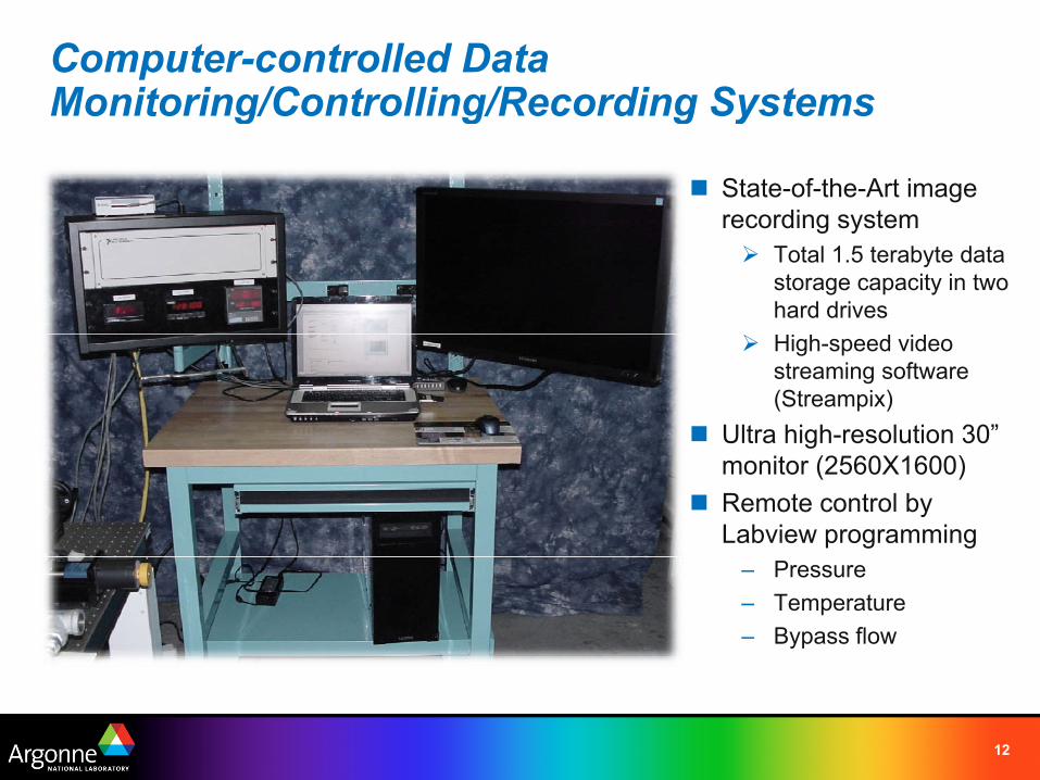
Computer-controlled DataMonitoring/Controlling/Recording SystemsMonitoring/Controlling/Recording Systems
� State-of-the-Art image recording systemrecording system ¾ Total 1.5 terabyte data
storage capacity in two hard drives
¾ High-speed video streaming software (Streampix)
� Ultra higgh-resolution 30” monitor (2560X1600)
� Remote control by Labview programming
– Pressure – Temperature – Bypass flow
12

t
�
p
A customized Labview program remote-controls bypassing emissions flows for the lab-scaled membranebypassing emissions flows for the lab scaled membrane
Speed Mtotal Texh Qexh Qbypass
(rpm) (g/min) (°C) (scfm) (scfm) 2400 20088 591 9.2
B C l S h
500
� Bypass Control Scheme
1440 12053 500 355 5.51440 12053 500 355 5.5 700 3054 100 90 1.4
� MMembbrane volume rati tio = 64:1l 64 1 (commercial : lab-scale)
Open bypass valve
Measure QbypassMeasure Qbypass
∆Q<0.001
Yes
No � 7.2L CAT C7 engine
Set Qinitinit
Start Filtration
13

The DPF testing system needs to be integrated with the CAT’s most advanced C7 diesel enggine installed
on a dynamometer.
14

Experimental Results � Microscopic observation of DPF membrane structures has been successful.
Plugged end
2 mm
Still image – low magnification (x51) Video image (10 Sec, 490 Mb)
• Mean pore size: 20 – 30 µm • Total volume of pores can be measured in collaboration with our Chemistry Div. .Total volume of pores can be measured in collaboration with our Chemistry Div
15

The µ-imaging system associated with automated translation syystem pprovides an extra cappabilityy for
material defect inspection
16

Technology Transfer
�Corning – Provide design criteria for developing advanced DPF membrane
materials which are durable for thermal reactions and highly efficient in materials, which are durable for thermal reactions and highly efficient in filtration and regeneration.
�Caterpillar
– Provide design criteria for developing a low-energy consumption, highefficiency DPF system, which is optimized for CAT’s C7 engine.
17

FY08 Research Plans and Collaborations
� FY08FY08 researchh pllan – µ-images of membrane pores during filtration and regeneration – Filtration/regeneration efficiencies; ignition energy consumption – Morphology of soot deposits – Parameters to be varied
• Engine speed and load • Gaseous emissions composition • Inlet gas temperature
– CAT’s C7 engine installation on a upgraded dynamometer
� Collaborating research partners – Univ. of Wisconsin – Madison (Prof. Foster) – Honda Motor in Japan
� Complimentary Part Supply – Iljin Electric Co. (DPF heating systems for regeneration)
18

– -
�
Summary
� Experimental setup for DPF filtration and regeneration tests has been completed. – Flow reactor with PM sampling system µ-imaging system dataFlow reactor with PM sampling system, µ imaging system, data
acquisition system with custom-made Labview programs, remote/auto control systems.
� Visualization of membrane substrates has successfully been achievedVisualization of membrane substrates has successfully been achieved at a high resolution. – Both still- and video-images.
� In addition, an automated material inspection system has been developed.
19


