DEVELOPMENT OF A WEB-BASED SOFTWARE …repository.um.edu.my/599/1/Software Project Management...
201
DEVELOPMENT OF A WEB-BASED SOFTWARE PROJECTS MANAGEMENT APPLICATION USING ORACLE APPLICATION EXPRESS IRSHAD UR REHMAN DAR DISSERTATION SUBMITTED IN FULFILMENT OF THE REQUIREMENTS FOR THE DEGREE OF MASTER OF COMPUTER SCIENCE FACULTY OF COMPUTER SCIENCE AND INFORMATION TECHNOLOGY UNIVERSITY OF MALAYA KUALA LUMPUR JANUARY 2011
Transcript of DEVELOPMENT OF A WEB-BASED SOFTWARE …repository.um.edu.my/599/1/Software Project Management...

DEVELOPMENT OF A WEB-BASED
SOFTWARE PROJECTS MANAGEMENT APPLICATION
USING ORACLE APPLICATION EXPRESS
IRSHAD UR REHMAN DAR
DISSERTATION SUBMITTED IN FULFILMENT OF THE
REQUIREMENTS FOR THE DEGREE OF MASTER OF COMPUTER
SCIENCE
FACULTY OF COMPUTER SCIENCE AND INFORMATION
TECHNOLOGY
UNIVERSITY OF MALAYA
KUALA LUMPUR
JANUARY 2011
ii
ABSTRACT
The current Software Project Management Application used by Longbridge Consulting
Sdn Bhd is based on the use of excel worksheets. As a Small Medium Enterprise
(SME), Longbridge Consulting Sdn Bhd is unable to utilize commercial project
management solutions to the simple fact that these software’s are costly, complicated
and cumbersome to implement for their software development projects. Common issues
faced by the project manager are difficulties in keeping track of project details such as
project status, tasks, milestones and also the important task of report generation. These
issues are in no way unique and limited to just Longbridge Consulting Sdn Bhd as there
are yet many organizations today that are also facing these exact same problems.
This research presents a prototype Web-based Software Project Management
Application (SPMA), which is developed on the Oracle Apex. Apex is a browser-based
web development tool that enables the rapid development of database-centric web
applications. The goal of creating the web-based Software Project Management
Application (SPMA) will be to provide an alternative solution that will be able to cater
to the above-mentioned problems while at the same time ensuring the project quality is
not sacrificed. Web-based Software Project Management Application (SPMA) caters to
several components of project management such as the managing of multiple projects
along with their associates, releases, tasks, milestones and features, tracking and the
overall monitoring of a project’s progress. Actions like generating reports can be done
on the fly whilst allowing real-time actions of creating, updating and viewing of project
details all of which can be done via online. The implementation of this application was
then measured by in terms of system data accuracy and system response time. During
evaluation the result showed that system data accuracy and system response of this tool
is almost 50% better and faster than excel based work sheets system.

iii
ACKNOWLEDGEMENTS
I would like to express my praise and gratitude to the Almighty ALLAH for HIS mercy
and countless blessings. I would like to Thank and express profound gratitude to my
supervisor, Mr. Mustaffa Kamal Nor and Mr. Mohd Harul Nizam, for their invaluable
support, encouragement, supervision and useful suggestions throughout this M.Sc.
Research work candidature. I would also like to express my gratitude to all my
University Lecturers for their guidance and support.
I am grateful for the cooperation of “Longbridge Consulting Sdn.Bhd” company by
allowing me to interview their CEO and Staff. First, I really appreciate the kindness of
Mr. Bob Gill CEO of Longbridge Consulting Sdn.Bhd, who gave me so much important
data for analysis. Additionally I would also like to thank Mr. Leung (DBA) and Mr.
Jasraj (System Analyst) of “Longbridge Consulting Sdn.Bhd” for their support and help.
They were willing to help me answer all my questions without hesitation. Moreover, I
would like to acknowledge all of my respondents who answered the survey.
I am thankful to my parents, for their moral and financial support and my brothers for
being in touch with me. I sincerely thank my friends who have supported me through
these years.

iv
Table of Contents
ABSTRACT................................................................................................................ II
ACKNOWLEDGEMENTS...................................................................................... III
TABLE OF CONTENTS ................................................................................................. IV
LIST OF FIGURES ........................................................................................................ IX
LIST OF TABLES......................................................................................................... XII
LIST OF ABBREVIATIONS........................................................................................... XII
1.0 CHAPTER 1 – INTRODUCTION ................................................................1
1.1 Background .......................................................................................................1
1.2 Problem Statement ............................................................................................3
1.3 Motivation .........................................................................................................4
1.4 Objectives..........................................................................................................4
1.5 Expected Outcomes...........................................................................................5
1.6 Research Significance .......................................................................................6
1.7 Organization of thesis .......................................................................................7
1.8 Conclusion ........................................................................................................8
2.0 CHAPTER 2 - LITERATURE REVIEW.....................................................9
2.1 Introduction .......................................................................................................9
2.2 Purpose of Software Project Management......................................................11
2.3 Software Project Management Activity Processed .........................................13
2.3.1 Project Planning ......................................................................................14
2.3.2 Monitoring the Project (Tracking) ..........................................................14
2.4 Advantages of Software Project Management Application ............................15
2.4.1 Software Project Management Application Capabilities ........................15
2.5 Existing Systems .............................................................................................17
2.6 Web-based Software Project Management Application (SPMA) vs. Other
Project Management Applications. .........................................................................21
2.7 Longbridge Consulting Sdn. Bhd....................................................................22
2.7.1 Their Services .........................................................................................23
2.8 Oracle Apex ....................................................................................................26
2.9 Conclusion ......................................................................................................27
3.0 CHAPTER 3 – METHODOLOGY .............................................................29
3.1 Introduction .....................................................................................................29

v
3.2 Research Methodology ...................................................................................29
3.2.1 Data Gathering ........................................................................................30
3.2.1.1 Unstrucured Interview .……………………………………….31
3.2.2 Design and Coding..................................................................................31
3.2.2.1 Capturing System Requirements………………………………33
3.2.2.2 Coding………………………………………………………....33
3.2.3 Testing and Evaluation............................................................................34
3.2.4 Implementation .......................................................................................35
3.2.4.1 Parallel Approach...……………………………………………35
3.2.5 Analysis and Result.................................................................................36
3.2.6 General Discussion .................................................................................37
3.3 Conclusion ......................................................................................................37
4.0 CHAPTER 4 - ANALYSIS AND DESIGN.................................................39
4.1 Introduction .....................................................................................................39
4.2 System Analysis ..............................................................................................39
4.2.1 Requirements Structure...........................................................................40
4.2.1.1 Process Modeling.…………………………………………….40
4.2.1.2 Conceptual Data Modeling……………………………………42
4.2.2 Requirements Specification ....................................................................43
4.2.2.1 User Requirements..……..……………………………………45
4.2.2.2 Functional Requirements……………………………………...46
4.2.2.3 Non-functional Requirements ….…………………………….46
4.2.2.4 Data Flow Diagrams…...……………………………………...47
4.2.2.5 Hardware Requirements..….………………………………….47
4.2.2.6 Software Requirements.....…………………………………….48
4.3 System Design.................................................................................................48
4.3.1 Logical Design ........................................................................................50
4.3.1.1 System Interface Design...…….………………………………50
4.3.1.2 Database Design...….…………………………………………52
4.3.2 Physical Design.......................................................................................56
4.4 Conclusion ......................................................................................................56
5.0 CHAPTER 5 – SYSTEM PROTOTYPE AND TESTING .......................57
5.1 Introduction .....................................................................................................57
5.2 System Prototype ............................................................................................57
5.3 Software Projects Management Application (SPMA) System Architecture ..63

vi
5.4 Software Projects Management Application (SPMA) Modules .....................66
5.5 Product Perspective.........................................................................................70
5.6 Testing.............................................................................................................70
5.6.1 Test Cases ...............................................................................................71
5.7 Conclusion ......................................................................................................74
6.0 CHAPTER 6 - EVALUATION AND CONCLUSION..............................75
6.1 Introduction .....................................................................................................75
6.2 User Evaluation...............................................................................................75
6.2.1 System Functionalities ............................................................................75
6.3 Comparison with Existing System..................................................................83
6.4 System Strength ..............................................................................................84
6.5 Limitations ......................................................................................................86
6.6 Future Directions of Work ..............................................................................87
6.7 Contributions...................................................................................................87
6.8 Conclusion ......................................................................................................88
REFERENCES..........................................................................................................89
APPENDIX A – INTERVIEW QUESTIONNAIRE .............................................92
APPENDIX B – ERD DIAGRAMS.........................................................................95
APPENDIX C – DFD DIAGRAMS.........................................................................96
APPENDIX D – DETAILED DFD DIAGRAMS.................................................105
Create Project ....................................................................................................105
Update Project...................................................................................................106
Delete Project ....................................................................................................107
View project details ..........................................................................................108
Search Project....................................................................................................109
Create Tasks ..........................................................................................................110
Update Task ......................................................................................................111
Delete Task .......................................................................................................112
View Task details..............................................................................................113
Search Task .......................................................................................................114
Create Features......................................................................................................115
Update Feature ..................................................................................................116
Delete a Feature.................................................................................................117
View Features details ........................................................................................118
Search Features .................................................................................................119

vii
Create Milestone ...................................................................................................120
Update Milestone ..............................................................................................121
Delete Milestone ...............................................................................................122
View Milestone details......................................................................................123
Search Milestone...............................................................................................124
Create Releases .....................................................................................................125
Update Releases ................................................................................................126
Delete Releases .................................................................................................127
View Releases details........................................................................................128
Search Releases.................................................................................................129
Create Links ..........................................................................................................130
Update Links .....................................................................................................131
Delete Links ......................................................................................................132
View Links details ............................................................................................133
Search Links......................................................................................................134
Create Organization ..............................................................................................135
Update Organization .........................................................................................136
Delete Organization ..........................................................................................137
View Organization details.................................................................................138
Search Organization ..........................................................................................139
Create Contributor.................................................................................................140
Update Contributor............................................................................................141
Delete Contributor.............................................................................................142
View Contributor details ...................................................................................143
Search Contributor ............................................................................................144
Create Category.....................................................................................................145
Update Category ...............................................................................................146
Delete Category.................................................................................................147
View Category details .......................................................................................148
Search Category ................................................................................................149
APPENDIX E –APPLICATION TEST RESULT AND GUI.............................150
APPENDIX F – USER EVALUATION................................................................177
APPENDIX G –USER MANUAL .........................................................................179
Deploying Application ..........................................................................................179
Move the Application Definition ......................................................................179

viii
Import Application Definition to Production Instance......................................179
Load the Data ....................................................................................................184
Alternate Authentication Mechanisms to Consider ..........................................184
Create Users ......................................................................................................185
Publish the URL................................................................................................188

ix
List of Figures
Figure 3.1 Activities........................................................................................................30
Figure 4.1 Context Diagram............................................................................................41
Figure 4.2 Interface Login Screen...................................................................................51
Figure 4.3 Interface for Dashboard Screen .....................................................................52
Figure 4.4 Table structure ...............................................................................................54
Figure 4.5 Table Structure-cont ......................................................................................54
Figure 4.6 Table structure-cont .......................................................................................55
Figure 4.7 Table structure-cont .......................................................................................55
Figure 5.1 Software Project Management Dashboard ....................................................58
Figure 5.2 User Interface: Project ...................................................................................59
Figure 5.3 User Interface Tasks ......................................................................................60
Figure 5.4 User Interface Features ..................................................................................61
Figure 5.5 User Interface Milestones ..............................................................................62
Figure 5.6 User Interface Releases .................................................................................63
Figure 5.7 SPMA Application ........................................................................................64
Figure 5.8 Oracle HTTP server (Apache) with mod_plsql .............................................65
Figure 5.9 Embedded PL/SQL Gateway.........................................................................65
Figure 5.10 Software Project Management Modules.....................................................66
Figure 5.11 Invalid User .................................................................................................71
Figure 5.12 Valid User....................................................................................................72
Figure 6.1 Create delete and update Project....................................................................76
Figure 6.2 Create delete and update Task .......................................................................76
Figure 6.3 Create delete and update Features .................................................................77
Figure 6.4 Create delete and update Milestone...............................................................77
Figure 6.5 Create delete and update Releases.................................................................78
Figure 6.6 Single view of Project Status.........................................................................78
Figure 6.7 Login Control ................................................................................................79
Figure 6.8 Data Accuracy ...............................................................................................80
Figure 6.9 Data retrieval from the search Mechanism....................................................80
Figure 6.10 Effectiveness in achieving its Objectives ....................................................81
Figure 6.11 System response Time .................................................................................82
Figure 6.12 System reporting Generation .......................................................................82
Figure 8.1 ERD Diagram ...............................................................................................95

x
Figure 11.1 Login Screen..............................................................................................150
Figure 11.2 Invalid User ...............................................................................................151
Figure 11.3 Project Management Dashboard................................................................152
Figure 11.4 Create Project.............................................................................................153
Figure 11.5 Create Project cont.....................................................................................153
Figure 11.6 View Project ..............................................................................................154
Figure 11.7 Update Project ...........................................................................................155
Figure 11.8 Delete Project.............................................................................................156
Figure 11.9 View Task..................................................................................................157
Figure 11.10 Create Task ..............................................................................................158
Figure 11.11 Update Task.............................................................................................159
Figure 11.12 Delete Task ..............................................................................................160
Figure 11.13 Download Task Details............................................................................161
Figure 11.14 Task Detail CSV......................................................................................161
Figure 11.15 View Features ..........................................................................................162
Figure 11.16 Create Feature..........................................................................................163
Figure 11.17 Update Feature.........................................................................................164
Figure 11.18 Delete Feature..........................................................................................165
Figure 11.19 View Milestone........................................................................................166
Figure 11.20 Create Milestones ...................................................................................167
Figure 11.21 Update Milestone.....................................................................................168
Figure 11.22 Delete Milestone......................................................................................169
Figure 11.23 Download Milestone Details ...................................................................170
Figure 11.24 Milestone Details CSV ............................................................................170
Figure 11.25 View Releases..........................................................................................171
Figure 11.26 Update Releases.......................................................................................172
Figure 11.27 Delete Releases........................................................................................173
Figure 11.28 View Links ..............................................................................................174
Figure 11.29 Create Links.............................................................................................175
Figure 11.30 Single View Detail For Projects ..............................................................176
Figure 11.31 Graphical View For All Open Tasks .......................................................176
Figure 12.1 Apex Workspace Login Home page..........................................................180
Figure 12.2 Apex Application Import Homepage ........................................................180
Figure 12.3 Apex Application Import/Export Page ......................................................181
Figure 12.4 Import Apex Application...........................................................................182

xi
Figure 12.5 Application Successfully Imported............................................................182
Figure 12.6 Install Apex Application............................................................................183
Figure 12.7 Application Installed Successfully ............................................................183
Figure 12.8 Apex Workspace homepage for Creating Users........................................185
Figure 12.9 Manage Application Users ........................................................................186
Figure 12.10 Enter User Details....................................................................................187
Figure 12.11 Create Users............................................................................................187
Figure 12.12 Application User Dashboard....................................................................188

xii
List of Tables
Table 2.1 SPMA Vs. Other Project Management Applications......................................21
Table 3.1 Results.............................................................................................................37
Table 4.1 Database table Keys ........................................................................................53
Table 5.1 Test Case Scripts.............................................................................................73
Table 5.2 Test Case Scripts-Cont....................................................................................73
Table 6.1 Comparison between new and Existing System .............................................83
Table 6.2 How Problem solved…………………………………...…………………....84
List of Abbreviations
DFD: Data Flow Diagram.
ERD: Entity Relationships Diagram.
SPMA: Software Project Management Application.

1
1.0 CHAPTER 1 – INTRODUCTION
1.1 Background
In this journey of new era, software development plays an important role because
people use computers in their daily life to do their work with ease and to save time. To
use computers means to use different applications to perform different functions in the
aim of lessening our burden and therefore software development has major part to do.
As we enter the software development the first and foremost thing that plays an
important role for the success of the project or the software developed is project
management. According to Friedlein (2001), the two primary skills a project manager
should possess are “Communication” and “Knowledge”, (i.e. industry experience,
business disciplines and skills, and “all the connotations of experience and wisdom”).
Without the proper project management it is almost impossible to develop the software
within the budget and timeframe allocated. Project management carried out without
proper measurement cannot hope to complete the project within the confines of the time
and budget allocated. This is the case in both large-scale organizations and small-scale
organizations.
With the increasing size and complexity of software’s today, software development has
become a more complicated process and hence the requirement to take care of even the
simplest activity in the development process has become equally tedious. The problems
usually faced in the software developments are cost overrun, schedule overrun. At the
core of these problems lies the problem of poor estimation. Wrong estimation will
undoubtedly results in a disaster in the development process. Therefore effective
estimation is essential for proper project planning and control and is one of the most
critical and challenging tasks in the development process. Under-estimating a project
leads to quality degradation, employee over exploitation and setting short schedule and

2
hence results in missed deadlines. Over-estimating is equally if not even worse than the
previous condition i.e. allocating more resources to the project and thus increasing the
cost of the project outside of the predefined scope.
Proper planning of the project and tracking the project development is the second
essential task for assuring the success of the project. Once the estimates are available
the next task is to assign the tasks to individuals. Regular feedback from the
development process is helpful in determining the status of the task and the project.
Tracking allows the project manager to cater to any unexpected situation that might
arise while development is in process. As stated earlier, estimation plays the key role in
the management of the development process, it is essential that the model or the method
being used should be correct and stratified with the most recent data available and if
standard parameters are being used in the method then those parameters should be well
calibrated with the available data.
The Software Projects Management Application is a project management tool, which
will be able to manage multiple projects along with their associated phases, tasks,
features, milestones, and releases. This application will help project managers to avoid
unnecessary risks and issues, ensure project quality and improve productivity on the
whole. This application will utilize oracles latest development tool “Application
Express” (formerly known as HTMLDB) which will provide the application better
performance and results in order to meet organizational needs in terms of speed,
effectiveness and usability. Oracle application express is a rapid web application
development tool for the Oracle database which is 100% web based development and
PL/SQL driven.
Some of the futures available via application express are: fast development periods, a
100% web based development tool, ready to use components, professional look and
feel, easy to create prototypes, simple to deploy and straightforward to comprehend.

3
Application express is a fairly new application builder geared toward web development
and does not require the use of an application server.
1.2 Problem Statement
All projects managers may universally know the software development lifecycle, as it is
the founding block for any successful software project conception, initialization,
development and eventually deployment. However what is not well know is the various
stumbling blocks that may bring any software projects to a halt – resulting in missed
deadlines and overall failure in meeting the planned milestones.
Many organizations today, including software development houses, still face such
problem to a certain degree as every organization have their own different needs to
manage a particular software project, and some of the organization cannot afford to buy
a project management application as they are expensive and difficult to use. As most of
the organizations are still facing difficulties to manage their software projects resources
and their details are:
• Difficulty in achieving the required efficiency in their projects
• Difficulty in keeping track of their employee tasks in real time.
• Difficulty in keeping track of the overall project completion status.
• Unable to meet planned Milestone due to unplanned problems arising.
• Difficult to keep track of new features implemented.
• Difficult to keep track of new releases of the software product.
• Hassle for project managers to prepare reports on project tasks and
milestones.

4
1.3 Motivation
Today the use of software has become essential in our daily office lives. The
organizations which develop software must produce good quality product to satisfy the
customer and whilst ensuring to be within the budget, in order to be profitable. If there
is no profit it is mere waste to run an organization. Every person tries to be as
comprehensive as possible in his thinking and knowledge. As being in the software
industry for past 5 years in different companies where project details was not recorded
efficiently and new technology were being reviewed for best of the project estimation.
It is important to be aware about new technologies, which are being created every day to
which will enable businesses to be more agile and reliable. Willingness to develop this
application was a new enhanced development tool released by oracle i.e. “ORACLE
APEX”. As a rapid web application development tool for the oracle database, it can be
utilized as a productive tool to build applications that report on database data. The
success of project is directly proportional to the project management and the measures
taken by it.
1.4 Objectives
Software project management tools for developing software projects will enormously
help to reduce a lot of problems and will support the management to ensure the quality
of the product. This research is an attempt to highlight the reasons for delays and
incompleteness in software projects and to minimize them, reduce complexity and
ensure project quality by developing a prototype tool named Software Project
Management Application (SPMA). This tool will help and support the managers in
performing their responsibilities. Thus, what the tool can do is to provide sufficient
information in order to reach the right decision.

5
The following are the SPMA objectives:
♦ To identify the issues related with software project management in a software
industry.
♦ To design and develop a software project management application that helps
project managers in managing projects.
♦ To provide information for assigning personnel on the basis of their work
experience, qualification, and knowledge in specific area.
♦ To keep track of changes in project requirements.
♦ To produce valuable reports on each project, maintained by SPMA.
The research was carried out by analyzing, comparing and evaluating problems in past
researches from literature review and comparison of some software project management
techniques and tools. Survey on software project management was conducted and
analyzed to develop the prototype tool. It is hoped that SPMA will pave the way for
developing useful project management tools, which can reduce problems, attempt to
ensure quality and to allow for better software project management.
1.5 Expected Outcomes
The potential goal of this project will be to produce a software projects management
application that can be applied to all software companies, in order to assist their project
managers in their planning, implementation and finally deployment. It is hoped that this
will eventually result in such organization as these software development consultancies
having the best (or most appropriate) application assisting them with their project
management.
The maximum potential that are predicted as an eventual outcome from the
development of this application are:

6
• Offer project managers a means for achieving higher efficiency in their
projects
• Enable project managers to track their employees’ tasks.
• Enable project managers to easily get updated project status.
• Enable project managers to efficiently schedule and achieve their project
milestone.
• Enable project managers to keep track of new features implemented
• Enable project managers to keep track of new releases.
• Enable project managers to prepare detailed and timely reports on project
tasks and milestones.
1.6 Research Significance
Global E-Commerce and E-Governance programs have brought into sharp focus for the
need of database systems to store and manipulate data efficiently (Sayed and Shamsul,
2009). It doesn't matter how big the company is, all it needs is a software project
management applications to stay on top of the game. Management software helps to
make sure that project details will be seen by everyone involved in the project whenever
they need to. Effective communication is one of the major challenges to a project’s
success (Thomas et al, 1999). This material can be shown in a number of ways using
charting or report applications whereby users are given the option to restrict or
otherwise control access depending on exactly what each person on the project is doing,
including everything from read-only access to full project editing rights. While user
may not see the need for it now, they will usually find it helpful at least once during the
project.
Users can handle or edit the schedule during each stage of their project. Most Software
project management applications will ease the communication process between user and

7
the client, as well as the others involved. This helps users to take away the pressure of
organization, as the management software is always there to refer to when needed. If
company is worried about giving information that isn't relevant or useful to the client,
software project management applications often help by restricting the client to certain
charts or reports, while others working on the project can have a wider range of access.
The management software might be digital (coming from an online source), which
offers a better form of project security.
Once a project is to reaching its completion, the pressure rises dramatically, making it
far more difficult than usual to delegate last-minute tasks, something that is almost a
certainty even where the best organized project are concerned. By training the team to
understands and utilizes the basic functions of software project management
applications, the project manager will save everyone a considerable amount of time and
frustration. This not only makes the project manager's job easier, it also makes everyone
else's job easier whilst allowing for a more cost-effective use of company's time.
Finally, when the project is finished, the management software will track and showcase
each team member’s efficiency at handling the tasks given him or her. Users are given a
clearer picture of their abilities, how they manage their time, and how they work in a
team. At the end of the day, web-based software project management applications can
greatly contribute to the success of project managers worldwide.
1.7 Organization of thesis
This project is organized into six chapters. Chapter 1 provides a short background,
identifies software project management related areas. Furthermore objectives, expected
outcomes and the problem statement are part of the chapter 1.
Chapter 2 will cover the literature review of software project management. This chapter
discusses about the purpose and activities in software project management. This chapter
8
also highlight on different types of web based software project management. The
advantages and what a software project management can do will be discussed. Existing
practice in Longbridge Consulting Sdn.Bhd will be reviewed.
Chapter 3 will discuss about the methodology applied in this research. Data gathering,
design and capturing system requirement will be also discussed in this chapter.
Chapter 4 will concentrate on the findings and analysis for the new proposed system.
Requirement structure, specification, system design and system architecture will be
discussed here.
Chapter 5 will focus on the system prototype. Deploying application, testing, test scripts
and system prototype will be shown and discussed.
Chapter 6 will conclude the evaluation and conclusion. User evaluation, system
functionalities, comparison with existing system, system strength and limitations will be
discussed. Recommendations for the future will be reviewed in this chapter.
1.8 Conclusion
Software project management issues described in this chapter represent the core of
project manager's toolbox for leading the project to successful completion. However, it
is important to stress that even if all of the important practices and issues could be
briefly covered here, software project management in reality requires a more detailed
insight into the practices themselves, as well as a lot of experience, judgment, and
intuition. Best practices of software project management are always those that can be
applied to the system being built, the technology the developers use, and the
organization that develops the system. In this way software project management
manages software projects and other aspects well.

9
2.0 CHAPTER 2 - LITERATURE REVIEW
2.1 Introduction
Decades ago, computers were used to serve specific functions. These standalone units
began to accumulate data to serve the individual departments. Little information passed
beyond the organizational boundary. As move towards the information age, cross-
boundary information needs become more important to provide organizations with the
leading edge (Zaitun et al., 2001).
The word project management is a combination of following activities (Kathleen et al,
2005):
• Organizing the work
• Estimating resources
• Allocation of resources
• Assigning tasks
• Controlling project execution
• Tracking and reporting progress
• Defining the products of the project
• Project Closure meets
In order to build a software project management one should able to understand the
project management and its activities, as project management is an immense area, which
includes all the activities in the above list. Quality, effort and time are inter-related. If
the project demands a higher quality then it is going to use more resources and the effort
required will be high and the effect will infiltrate to time. The first challenge that project
management faces is to ensure that the project is delivered within time and budget and
with the desired quality. The second challenge is more crucial and grueling one for
optimizing the resource requirements.

10
According to Fuller (1997), “Software project management is a set of principles,
methods, tools, and techniques for the effective management of achieving objective
oriented work.” Software project management allows the user to track the activities that
go into completing a project. Software project management helps the user track all of
the tasks as well as the resources required to complete them.
Software project management is the organization and management of resources in such
a way that all the work required to complete a project can be done within defined scope,
quality, and time (Kathleen et al, 2005). Increased pressure to reduce cost and delivery
time in a highly global and competitive environment has given due credit to project
management principles, techniques and tools. Software project management, in
particular, is an area of research with a view to achieve higher levels of quality and to
improve both cost and schedule estimates (Aneerav et al, 2007). Identifying tasks,
assigning people to interrelated tasks, obtaining and parceling out necessary materials,
meeting deadlines (or having fall-back plans when deadlines are not met), its mission is
to outcome as a constructive product or service. Software project management is the
organization and management of resources in such a way that all the work required to
complete a project can be done within defined scope, quality, and time and cost
constraints. Software project management differs from general project management, as
certain inherent characteristics are unique to software development (Hughes and
cotterell, 2006). These characteristics are invisibility, complexity, conformity and
flexibility.
• Invisibility implies that the process of developing the software cannot be seen (Is
not visual); thus it is difficult to control, monitor, measure and estimate project
progress.

11
• Complexity of software project is increased in that software projects include not
only the development, but also the implementation and maintenance of the
system that may be distributed and that interface with many existing systems.
• Conformity of software is essential. Traditional disciplines involve physical non-
changing resources, whereas software projects involve a variety of resources
where the software is expected to conform to the requirements of humans and
organizations.
• Flexibility is needed, as software systems are required to conform to the
standards of the organization. Thus it is subjected to a high degree of change.
Software that supports crucial business activities may be utilized to gain a competitive
advantage for its organization. In other words, the quality of the software development
process, as well as improvements in the development of the project management
software can significantly enhance the quality of the software (Schwalbe, 2006).
Since the operational environment of the software project management has changed,
new methods are needed to enhance and support standard software project management
practices. Different paradigms are evolving and several may hold promises to address
both this changing environment and the unique nature of software project management.
2.2 Purpose of Software Project Management
Resources and activities are the key players in any organization for completion of any
project. The purpose of Software project management is to first find out the activities
needed to take the project to its end and secondly to allocate resources to these activities
in a planned way.
Web-based software project management makes it easier to manage schedules and
resources, communicate project status, and report project information. A good

12
computer-based software project management package helps quickly determine whether
plans are feasible, spot potential pitfalls, and track the project to completion. Project
management methodology existed long before personal computers, but modern
computers make it easier to cover some of the more complex concepts. One of the most
challenging aspects of executing a complex project is the planning and tracking of all its
different stages. All the elements of the project need to broken down into sub-projects
that run in parallel but are ready to rejoin the main project at a certain time. These types
of challenges are just the type of problem project management software was designed to
tackle. The commercial software industry is about half a century old. In 1975, Fred
Brooks, in his classic text “The Mythical Man Month”, compared large software
systems development to the dinosaurs. As described an industry with excessive schedule
pressure, long overtime, and constant change and frequent overruns (McConnell, 2003).
In the intervening quarter-century, as software is integrated into more and more
products and process, little has changed from the negative picture painted by Brooks.
The often-quoted Standish (2009) “Chaos Report”, summarizing a survey of software
projects, reports that:
• Only 32% of software projects were completed on time and on budget.
• 24% of projects were cancelled before they ever get completed.
• 44% of projects were challenged (late, over budget and/or with less than the
required features and functions).
Problem solving is essential to software development. Indeed many of the basic
processes that are the backbone of software development can be viewed as standard
problem solving processes, ranging from requirements analysis, specification, and
design to testing or verification (Deek, 1999). As software development has increased
in complexity, an additional factor has grown in importance: collaboration. In fact, the
increasing complexity of applications has necessitated the use of teams or groups to

13
develop software because it is infeasible for individuals to develop large software
systems with appropriate expediency or levels of quality.
According to Prey (1996) computer scientists are not well prepared for this
contemporary environment because their preparatory training usually focuses on the
construction of small programs (programming-in-the-small) and provides little
experience in complex software development. In contrast, the development of large
systems in an efficient and timely manner requires a team effort, and the more
complicated the problem, the larger the team needed to solve it. Another contributing
factor to the need for team development is that domain-specific expertise tends to be
localized and geographically distributed. Studies have shown that, particularly when
such developers are dispersed, their success depends critically on their ability to use
effective software project management (Nunamaker, 1999). Such factors have made
teamwork in systems development a necessity, not merely a technically feasible option.
One of the local companies operating in Kuala Lumpur was chosen in this study. The
reason this local company was chosen was due to initial research on software companies
to understand why software projects get delayed. Though they did have Excel based
application and manpower but still they cannot meet deadlines and still can’t keep track
their software projects status. The following sections explain in detail about the findings
on the company and some brief explanations on their issues, which is feasible and
adequate to be implemented.
2.3 Software Project Management Activity Processed
Software project management has large number of activity processes but there are two
important activities for a project manager, as most critical activity that distinguishes
from others is “Project planning”. This is justified because the project plan is the

14
foundation of the whole project. The two important activities that lead the project to a
success are:
- Project planning
- Monitoring/Tracking
2.3.1 Project Planning
Projects are expensive in terms of both time and money. Ineffective planning may take
decades to complete a project with average complexity. Planning should be done
carefully before and during the development of the project as this helps in avoiding
serious mistakes. After the first phase, when requirements collection for the project is
over the next step is to identify the dependencies among the various modules and tasks,
and to pave a road map for the development process. Assigning right task to the right
person is a major challenge in this phase. Available estimates play a key role in whole
planning process by providing the information about the time and effort required for the
project and for various tasks in the project.
2.3.2 Monitoring the Project (Tracking)
When project is under development it is necessary to take feedback from the
development process and analyze the status of project. This helps in detecting any
problem occurred during development or any schedule or cost slippage and signals the
project management about the problem so that necessary actions could be taken to
rectify the problems. While tracking the status of the projects, the estimated values are
compared with the actual values collected during development.

15
2.4 Advantages of Software Project Management Application
For years, companies have struggled to deliver projects on time and within budget. But
with today's emphasis on getting more bangs for the buck, project management software
tools are more crucial than ever. This challenge has led many to turn to in-house project
management tools as a way to boost efficiency, cut costs, and improve on project
delivery in terms of time and budget. In spite of efforts made, these in-house solutions
often result in lengthy, costly and never-ending projects that force companies in areas
out of their field of expertise.
• Work more effectively as a team by sharing information
• Anticipate difficulties and conflicts, and easily modify plans as needed
• Identify and resolve resource allocation issues
• Make better decisions that affect the outcome of the project
• Determine the effects of making changes to the schedule, allowing us to be
proactive, and not just reactive
2.4.1 Software Project Management Application Capabilities
At the most basic level, Software project management will help organizations to
manage projects from start to finish, and allow employees at different levels to have an
input into the process.
Software Project management has been around for a number of years now and as a
result, it does far more than just manage the projects themselves. Project applications
can also carry out scheduling, cost control and budget management, resource allocation,
collaboration, communication, quality management and documentation or
administration. Projects can be complex and dependent on many different
factors, departments, and outcomes. As such, project software can help to determine
which events depend on one another, how exactly they depend on each other, and what

16
happens if things change or go wrong. In addition, they can schedule people to work on
various tasks.
People also use software project management to deal with uncertainties in the estimates
of the duration of each task; arrange tasks to meet various deadlines; and juggle multiple
projects simultaneously, following are some feature that help project managers to
manage projects.
i. Identify tasks
Task identity is an important component of the project, which needs to be identifying
for all the jobs that need to be done in a project and later on need to record in Web-
based software project management application for assigning to the appropriate team
members.
ii. Assign tasks
Once the tasks has been identified then each task need to be assigned to the appropriate
team members and record them in the Web-based software project management
application to achieve the goal of the project.
iii. Develop timelines for project milestones
Timelines are used to help team members to know what milestones need to be achieved
and under what time schedule. A project manager will be able to record the time line for
each task that has been created in the application for tracking of the project milestones.
iv. Enable Web-based Software Project Management
Web based applications are the ultimate way to take advantage of today's technology to
enhance organizations productivity and efficiency. Web based application gives an
opportunity to access business information from anywhere in the world at anytime. It
also facilitates to save time and money and improve the interactivity with customers and
partners.

17
Software project management application is to facilitate team access from anywhere, as
it is better for the team to track their project detail anywhere in the world. This feature
makes a project manager’s work easy to monitor the project status from any part of the
world.
2.5 Existing Systems
a. Trac Open Source Project
Trac is an enhanced wiki (wiki is a piece of server software that allows users to freely
create and edit web page content using any web browser) and issue tracking system for
software development projects. Trac uses a minimalistic approach to web-based
software project management. Their mission is to help developers write great software
while staying out of the way. Trac should impose as little as possible on a team's
established development process and policies.
Trac allows wiki markup (wiki markup is a lightweight markup language used to write
pages in wiki websites) in issue descriptions and commit messages, creating links and
seamless references between bugs, tasks, change-sets, files and wiki pages. A timeline
shows all current and past project events in order, making the acquisition of an
overview of the project and tracking progress very easy. The roadmap shows the road
ahead, listing the upcoming milestones.
Trac runs on any system supported by Python and the depending modules. Today we
are aware of people running Trac on various Linux distributions, Mac OS X, FreeBSD,
NetBSD and MS Windows. As trac software does not seem to be for all industries as of
its limited features there are many feature which Trac software is not capable to do, one
of them is data backup as this is one the important aspect of keeping data safe and for
future use if required.

18
Trac software is not capable of generating reports in .csv or excel format as it has own
report generator, which make users uncomfortable in today’s techno generation. It is
also difficult to install, as it has dependency that most people have problems with are
the Subversion Python bindings, which again require SWIG. There's not much can be
done about that though, seeing that Trac is a Python application integrated with
Subversion. Trac software is also difficult to install, as there are lot of thing that need to
be setup before installing.
b. Projectpier
ProjectPier is an open source community aimed at developing simple, powerful and
intuitive software for software project management and group collaboration. ProjectPier
gives a flexible system for managing projects involving multiple organizations by
providing a central place for all project activity and information while integrating with
users' existing tools and workflow. Thousands of people all over the world, from study
groups organizing a school project to large universities managing hundreds of
international research projects, are using this software to get a grip on their project's
tasks, communication, files and more. ProjectPier is a cross-platform application that is
written using PHP, JavaScript and a database backend like MySql. The system
requirements for this software are:
• Web server (Apache recommended) that can run PHP5 scripts (MySql, GD
and SimpleXML extensions are required),
• MySql database with InnoDB support (version 4.1 is recommended).
Being free software it still lack some of the requirements for the software project
management as reports has to be in a well formatted, easily accessed and downloaded
from the system, as this software does not generate reports in CSV or excel format. This
software also does not have the backup capabilities to maintain records for future use.

19
This software also does not keep trace of over all work done for the project, as project
managers need to review the overall project status to take the necessary action if there is
any delay or amendments for the project.
c. Microsoft Project
Microsoft project gives robust project management application with the right blend of
usability, power, and flexibility, so users can manage projects more efficiently and
effectively. Users can stay informed and control project work, schedules, and finances,
keep project teams aligned, and are more productive through integration with familiar
Microsoft Office system programs, powerful reporting, guided planning, and flexible
tools.
Microsoft Project has been extended with Microsoft office project server and Microsoft
project web access. Project server stores project data in a central database. Project web
access allows user to display and update this data over the Internet. Web access allows
authorized users to access a project server database across the Internet. Web access
includes timesheets, graphical analysis of resource workloads and administrative tools.
Being one of the commonly used project management software in today’s life as it has
some limitations and drawbacks which Microsoft need to overcome as they are:
• Only one user can view real time information and do updating. Other users
accessing the same project can only view-dated information.
• The organization will have to rely on one person to do updating on a
particular project.
• Microsoft project cannot view detailed, task-level information for resources
working on multiple projects from MS project professional. Detailed task
information is only available for one project at a time.

20
• Microsoft project requires MS project professional to control project and
resource data and then publish the information to the web. However, users of
MS Project web cannot edit the information but they can read, implying that
each project manager or resource manager requires a copy of MS Project
professional loaded on their terminal.
• Microsoft does not have a web-based tool for project managers and resource
managers to do updating. This will imply more costs and expenses.
• Team members do not have an opportunity to see the whole project work
and very often do not know what their colleagues are doing.
• It's hard to collect all the updates at one time.
• Top management does not have the full picture of the project and does not
know what each team member is busy with.
• Each user needs an updated version of Microsoft project to be installed on
his computer. It is very expensive and takes a lot of time to set up.
• Users always need to remember where the correct file is located.
• It’s impossible to control changes made to the file.
• The file does not provide the overall view for all the projects the
organization is involved in.
• Not every team member can update the file.
• Updates take time.
• Microsoft project server is a very expensive solution (up to $75 000, the set
up of which can take up to several weeks)
• Users need to also buy and install Microsoft Office Project Professional and
Microsoft Office Project Web Access.
• It's difficult to use and requires additional training of personnel.
• Only the project manager can update the whole schedule.

21
2.6 Web-based Software Project Management Application (SPMA) vs. Other
Project Management Applications.
Any project in business needs a proper project management. All the different elements:
personnel, components, paperwork have to come together at the right times to produce a
smooth flow and ensure deadlines are hit and money’s not lost.
There are many software project management tools designed for different complexities
of project, from small, two or three-person developments to massive company-wide
changes. Effective software project management helps us handle all the complex
projects of company’s business without interruptions from unclear roles,
miscommunication, convoluted tasks and lack of accountability.
Table 2.1 SPMA Vs. Other Project Management Applications
Software Application Trac Open Source Projectpier Microsoft Project SPMA
Language Phyton PHP Microsoft APEX
Database SqlLite MySql MS Sql 2000 ORACLE
Web based Yes Yes No Yes
Tracking Yes Yes Yes Yes
Multiple Project Yes Yes Yes Yes
Multiple User Yes Yes No Yes
User Admin Yes Yes No Yes
Backup No No Yes Yes
Privilages Yes No No Yes
User Access Control Yes Yes Yes Yes
Above table 2.1 shows the comparison between different project management software
with web-based software project management application (SPMA) and the comparison
shows that SPMA has more functionalities then the other three software stated in the
table 2.1. The comparison in the above table 2.1 is based on functionalities of the each
application stated on the left side of the table 2.1 as they are:
22
a) Language: Programming language that has been used to develop each
software stated in table 2.1 is Phyton, PHP, Microsoft and Apex.
b) Database: Database that has been used for storing data by each software
stated in table 2.1 is Sql Lite, MySql, Ms Sql 200 and Oracle.
c) Web based: This function represents which software stated in the table 2.1
has the web capability, were user can get the information of the
project in any where in the world.
d) Tracking: This function represents which software stated in the table 2.1
has the capability of tracking the project details.
e) Multiple Project: This function represents which software stated in the
table 2.1 has the capability of handling multiple projects.
f) Multiple User: This function represents which software stated in the table
2.1 has the capability of handling multiple users accessing at any point
of time.
g) User Admin: This function represents which software stated in the table
2.1 has the capability to have at least one user administrator.
h) Backup: This function represents which software stated in the table 2.1
has the capability of data backup.
i) Privileges: This function represents which software stated in the table 2.1
has the capability of granting privileges to a specific user.
j) User Access Control: This function represents which software stated in
the table 2.1 has the capability of controlling the user access, which
means limiting the access to a particular user.
2.7 Longbridge Consulting Sdn. Bhd
Longbridge Counsulting Sdn.Bhd is a private, Malaysian based organization, set up to
provide the required value-added, practical and skills-oriented services of the highest
quality. They are here to fulfill the needs of the customers that are in search of the
solutions to overcome the difficulties that are facing the Information and
communications (ICT) industry today.
Bob Gill spearheads Longbridge Consulting Sdn.Bhd. An early pioneer and veteran of
oracle, who was the fourth (4th) oracle Malaysia employee back in 1989. Bob has been
23
in the ICT industry for 27 years, with 22 years of oracle technical experience dating
back to 1985, when he first used oracle RDBMS V5, SQL*Forms V2 and the days of
RPT/RPF (Reports) on a WANG VS server. Bob, who brings both local and overseas
experience, expertise and ability that leads Longbridge Consulting Sdn.Bhd capabilities
and competencies in the area of oracle's core and java technologies.
Bob Gill has spent more than 13 years overseas providing his expert services in
Australia, England, Holland, Germany, Belgium, France and Taiwan. Since Longbridge
Consulting Sdn.Bhd inception, they have grown steadily and have a group of ICT
professionals who had worked and consulted for various local based organizations,
besides having gained international and overseas consultancy exposure in various
industries. Longbridge Consulting Sdn.Bhd has worked on several IT and
telecommunications projects, and are here to bridge the knowledge gap that is required
to help their customers to move forward into the future for mutual benefits.
2.7.1 Their Services
Longbridge Consulting Sdn.Bhd helps fit clients existing technology to their business
processes and problems, as well as identify their needs to successfully steer their
organization in the right direction towards business success through Longbridge
Consulting Sdn.Bhd services, solutions and innovations. From initial strategic planning
to rapid implementation of projects, consulting, outsourcing, support and training,
Longbridge Consulting Sdn.Bhd offers a one-stop service center for all ICT needs.
Besides being able to outsource the required technical expertise for company’s mission-
critical ICT projects, Longbridge Consulting Sdn.Bhd also offer a very cost-effective
model for application design and development though the procurement of their
application development framework, Longbridge Consulting Sdn.Bhd Secure
Framework. Longbridge Consulting Sdn.Bhd differentiate their services from others by

24
ensuring that these services are delivered to client to address the problem of skills
deficit and other critical issues that are being faced by the ICT industry today. The
services offered by Longbridge Consulting Sdn.Bhd are as follows:
a. Customized Application Development of client/server
Client-Server applications and n-tier architecture have always played a key role in
operation of businesses. Ability to input, process, store, and access data from anytime,
anywhere and any device is powering e-Businesses of today. Longbridge Consulting
Sdn.Bhd specializes in development of high-end client-server applications and robust
enterprise applications with user-friendly interfaces. Depending on business
requirements, their consultants and developers can also help in developing web-enabled
applications and systems.
b. Software Re-Engineering of Applications
Many companies today are thinking about how they can web enable their Oracle Forms-
based client server-based enterprise application suites, perhaps because of anticipated
competitive pressure, customer demands. The goal of conversion for web enablement
would be to maintain the business flow, business logic and functionalities while
achieving improvements in performance, scalability. As Longbridge Consulting
Sdn.Bhd offers Web-enablement of Oracle Developer client/server applications using
Developer 6i, 9i, 10g Developer Suite toolset and Conversion and Migration of
SQL*Forms 2.x, 3.x and Developer 2000 to Developer 6i, 9i, 10g Developer Suite
modules for their clients.
c. Application Architecture and Application performance Tuning
To survive at the architecture level, the IT specialists who do well are those who think
in terms of strategy, systems, policy, and procedures. Move beyond programming, and
25
learn new ways to approach security from a higher, application architecture level. Stay
ahead of security breaches and help ensure the enterprise is highly secure. Most
discussions of software security concentrate on the applications themselves or the data
they contain. As Longbridge Consulting Sdn.Bhd provides review of current application
architecture, database and application design, with special emphasis on performance and
also review of current security management of application, and providing consultancy
and services for improving this aspect of the application.
Longbridge Consulting Sdn.Bhd also has been performing application tuning analysis;
optimizing the 'expensive' SQL statements using new features and enhancements in
Oracle 9i/10g; and providing general guidelines for performance improvement, both for
client/server and web-based architectures for their client’s business improvement.
d. Systems Integration, Data Conversion and Migration
In today’s world, improving business efficiencies, driving up market share, and
achieving business results depend upon the intelligent application of technology. The
ability to organize and manipulate data from investments in hardware, software,
telecommunications and people is essential to the ability to solve business problems.
e. Database and Application Technical Training:
Longbridge Consulting Sdn.Bhd offers data base and application technical training
courses for their customers, which include generic and customized oracle 9i/10g
database and application-specific courses with advanced SQL, PL/SQL, optimization
and application performance tuning, and security management courses. As main aim is
to provide a better approach for project scheduling, it seems that it is difficult for
companies to keep track of their project schedule that is why most of their project’s gets
delayed.

26
2.8 Oracle Apex
Oracle has created software and services that enable organizations to get the most
accurate and up-to-date information from their business systems. Oracle remains in the
forefront in simplifying IT systems and provide complete solutions allowing customers
to get better information. Yet, like it or not, having the right IT system in place plays a
critical role in today’s business. A lesser known but powerful application development
tool that comes freely bundled with an oracle DBMS is oracle application express
(Oracle Apex). Over the past few years, the oracle application express has increased
twofold mainly because it is easy to use, saves money when consolidating spread sheets
and desktop databases, and comes with the bundled for free with oracle database
(Yuhanna and Megan, 2006). Oracle apex is a browser-based web development
environment that enables quickly develop database-centric web application. Apex was
launched, as an MS Access/Excel killer (Lorenzen, 2007). The focus has been on
consolidating fragmented information into the database in a user-friendly manner.
Oracle apex is a great tool, which keeps getting better with the each release.
Oracle apex and oracle database XE was chosen because of the fact that it is a freeware
software development environment based on the oracle database. Oracle database 10g
express edition (Oracle Database XE) is based on the oracle database 10g release 2,
code based that's free to develop, deploy, and distribute. As an on demand platform,
Apex provides a complete set of features for building business applications including
data models and objects to manage data, a workflow engine for managing collaboration
of that data between users, a user interface model to handle forms and other interactions,
and a Web services API for programmatic access and integration.

27
a) Apex and PHP
PHP is just scripting, like Perl, .Net, Ruby. It's a bunch of code. Apex uses declarative
objects like regions, reports, items, and validations. One has to hand code so much in
PHP where as it is already built into Apex like every aspect of interactive reports, or
validations. To build an application in Apex would take less time rather than to build in
PHP. PHP has almost always had a poor security record at best, with Oracle Apex it has
an excellent security out of the box and can add to that security base with minimal effort
(protection against cross site scripting, protection against SQL injection, session state
protection, custom authentication/authorization schemes, data encryption). Another
consideration to Apex is the maintainability of the site. PHP code grows to extreme
proportions quickly (again, because it is essentially a blank slate) and the only way to
manage that code is to do an extreme amount of documentation. Apex splits code up in
a nice visual format that separates validations, widgets, and regions on the page (which
also allows to leave a comment for each piece).
Regarding Apex and PHP, what's already been said: Apex is a framework with a lot of
pre-supported objects and a fully-supported environment, with PHP, it either have to
code everything by hand or surf the forums for code snippets to achieve the
functionality. PHP will allow you slightly more control at the cost of development time.
Apex gives a robust development environment and native database support out-of-the-
box. Setting things up from scratch using PHP, it is important to install the PHP add-ins
to whatever web server used and define database connections.
2.9 Conclusion
This chapter provides the background for both the exploratory and in-depth research of
the software project management. This chapter emphasized on the different project
management software and their functionality, which helps to understand the importance
28
of the software project management and its functionalities. The software products that
will be used for this research were defined. The service provide by the Longbridge
Consulting Sdn.Bhd were defined in order to understand the business point of view of
the company. The importance of this chapter is to understand and review the existing
software project management in order to fulfill the criteria of the software project
management.

29
3.0 CHAPTER 3 – METHODOLOGY
3.1 Introduction
This chapter describes the methodology chosen for this Project development.
Methodology is a collection of procedures, techniques, principles, and tools that help
developers build computer system.
Research methodology will be used during the application development phase. Research
methodology involves the use of qualitative data such as interviews, direct observations,
survey and analysis of documents and material. Questionnaire and documents review
are the research method used for developing this project prototype application.
3.2 Research Methodology
There are various methods in collecting information or more precisely data gathering. It
can be carried out by searching the related topic literatures, white papers, technical
papers, marketing reports, conferences proceedings, product data sheets, product
brochures, web pages, project focus groups, conducting interviews with experienced
personnel, distributing questionnaire, or even communicate to people. The research
methods used for this dissertation purpose are the review of literatures and books from
the Internet, unstructured interview and data gathering by distributing questionnaires. It
is important to know the consumers’ experiences and personal preferences and by doing
these will definitely contribute greatly to the development of this software prototype
application.
There several different types of activities that needs to perform in order to complete the
research as shown in figure 3.1 below:

30
Figure 3.1 Activities
3.2.1 Data Gathering
Gathering data is a frequent part of solving problems and satisfying curiosity. To look
up information to answer a question or to formulate new questions, to conduct surveys
and draw conclusions from them, in order to gather and analyzing data. Theoretically,
this research is based on the select perspective and other people’s previous research work
and studies, which covers and focuses on all the aspect of SPMA. The notion of SPMA and
its framework are studied and analyzed to suit the new development. Additionally, all the
ideas in SPMA related materials such as journals; Internet, newsletters, articles,
questionnaires, textbooks and Interviews have been extracted and analyzed to generate new
ideas and thoughts. The availability automated tools excel, spreadsheet and forms, which
have been gathered from the Longbridge Consulting Sdn Bhd are used as reference to
identify the weaknesses of the discipline, because the practical approach is the best way to
learn on how the system works. All the information gathered has been studied, and they
have been classified as the primary and secondary data. Formulas, standards and procedures
are specifically identified from the SPMA framework. Only relevant standards and
procedures are identified, gathered and interpreted to fit the new system.
31
3.2.1.1 Unstructured Interview
Unstructured interviews have been used in this research to gain a general understanding
of the requirements from the project manager’s point of view on the development of
project management software prototype application. An informal discussion with the
company employs has been done, by allowing the discussion to be open. The reason to
choose unstructured interviews for this research is because unstructured interview are
flexible, simple, informal and time saving when preparing for the interview. Interviewer
also has the freedom to change some questions or the sequence of the questions
according to the responses or reactions from the interviewees when having the face-to-
face discussions.
Face-to-face research method was chosen to use, such as interviews, as well as
opportunistic observation, to gather data. This approach was necessary because to gain a
broad understanding of the system, which necessitated open-ended, semi-structured
questioning techniques. Since the answers could be ambiguous face-to-face questioning
needed where feedback was immediate. Few staff members of Longbridge Consulting
Sdn Bhd were interviewed and each interview taking 10-15 minutes. Notes were taken
during and after each interview. Interviewed a cross section of staff – analysts,
managers, developers and testers, interview questions are stated in appendix a –
interview questionnaire.
3.2.2 Design and Coding
The design phase is concerned with describing how the system is to perform its task so
as to meet the new system requirement. In this research project, the design is divided
into two parts of an iterative process. Conceptual design enlightens the user on what the
system will perform whilst the technical design is a translation from the conceptual
design, but it provides a more detailed description in assisting a system developer to

32
understand the actual hardware and programming language needed to solve the
problem. In this research project, the conceptual design gives attention to the system
functions whereas the technical design expresses the form the system will take including
the hardware and software aspects.
The design phase is where the business requirements start to be translated into an IT
solution. Fundamental decisions are made in terms of the underlying technology. For
instance, will this be a web application or client/server, will the development require
visual basic or java, and will this system use SQL server, oracle, or DB2. The
technology utilized will be based on the needs of the project and the current technology
architecture used by the company. Online processes are translated into screens and
workflow definitions. Batch processes are defined. Online screen and report layouts are
built. Basically, the entire solution is built on paper (or using design tools) in a
deliverable such as a Technical System Design Report. When this phase is completed,
the solution can be turned over to the programmers to start implementing the solution in
code.
The other thing that happens at this point is that the high-level strategy documents
prepared earlier are fleshed out into more detailed planning documents. For instance, the
training strategy is used as input to create a training plan. The training plan describes in
detail what classes will be built, who will build them, who will teach them, who will be
taught, where the training will be held, what the outline of the classes is, and so forth. In
essence, just as the solution is designed, the training is also being designed in detail.
Likewise, a testing plan, data conversion plan, and implementation plan are created to
guide the detailed activities necessary for construction.

33
3.2.2.1 Capturing System Requirements
In software engineering, the first important thing is the need to understand what the
system is supposed to do. To determining the functional requirements for a system is to
identify its data flow. Data flow diagrams are used during the analysis phase of a project
to identify and partition a system’s functionality. Unneeded functionality should be
avoided, as they are the biggest waste in software development since it makes not just
the analysis phase but also every following phase longer (Poppendieck, 2003). This
model also serves as the foundation for all other development work. Data flow diagrams
partition the system into a set of logical, minimally related pieces, each of which
describes some ways in which the system will function.
3.2.2.2 Coding
The construction phase is the development process for many developers. (It is also the
start of the development process for many unsuccessful projects) Now the solution starts
to be implemented in code. The programming language that will be used in this
application is PLSQL and user interface will be in oracle’s newly enhanced tool known
as oracle APEX. Each developer will be unit testing as the application is being
developed. The primary goal of unit testing is to take the smallest piece of testable
software in the application, isolate it from the remainder of the code, and determine
whether it behaves exactly as expect. After unit testing, the testing plan, which describes
integration testing, system testing, and user acceptance testing guide the testing process.
Application developer will do integration test. The purpose of integration testing is to
verify functional, performance, and reliability, which also includes some kind of
behavioral as well as structural testing. System testing will be performed after the
system is implemented. Testers usually will try to break the system by entering data that
may cause the system to malfunction or return incorrect information. Once the system

34
testing will be over user acceptance testing will take place. User Acceptance Testing is
often the final step before rolling out the application. Usually the end users who will be
using the applications test the application before ‘accepting’ the application. This type
of testing gives the end users the confidence that the application being delivered to them
meets their requirements. This testing also helps nail bugs related to usability of the
application.
3.2.3 Testing and Evaluation
Testing is conducted by performing a validation of the implementation, to show if it
complies with the original requirements, specifications and design. Following are the
next steps to be performed in this research after system is ready.
• Unit testing
• Integration testing
• Systems testing
The developer will do unit testing and integration testing during the development phase,
as it is easier for them to rectify the error and fix them back at the same time. The end
users will do system testing based on the test scripts, which will be given to them once
the development phase is over. If any error occur during the system-testing phase it will
be recorded and send back to developer for a fix.
At this point, the fully tested solution is ready to be implemented. This could be as easy
as saying that system is now live or it could be as complicated as integrating a complex
series of related applications across multiple locations. Implementation could itself be
huge. However, if any one created an implementation strategy and implementation plan
up front, this now becomes a matter of execution. Implementation may still be complex,
but at least it doesn’t have to figure out everything from scratch. Depending on the

35
timing of the project, someone may also be training at this point, but again, it’s all in
line with the training plan.
3.2.4 Implementation
Implementation is the final step towards the newly developed system. This involves the
process of replacement of the existing system with the newly proposed and designed
system. The various methods available for the accomplishment of this purpose are:
• Direct approach
• Parallel Approach
• Pilot Approach
The system will be implemented using parallel approach. In this approach, the existing
system continues to function in parallel with the new system so that results generated by
it can verify. Once the organization become fully satisfied with the functionality and
output of the system, then old system will be discarded.
3.2.4.1 Parallel Approach
The parallel approach is the recommended approach for the new system
implementation. Parallel approach is the smart and safe implementing approach, which
would work in the light of the working environment. The current system, which is
running, would run as previously and the new system would enter the previous data of
the system. Both the existing and the new system will run side-by-side, for sometime.
Results of the two systems will be compared to provide both protection and control. The
length of parallel operation can vary. Usually the old system will retain through one or
two processing cycles with the new system. Parallel operations will provide users a
chance to become comfortable with changes before old methods disappear. This method
will also provide an opportunity to establish the improvement of the new system. Most

36
important of all, parallel approach, involves the least risk and the most protection of the
organization. The next step would be that the system would take the regular producing
data, although the data would be entered in manual system as well as the new system.
The old system report is the correct one and the new system report must be up to the
standard of the old report.
Now that application is complete, the next step is to deploy it. Typically, developers
create applications on one server and deploy it on another. Although this approach is not
required, it enables us to resolve bugs without impacting the production instance.
3.2.5 Analysis and Result
The purpose of the analysis is to define and communicate the goals and objectives that will steer
the project. The analysis allowed us to understand the project management process and issues
facing by project managers during the software development process. This analysis also helps
the researcher to use the appropriate methodology. Interview review and interaction with the
users gave broad rage of understanding of the system and how the process is processed during
development phase. As a result most of the candidates were desire to follow general capabilities
in project management tools.
• Multi-user capability.
• Multi-project capability and support.
• Easy–to-use, intuitive and quick to learn.
• Less cost, Scheduling, resource and reporting capabilities.
• Flexibility - ability to integrate user-defined parameters.
• Interoperable with Desktop tools.
Results shown in table 3.1 were been observed during the interview and personal interaction
with the users in different places.

37
Table 3.1 Results
Capabilities Very Important Important Not important
Multi-user capability 80% 20% 0%
Multi-project capability and support
80% 20% 0%
Easy–to-use, intuitive and quick to learn
72% 15% 5%
Less cost, Scheduling, resource and reporting capabilities
57% 23% 20%
Flexibility - ability to integrate user-defined parameters
65% 15% 30%
Interoperable with Desktop tools
65% 15% 30%
3.2.6 General Discussion
Most current business undertakings are supported by the software applications. The
quality, effectiveness and efficiency of these applications determine the success or
failure of many business solutions. As a result, businesses often find that they need to
obtain a competitive advantage through the development of the software development
that supports crucial business activities. The quality of the software development
process plays a key role in the quality of the software implementation. Improvements in
the development of project management software can therefore result in a significant
improvement in software quality (Schwalbe, 2006).
3.3 Conclusion
This chapter contains the methodology, which describes the approaches and procedures
used during this research project in order to develop guidelines for the development of
the proposed automated tool.

38
The plan provides the functional requirements of the tool and a simple but sufficient to
develop the tool accordingly. It details in dataflow diagram how the user will use the
tool to accomplish different tasks of data preparation, which are organized into
independent modules as illustrated by dataflow diagrams. The main activities are
analysis, design and coding. In the coding phase only one types of programming are
involved SQL and PLSQL programming is used to build application and the user-
interface using oracle APEX.

39
4.0 CHAPTER 4 - ANALYSIS AND DESIGN
4.1 Introduction
This chapter discusses about the proposed system analysis and generates the possible
models. In analysis phase, the analyzer can understand the needs of the system
requirements. The analysis process has to be done properly because many errors in
developing systems come from insufficient analysis. Then, it discusses data model
design for the system based on the user requirements to develop the fully functional
system. In the next stage, the system architecture for system prototyping will be
produced.
In the first section, the requirement analysis of the Software Projects Management
Application (SPMA Tool) is presented. DFD is used for elicitation of the requirements
of the Software Projects Management Application. DFD are grouped under the related
perspectives and briefly described. In the second section, the design of Software
Projects Management Application based on the requirements is presented.
Firstly, modules of the Software Projects Management Application is given and
explained in the Module Decomposition section. Also classes of modules that realize
the use cases identified in the requirement analysis are explained. In the Data
Decomposition section, the database tables used in each module is given and explained
4.2 System Analysis
The main two components in the system analysis are requirements specification and
requirements structuring. Requirements specification is divided into several parts: user
requirements, hardware requirements, software requirements, functional requirements
and non-functional requirements.

40
DFD, Context diagram, and ERD are techniques used to represent requirements
structuring and it gives a clear description of the system for both user and system
developer.
4.2.1 Requirements Structure
Requirements structure is a method, which structures the data and information gathered
and it gives a clear description of the current system operations and the new system
requirements by modeling it in diagrams form for easy determination and
understanding. Ensure that all project phases and requirements are identified, executed,
evaluated and closed. Its disciplines, methodologies, and management practices are the
building blocks to developing sound plans, organizing work, and making optimal use of
available resources (Turner, 1999).
The author has defined two structuring methods for this research, which are process and
conceptual modeling.
4.2.1.1 Process Modeling
Process modeling represents the processes involved in a system graphically in the form
diagram. Functional decomposition is the basic technique for process modeling. Process
models may be used to show the principal activities and deliverables involved in
carrying out some process.
The following design models of Software Projects Management Application were
prepared to show an overview of the system structure, how sub-systems share data, how
they are distributed and how they interface with each other:

41
The Context Diagram
The Context diagram is related to dataflow diagram, wherein a single bubble represents
the entire system (Figure 4.1). The context diagram highlights several important
characteristics of the system:
• The people, organizations, or systems with which the system communicates.
• The data that the system receives from the outside world and that must be
processed in some way.
• The data produced by the system and sent to the outside world
• The data stores that are shared between the system and the terminators.
These data stores are either created outside the system and used by the
system, or created by the system and used outside the system.
Figure 4.1 Context Diagram

42
4.2.1.2 Conceptual Data Modeling
Conceptual Data Modeling is the first stage in the process of top-down database design.
This model is used to show definitions, structures and relationships between data. Data
model is important and it needed for data elements in database design, programs and
even the user interfaces. It should make it easy to see the overall picture of the
organization. An Entity relationship model (ERD) is used in this research.
I) Semantic Data Model:
Semantic data models define the logical form of the data processed by the system.
Using entity-relationship model, the logical data structure is defined as a set of tables in
a relational database, with some tables having common keys.
The database defined for Software Projects Management Application follows the rules
of data normalization. Data normalization is the process of defining tables properly to
provide flexibility, minimize redundancy and ensure data integrity. The goal was to
design database tables to save space, minimize duplication and protect the data to
ensure its consistency (Post and Gerald, 1999). Complete ERD diagram for software
projects management application (SPMA) system are stated in appendix b – erd
diagrams.
II) Data Decomposition
The following database tables are designed:
• SOFTPROJ_COMPETITIVE_RELEASES: This table keeps competitive
releases.
• SOFTPROJ_CONTRIBUTORS: This table keeps contributors information
• SOFTPROJ_MILESTONES: This table keeps the milestones Information of
the project.
• SOFTPROJ_ORGANIZATIONS: This table keeps the information for
organizations.
43
• SOFTPROJ_PROJECTS: This table keeps the project information.
• SOFTPROJ_TASKS: This table keeps the tasks information.
• SOFTPROJ_TASK_HISTORY: This table keeps history of projects.
4.2.2 Requirements Specification
Requirements specification is done to help them to understand the system and it can be
used as reference for developing the Software Projects Management Application
System. Once the requirements can be determine for the proposed system then the
development of the system can be done successfully.
An interview (see appendix a – interview questionnaire) was conducted with the staff at
Longbridge Consulting Sdn.Bhd, in light that the staffs have worked on numerous
different projects previously. Based on the feedback obtained in response to
questionnaire queries in regards to software development projects it have been noticed a
prevailing trend whereby more often than not most of the projects were delayed. One of
the causes for the delays was that the project scheduling was not documented properly,
as found that there were also some flaws of assigning tasks, managing new updates and
milestones that affect the project deadline. There was basically a very limited
management on projects.
Ultimately through integrating “Web-based Software Project Management Application”
into the Software development lifecycle, project managers will be better able in tracking
and controlling the project. Furthermore by analyzing and evaluating problems in both
current and past projects will benefit project managers in the long run with future
project estimation, tracking projects assets and controlling the effects of changes in
project requirements - thus reducing overall delays and failure in meeting deadlines.
As stated above, there exist many problems in software project management. As noticed
that one of the reasons of these failures in software projects is related with the

44
difficulties of software project planning. One of the problems of software project
planning is improper project scope definition. In some cases, boundary of the project
scope may not be defined correctly. This improperly defined boundary may change
throughout the project life cycle. This change causes the waste of the effort spent for
the parts extracted in the new scope. Because of being useless of their previous works,
the project member becomes frustrated and unmotivated.
Another problem is related with the task assignment process. During software project
planning, in most cases, tasks are assigned to the project members directly by the
project manager. Generally, project managers do not know details of the tasks.
Therefore, assigned tasks may not be in sufficient detail and/or may not be completed in
the specified time. Since the task assignments are prepared without taking the opinion
of the developers, they shift responsibility of uncompleted tasks to managers.
For a project to success, a well-defined project plan is essential. To say that a project
plan is well defined, the most important parts of the plan, which are the project scope,
schedule and task assignments, should be well defined. To prepare such a project plan,
firstly the boundary of the project scope should be defined concretely. Then project
scope should be decomposed in to the project tasks. To make the project plan well
defined, realistic and achievable, the project members, who know the details of the
work, should participate in preparation of the plan.
Nowadays, the number of software projects developed in a distributed environment
increases. In such a situation, to provide the contribution of the project members to
project planning, software project planning activities could be performed in a
distributed environment. Another necessity is to utilize the organizational processes
while preparing the project plan. For software project planning, most of the
development activities may be similar for different projects. These activities may be
defined at the organizational level to be used later in the project planning.

45
As a result, preparing a well-defined project plan is a large and complex process. It is
not an isolated process from the project members; it is most often the result of a
collective effort. It begins before technical work starts, continues as the development
evolves and ends when the software delivered. To provide the individuals’ contribution,
it is required to include them into project planning process. In this study, focus was on
developing a software project management application (SPMA). This application
enables more than one people prepare the different parts of the project scope, schedule
and task assignments by utilizing the organizational processes.
4.2.2.1 User Requirements
A good set of requirements is needed for any project, especially computer system
projects, to be successful. This is where many projects fail, in that they do not specify
correctly what the system should do. Main requirements of software projects
management application (SPMA) are:
• Projects management application (SPMA) system should enable the staff to
access application by login into system using valid username and password.
• The user interface should be simple and easy to use.
• The system is available in a website in an Internet environment.
• The system should enable the staff to create and update project data details
according to their access grants.
• System should enable the staff to update and delete any module according to
their access grants.
• System should able the user to see some information of the each projects at
any point of time anywhere in the world.
• System should be able to generate reports in excel or .CSV format.
• System should be able to display the completion of percentage on dashboard.
46
4.2.2.2 Functional Requirements
Functional requirements describe what a system does or are expected to do. It is often
referred as its functionality (Bennett et al., 2002). It is the activities that the system must
perform. The basic functional requirements in this system are:
• Allow the registered staff to login into the system.
• Allow the staff to create and update project.
• Allow the staff to add new projects and insert their related information in all
the sections.
• Allow the staff to create and update tasks.
• Allow the staff to create and update milestones.
• Allow the staff to give the access and grants for different users.
4.2.2.3 Non-functional Requirements
Non-functional requirement are those that describe aspects of the system that are
concerned with how well it provides the functional requirements (Bennett et al., 2002).
The basic Non functional requirements in the system are as follows:
• The user interface should be simple.
• Ease to use of the Graphical User Interface (GUI).
• Able to connect to WAN network via Internet environment.
• Security considerations: an authentication and authorization process is vital
to Software Projects Management Application (SPMA)
• System to protect its use from unauthorized users to access the Projects
information.

47
4.2.2.4 Data Flow Diagrams
In a data-flow model, the subsystems process their inputs and produce outputs. Data
flows from one to another and is transformed as it moves through the sequence. The
rounded rectangles represent sub-systems that may themselves be complete programs.
Rectangles are used to represent data stores and circles mean user interaction.
The data-flow models of Software Projects Management Application show the intuitive
way in which people think of their work in terms of input and output. It also show the
data process in different levels according to degree of abstraction required. It contains
the main process and shows the interfaces between the system under development and
the external entities. Complete DFD diagrams for software projects management
application (SPMA) system are stated in appendix c – dfd diagrams and appendix d –
detailed dfd diagrams.
4.2.2.5 Hardware Requirements
To develop the Software Projects Management Application (SPMA) System, following
hardware is recommended to support the system. The following are the minimum
requirements for this project:
• Intel Pentium III and above.
• 20 GB Hard disk.
• 512 MB RAM.
• 17” SVGA monitor.
• Mouse.
• Keyboard.
48
4.2.2.6 Software Requirements
Software requirements are must haves. What is required for the applications to run
properly and what is necessary in order to make the application successful. A software
requirement is a comprehensive description of the intended purpose and environment
for software under development. A software requirement minimizes the time and effort
required by developers to achieve desired goals.
• Windows 98 and above, or Unix or Linux operating system.
• Oracle Apex with 10g expresses database.
4.3 System Design
This defines the process or art of defining the architecture, components, modules,
interfaces, and data for a system to satisfy specified requirements. One could see it as
the application of systems theory to product development. In the logical design and
physical phases, the author is concerned on the creation of the software projects
management application (SPMA) system while implementing the requirements and
constraints gathered during the analysis phase.
Starting up a project, including key tasks such as understanding the basic business
requirement and whether the project offers a viable and worthwhile option, appointing
project staff (including where appropriate the roles of project board/executive, project
support, project management team and project manager) and preparing a project brief.
The essential principles included are: -
• Achieving a general understanding that the project needs the right people in
place, with the authority, responsibility and knowledge to make decisions in
a timely manner.
• That the interests of all main parties are reflected, and offer the required
range of resources and skills to see the project through successfully.
49
• That project managers/project management teams understand and agree
upon what they are responsible or accountable for, and are clear on to whom
they should report.
• Those areas of individual responsibilities will collectively cover all aspects
of project management.
• That the project needs to start with a reliable high level brief incorporating a
statement of requirements and expectations and based upon consistent and
adequate information.
• The brief should cover what, why, how and when things should be done and
who should be involved in the process.
• The final plan for achieving the requirements and expectations will be
determined by the choosing of the best approach. Examples range from
using past experience, existing delivery or internal development from
scratch, through to approaches that use external expertise or ‘off the shelf’
purchases.
Initiating a project involves laying the ‘foundations’ for successful fulfillment of project
requirements and expectations. Key principles included are: -
• That all parties understand the importance of a well-managed project.
• That staffs are committed to producing a well-managed project, and that this
commitment is built by the parties understanding the project aims,
rationale/need, method, risks, and of their role in achieving project success.
• That the project manager understands the level of expectations surrounding
the project and that project parties reach agreement on both this level of
expectation and the means of assessing its achievement.
• That the timescale, resource requirements (costs) and potential risks are
suitably established and that countermeasures are devised for risks.
50
• Stressing the importance of asking: ‘why something should be or is being
done’ and refining the business case as appropriate.
• Establishing a monitoring framework by asking what level of monitoring is
required and how is it to be achieved.
• The importance of an efficient storage and retrieval system for project
information. An appropriate filing system should be established for expected
levels of information that will be produced.
4.3.1 Logical Design
Logical design is the development of the software projects management application
(SPMA) system based on understanding of how the system will operate. During this
phase, the users will know how the system will look like. The author will describe all
the systems inputs, outputs and interfaces that will appear in the system and display
through diagram a brief view of the proposed system to the user. In logical design, the
author is only concern in designing and developing interfaces reports, and message
dialogues based on user requirements and priorities to create the interfaces, reports, and
message dialogues.
4.3.1.1 System Interface Design
Interface design is very important for the user because the user often judges the quality
of the system with it. The system has a friendly user interface. This interface has real
coordinated Projects that provides useful and relevant information for the users. Some
layouts interface design is given below. To see a full scale of User Interface Design,
please refer to appendix e- application test results.
Figure 4.2 below shows the interface of the login screen of the software project
management application.

51
Figure 4.2 Interface Login Screen
As in Figure 4.3 below shows the dashboard of the software project management
application with the details of the all projects currently stored in the software project
management application. This interface will be displayed once a valid user logins
successfully.

52
Figure 4.3 Interface for Dashboard Screen
4.3.1.2 Databases Design (Logical Data Modeling)
In the first stage of logical modeling the conceptual schema will map the logical
schema. The conceptual schema done in the analysis phase and the author designed the
logical structure of the system to capture the essential data that needed to be stored. But
this is not the final phase for database design. The logical schema becomes to a
normalized representation of the conceptual schema by minimizing redundancy in the
data and leveraged relational concepts.
An important aim of a database system is to guarantee database consistency, which
means that the data contained in a database is both accurate and valid. Integrity
constraints represent knowledge about data with which a database must be consistent
(Ibrahim, 2001).
The 1NF, 2NF, 3NF, and BCNF steps of Normalization were applied onto data model
relations whenever necessary. The database relations, attributes, and primary keys were
determined at the end of this operation. Therefore, the tables are normalized. The

53
logical structures of the database table keys are shown in table 4.1 and table structures
are shown from figure 4.4 to figure 4.7 below.
Table 4.1 Database table Keys
Table Name
Primary key
Foreign key
Description
SOFTPROJ_APP_PREFERENCES
1) ID
1) Project id
SOFTPROJ_CATEGORY_LOOKUP
1) CATEGORY_ID
2) PRODUCT_ID
1) Category id 2) Project id
SOFTPROJ_COMPETITION
1) ID
2) FEATURE_ID 3) RELEASE_ID
1) Competition id 2) Feature id 3) Release id
SOFTPROJ_COMPETITIVE_RELEASES
1) ID
2) PRODUCT_ID
1) Competitive release id. 2) Project id
SOFTPROJ_CONTRIBUTORS
1) ID
2) ORG_ID 3) PRODUCT_ID
1) Contributors id 2) Organization id 3) Project id
SOFTPROJ_ORGANIZATIONS
1) ID
1) Organization id
SOFTPROJ_FEATURES
1) ID
2) PRODUCT_ID
1) Features id 2) Project id
SOFTPROJ_LINKS
1) ID
2) PROJECT_ID
1) Links id 2) Project id
SOFTPROJ_PROJECTS
1) ID
1) Project id
SOFTPROJ_TASKS
1) ID
2) PRODUCT_ID 3) FEATURE_ID
1) Task id 2) Project id 3) Feature id
SOFTPROJ_MILESTONES
1) ID
2) PRODUCT_ID 3) RELEASE_ID
1) Milestone id 2) Project id 3) Release id
SOFTPROJ_RELEASES
1) ID
2) PRODUCT_ID
1) Release id 2) Project id
SOFTPROJ_TASK_HISTORY
1) ID
2) PRODUCT_ID 3) PROJECT_ID
1) History id 2) Project id

54
Figure 4.4
Table structure
Figure 4.5
Table Structure-cont

55
Figure 4.6
Table structure-cont
Figure 4.7 Table structure-cont

56
4.3.2 Physical Design
Physical design is often concerned with databases, programming and development of
the system environments. During this time, this research tries to design the most
appropriate design that will satisfy the requirements gathered by the users and their
system internal and external environment. An ERD data model (shown in appendix b)
shows a physical design of the system.
4.4 Conclusion
The purpose of this chapter is to present the software requirements analysis of the
software projects management application by using Oracle’s best-kept secrets Oracle
APEX, Because Oracle Application Express resides in the Oracle database, it has
minimal impact on network traffic. Plus, Application Builder includes a large number
of monitoring reports to enable user to identify and tune application performance. The
Software Projects Management Application shall meet both functional and operational
requirements. This research has defined and specified the data requirements, structure,
and system design. Requirements structure has been defined by DFD, data dictionary
and ERD techniques. By setting a clear requirement for the system it can prevent
determine the scope in future and it can be used to measure the performance of the
system and find out of the system developed had met with the previous planned.

57
5.0 CHAPTER 5 – SYSTEM PROTOTYPE AND TESTING
5.1 Introduction
This chapter covers the system prototype and testing of The Software Projects
Management Application. The SPMA is a basic Project / Task tracker. User can
manage multiple projects along with their associated releases, tasks, milestones and
features. The Dashboard is available from the upper right of every page. It can display a
Graphical View or Report View. The Report View list Open Tasks, Past Due Tasks,
Open Milestones and Categories all assigned to the currently select person. Although
contributors are defined per project, if user uses the same names, the report will show a
consolidated list of open actions. The Graphical View contains a chart depicting open
tasks.
5.2 System Prototype
The principle of this system prototype is to help users to understand the purpose of
modules in the system. There are five main modules and a dashboard titled as “Home”.
The modules contain titles as “Project”, “Tasks”, “Features”, “Milestones” and
“Releases” as these are discussed below.
a. Home
This screen “Home” is the dashboard of software project management application,
which shows status, tasks, features, milestones and releases of all the projects that are
recorded in the system as shown in figure 5.1 below. The purpose of this screen is to
help project managers to view all the projects and their details in a single screen, which
will help to get an idea about each projects progress.
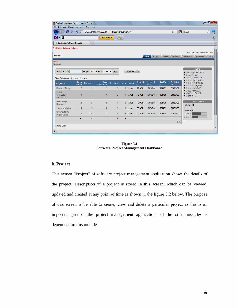
58
Figure 5.1 Software Project Management Dashboard
b. Project
This screen “Project” of software project management application shows the details of
the project. Description of a project is stored in this screen, which can be viewed,
updated and created at any point of time as shown in the figure 5.2 below. The purpose
of this screen is be able to create, view and delete a particular project as this is an
important part of the project management application, all the other modules is
dependent on this module.
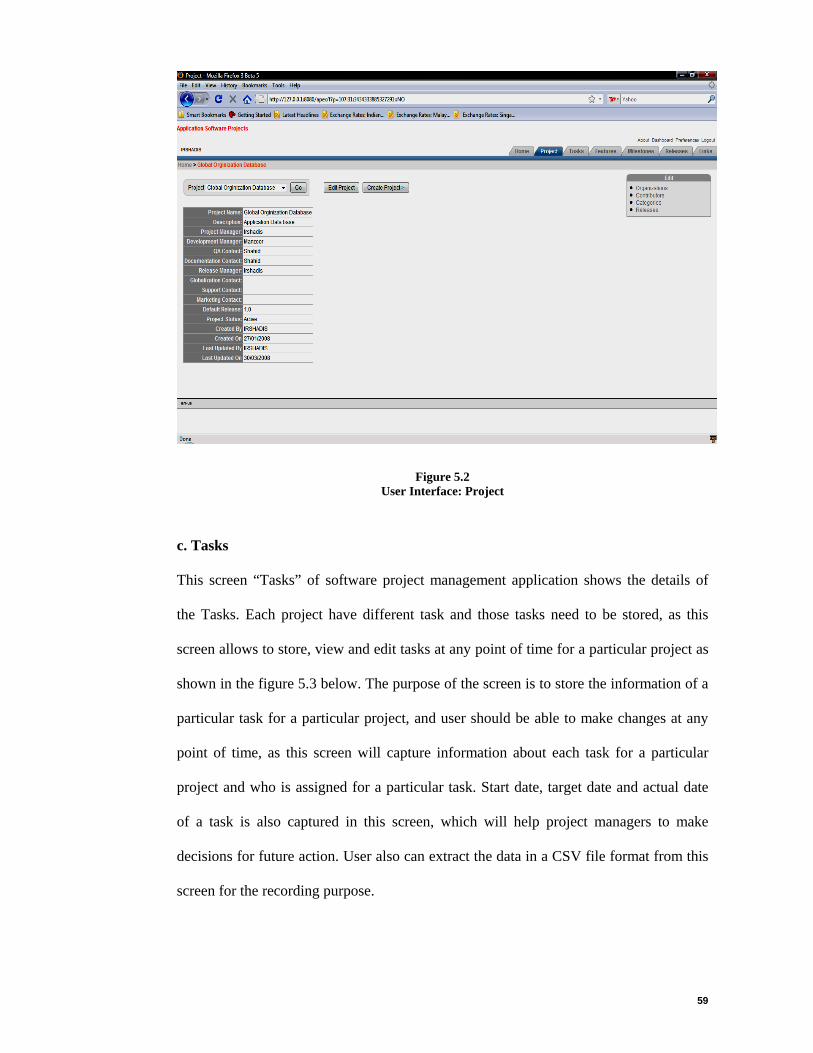
59
Figure 5.2 User Interface: Project
c. Tasks
This screen “Tasks” of software project management application shows the details of
the Tasks. Each project have different task and those tasks need to be stored, as this
screen allows to store, view and edit tasks at any point of time for a particular project as
shown in the figure 5.3 below. The purpose of the screen is to store the information of a
particular task for a particular project, and user should be able to make changes at any
point of time, as this screen will capture information about each task for a particular
project and who is assigned for a particular task. Start date, target date and actual date
of a task is also captured in this screen, which will help project managers to make
decisions for future action. User also can extract the data in a CSV file format from this
screen for the recording purpose.

60
Figure 5.3 User Interface Tasks
d. Features
This screen “Features” of software project management application shows the details of
the features of a particular project. Each project have different features which need to be
stored, as this screen allows to store, view and edit features at any point of time for a
particular project as shown in the figure 5.4 below. The purpose of this screen is to
capture the features of a particular project, as each project will have different features
which need to be capture for the future development purposes by doing so the project
manager will be aware of the feature that have been build.

61
Figure 5.4 User Interface Features
e. Milestone
This screen “Milestone” of software project management application shows the details
of the Milestones of a particular project. Each project have different Milestones which
need to be stored, as this screen allows to store, view and edit Milestones at any point of
time for a particular project as shown in the figure 5.5 below. The purpose of this screen
is to capture the milestones of each project so the project will be accomplished on time
or to make discussions if some one misses the milestone. This screen is important as it
capture actual date for each release. This screen also shows the days out for a particular
milestone, it means if the job is not finish on time the screen calculate the number of
days delayed from the actual milestone date, which also will help project manager to
enhance the project plan accordingly. This screen also has a calendar to select from for
a milestone so that user will know about the day and date of a selected milestone.

62
Figure 5.5 User Interface Milestones
f. Releases
This screen “Releases” of software project management application shows the details of
the Releases of a particular project. Each project have different Releases which need to
be stored, as this screen allows to store, view and edit Releases at any point of time for a
particular project as shown in the figure 5.6 below. The purpose of this screen is to
capture the releases of a particular project. This screen will be able to show the release
date, description of a release and number of days that release has been delayed. This
will help project managers to manage the release and keep the project information for
the future planning.

63
Figure 5.6 User Interface Releases
5.3 Software Projects Management Application (SPMA) System Architecture
The selection of system architecture or development approach can be critical in
ensuring that a system will meet changing demands of an organization. The system
architecture for implementing this project is Web based Oracle Apex application
system. The Software Projects Management Application (SPMA) System architecture is
depicted in Figure 5.7

64
Figure 5.7 SPMA Application
Developers: developers are programmers who program or enhance the application
based on the requirements.
Administrators: administrators are the people who administrate and monitor an
application. Administrator has the authority to grant the access to end-users.
End users: end-users those who run the application.
Software Projects Management Application (SPMA) System architecture consists of
Oracle Application Express with oracle database and is comprised of data in tables and
PL/SQL code. Whether anyone is running the oracle application express development
environment or an application anyone built using oracle application express, the process
is the same. Browser sends a URL request that is translated into the appropriate oracle
application express PL/SQL call. After the database processes the PL/SQL, the results
are relayed back to your browser as HTML. The application session state is managed in
the database tables within application express. It does not use a dedicated database
connection. Instead, each request is made through a new database session, consuming
minimal CPU resources.
TCP/IP TCP/IP
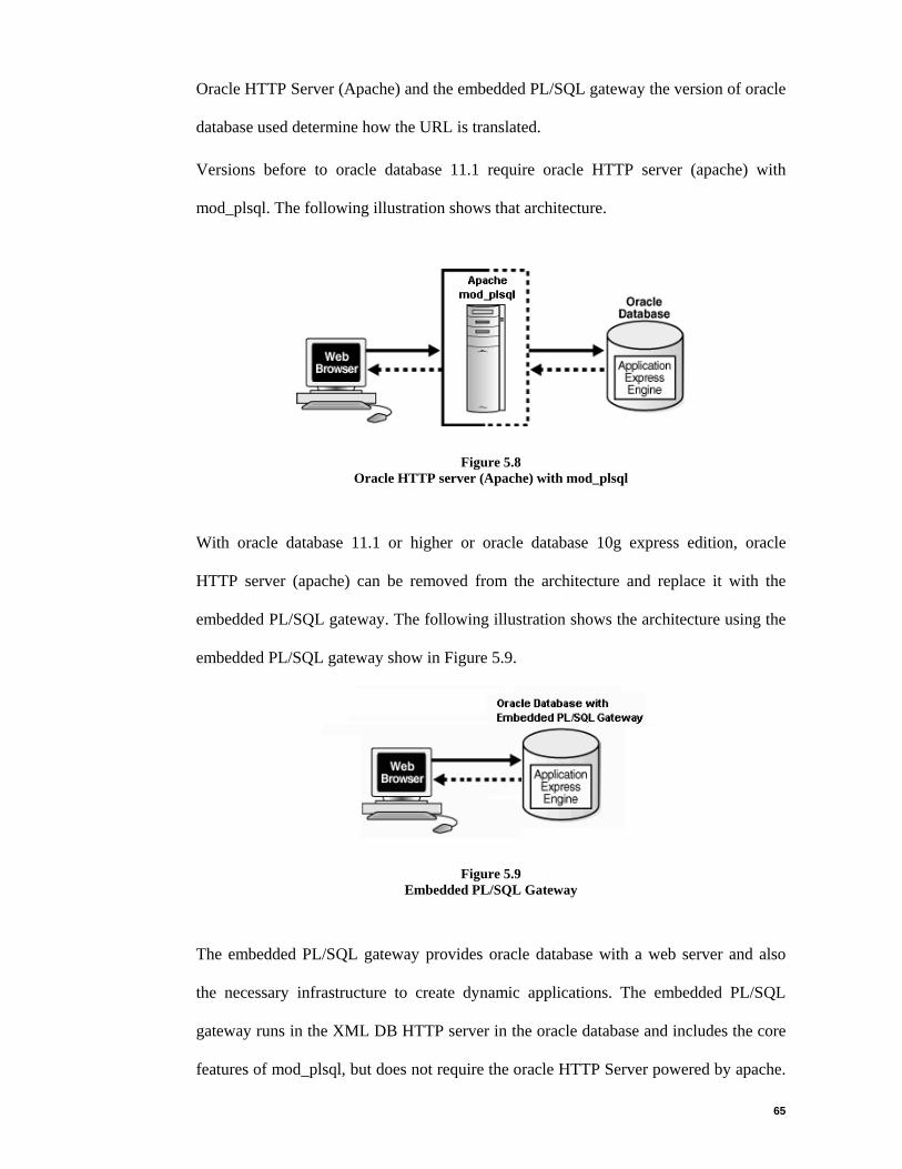
65
Oracle HTTP Server (Apache) and the embedded PL/SQL gateway the version of oracle
database used determine how the URL is translated.
Versions before to oracle database 11.1 require oracle HTTP server (apache) with
mod_plsql. The following illustration shows that architecture.
Figure 5.8 Oracle HTTP server (Apache) with mod_plsql
With oracle database 11.1 or higher or oracle database 10g express edition, oracle
HTTP server (apache) can be removed from the architecture and replace it with the
embedded PL/SQL gateway. The following illustration shows the architecture using the
embedded PL/SQL gateway show in Figure 5.9.
Figure 5.9 Embedded PL/SQL Gateway
The embedded PL/SQL gateway provides oracle database with a web server and also
the necessary infrastructure to create dynamic applications. The embedded PL/SQL
gateway runs in the XML DB HTTP server in the oracle database and includes the core
features of mod_plsql, but does not require the oracle HTTP Server powered by apache.

66
Inclusion of the embedded PL/SQL gateway simplifies the architecture and eliminates
the middle tier. Most common browsers are supported (Microsoft, Netscape, Firefox,
Mozilla). Applications can be developed and run anywhere where there is connectivity.
5.4 Software Projects Management Application (SPMA) Modules
Effective Software project management is central not only to project performance, but
also to performance on the industry level. The principles of project management are
applicable at all levels of the project hierarchy, ranging from individual work packages
through to the provision of a single point of responsibility on behalf of the client.
Different techniques and skills are applicable at different levels. The project manager
who manages the entire project on behalf of the client must be able to co-ordinate teams
of professionals from diverse backgrounds. In figure 5.10 are the following modules of
the web-based software project management system.
Figure 5.10 Software Project Management Modules
Project
Categories Contributor Organization
Releases Milestones Tasks Features
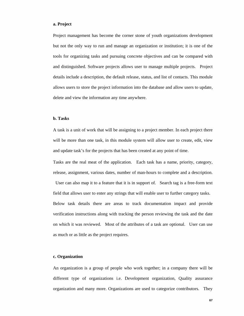
67
a. Project
Project management has become the corner stone of youth organizations development
but not the only way to run and manage an organization or institution; it is one of the
tools for organizing tasks and pursuing concrete objectives and can be compared with
and distinguished. Software projects allows user to manage multiple projects. Project
details include a description, the default release, status, and list of contacts. This module
allows users to store the project information into the database and allow users to update,
delete and view the information any time anywhere.
b. Tasks
A task is a unit of work that will be assigning to a project member. In each project there
will be more than one task, in this module system will allow user to create, edit, view
and update task’s for the projects that has been created at any point of time.
Tasks are the real meat of the application. Each task has a name, priority, category,
release, assignment, various dates, number of man-hours to complete and a description.
User can also map it to a feature that it is in support of. Search tag is a free-form text
field that allows user to enter any strings that will enable user to further category tasks.
Below task details there are areas to track documentation impact and provide
verification instructions along with tracking the person reviewing the task and the date
on which it was reviewed. Most of the attributes of a task are optional. User can use
as much or as little as the project requires.
c. Organization
An organization is a group of people who work together; in a company there will be
different type of organizations i.e. Development organization, Quality assurance
organization and many more. Organizations are used to categorize contributors. They

68
are not specific to a project but used by all projects. This module stores the information
of organization for each task, which can be edited, and view at any time.
d. Contributors
An entity is responsible for making contributions to the content of the resource.
Examples of contributor include a person, an organization, or a service. In each task
there might be different contributors, this module allows user to create and maintain the
contributors that are referenced by the tasks and milestones. Contributors are specific to
a project but for a task, user can enter a person for assigned to or contributor that is not
already defined as a contributor. This module also allows users to stores the information
of each contributor and user will be able to create, view and delete the contributor
depending on the user’s request.
e. Categories
Allows users to create and maintain the categories that are referenced by the tasks.
Categories are specific to a project. Categories answer the question "What is this item or
page" and are used to classify content, for example, sales reports, action items, tasks,
corporate icons and graphics, and location maps are all examples of typical categories.
For every item, tasks or page that user create, user can assign it to one category. The
purpose of categories is to enable users to quickly display a listing of a particular type
of content. Categories are used to organize tasks into logical groups.
f. Features
Features allow user to detail features of an application. Features can then be linked to
tasks to show that a task is in support of a certain feature. Features are hierarchical in
nature and have a status of their own. User can identify the release in which the feature

69
was introduced. That allows user to track the growth of a project or product over time.
If user specifies to publish a feature, it will then be displayed on the Printer Friendly
View. In addition to being mapped to tasks, features can also be mapped to comparison
releases. This allows user to define either releases of a product or a competitive release
and identify how the product compares. When user defines a feature, all the
comparison releases that have been defined for the current project are displayed. User
can either set the availability to yes, no or text. Yes will display a checkbox in the
feature report, no will display a red x and text will display whatever text user enter
under description.
g. Milestones
Milestones are specific to a project and can be associated with a specific release.
Milestones allow user to specify certain events in the project that are not tasks such as
feature complete, ready for internal testing. Milestones display on the tasks calendar
but there is also a specific milestone calendar that displays only milestones for a
selected release.
h. Releases
A release is a group of one or more files that are published as a unit. Each release can
have a maturity level attribute to describe its state of completeness. Maturity levels are
predefined and include development build, alpha, beta, and general availability.
Releases are specific to a Project and allow user to group tasks together. Releases are
especially helpful for projects to develop software. Releases allow user to define
iterative releases and then track tasks and features against those releases.

70
5.5 Product Perspective
The “Software Projects Management Application” will be developed in oracle apex.
This tool is an oracle scaled down version of oracle portal. It's a powerful and easy way
to quickly develop a database-centric HTML web application. It is easy enough to use
that “power users” can develop smaller user-friendly applications, and full time
developers can create some very impressive applications.
Oracle application express is a rapid web application development tool for the oracle
database. Using only a web browser and limited programming experience, professional
applications can develop that are both fast and secure. Thanks to built-in features such
as user interface themes, navigational controls, form handlers, and flexible reports,
oracle application express accelerates the application development process. From the
end user's perspective, the deployed applications require only a browser and access to
an oracle database running application express.
5.6 Testing
Testing is finding out how well application works. In software development, testing is
used at key checkpoints in the overall process to determine whether objectives are being
met. The testing process is often divided into different levels or phases to make the
whole process more manageable. These levels are designed to build upon each other,
making the discovery of errors easier by first testing the application in smaller and less
complex pieces. It is quite common to partition the testing process into the following
phases:
• Unit testing
• Integration testing
• System testing

71
The above phases were being used to fulfill requirements of this proposed system in
which unit testing and integration testing was done during development phase of the
system, as it was easy for developer to rectify the errors and fix those errors at the same
time. System testing was done on the basis of the test scripts shown in table 5.1 and
table 5.2. The entire test script were tested and completed which is further discussed in
this chapter.
5.6.1 Test Cases
Authenticate User
System should allow login only valid users, if user does not enter valid user name and
password system should prompt error. Test result shown in Fig 5.11 below:
Invalid User
If a user keys in wrong user name or password the system will prompt an error as
shown in the figure 5.11.
Figure 5.11 Invalid User
Invalid user name/password

72
Valid User
Once the user us valid the main screen “Home” of the application will be displayed with
all the project that have been created in the system with their related information.
Figure 5.12 Valid User
As in above figure 5.12 shows the details of the each project stored in the software
project management application and on the right side of the screen it displays the task
related to a project which a user can click and update on any point of time. This screen
also shows what is the current release of a project. Test case scripts that system should
able to perform are in the table 5.1 and table 5.2.
This is the main screen after Successful login Here new project can be created or edited.

73
Table 5.1 Test Case Scripts
PROJECT TASK FEATURES
Create
System should be able to create a Project and user should be able to insert the details of the project.
System should be able to create a task and user should be able to insert and assign the details of the task to staff.
System should be able to create the features of the each project.
Edit Details
User should be able to update the project details at any point of time.
User should be able to update the task details at any point of time.
User should be able to update the details of the features of the each project at any point of time.
View Details
User should be able to see all the details of the project.
User should be able to see all the details of the task.
User should be able to see all the details of the features of the each project.
Delete User should be able to delete a project.
User should be able to delete a task.
User should be able to delete the features of each project.
Table 5.2 Test Case Scripts-Cont
MILESTONE RELEASES LINKS
Create
System should be able to create a Milestone and user should be able to insert the details of the milestone for a project.
System should be able to create the release of a project and should be able to record the details of the releases for each project.
System should be able to create the links of the each project.
Edit Details
User should be able to update the milestone details at any point of time.
User should be able to update the releases details at any point of time.
User should be able to update the details of the links of each project at any point of time.
View Details
User should be able to see all the details of the milestone.
User should be able to see all the details of the releases.
User should be able to see all the details of the links of each project.
Delete User should be able to delete a milestone.
User should be able to delete releases for the projects.
User should be able to delete the links of each project.

74
Refer to appendix e-application test results and GUI for the test result screen shots.
Once the entire system is validated, it must be combined with other system element
such as hardware, end-user and databases. System testing verifies that elements are
functioning properly and the overall system performance and objectives are achieved
which in this case, software projects management application (SPMA) must achieve
reliability, robustness, accuracy, flexibility and modularity.
5.7 Conclusion
This chapter presents system prototype of Software project management application.
System architecture and product perspective are discussed in this chapter. Each modules
of software project management application has been explained to understand the
system prototype. Test case scripts were also been presented in this chapter for the
testing purpose. The next chapter will discuss evaluation of test result of the system
based on the test scripts.
.

75
6.0 CHAPTER 6 - EVALUATION AND CONCLUSION
6.1 Introduction
This chapter concludes the thesis by determining how the developed tool fulfilled the
objectives and the aim. After the fulfillment of objectives and aim section, the conclusion
section presents the significance and contribution of this thesis. This chapter will end
pointing out the future directions of work related to the studies on the software project
planning automation support.
6.2 User Evaluation
System test was carried out to get the user’s evaluation on the developed system. This is to
ensure that the system has met the user’s requirement. In order to get user’s evaluation and
perception on the system, an evaluation form is produced with several questions (see in
appendix f), which the purpose is to get user’s information on particular part. The results of
the evaluation are shown from figure 6.1 to figure 6.12 in this chapter.
6.2.1 System Functionalities
This section discussed the result obtained from the major functionality test (i.e. Create,
Delete and Update a project, task, milestone and releases which is shown below from figure
6.1 to figure 6.6) and evaluation form, which focused on functionalities of the system.
Below Figure 6.1 shows the percentage of user’s evaluation on the software projects
management application (SPMA) to create, delete and update a project through the
application.
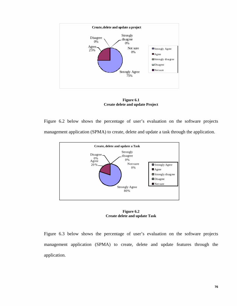
76
Strongly Agree75%
Agree25%
Strongly disagree
0%Disagree
0%
Not sure0%
Create, delete and update a project
Strongly Agree
Agree
Strongly di sa gree
Disagree
Not sure
Figure 6.1 Create delete and update Project
Figure 6.2 below shows the percentage of user’s evaluation on the software projects
management application (SPMA) to create, delete and update a task through the application.
Strongly Agree80%
Agree20 %
Strongly disagree
0%Disagree
0%
Not sure0%
Create, delete and update a Task
Strongly AgreeAgree
Strongly disagreeDisagree
Not sure
Figure 6.2 Create delete and update Task
Figure 6.3 below shows the percentage of user’s evaluation on the software projects
management application (SPMA) to create, delete and update features through the
application.

77
Strongly Agree60%
Agree40%
Strongly disagree
0%Disagree
0%Not sure
0%
Create, delete and update Features
Strongly AgreeAgreeStrongly disagreeDisagreeNot sure
Figure 6.3 Create delete and update Features
Figure 6.4 below shows the percentage of user’s evaluation on the software projects
management application (SPMA) to create, delete and update a milestone through the
application.
Strongly Agree60%
Agree40%
Strongly disagree
0%Disagree
0%
Not sure0%
Create, delete and update a Milestone
Strongly Agree
Agree
Strongly disagree
Disagree
Not sure
Figure 6.4 Create delete and update Milestone
Figure 6.5 below shows the percentage of user’s evaluation on the software projects
management application (SPMA) to create, delete and update releases through the
application.
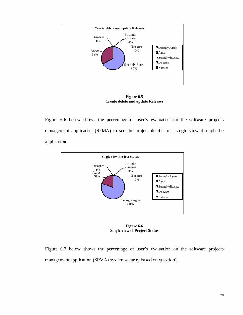
78
Strongly Agree67%
Agree33%
Strongly disagree
0%Disagree
0%
Not sure0%
Create, delete and update Releases
Strongly AgreeAgree
Strongly disagree
Disagree
Not sure
Figure 6.5 Create delete and update Releases
Figure 6.6 below shows the percentage of user’s evaluation on the software projects
management application (SPMA) to see the project details in a single view through the
application.
Strongly Agree80%
Agree20%
Strongly disagree
0%Disagree
0%
Not sure0%
Single view Project Status
Strongly Agree
Agree
Strongly disagree
Disagree
Not sure
Figure 6.6 Single view of Project Status
Figure 6.7 below shows the percentage of user’s evaluation on the software projects
management application (SPMA) system security based on question1.
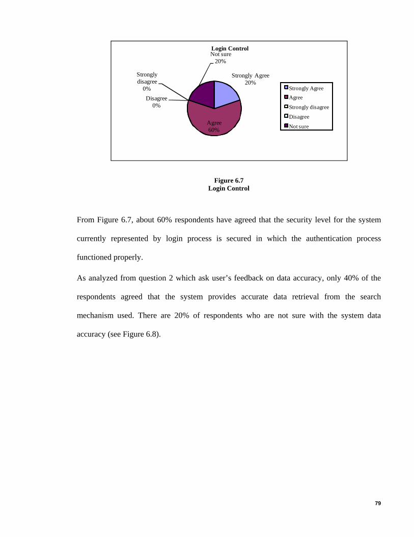
79
Strongly Agree20%
Agree60%
Strongly disagree
0%Disagree
0%
Not sure20%
Login Control
Strongly AgreeAgree
Strongly disagree
Disagree
Not sure
Figure 6.7 Login Control
From Figure 6.7, about 60% respondents have agreed that the security level for the system
currently represented by login process is secured in which the authentication process
functioned properly.
As analyzed from question 2 which ask user’s feedback on data accuracy, only 40% of the
respondents agreed that the system provides accurate data retrieval from the search
mechanism used. There are 20% of respondents who are not sure with the system data
accuracy (see Figure 6.8).
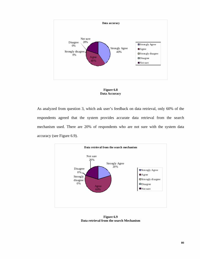
80
Strongly Agree40%
Agree40%
Strongly disagree0%
Disagree0%
Not sure20%
Data accuracy
Strongly Agree
Agree
Strongly disagree
Disagree
Not sure
Figure 6.8 Data Accuracy
As analyzed from question 3, which ask user’s feedback on data retrieval, only 60% of the
respondents agreed that the system provides accurate data retrieval from the search
mechanism used. There are 20% of respondents who are not sure with the system data
accuracy (see Figure 6.9).
Strongly Agree20%
Agree60%
Strongly disagree
0%
Disagree0%
Not sure20%
Data retrieval from the search mechanism
Stro ngly Agree
Agree
Stro ngly disagree
Disagree
Not sure
Figure 6.9 Data retrieval from the search Mechanism

81
Question 4, from the evaluation form focused on system effectiveness. Figure 6.10 shows a
pie chart contains percentage of user’s feedback on the system effectiveness. About 60% of
the respondents agreed that Software Projects Management Application (SPMA) system
provides functions that increase the effectiveness in achieving its development objectives.
However, 20% respondents are not sure with the system’s effectiveness.
Strongly Agree20%
Agree60%
Strongly disagree
0%
Disagree0%
Not sure20%
Effectiveness in achieving its objectives.
Strongly Agree
Agree
Strongly disagree
Disagree
Not sure
Figure 6.10 Effectiveness in achieving its Objectives
As analyzed from question 5, which ask user’s feedback on system response, only 60% of
the respondents agreed that the system response is fast (see Figure 6.11).

82
Strongly Agree40%
Agree60%
Strongly disagree
0%
Disagree0%
Not sure0%
System response time
Strongly AgreeAgreeStrongly disagreeDisagreeNot sure
Figure 6.11 System response Time
As analyzed from question 6, which ask user’s feedback on data reporting, only 60% of the
respondents agreed that the system provides accurate reporting. There are 20% of
respondents who are not sure with the system reporting (see Figure 6.12).
System reporting generation
Strongly Agree20%
Agree60%
Disagree0%
Not sure20%
Strongly disagree0%
Strongly AgreeAgreeStrongly disagreeDisagreeNot sure
Figure 6.12 System reporting Generation

83
6.3 Comparison with Existing System
As far as current system in Longbridge Consulting Sdn.Bhd is concerned the project details
are captured on excel sheets and data is inserted and update by the users, as there are more
than one sheet ‘s for each project, which is not efficient to handle and manage. Below in
Table 6.1 is the comparison between new and existing system.
Table 6.1 Comparison between new and Existing System
Software Projects Management Application (SPMA) Longbridge Current System
Data will be inserted and saved in the database through different Screen, which will be available online for everyone.
Data is inserted in excel sheets, and reside in one place.
Single view if the project status.
No single view available. User needs to view different sheet of a project.
Accessed By Multi User at any point of time. Only one user can access at a single point of time.
Easy to manage. Difficult to manage as the project grows excel sheet grows as well.
Faster data retrieval and better search options. Time consuming.
More than one person can update Project details.
The organization will have to rely on one person to do updating
Everyone can have full picture of the project and will know status of each member.
Top management does not have the full picture of the project and does not know what each team member is busy with
All projects information is located in database and is available every time.
Users always need to remember where the correct file is located.
84
6.4 System Strength
Software projects management application (SPMA) Tool is a distributed project planning
tool that enables more than a single person to prepare the different parts of the project scope,
schedule and task assignment by allowing the use of the predefined organizational level
activities and enabling the effective use of the project information through the project life
cycle.
The strengths of software projects management application (SPMA) as a project
management system are identified as follows:
• The software projects management application (SPMA) web-based system helps
project managers to access from anywhere in the world.
• The software projects management application (SPMA) web-based system allows
user to manage multiple projects at any point of time.
• Using oracle tool called oracle application express for this system as it is
integrated with the database schema and internal DBMS structures, which offers
reliability and faster response for any request from the application.
• Providing over all single view of the projects on its dashboard, which is good for
the project managers to track the project status.
• The software projects management application (SPMA) web-based system has
ability to assign tasks to a team or one or more project members.
• Reports can be generated straight away to .CSV files without having any
supportive tool.
• Using oracle application express for this system, which is a more reliable, secure,
and scalable alternative to spreadsheets and desktop databases.
In table 6.2 shows how the current problem has been solved.

85
Table 6.2
How Problem Solved
Current Problems How current problem solved
Difficulty in achieving the required efficiency in their projects
The system will provide a single view of the projects details, as it is better for a project manager to see where and how the project is going ahead and project managers can make the changes if necessary to achieve the efficiency.
Difficulty in keeping track of their employee tasks in real time.
Each task will be recorded in the system and a person will be assigned to a particular task of a particular project so that it will be easier for managers to keep track of their tasks and the people assigned to each task in real time.
Difficulty in keeping track of the overall project completion status.
A single view details of a particular project will be shown on the dash board and all the information like open tasks, milestones, releases etc will be shown, so that it will help managers to see the project overall status.
Unable to meet planned Milestone due to unplanned problems arising.
Milestones for a particular project will be defined in the system according to the other important information like tasks, features etc, been recorded down. This will help managers to see where they are behind if they are unable to meet the milestone of a particular project.
Difficult to keep track of new features implemented.
Each features implemented will be recorded down in the system for a particular project and will be shown at any point of time.
Difficult to keep track of new releases of the software product.
Each new release will be recorded done for a particular project and will be shown at any point of time.
Hassle for project managers to prepare reports on project tasks and milestones.
By a click reports will be generated for project managers as the information is already been recorded down in the system for a particular project.

86
6.5 Limitations
No one can doubt that project management software is a great tool to help project managers
save a significant amount of time. However, the tremendous power of project management
software can break project manager into a false sense of security (Heerkens, 2002). As every
other software, applications like MS Project are just tools; they do not execute the entire job
for the project managers. It is unacceptable to expect a computer to manage the project; it
just manages the amount of data that projects require to store (Verzuh, 2003). Project
management software is incapable of establishing project objectives, define project tasks or
dependencies, determine and manage project constraints (Richman, 2002). However,
software does not replace the delicate skills of an experienced project management, which
can use his experience and talent to lead a project towards a successful closure.
As oracle apex also named as oracle XE is used in this project and it has some limitations.
Oracle XE is free but oracle has built certain limitations into the product. The first limitation
is memory. Oracle database XE can address only 1GB of RAM. This limitation mainly
affects how many users can access the database concurrently and how well it performs. The
second limit is that XE will only use one CPU. XE will run on a multi-CPU computer but
won't scale up to use those CPUs. This functionality requires oracle database standard edition
or enterprise edition. The third limit is that only a single XE database can run on any given
computer. One does not need a database for each application. Instead, oracle uses the concept
of schemas to separate applications. Finally, a 4GB limit is enforced on disk space. 4GB is a
huge amount of storage for most applications.

87
6.6 Future Directions of Work
This study results in a tool that satisfies the basic requirements of automated support for the
software project planning process and provides some facilities for practical use of
organizational level information. The tool may be improved in aspect of sharing project
documents by integrating with the commonly used Configuration Management tools.
Moreover in the organizational level, improvement to provide more detailed activity
structure for the purpose of utilizing in the project schedule preparation may be performed.
• Notify all members who have been assigned if a new project schedule is created
or updated via E-mail or SMS.
• Every week the system should send reminder for only those members who’s due
date of their task is going to end.
• Every month Email should be send by the system to the Project Manager about
the project status.
• User should be able to record the errors to the system from their respective places
if they encounter any error during the application run.
6.7 Contributions
The main objectives of this thesis are to highlight the reasons for delays and incompleteness
in software projects and to minimize them, attempt to reduce complexity and ensure project
quality throughout SPMA development. Therefore the following are the main research
contributions.
a) The need for project management tool to manage software projects: This tool
may consider software project management tool specifically for software projects.

88
b) Managing human resources: SPMA helps project managers reduce delays and
ensure project quality by providing the necessary information. These features can
save a lot of time and moderate making decision, and ensures quality.
c) Reduce problems and prevent the managers from making mistakes: The tool
helps to minimize the problems that the other projects have faced. This is done by
analyzing the problems in past projects and comparing the problems in some selected
projects and addressing the problems due to change in requirements.
d) Technology issue: Provides reports about the latest information, updated versions of
the available software and these results would enormously help in saving time and
effort for searching on the needed equipment and it helps to accurately estimate the
project.
6.8 Conclusion
This thesis focused on the project management application to support project managers for
their project planning. The application was developed with the intention to overcome the
issues faced by the project managers during software development.
“Software Projects Management Application” makes a valuable contribution to project
planning process. The “Software Projects Management Application” comprises more
extensive capabilities. Therefore, this thesis is a significant study because of its contribution
to reveal the deficiencies of existing project planning tools in aspect of collaborative
preparation of project plan and utilizing the organizational information. As a conclusion, this
thesis may be a reference to improve the capabilities of project planning tools. This thesis
has represented the implementation of web based software project management application
for project managers for planning software projects.

89
REFERENCES
Abu Bakar, Z. , Baharum, N. , Haji Yaacob, M. (2001) Systems Integration and Project
Management. Malaysian Journal of Computer 14(1). 9-15
Deek, F.P. (1997). An Integrated Environment for Problem Solving and Program
Development, Newark, NJ, USA: New Jersey Institute of Technology.
Deek, F. P. (1999). The Software Process: A Parallel Approach through Problem Solving
and Program Development. Computer Science Education, 9(1), 43-70.
Deek, F.P., Hiltz, S.R., Kimmel, H., Rotter, N. (1999). Cognitive Assessment of Students,
Problem Solving and Program Development Skills. Engineering Education, 88(3). 317-326.
Friedlein, A. (2001). Web Project Management: Delivering Successful Commercial. CA: San
Francisco: Morgan Kaufmann.
Fuller, J. (1997). Managing Performance Improvement Projects. CA: San Francisco:
Pfeiffer.
Heerkens G, 2002. Project Management, USA: McGraw-Hill. 138
Hughes, B, and Cotterell, M. 2006. Software Project Management. Fourth Edition. London:
McGraw-Hill. ISBN 10-0077-109899. 356.
Ibrahim, H. (2001). Deriving Global and Local Integrity Rules for a Distributed Database.
Malaysian Journal of Computer Science 14(2). 70-80.
John W. Satzinger, Robert Jackson, and Stephen D. Burd. (2004) System Analysis and
Design in a changing world, 3rd edn. Boston, MA: United States Course technology press.

90
Kathleen, P., Berkun, S. (2005). Art of Project Management: Software Productivity Centre
Inc. (SPC) in Vancouver, Software Project Estimation. Cambridge: MA: O'Reilly Media.
(ISBN 0-596-00786-8), Canada: British Columbia.
McConnell, S. (1996). Rapid development, taming wild software schedules,
1st edn. Washington: Microsoft press.
Nunamaker, J. (1999). Collaborative Computing, The Next Millennium Computer, 32(9).
66-71.
Post, G.V.( 1999) Database Management Systems. England: Irwin/McGraw-Hill, (ISBN
0072898933, 157-71).
Poppendieck, T and Poppendieck, M (2003). Lean Software Development: An Agile Toolkit
for Software Development Managers, Boston MA, (ISBN 0-321-15078-3): Addison-Wesley.
Prey, J.C. (1996). Cooperative learning and closed laboratories in an undergraduate
Computer Science curriculum, Proceeding of Integrating Technology into Computer Science
education, Spain: 23-24.
Richman L, 2002, Project Management Step-by-Step, USA: AMACOM. 93.
Sayed, A. Md. ,Hoque ,L. , Arefin, S.M. (2009) Multilingual Data Management In Database
Environment. Malaysian Journal of Computer 22(1). 44-63.
Schwalbe, K.2006. Information Technology Project Management, Canada: Thomson Course
Technology.
Standish (2009) “Chaos Report”, summarizing survey Available Online:
http://ezinearticles.com/?The-Curious-Case-of-the-CHAOS-Report-2009&id=2412575
91
Sukhoo, A., Barnard A., Mariki M. Eloff, and John A. Van der Poll (2007) An Evolutionary
Software Project Management Maturity Model for Mauritius Interdisciplinary Journal of
Information, Knowledge, and Management, University of South Africa, Pretoria, South
Africa, 2(1). 99-118
Thomas, S. R., Tucker, R.L., and Xiaoyi Dai, C. (1999). Compass: An assessment tool for
improving project team communications. Project Management Journal, 30(1). 15-24.
Turner, R. J. (1999) The Handbook of Project-Based Management. 2nd edition, England:
McGraw-Hill.
Verzuh E, 2003, The Portable MBA in Project Management, USA: John Wiley & Sons. 104.
Wilson, J., Hoskin, N., Nosek, J. (1993). The Benefits of Collaboration for Student
Programmers, 24th SIGCSE technical symposium on Computer Science Education.160-164.
Yuhanna, N., Daniels.M (2006). Oracle Application Express Helps Build Web Applications
Quickly. USA: Cambridge. 1(1) 1-5.
Lorenzen, P. (2007). Oracle Application Express. ODTUG Technical Journal second
quarter. Denmark. 2(1) 1-13.

92
APPENDIX A – INTERVIEW QUESTIONNAIRE
Interview Questions:
Software Project Management Application Survey: Name : Age : Occupation : Q1: Does your company currently use any project management software Tool? A). Yes B). No If “Yes” please name the program: ______________________________________ If “No” Please indicate (tick) the reason/s for NOT using project management software tool (more than one can be chose): Cost ________ Difficulty of use ________ Limitations of software ________ Not necessary ________ Others please Specify: ____________________________________________ Q2: Are you happy with your current project management software Tool? A). Yes B). No If “No” Please indicate (tick) the reason/s for NOT using project management software tool (more than one can be chose):
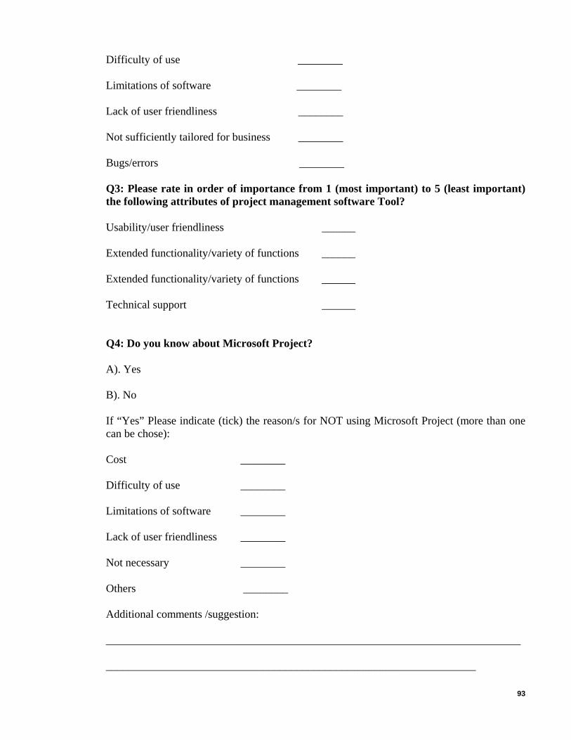
93
Difficulty of use ________ Limitations of software ________ Lack of user friendliness ________ Not sufficiently tailored for business ________ Bugs/errors ________ Q3: Please rate in order of importance from 1 (most important) to 5 (least important) the following attributes of project management software Tool? Usability/user friendliness ______ Extended functionality/variety of functions ______ Extended functionality/variety of functions ______ Technical support ______ Q4: Do you know about Microsoft Project? A). Yes B). No If “Yes” Please indicate (tick) the reason/s for NOT using Microsoft Project (more than one can be chose): Cost ________ Difficulty of use ________ Limitations of software ________ Lack of user friendliness ________ Not necessary ________ Others ________ Additional comments /suggestion:
__________________________________________________________________________
__________________________________________________________________
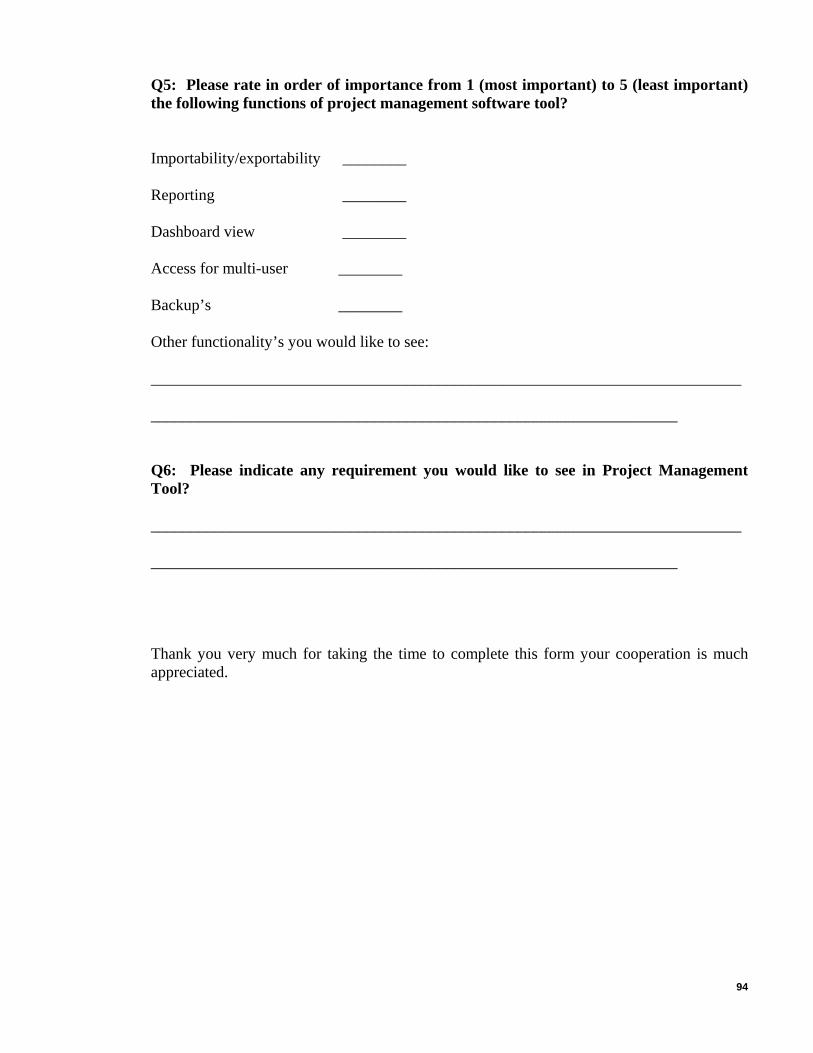
94
Q5: Please rate in order of importance from 1 (most important) to 5 (least important) the following functions of project management software tool? Importability/exportability ________ Reporting ________ Dashboard view ________ Access for multi-user ________ Backup’s ________ Other functionality’s you would like to see: __________________________________________________________________________
__________________________________________________________________
Q6: Please indicate any requirement you would like to see in Project Management Tool? __________________________________________________________________________
__________________________________________________________________
Thank you very much for taking the time to complete this form your cooperation is much appreciated.
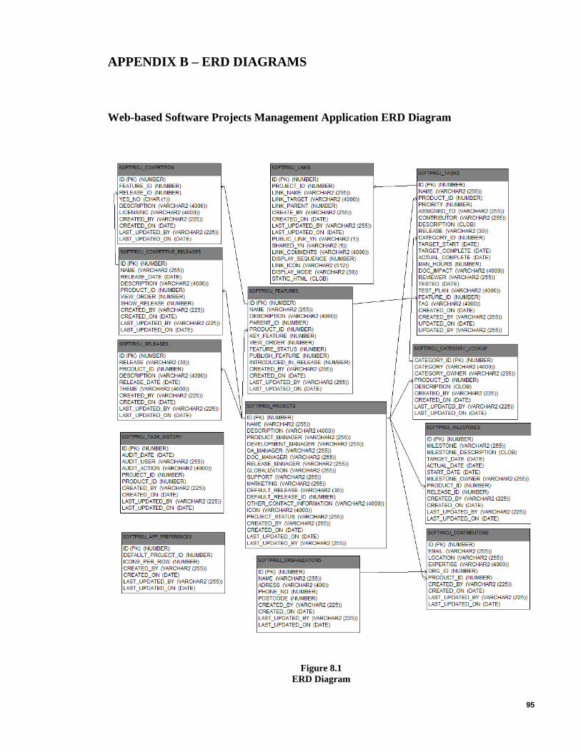
95
APPENDIX B – ERD DIAGRAMS
Web-based Software Projects Management Application ERD Diagram
Figure 8.1 ERD Diagram

96
APPENDIX C – DFD DIAGRAMS
Create Project
D4 Tb Project
Record set
Insert Query
1.2 Update Project
Project Information
System Administrator
Project Information 1.1
Create Project
Record set Update Succeed/Failed Message
Delete Query
Create Succeed/Failed Message
Update Query
Record set
1.3 Delete Project
View Query
Record set View Project Result
Project Information
Search Query 1.5
Search Project
View Project Result
Project Information
Project Information
1.4 View
Project
Record set
Project Search Results
Project Information
Delete Succeed/Failed Message
User
Project Search Results
Project Information
Figure 9.1 Create Project

97
Create Task
Task Information Insert Query System
Administrator Create Succeed/Failed Message Record set
Task Information
2.1 Create Task
D4 Tb Tasks Update Query
Record set
2.2 Update Task
View Task Result
Task Information 2.4
View Task
View Query
Update Succeed/Failed Message
2.3 Delete Task
Task Information Delete Query
Record set
Record set
View Task Result
Task Search Results
Task Information
Delete Succeed/Failed Message
Task Information
Search Query
Record set Task Search Results
2.5 Search Task
User Task Information
Figure 9.2 Create Task
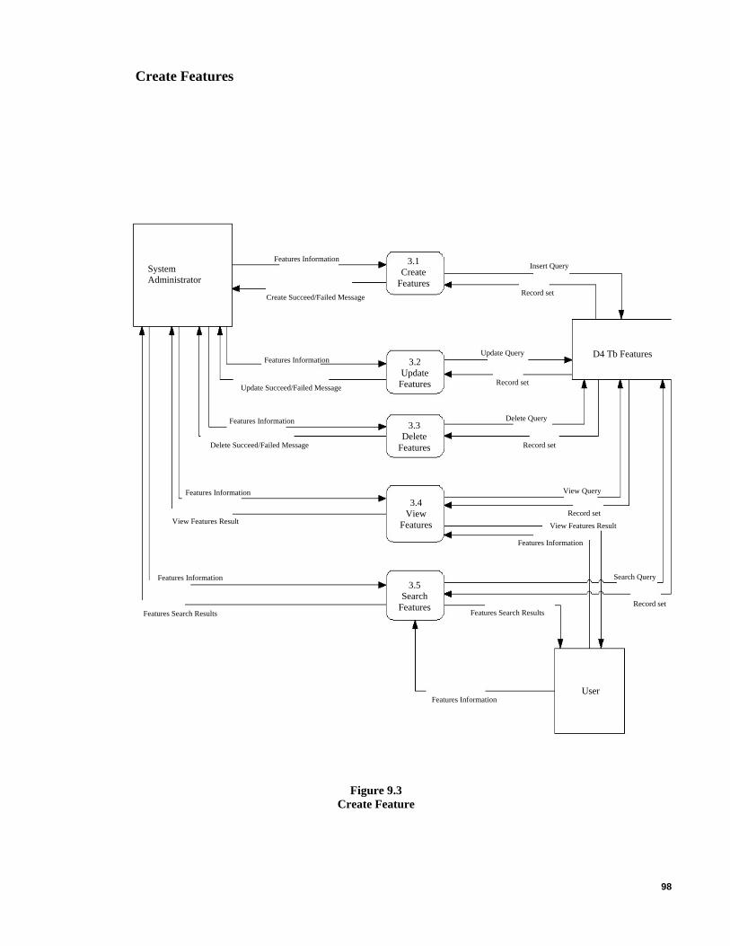
98
Create Features
3.1 Create
Features
Features Information Insert Query System
Administrator
D4 Tb Features
Create Succeed/Failed Message Record set
Update Query 3.2
Update Features
3.3 Delete
Features
Update Succeed/Failed Message
Delete Query
Record set
Features Information
Features Information
Record set Delete Succeed/Failed Message
3.4 View
Features
Features Information
View Features Result
View Query
Record set View Features Result
Features Information
Features Search Results Features Search Results
3.5 Search
Features
Features Information
Record set
Search Query
Features Information User
Figure 9.3 Create Feature

99
Create Milestones
4.1 Create
Milestone
Milestone Information
System Administrator
Insert Query
D4 Tb Milestone
Create Succeed/Failed Message Record set
Milestone Information
Milestone Information 4.3
Delete Milestone Record set
Update Query
Update Succeed/Failed Message
Delete Query
Delete Succeed/Failed Message
Milestone Information
Record set
4.2 Update
Milestone
View Project Result
4.4 View
Milestone
View Query
Milestone Information
Milestone Search Results
4.5 Search
Milestone
Search Query
Milestone Information
View Milestone Result Record set
Milestone Search Results
Record set
User Milestone Information
Figure 9.4 Create Milestone

100
Create Releases
Releases Information 5.1
Create Release
Record set
Insert Query System
Administrator
Record set
Create Succeed/Failed Message
Update Query Releases Information
5.3 Delete Release
Releases Information
D4 Tb Releases
Update Succeed/Failed Message
Delete Query
Delete Succeed/Failed Message
5.4 View
Release
Releases Information
View Releases Result
Releases Information
Releases Search Results
Releases Information
Record set View Releases Result
View Query
5.2 Update Release
Record set
5.5 Search Release Record set
Releases Search Results
Search Query
Releases Information User
Figure 9.5 Create Releases
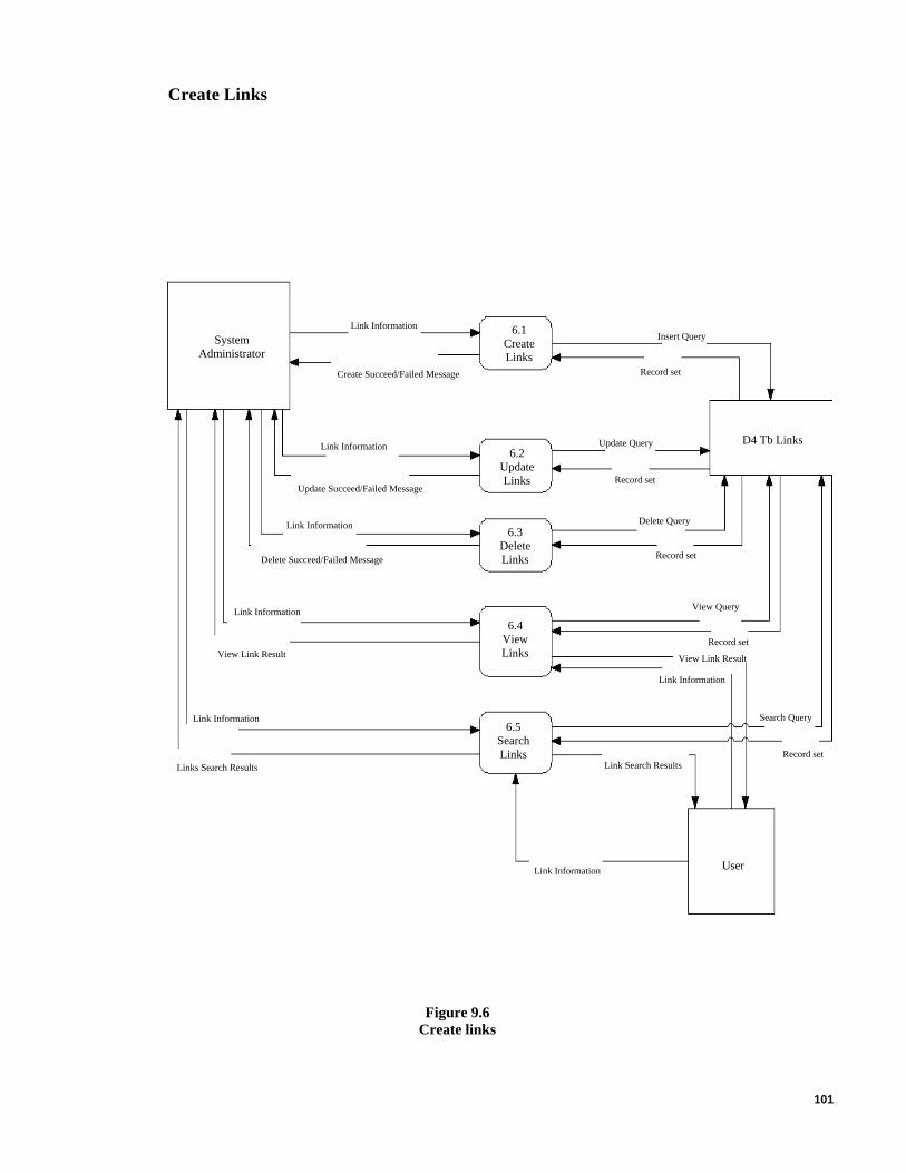
101
Create Links
6.1 Create Links
Link Information System
Administrator Insert Query
Create Succeed/Failed Message Record set
D4 Tb Links Update Query
Record set
Delete Query
6.2 Update Links
Link Information
Record set
View Query
View Link Result
Link Information
Search Query
Link Search Results
6.3 Delete Links
Update Succeed/Failed Message
Link Information
Record set
Record set
6.4 View Links
Delete Succeed/Failed Message
Link Information
View Link Result
User Link Information
Link Information
Links Search Results
6.5 Search Links
Figure 9.6 Create links
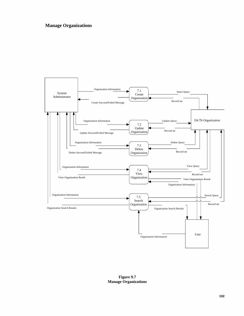
102
Manage Organizations
Insert Query 7.1 Create
Organization
Organization Information System
Administrator Record set
D4 Tb Organization
Create Succeed/Failed Message
Record set
Update Query 7.2
Update Organization
7.3 Delete
Organization
Organization Information
Organization Information
Record set
Delete Query
View Query
Record set
View Organization Result
Organization Information
7.4 View
Organization
Update Succeed/Failed Message
Delete Succeed/Failed Message
Search Query
Record set
Organization Search Results
Organization Information
View Organization Result
User
Organization Information
Organization Search Results
7.5 Search
Organization
Organization Information
Figure 9.7 Manage Organizations

103
Manage Contributors
Contributor Information Insert Query 8.1
Create Contributor
8.2 Update
Contributor
System Administrator
D4 Tb Contributors
Delete Query
Update Query
Record set Create Succeed/Failed Message
Contributor Information
View Contributor Result
Record set
View Query
Record set
8.4 View
Contributor
Update Succeed/Failed Message
Contributor Information
Record set Delete Succeed/Failed Message
Contributor Information
View Contributor Result
8.3 Delete
Contributor
Record set Contributor Search Results
Search Query
Contributor Information
8.5 Search
Contributor
Contributor Information
Contributor Search Results
User Contributor Information
Figure 9.8 Manage Contributors

104
Manage Categories
Insert Query 9.1 Create
Category
Category Information System
Administrator
Update Query
Record set
9.2 Update
Category
Create Succeed/Failed Message
Category Information
Update Succeed/Failed Message Record set
D4 Tb Categories
9.3 Delete
Category
9.4 View
Category
Category Information
Delete Succeed/Failed Message
Category Information
View Category Result
Delete Query
9.5 Search
Category
Category Information
Category Search Results
View Query
Record set
View Category Result
Record set
Search Query
Category Information
Category Search Results Record set
User Category Information
Figure 9.9 Manage Categories

105
APPENDIX D – DETAILED DFD DIAGRAMS
Create Project
Administrator 1.1.1
Validate Input
Validation Successful
Create Project Create Project
1.1.2 Get Input
User
Input passed
1.1.3 Connect to DB
Successful”” Message
1.1.4 Insert Project
Failed”” Message
DB connection Successful
Return DB Connection Request DB
Connection
1.1.5 Close DB
Received successfully
Send Record set Create Project
Query DB Connection
failed
Project created Successful
Validation failed
D2 Tb Project
Failed to close DB
Successful”” Message
Project Failed
1.1.6 Display Message
Figure 10.1 Create Project
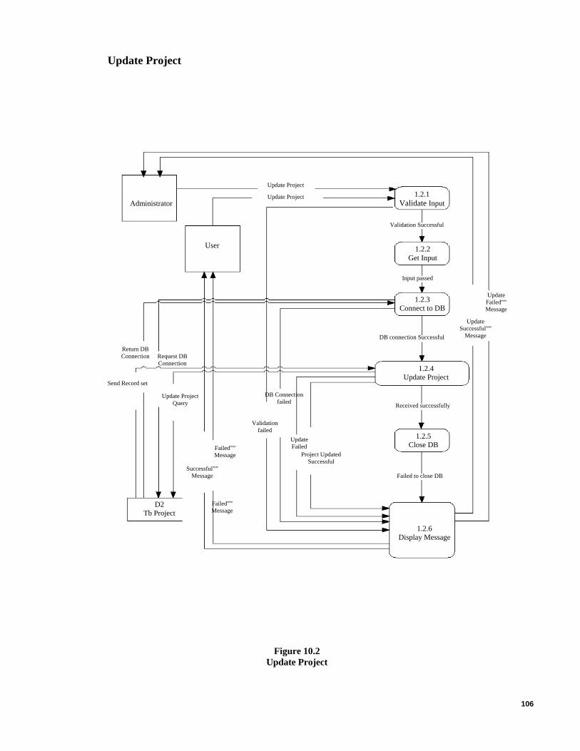
106
Update Project
Failed”” Message
1.2.2 Get Input
Update Project
Update Project 1.2.1 Validate Input Administrator
Validation Successful
User
Input passed
Update Failed”” Message
1.2.3 Connect to DB
Update Successful””
Message DB connection Successful
Send Record set
Update Project Query
DB Connection failed
1.2.4 Update Project
Received successfully
1.2.5 Close DB Failed””
Message
Return DB Connection Request DB
Connection
Validation failed
Project Updated Successful
Update Failed
Successful”” Message Failed to close DB
D2 Tb Project
1.2.6 Display Message
Figure 10.2 Update Project

107
Delete Project
Administrator Delete Project 1.3.1
Validate Input
Validation Successful
User 1.3.2 Get Input
Input passed
Delete Failed””Message
1.3.3 Connect To DB
DB connection Successful
1.3.4 Delete Project
Delete Project Query
DB Connectionfailed
Validation failed
Received successfully
Delete Successful”” Message
Delete Successful
Delete Failed””Message
Delete failed
1.3.5 Close DB
Failed to close DB
D2 Tb Project
Confirm Dialog–Message Yes/No
Delete Project
Delete Successful”” Message
1.3.6 Display Message
Confirm Dialog– Message Yes/No
Send Record Set
Request DB Connection
Return DB Connection
Figure 10.3 Delete Project

108
View project details
Project Information Result
No Projectinfo Result
Select ProjectSystem Administrator
D2 Tb Project
Pass Inputs
Validation Failed
Project Information Result
1.4.4 Retrieve Project
Information
User
Validation Successful
DB Connection Successful
DB Connection Failed Error Message
No Projectinfo Result
1.4.6 Display Message
View Successful
Received Record set
Return DB Connection
1.4.2 Get Input
View Failed Record set
Error Message
1.4.3 Connect To DB Request DB Connection
View SQL Query
1.4.1 Validate
Input
Select Project
Close DB Connation Failed 1.4.5
Close DB
Figure 10.4 View Project Details
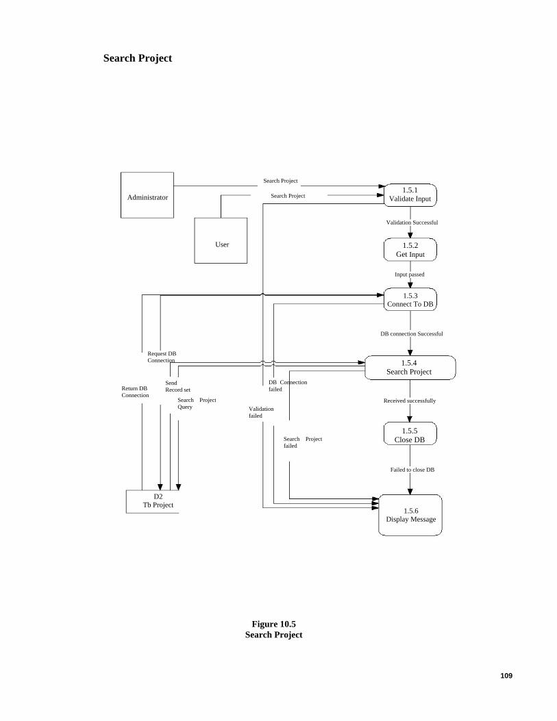
109
Search Project
Administrator 1.5.1
Validate Input
User
Search Project
Search Project
Validation Successful
1.5.2 Get Input
Input passed
1.5.3 Connect To DB
1.5.5 Close DB
DB connection Successful
1.5.4 Search Project
Send Record set
Search Project Query
Request DB Connection
DB Connectionfailed
Search Projectfailed
Validation failed
Return DB Connection
Received successfully
1.5.6 Display Message
D2 Tb Project
Failed to close DB
Figure 10.5 Search Project
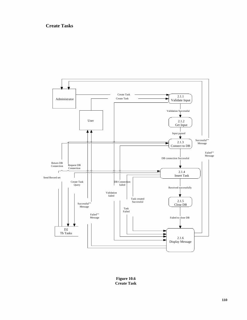
110
Create Tasks
Administrator 2.1.1
Validate Input
Validation Successful
Create Task Create Task
User
Input passed
2.1.3 Connect to DB
Successful”” Message
2.1.2 Get Input
Failed”” Message
DB connection Successful
Return DB Connection Request DB
Connection
Received successfully
Send Record set Create Task
Query DB Connection
failed
Task created Successful
2.1.4 Insert Task
Validation failed
D2 Tb Tasks
Failed to close DB
2.1.5 Close DB Successful””
Message Task
Failed Failed”” Message
2.1.6 Display Message
Figure 10.6 Create Task
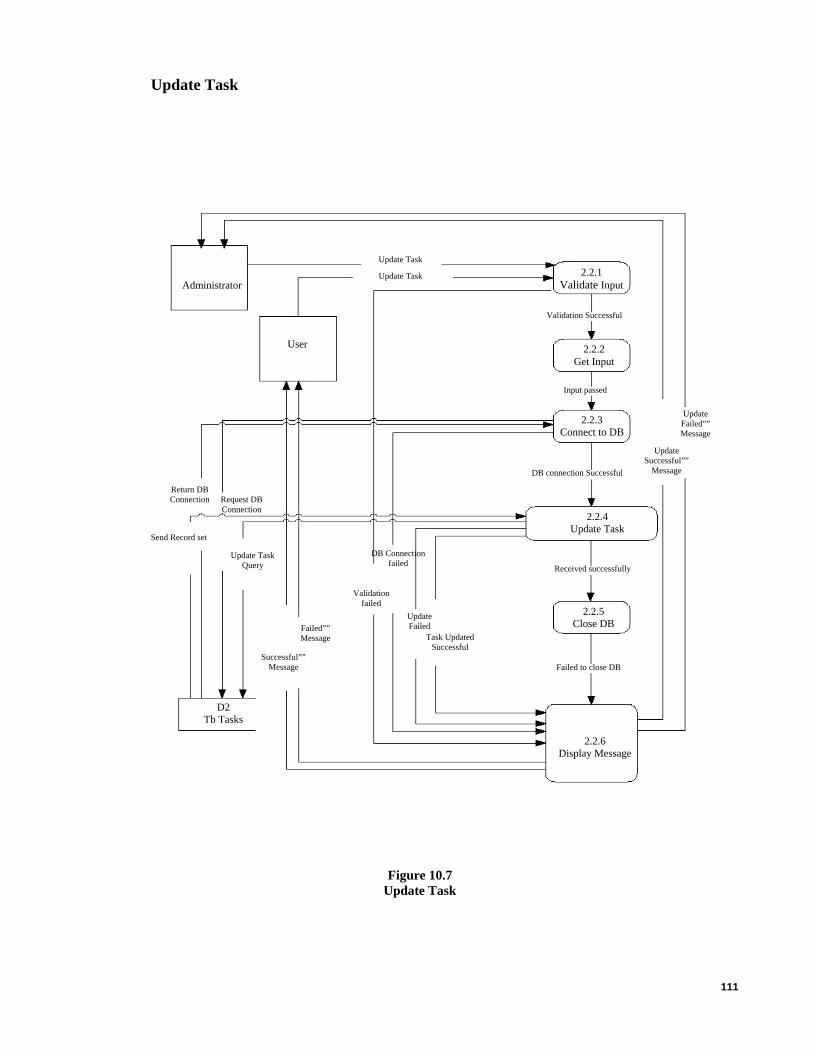
111
Update Task
2.2.2 Get Input
Update Task
Update Task 2.2.1 Validate Input Administrator
Validation Successful
User
Input passed
Update Failed”” Message
2.2.3 Connect to DB
Update Successful””
Message DB connection Successful
Send Record set
Update Task Query
DB Connection failed
2.2.4 Update Task
Received successfully
2.2.5 Close DB Failed””
Message
Return DB Connection Request DB
Connection
Validation failed
Task Updated Successful
Update Failed
Successful”” Message Failed to close DB
D2 Tb Tasks
2.2.6 Display Message
Figure 10.7 Update Task

112
Delete Task
Administrator Delete Task
Validation Successful
User 2.3.2 Get Input
Input passed
Delete Failed””Message
2.3.3 Connect To DB
DB connection Successful
2.3.4 Delete Task
Delete Task Query
DB Connectionfailed
Validation failed
Delete Successful”” Message
Delete Successful
Delete Failed””Message
Delete failed
Failed to close DB
D2 Tb Tasks
2.3.1 Validate Input
Confirm Dialog–Message Yes/No
Delete Task
Delete Successful”” Message
2.3.5 Close DB
Confirm Dialog– Message Yes/No
Send Record Set
Request DB Connection
Return DB Connection
Received successfully
2.3.6 Display Message
Figure 10.8 Delete Task

113
View Task details
Task Information Result
No Task info Result
2.4.5 Close DB
Select TaskSystem Administrator
D2 Tb Tasks
Pass Inputs
Validation Failed
2.4.3 Connect To DB
Task Information Result
2.4.4 Retrieve Task Information
User
Validation Successful
DB Connection Successful
DB Connection Failed Error Message
No Task info Result
2.4.6 Display Message
View Successful
Received Record set
Return DB Connection
2.4.2 Get Input
View Failed Record set
Error Message
Request DB Connection
View SQL Query
2.4.1 Validate
Input
Select Task
Close DB Connation Failed
Figure 10.9 View Task Details

114
Search Task
Administrator 2.5.1
Validate Input
User
Search Task
Search Task
Validation Successful
2.5.2 Get Input
Input passed
2.5.3 Connect To DB
DB connection Successful
2.5.4 Search Task
Send Record set
Search Task Query
Request DB Connection
DB Connectionfailed
Search Task failed
Validation failed
Return DB Connection
Received successfully
2.5.5 Close DB
2.5.6 Display Message
D2 Tb Tasks
Failed to close DB
Figure 10.10 Search Task

115
Create Features
3.1.1 Validate Input
3.1.2 Get Input
Administrator
Validation Successful
Create Feature Create Feature
User
Input passed
3.1.3 Connect to DB
Successful”” Message
3.1.5 Close DB
3.1.4 Insert Feature
Failed”” Message
DB connection Successful
3.1.6 Display Message
Return DB Connection Request DB
Connection
Received successfully
Send Record set Create Feature
Query DB Connection
failed
Feature created Successful
Validation failed
D2 Tb Features
Failed to close DB
Successful”” Message
Feature Failed
Failed”” Message
Figure 10.11 Create Feature

116
Update Feature
Update Feature
Update Feature 3.2.1 Validate Input
3.2.2 Get Input
Administrator
Validation Successful
User
Input passed
Update Failed”” Message
3.2.3 Connect to DB
Update Successful””
Message DB connection Successful
Send Record set
Update Feature Query
DB Connection failed
3.2.4 Update Feature
Received successfully
3.2.5 Close DB Failed””
Message
Return DB Connection Request DB
Connection
Validation failed
Feature Updated
Successful
Update Failed
Successful”” Message Failed to close DB
D2 Tb Features
3.2.6 Display Message
Figure 10.12 Update Feature

117
Delete a Feature
Administrator Delete Feature 3.3.1
Validate Input
Validation Successful
User 3.3.2 Get Input
Delete Failed””Message
3.3.3 Connect To DB
DB connection Successful
3.3.4 Delete Feature
Delete Feature Query
DB Connectionfailed
Validation failed
Received successfully
Delete Successful”” Message
Delete Successful
Delete Failed””Message
Delete failed
Failed to close DB
D2 Tb Features
Input passed
Confirm Dialog–Message Yes/No
Delete Feature
Delete Successful”” Message
3.3.5 Close DB
3.3.6 Display Message
Confirm Dialog– Message Yes/No
Send Record Set
Request DB Connection
Return DB Connection
Figure 10.13 Delete Feature
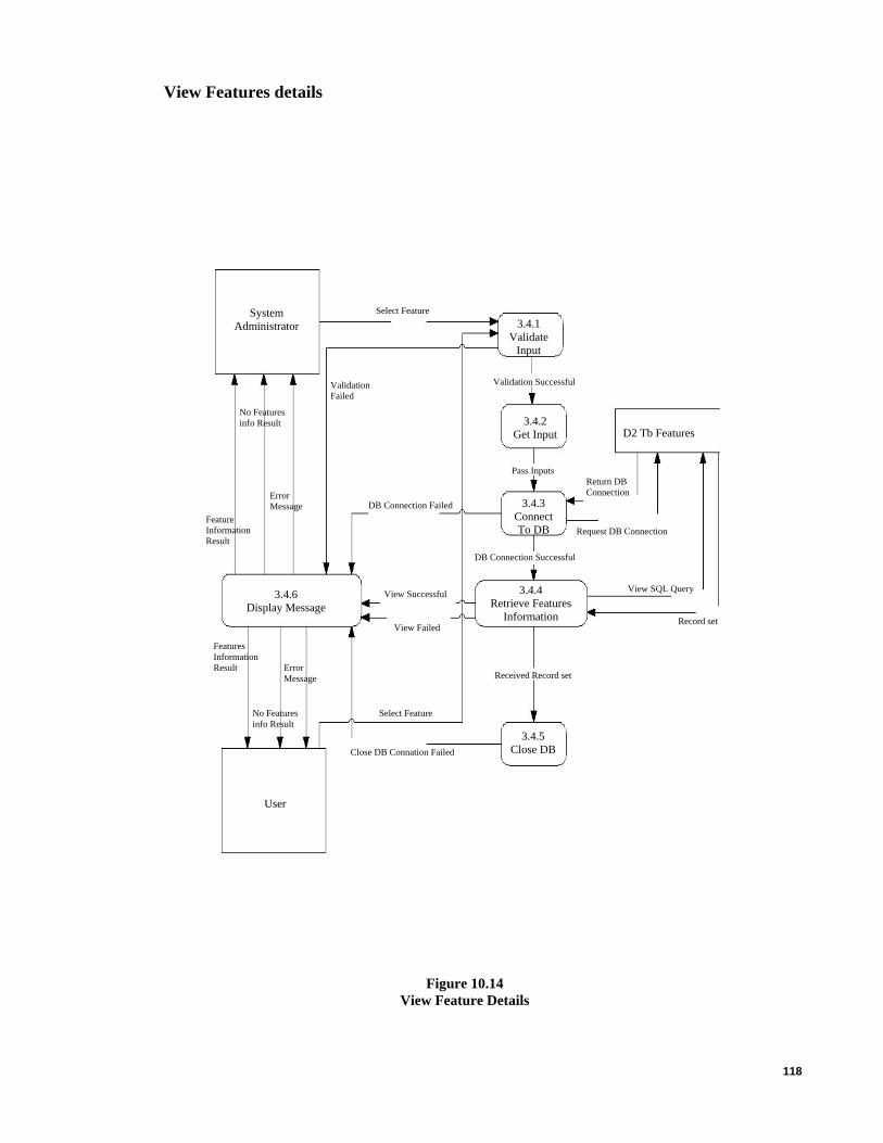
118
View Features details
Features Information Result
No Features info Result
3.4.3 Connect To DB
Select FeatureSystem Administrator
3.4.5 Close DB
D2 Tb Features
Pass Inputs
Validation Failed
User
Feature Information Result
3.4.4 Retrieve Features
Information
Validation Successful
DB Connection Successful
DB Connection Failed Error Message
No Features info Result
3.4.6 Display Message
View Successful
Received Record set
Return DB Connection
3.4.2 Get Input
View Failed Record set
Error Message
Request DB Connection
View SQL Query
3.4.1 Validate
Input
Select Feature
Close DB Connation Failed
Figure 10.14 View Feature Details

119
Search Features
4.4.5 Close DB
Administrator 3.5.1
Validate Input
User
Search Features
Search Features
Validation Successful
3.5.2 Get Input
Input passed
D2 Tb Feature
3.5.3 Connect To DB
DB connection Successful
3.5.4 Search Feature
Send Record set
Search Feature Query
Request DB Connection
DB Connectionfailed
Search Featurefailed
Validation failed
Return DB Connection
Received successfully
3.5.5 Close DB
3.5.6 Display Message
Figure 10.15 Search Feature

120
Create Milestone
Administrator 4.1.1
Validate Input
Validation Successful
Create Milestone Create Milestone
4.1.2 Get Input
User
Input passed
4.1.3 Connect to DB
Successful”” Message
4.1.4 Insert Milestone
Failed”” Message
DB connection Successful
4.1.5 Close DB
Return DB Connection Request DB
Connection
Received successfully
Send Record set Create
Milestone Query
DB Connection failed
Milestone created
Successful
4.1.6 Display Message
Validation failed
D2 Tb Milestone
Failed to close DB
Successful”” Message
Milestone Failed
Figure 10.16 Create Milestones
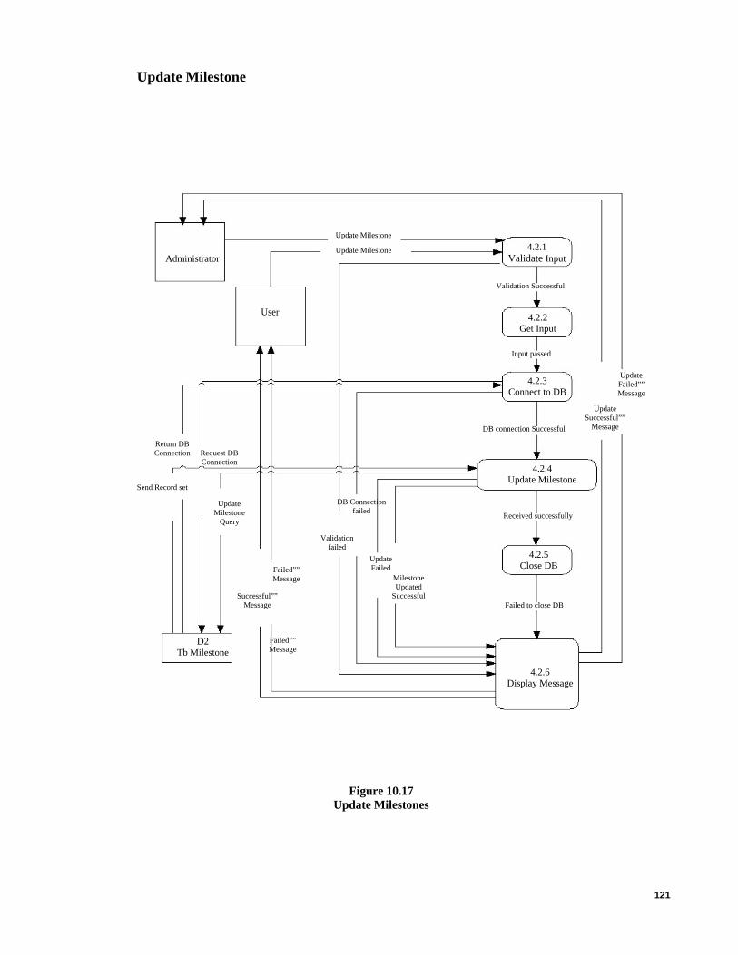
121
Update Milestone
Failed”” Message
Update Milestone
Update Milestone 4.2.1 Validate Input Administrator
Validation Successful
4.2.2 Get Input
User
Input passed
Update Failed”” Message
4.2.3 Connect to DB
Update Successful””
Message DB connection Successful
Send Record set
Update Milestone
Query
DB Connection failed
4.2.4 Update Milestone
Received successfully
4.2.5 Close DB Failed””
Message
Return DB Connection Request DB
Connection
Validation failed
Milestone Updated
Successful
Update Failed
Successful”” Message Failed to close DB
D2 Tb Milestone
4.2.6 Display Message
Figure 10.17 Update Milestones

122
Delete Milestone
Administrator Delete Milestone
Validation Successful
User 4.3.2 Get Input
Input passed
Delete Failed””Message
4.3.3 Connect To DB
DB connection Successful
4.3.4 Delete Milestone
Delete Milestone Query
DB Connectionfailed
Validation failed
Received successfully
Delete Successful”” Message
Delete Successful
Delete Failed””Message
Delete failed
Failed to close DB
D2 Tb Milestone
4.3.1 Validate Input
Confirm Dialog–Message Yes/No
Delete Milestone
Delete Successful”” Message
4.3.5 Close DB
Confirm Dialog– Message Yes/No
Send Record Set
Request DB Connection
Return DB Connection
4.3.6 Display Message
Figure 10.18 Delete Milestone

123
View Milestone details
Milestone Information Result
No Milestone info Result
Select MilestoneSystem Administrator
D2 Tb Milestone
Pass Inputs
Validation Failed
4.4.3 Connect To DB
Milestone Information Result
4.4.4 Retrieve Milestone
Information
User
Validation Successful
DB Connection Successful
DB Connection Failed Error Message
No Milestone info Result
4.4.6 Display Message
View Successful
Received Record set
Return DB Connection
4.4.2 Get Input
View Failed Record set
Error Message
Request DB Connection
View SQL Query
4.4.1 Validate
Input
Select Milestone
Close DB Connation Failed 4.4.5
Close DB
Figure 10.19 View Milestone Details

124
Search Milestone
Administrator 4.5.1
Validate Input
User
Search Milestone
Search Milestone
Validation Successful
4.5.2 Get Input
Input passed
4.5.3 Connect To DB
DB connection Successful
4.5.4 Search Milestone
Send Record set
Search Milestone Query
Request DB Connection
DB Connectionfailed
Search Milestone failed
Validation failed
Return DB Connection
Received successfully
4.5.5 Close DB
4.5.6 Display Message
D2 Tb Milestone
Failed to close DB
Figure 10.20 Search Milestone

125
Create Releases
Administrator 5.1.1
Validate Input
Validation Successful
Create Release Create Release
5.1.2 Get Input
User
Input passed
5.1.3 Connect to DB
Successful”” Message
5.1.4 Insert Release
Failed”” Message
DB connection Successful
Return DB Connection Request DB
Connection
5.1.5 Close DB
Received successfully
5.1.6 Display Message
Send Record set Create Release
Query DB Connection
failed
Release Created Successful
Validation failed
D2 Tb Releases
Failed to close DB
Successful”” Message
Release Failed
Figure 10.21 Create Releases

126
Update Releases
Failed”” Message
Update Release
Update Release 5.2.1 Validate Input Administrator
Validation Successful
5.2.2 Get Input
User
Input passed
Update Failed”” Message
5.2.4 Update Release
5.2.6 Display Message
5.2.3 Connect to DB
Update Successful””
Message DB connection Successful
Send Record set
Update Release Query
DB Connection failed Received successfully
5.2.5 Close DB Failed””
Message
Return DB Connection Request DB
Connection
Validation failed
Release Updated
Successful
Update Failed
Successful”” Message Failed to close DB
D2 Tb Releases
Figure 10.22 Update Releases

127
Delete Releases
5.3.1 Validate Input
Administrator Delete Release
Validation Successful
User 5.3.2 Get Input
Input passed
Delete Failed””Message
5.3.3 Connect To DB
DB connection Successful
5.3.4 Delete Release
Delete Release Query
DB Connectionfailed
Validation failed
Received successfully
Delete Successful”” Message
Delete Successful
Delete Failed”” Message
Delete failed
Failed to close DB
D2 Tb Releases
Confirm Dialog–Message Yes/No
5.3.5 Close DB
Delete Release
Delete Successful”” Message
5.3.6 Display Message
Confirm Dialog– Message Yes/No
Send Record Set
Request DB Connection
Return DB Connection
Figure 10.23 Delete Releases
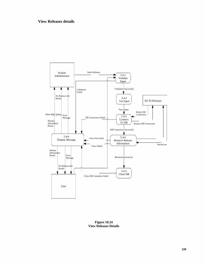
128
View Releases details
5.4.1 Validate
Input
Release Information Result
No Release info Result
5.4.5 Close DB
5.4.6 Display Message
Close DB Connation Failed
Select ReleaseSystem Administrator
D2 Tb Releases
Pass Inputs
Validation Failed
Release Information Result
5.4.4 Retrieve Release
Information
User
Validation Successful
DB Connection Successful
DB Connection Failed Error Message
No Release info Result
View Successful
Received Record set
Return DB Connection
5.4.2 Get Input
View Failed Record set
Error Message
5.4.3 Connect To DB Request DB Connection
Figure 10.24 View Releases Details
View SQL Query
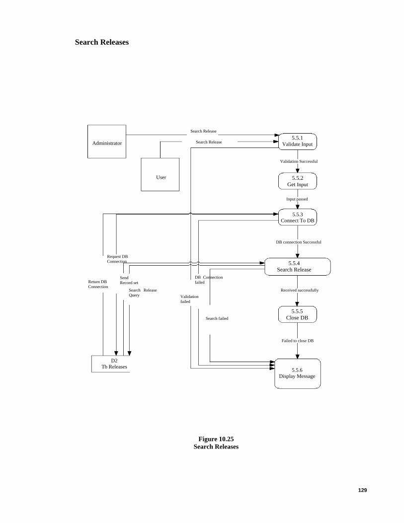
129
Search Releases
5.5.4 Search Release
Administrator 5.5.1
Validate Input
Received successfully
User
Search Release
Search Release
Validation Successful
5.5.2 Get Input
Input passed
D2 Tb Releases 5.5.6
Display Message
Failed to close DB
5.5.3 Connect To DB
DB connection Successful
Send Record set
Search Release Query
Request DB Connection
DB Connectionfailed
Search failed
Validation failed
Return DB Connection
5.5.5 Close DB
Figure 10.25 Search Releases

130
Create Links
6.1.1 Validate Input Administrator
Validation Successful
Create Link Create Link
Successful”” Message
Link Failed
6.1.2 Get Input
Failed”” Message
User
Input passed
6.1.5 Close DB
D2 Tb Links
6.1.3 Connect to DB
Successful”” Message
6.1.4 Insert Link
Failed”” Message
DB connection Successful
6.1.6 Display Message
Return DB Connection Request DB
Connection
Received successfully
Send Record set Create Link
Query DB Connection
failed Validation Failed
Created Successful
Figure 10.26 Create Links
Failed to close DB

131
Update Links
Successful”” Message
Failed to close DB
D2 Tb Links
Update Link
Update Link 6.2.1 Validate Input
6.2.6 Display Message
Administrator
Validation Successful
6.2.2 Get Input
User
Input passed
Update Failed”” Message
6.2.3 Connect to DB
Update Successful””
Message DB connection Successful
Send Record set
Update Link Query
DB Connection failed
6.2.4 Update Link
Received successfully
6.2.5 Close DB Failed””
Message
Return DB Connection Request DB
Connection
Validation failed
Updated Successful
Update Failed
Figure 10.27 Update Links

132
Delete Links
Administrator Delete Link
Validation Successful
User 6.3.2 Get Input
Input passed
Delete Failed””Message
6.3.3 Connect To DB
DB connection Successful
6.3.4 Delete Link
Delete Link Query
DB Connectionfailed
Validation failed
Received successfully
Delete Successful”” Message
Delete Successful
Delete Failed””Message
Delete failed
Failed to close DB
D2 Tb Links 6.3.6
Display Message
6.3.1 Validate Input
Confirm Dialog–Message Yes/No
Delete Link
Delete Successful”” Message
6.3.5 Close DB
Confirm Dialog– Message Yes/No
Send Record Set
Request DB Connection
Return DB Connection
Figure 10.28 Delete Links

133
View Links details
System Administrator
Select Link
Link Information Result
No Link info Result
D2 Tb Links
Pass Inputs
Validation Failed
Link Information Result
6.4.4 Retrieve Link Information
User
Validation Successful
DB Connection Successful
DB Connection Failed Error Message
No Link info Result
6.4.6 Display Message
View Successful
Received Record set
Return DB Connection
6.4.2 Get Input
View Failed
Error Message
Request DB Connection
View SQL Query
6.4.1 Validate
Input
Select Link
Close DB Connation Failed 6.4.5
Close DB
6.4.3 Connect To DB
Record set
Figure 10.29 View Link Details

134
Search Links
D2 Tb Links
Administrator 6.5.1
Validate Input
User
Search Link
Search Link
Validation Successful
6.5.2 Get Input
Input passed
6.5.3 Connect To DB
DB connection Successful
6.5.4 Search Link
Send Record set
Search Link Query
Request DB Connection
DB Connectionfailed
Search failed
Validation failed
Return DB Connection
Received successfully
6.5.5 Close DB
6.5.6 Display Message
Figure 10.30 Search Links

135
Create Organization
Failed”” Message
Failed
Validation failed
Administrator 7.1.1
Validate Input
Validation Successful
Create Organization Create Organization
7.1.2 Get Input
Successful”” Message
User
Input passed
7.1.3 Connect to DB
Successful”” Message
7.1.4 Insert Organization
Failed”” Message
DB connection Successful
7.1.5 Close DB
D2 Tb Organization
Return DB Connection Request DB
Connection
Received successfully
Send Record set Create
Organization Query
DB Connection failed
Created Successful
7.1.6 Display Message
Figure 10.31 Create Organizations

136
Update Organization
Successful”” Message
7.2.2 Get Input
Update Organization
Update Organization 7.2.1 Validate Input Administrator
Validation Successful
User
Input passed
Update Failed”” Message
7.2.3 Connect to DB
Update Successful””
Message DB connection Successful
Send Record set
Update Query DB Connection failed
7.2.4 Update Organization
Received successfully
7.2.5 Close DB Failed””
Message
Return DB Connection Request DB
Connection
Validation failed
Updated Successful
Update Failed
Failed to close DB
D2 Tb Organization
7.2.6 Display Message
Figure 10.32 Update Organization
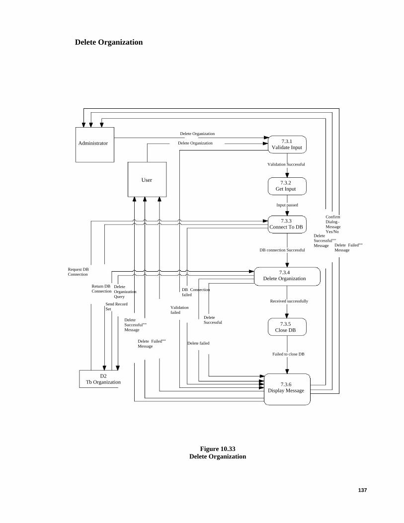
137
Delete Organization
Administrator Delete Organization
Validation Successful
User 7.3.2 Get Input
Delete Failed””Message
7.3.3 Connect To DB
DB connection Successful
7.3.4 Delete Organization
Delete Organization Query
DB Connectionfailed
Validation failed
Received successfully
Delete Successful”” Message
Delete Successful
Delete Failed””Message
Delete failed
7.3.5 Close DB
Failed to close DB
D2 Tb Organization 7.3.6
Display Message
7.3.1 Validate Input
Request DB Connection
Return DB Connection
Send Record Set
Input passed
Confirm Dialog–Message Yes/No
Delete Organization
Delete Successful”” Message
Figure 10.33 Delete Organization
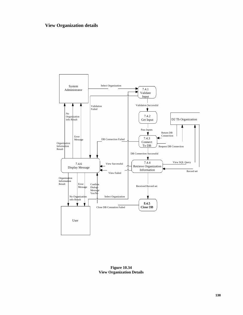
138
View Organization details
Confirm Dialog– Message Yes/No
8.4.5 Close DB
Organization Information Result
No Organization info Result
Select OrganizationSystem Administrator
7.4.3 Connect To DB
D2 Tb Organization
Pass Inputs
Validation Failed
Organization Information Result
7.4.4 Retrieve Organization
Information
User
Validation Successful
DB Connection Successful
DB Connection Failed Error Message
No Organization info Result
7.4.6 Display Message
View Successful
Received Record set
Return DB Connection
7.4.2 Get Input
View Failed Record set
Error Message
Request DB Connection
View SQL Query
7.4.1 Validate
Input
Select Organization
Close DB Connation Failed 7.4.5
Close DB
Figure 10.34 View Organization Details

139
Search Organization
Search Organization
Administrator 7.5.1
Validate Input
User
Search Organization
Validation Successful
7.5.2 Get Input
Input passed
7.5.3 Connect To DB
DB connection Successful
7.5.4 Search Organization
Send Record set
Search Organization Query
Request DB Connection
DB Connectionfailed
Search Failed
Validation failed
Return DB Connection
Received successfully
7.5.5 Close DB
7.5.6 Display Message
D2 Tb Organization
Figure 10.35 Search Organization
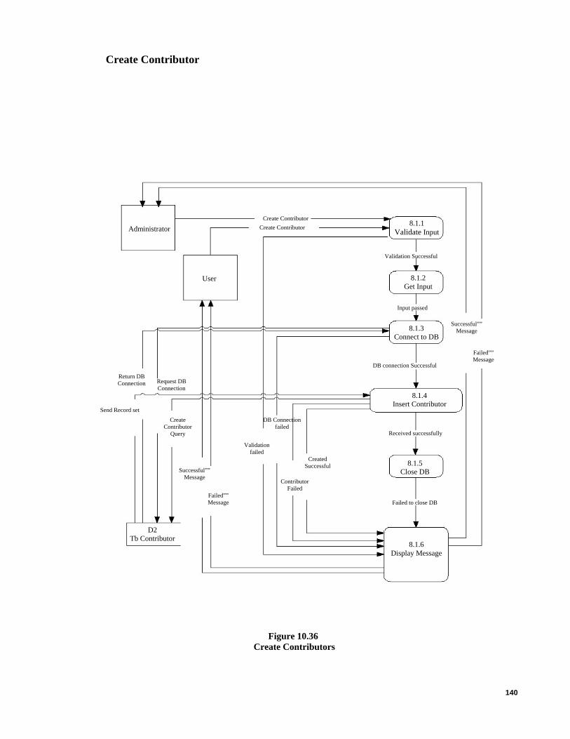
140
Create Contributor
8.1.1 Validate Input Administrator
Validation Successful
Create Contributor Create Contributor
8.1.2 Get Input
User
Input passed
8.1.3 Connect to DB
Successful”” Message
8.1.4 Insert Contributor
Failed”” Message
DB connection Successful
8.1.5 Close DB
Return DB Connection Request DB
Connection
Received successfully
Send Record set Create
Contributor Query
DB Connection failed
Created Successful
Contributor Failed
8.1.6 Display Message
Validation failed
D2 Tb Contributor
Failed to close DB
Successful”” Message
Failed”” Message
Figure 10.36 Create Contributors
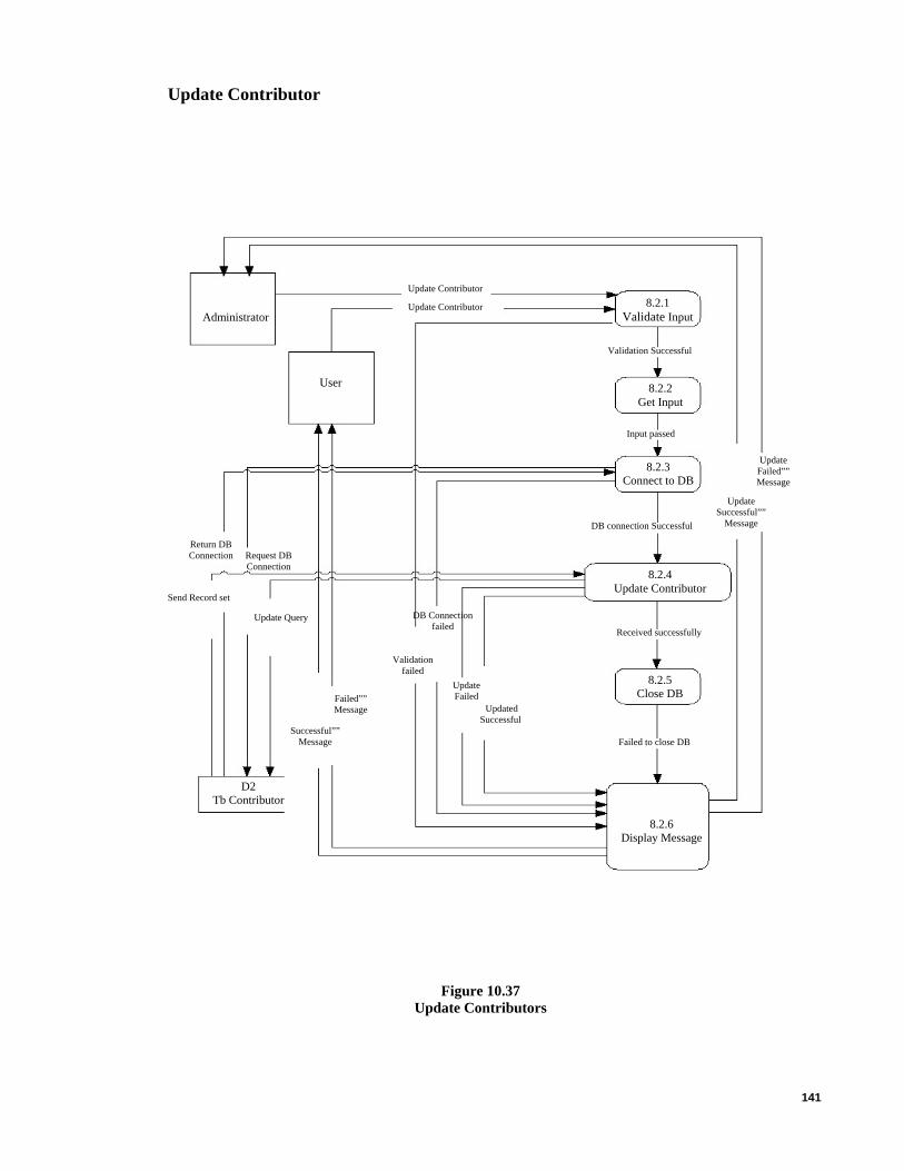
141
Update Contributor
8.2.2 Get Input
Update Contributor
Update Contributor 8.2.1 Validate Input Administrator
Validation Successful
8.2.4 Update Contributor
User
Input passed
Update Failed”” Message
8.2.3 Connect to DB
Update Successful””
Message DB connection Successful
Send Record set
Update Query DB Connection failed Received successfully
8.2.5 Close DB Failed””
Message
Return DB Connection Request DB
Connection
Validation failed
Updated Successful
Update Failed
Successful”” Message Failed to close DB
D2 Tb Contributor
8.2.6 Display Message
Figure 10.37 Update Contributors

142
Delete Contributor
Administrator Delete Contributor 8.3.1 Validate Input
Validation Successful
User 8.3.2 Get Input
Input passed
Delete Failed””Message
8.3.3 Connect To DB
DB connection Successful
8.3.4 Delete Contributor
Delete Contributor Query
DB Connectionfailed
Validation failed
Received successfully
Delete Successful”” Message
Delete Successful
Delete Failed””Message
Delete failed
8.3.5 Close DB
Failed to close DB
Confirm Dialog–Message Yes/No
Delete Contributor
Delete Successful”” Message
8.3.6 Display Message
Confirm Dialog– Message Yes/No
Send Record Set
Request DB Connection
Return DB Connection
D2 Tb Contributor
Figure 10.38 Delete Contributor
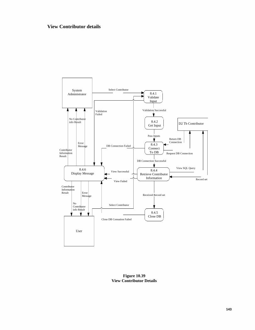
143
View Contributor details
8.4.1 Validate
Input
Contributor Information Result
No Contributor info Result
8.4.5 Close DB
Close DB Connation Failed
View SQL Query
D2 Tb Contributor
Select Contributor
Select ContributorSystem Administrator
8.4.3 Connect To DB
Pass Inputs
Validation Failed
8.4.6 Display Message
Contributor Information Result
8.4.4 Retrieve Contributor
Information
User
Validation Successful
DB Connection Successful
DB Connection Failed Error Message
No Contributor info Result
View Successful
Received Record set
Return DB Connection
8.4.2 Get Input
View Failed Record set
Error Message
Request DB Connection
Figure 10.39 View Contributor Details
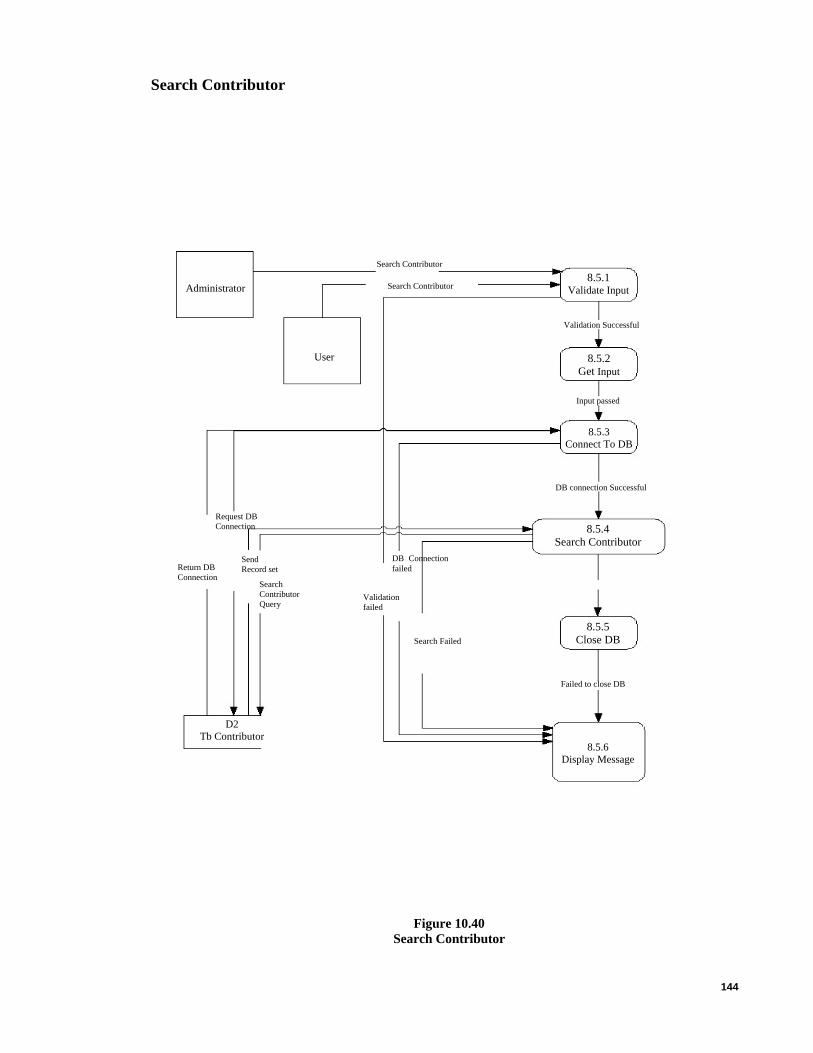
144
Search Contributor
8.5.5 Close DB
8.5.4 Search Contributor
Administrator 8.5.1
Validate Input
User
Search Contributor
Search Contributor
Validation Successful
8.5.2 Get Input
Input passed
D2 Tb Contributor
8.5.6 Display Message
Failed to close DB
8.5.3 Connect To DB
DB connection Successful
Send Record set
Search Contributor Query
Request DB Connection
DB Connectionfailed
Search Failed
Validation failed
Return DB Connection
Figure 10.40 Search Contributor

145
Create Category
9.1.1 Validate Input Administrator
Validation Successful
Create Category Create Category
9.1.2 Get Input
User
Input passed
9.1.3 Connect to DB
Successful”” Message
9.1.4 Insert Category
Failed”” Message
DB connection Successful
9.1.5 Close DB
Return DB Connection Request DB
Connection
Received successfully
Successful”” Message
Send Record set Create
Category Query DB Connection
failed
Category created
Successful Category
Failed
Failed”” Message
Validation failed
D2 Tb Category
Failed to close DB
9.1.6 Display Message
Figure 10.41 Create Categories
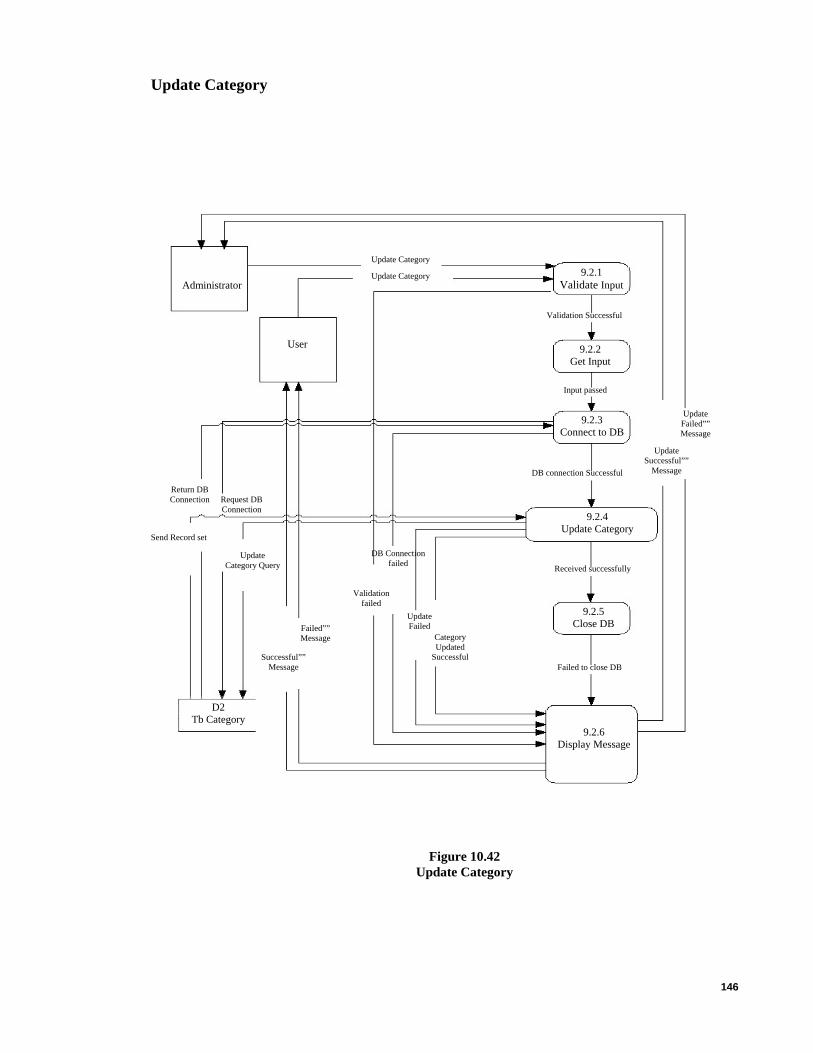
146
Update Category
Update Category
Update Category 9.2.1 Validate Input
9.2.2 Get Input
Administrator
Validation Successful
Failed to close DB
User
Input passed
Update Failed”” Message
9.2.3 Connect to DB
Update Successful””
Message DB connection Successful
9.2.6 Display Message
Send Record set
Update Category Query
DB Connection failed
9.2.4 Update Category
Received successfully
9.2.5 Close DB Failed””
Message
Return DB Connection Request DB
Connection
Validation failed
Category Updated
Successful
Update Failed
Successful”” Message
Figure 10.42 Update Category
D2 Tb Category

147
Delete Category
Administrator Delete Category
Validation Successful
User 9.3.2 Get Input
Delete Failed””Message
9.3.3 Connect To DB
DB connection Successful
9.3.4 Delete Category
Delete Category Query
DB Connectionfailed
Validation failed
Received successfully
Delete Successful”” Message
Delete Successful
Delete Failed”” Message
Delete failed
Failed to close DB
D2 Tb Category
9.3.1 Validate Input
Input passed
Confirm Dialog–Message Yes/No
Delete Category
Delete Successful”” Message
9.3.6 Display Message
9.3.5 Close DB
Confirm Dialog– Message Yes/No
Send Record Set
Request DB Connection
Return DB Connection
Figure 10.43 Delete Category

148
View Category details
View SQL Query
Close DB Connation Failed
Select Category
View Failed
Request DB Connection
9.4.1 Validate
Input
Category Information Result
No Category info Result
9.4.3 Connect To DB
Select CategorySystem Administrator
D2 Tb Category
Pass Inputs
Validation Failed
Record set
Category Information Result
9.4.4 Retrieve Category
Information
User
Validation Successful
DB Connection Successful
DB Connection Failed Error Message
No Category info Result
9.4.6 Display Message
View Successful
Received Record set
Return DB Connection
9.4.2 Get Input
9.4.5 Close DB
Figure 10.44 View Category Details
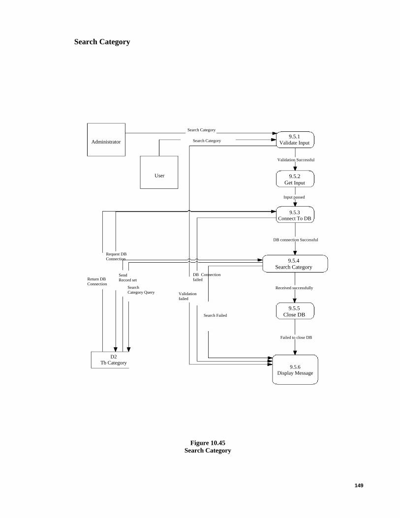
149
Search Category
Administrator 9.5.1
Validate Input
User
Search Category
Search Category
Validation Successful
9.5.2 Get Input
Input passed
9.5.3 Connect To DB
DB connection Successful
9.5.4 Search Category
Send Record set
Search Category Query
Request DB Connection
DB Connectionfailed
Search Failed
Validation failed
Return DB Connection
Received successfully
9.5.5 Close DB
9.5.6 Display Message
D2 Tb Category
Failed to close DB
Figure 10.45 Search Category

150
APPENDIX E –APPLICATION TEST RESULT AND GUI
Login Screen
Below is the login screen for the user to key in their user name and password.
Figure 11.1 Login Screen
Testing of valid user
User need to key in the correct user name and password to log into the system as Screen
below Figure 11.2 display’s the error message as user enters wrong password or user name.

151
Figure 11.2 Invalid User
After Valid User
Once the correct user name and password is keyed in, the application will straight go to
application Dashboard where user can see all the projects with their details and their related
tasks that need to be done during project management shown in Figure 11.3.
Main Screen of the Application Software Projects
User will see all the projects and their details in a single view report format on the
dashboard of the application, which will be easy to maintain as all the related work can be
done on the same screen i.e. View project definition, create project, delete project, Manage
organization, create tasks, create milestones and other related work as for a project as
shown in the Figure 11.3 below.

152
In the main screen user will see 7 tabs, which include view of the each project details i.e.
Project, tasks, features, milestones, releases and links for a particular project.
Figure 11.3 Project Management Dashboard
Create a Project
User will be able to create or update a project and its details once successfully login. User
needs to press “Create Project” button to create a new project and its details as shown in the
figure 11.3. Once a Project has been created the information need to be key in as shown
below in the figure 11.4 and figure11.5.
Once all the information is key in the user need to Press the “Create “ button to save the
project details, user can also press the “Cancel” button to cancel the record to be saved as
shown below in figure 11.4.

153
Figure 11.4 Create Project
Figure 11.5 Create Project cont

154
Once the project is created user can view the details by pressing “Project” tab as shown
below in the figure 11.6. User can update the information for a particular project by
pressing the “Edit Project” button or to create a new project press “Create Project” button
as shown below in the figure 11.6.
Figure 11.6 View Project
Update Project Details
Once the “Edit Project” button is pressed user will be able to change the information of the
project, once the information has been change then user need to press “Apply Changes”
button as shown below in figure 11.7. User will be also able to delete a project by pressing
the “Delete” button or to cancel the changes then user just need to press the “Cancel”
button as shown below in the figure11.7.
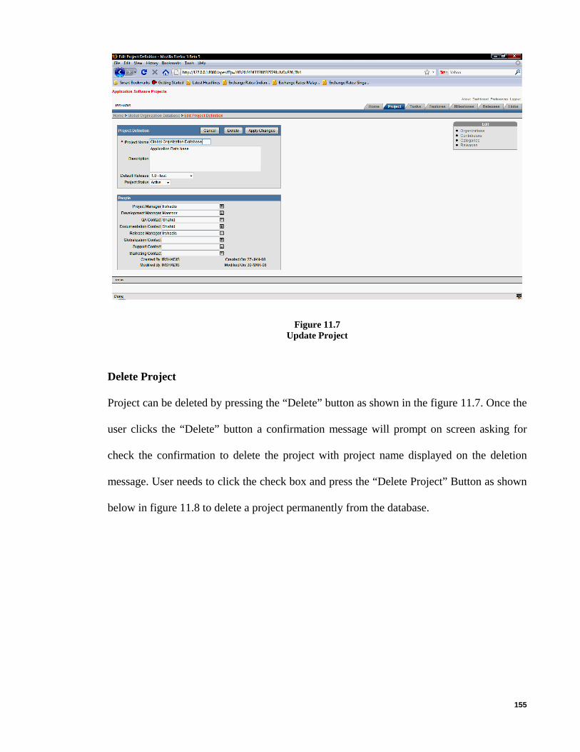
155
Figure 11.7 Update Project
Delete Project
Project can be deleted by pressing the “Delete” button as shown in the figure 11.7. Once the
user clicks the “Delete” button a confirmation message will prompt on screen asking for
check the confirmation to delete the project with project name displayed on the deletion
message. User needs to click the check box and press the “Delete Project” Button as shown
below in figure 11.8 to delete a project permanently from the database.

156
Figure 11.8 Delete Project
Create Task
Tasks need to be created for each project. To create a task user need to press the “Task” tab,
as the “Task” tab will show all the tasks for a particular project as show below in the figure
11.9. User can create or view the tasks details in this tab. To create a task user need to press
the “Create task” button to create a task as shown below in figure 11.9. Task can be also
edited by clicking the “Paper and pencil” image shown below in the figure 11.9 left side of
the screen.
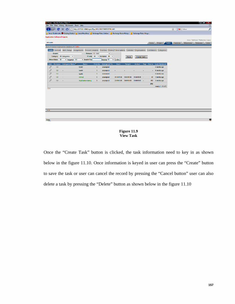
157
Figure 11.9 View Task
Once the “Create Task” button is clicked, the task information need to key in as shown
below in the figure 11.10. Once information is keyed in user can press the “Create” button
to save the task or user can cancel the record by pressing the “Cancel button” user can also
delete a task by pressing the “Delete” button as shown below in the figure 11.10
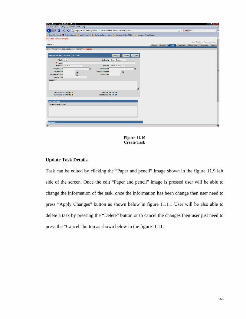
158
Figure 11.10 Create Task
Update Task Details
Task can be edited by clicking the “Paper and pencil” image shown in the figure 11.9 left
side of the screen. Once the edit “Paper and pencil” image is pressed user will be able to
change the information of the task, once the information has been change then user need to
press “Apply Changes” button as shown below in figure 11.11. User will be also able to
delete a task by pressing the “Delete” button or to cancel the changes then user just need to
press the “Cancel” button as shown below in the figure11.11.

159
Figure 11.11 Update Task
Delete Task
Task can be deleted by pressing the “Delete” button as shown in the figure 11.12. Once the
user clicks the “Delete” button a confirmation message will prompt on screen asking for the
confirmation to delete the task press “ok” to delete and ‘Cancel’ to stop deletion as shown
below in figure 11.12.

160
Figure 11.12 Delete Task
Download Task Details
Task details can be downloaded in CSV file by pressing on the text ‘CSV’ at the bottom on
the left side of the application as shown below in the figure 11.13 and the result of CSV file
is shown below in the figure 11.14

161
Figure 11.13 Download Task Details
Figure 11.14 Task Detail CSV
Download Task Details in CSV file
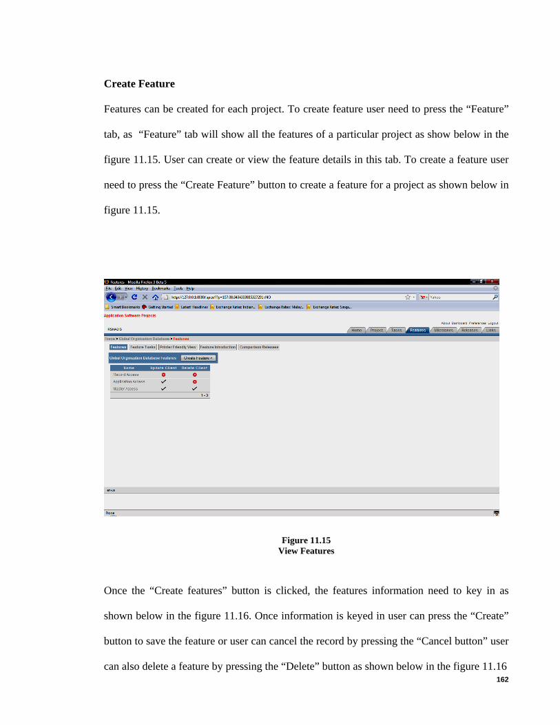
162
Create Feature
Features can be created for each project. To create feature user need to press the “Feature”
tab, as “Feature” tab will show all the features of a particular project as show below in the
figure 11.15. User can create or view the feature details in this tab. To create a feature user
need to press the “Create Feature” button to create a feature for a project as shown below in
figure 11.15.
Figure 11.15 View Features
Once the “Create features” button is clicked, the features information need to key in as
shown below in the figure 11.16. Once information is keyed in user can press the “Create”
button to save the feature or user can cancel the record by pressing the “Cancel button” user
can also delete a feature by pressing the “Delete” button as shown below in the figure 11.16

163
Figure 11.16 Create Feature
Update Feature Details
This screen shows all features for a particular project in the report form at the right side,
which can be, edit at the same time. And down portion is for the previous releases as shown
below in figure 11.17. User will be able to change the information of the features, once the
information has been change then user need to press “Apply Changes” button as shown
below in figure 11.17. User will be also able to delete a feature by pressing the “Delete”
button or to cancel the changes then user just need to press the “Cancel” button as shown
below in the figure11.17.

164
Figure 11.17 Update Feature
Delete Feature
Features can be deleted by pressing the “Delete” button as shown in the figure 11.18. Once
the user clicks the “Delete” button a confirmation message will prompt on screen asking for
the confirmation to delete the feature press “ok” to delete and ‘Cancel’ to stop deletion as
shown below in figure 11.18.

165
Figure 11.18 Delete Feature
Create Milestone
Milestones need to be created for each project. To create a milestone user need to press the
“Milestone” tab, as the “Milestone” tab will show all the milestones for a particular project
as show below in the figure 11.19. User can create or view the milestone details in this tab.
To create a milestone user need to press the “Create Milestone “button to create a milestone
as shown below in figure 11.19. Milestone can be also edited by clicking the “Paper and
pencil” image shown below in the figure 11.19 left side of the screen.

166
Figure 11.19 View Milestone
Once the “Create Milestone” button is clicked, the milestone information need to key in as
shown below in the figure 11.20. Once information is keyed in user can press the “Create”
button to save the milestone information or user can cancel the record by pressing the
“Cancel button” as shown below in the figure 11.20.

167
Figure 11.20 Create Milestones
Update Milestone Details
Milestone can be edited by clicking the “Paper and pencil” image shown in the figure 11.19
left side of the screen. Once the edit “Paper and pencil” image is pressed user will be able
to change the information of the milestone, once the information has been change then user
need to press “Apply Changes” button as shown below in figure 11.21. User will be also
able to delete a milestone by pressing the “Delete” button or to cancel the changes then user
just need to press the “Cancel” button as shown below in the figure11.21.

168
Figure 11.21 Update Milestone
Delete Milestone
Milestone can be deleted by pressing the “Delete” button as shown in the figure 11.22.
Once the user clicks the “Delete” button a confirmation message will prompt on screen
asking for the confirmation to delete the milestone press “ok” to delete and ‘Cancel’ to
stop deletion as shown below in figure 11.22.
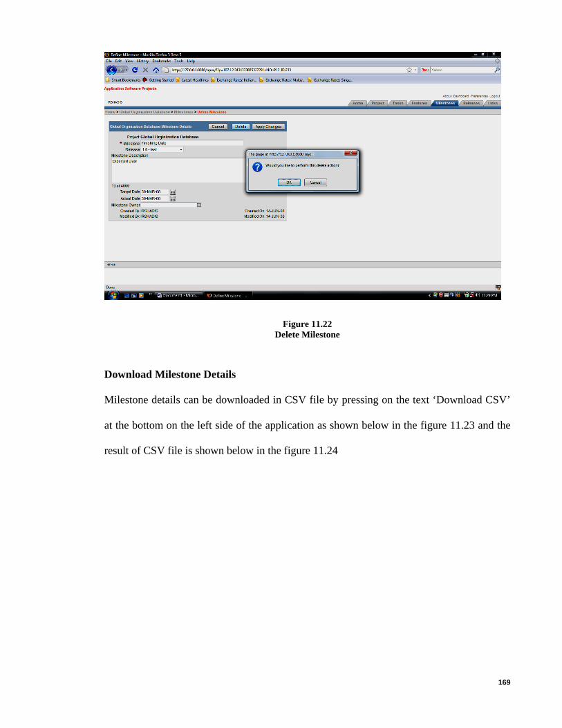
169
Figure 11.22 Delete Milestone
Download Milestone Details
Milestone details can be downloaded in CSV file by pressing on the text ‘Download CSV’
at the bottom on the left side of the application as shown below in the figure 11.23 and the
result of CSV file is shown below in the figure 11.24
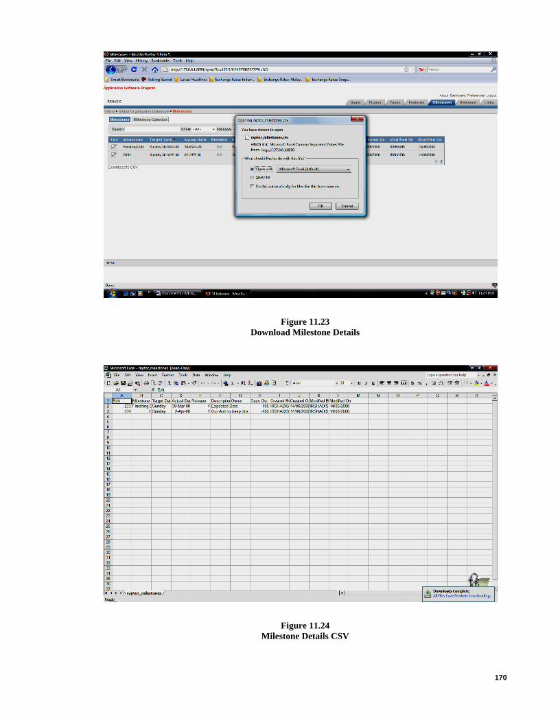
170
Figure 11.23 Download Milestone Details
Figure 11.24 Milestone Details CSV

171
Create Releases
Releases need to be created for each project. To create a release user need to press the
“Releases” tab, as the “Releases” tab will show all the releases for a particular project as
show below in the figure 11.25. User can create or view the Release details in this tab. To
create a release user need to press the “Create Release “button to create a Release as shown
below in figure 11.25. Releases can be also edited by clicking the “Paper and pencil” image
shown below in the figure 11.25 left side of the screen.
Figure 11.25 View Releases

172
Update Releases Details
Releases can be edited by clicking the “Paper and pencil” image shown in the figure 11.25
left side of the screen. Once the edit “Paper and pencil” image is pressed user will be able
to change the information of the Release, once the information has been change then user
need to press “Apply Changes” button as shown below in figure 11.21. User will be also
able to delete a release by pressing the “Delete” button or to cancel the changes then user
just need to press the “Cancel” button as shown below in the figure11.26.
Figure 11.26 Update Releases

173
Delete Release
Release can be deleted by pressing the “Delete” button as shown in the figure 11.27. Once
the user clicks the “Delete” button a confirmation message will prompt on screen asking for
the confirmation to delete the Release press “Ok” to delete and ‘Cancel’ to stop deletion as
shown below in figure 11.27.
Figure 11.27 Delete Releases
Create Link
Link can be created for each project either to link to their web page or to link for testing
purpose. To create a link user need to press the “Link” tab, as the “Link” tab will show all
the Links for a particular project as show below in the figure 11.28. User can create or view
the link details in this tab. To create a link user need to press the “Create Link “button to

174
create a link as shown below in figure 11.28. Link can be also edited by clicking the “Paper
and pencil” image shown below in the figure 11.28 left side of the screen.
Figure 11.28 View Links
Once the “Create link” button is clicked, the link information need to key in as shown
below in the figure 11.29. Once information is keyed in user can press the “Create” button
to save the Link or user can cancel the record not to be save by pressing the “Cancel”
button as shown below in the figure 11.29.
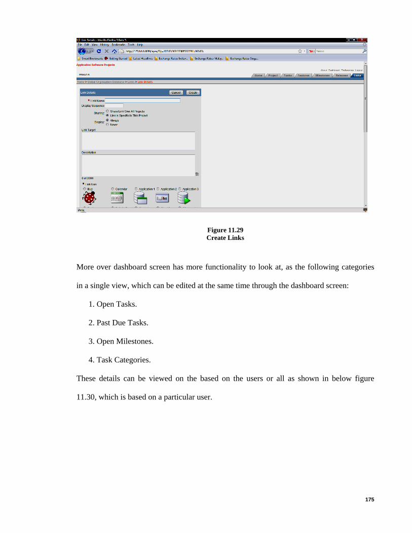
175
Figure 11.29 Create Links
More over dashboard screen has more functionality to look at, as the following categories
in a single view, which can be edited at the same time through the dashboard screen:
1. Open Tasks.
2. Past Due Tasks.
3. Open Milestones.
4. Task Categories.
These details can be viewed on the based on the users or all as shown in below figure
11.30, which is based on a particular user.

176
Figure 11.30 Single View Detail For Projects
Graphical view of open tasks for all the projects is shown below in figure 11.31.
Figure 11.31 Graphical View For All Open Tasks

177
APPENDIX F – USER EVALUATION
Name: ___________________________ Age: _______ Gender: _____
Company: ________________________ Occupation: _______________
1): Login process is secured in which the authentication process functioned properly.
a). Strongly Agree
b). Agree
c). Strongly disagree
d). Disagree
e). Not sure
2): Project information and its related data are captured accurately.
a). Strongly Agree
b). Agree
c). Strongly disagree
d). Disagree
e). Not sure
3): System provides accurate data retrieval from the search mechanism used.
a). Strongly Agree
b). Agree
c). Strongly disagree
d). Disagree
e). Not sure
4): System provides functions that increase the effectiveness in achieving its
development objectives.
a). Strongly Agree
b). Agree
c). Strongly disagree
d). Disagree

178
e). Not sure
5): System response time is faster.
a). Strongly Agree
b). Agree
c). Strongly disagree
d). Disagree
e). Not sure
6): System reporting generation is accurate and properly displayed.
a). Strongly Agree
b). Agree
c). Strongly disagree
d). Disagree
e). Not sure
7): System is functioning according to the expectations during create, delete and
update of any module in the application.
a). Strongly Agree
b). Agree
c). Strongly disagree
d). Disagree
e). Not sure

179
APPENDIX G –USER MANUAL
Deploying Application
Deployment is the process by which one can distribute a finished application or component
to be installed on other computers. To deploy this application on another server, there is
need to install and configure another Oracle Application Express instance. Topics in this
section include:
• Move the Application Definition
• Alternate Authentication Mechanisms to Consider
• Create Users
• Publish the URL
Move the Application Definition
The definition for this application lives within the oracle database. The application
definition includes everything that makes up the application, including the templates, but it
does not include database object definitions or the underlying data. To move an application
to another oracle application express instance, export the application definition from your
development server and import it into your production server.
Topics in this section include:
• Import the application definition into the production instance
• Load the data
Import Application Definition to Production Instance
Log in to the production instance of the workspace home page shown in Figure 12.1 below.

180
Figure 12.1 Apex Workspace Login Home page
On the application home page, click import as shown in Figure 12.2 below.
Figure 12.2 Apex Application Import Homepage

181
On the export/import page, click import and then click next shown in Figure 12.3 below.
Figure 12.3 Apex Application Import/Export Page
For import file as shown in Figure 12.4 and Figure 12.5 below:
1) Import file - Click the browse button and then locate your exported file.
2) File Type - Select application, page, or component export.
3) File character set - accept the default and click next.

182
Figure 12.4 Import Apex Application
Figure 12.5 Application Successfully Imported

183
Once the success message appears, the next step is to install the file. Click install as shown
in Figure 12.6 below.
Figure 12.6 Install Apex Application
Figure 12.7 Application Installed Successfully

184
If the installation is successful, the post-app install utility options page appears as per
Figure 12.7 above. From here, user can select one of the following:
• Select run application to see the application running
• Select application attributes to view the application definition within application
builder
Load the Data
The next step in deploying your application is to load the data. At a minimum, user would
need to populate the main tables in database e.g. SOFTPROJ_PROJECTS,
SOFTPROJ_ORGANIZATIONS etc.
Note there are various mechanisms user could use to accomplish this task, including:
• Use the application itself to create data.
• Use the data Loader to load data copied from a spreadsheet.
• Use SQL scripts and run scripts to create data.
• If user has data existing already within an oracle database, use either
export/import to move data between machines or use SQL to retrieve and
transform existing data and load it into the application tables.
Alternate Authentication Mechanisms to Consider
When the application login page calls the login API with a user name and password, the
application express engine calls the credentials verification method specified in the
application's current authentication scheme. Users have three choices as to how credentials
are verified from within the login API:
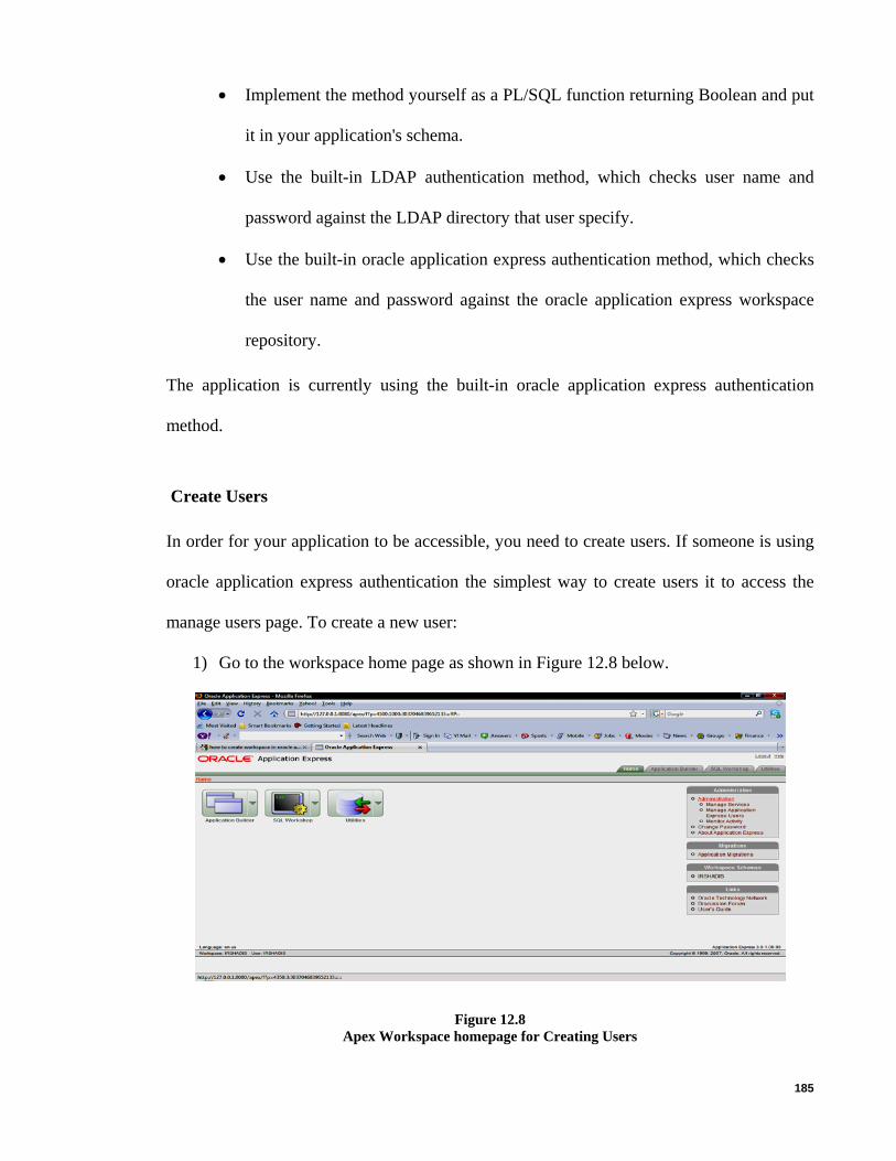
185
• Implement the method yourself as a PL/SQL function returning Boolean and put
it in your application's schema.
• Use the built-in LDAP authentication method, which checks user name and
password against the LDAP directory that user specify.
• Use the built-in oracle application express authentication method, which checks
the user name and password against the oracle application express workspace
repository.
The application is currently using the built-in oracle application express authentication
method.
Create Users
In order for your application to be accessible, you need to create users. If someone is using
oracle application express authentication the simplest way to create users it to access the
manage users page. To create a new user:
1) Go to the workspace home page as shown in Figure 12.8 below.
Figure 12.8 Apex Workspace homepage for Creating Users

186
2) From the administration list on the right side of the page, click “Manage application
express users” as shown in figure 12.9 below. This link allows managing different
kind of users, as each user will have different user name and password to access the
software project management application.
Figure 12.9 Manage Application Users
3) Under user identification, enter the required information. User name, password and
confirm password need to key in order to create a user successfully. Any field in the
figure 12.10 with red (*) need to key in, as they are compulsory fields. This screen
has also user account control facility, this also screen allows to lock a user and to
allow the users to change password at the time first use.

187
Figure 12.10 Enter User Details
Once all the fields are keyed in then click “Create User” to save the record as shown in
figure 12.11 below.
Figure 12.11 Create Users

188
Once user has been created successfully then they will be displayed on the screen as shown
in the Figure 12.12 below.
Figure 12.12 Application User Dashboard
Publish the URL
Now that application has been deployed, loaded data, and created users, DBA can publish
your production URL. URL can be determined to your application by positioning the
mouse over the run icon on the application home page. The URL appears in the status bar at
the bottom of the page.
The run icon gets its value from the home link attribute on the edit security attributes page.
This link is only referenced by this icon and by applications that do not use the application
express login API. Consider the following example:
http://127.0.0.1:8080/apex/f?p=107:24:2977605847036568:::::
Where:
• 127.0.0.1:8080 is the URL of the server

189
• apex/ is the data access descriptor (DAD) name
• f?p= is a prefix used by oracle application express
• 107: is the application being called
• 24 is the page within the application to be displayed
• 2977605847036568::::: is the session number
To run this example application, that would use the URL:
http://127.0.0.1:8080/apex/f?p=107:24 When users log in, they receive a unique session number. As user may recall, you created
the application using the create application wizard. This wizard creates a process on the
Login page (page 101) that controls authentication. The contents of the process are:
WWV_FLOW_CUSTOM_AUTH_STD.LOGIN( P_UNAME => :P101_USERNAME, P_PASSWORD => :P101_PASSWORD, P_SESSION_ID => :FLOW_SESSION, P_FLOW_PAGE => :APP_ID||':1' ); Note that the page is hard coded into this process. Because of this, the page one can pass in
to the URL is overwritten and does not need to be included. The application can be
accessed by using the following URL: http://127.0.0.1:8080/apex/f?p=107:24
As can be seen from the example used, the URL has no meaning and can be rather long.
The host name can be changed to make it more symbolic. One can also configure apache to
rewrite your URL so that you can publish an abbreviated format and a URL that would be
more intuitive to your users. See your apache documentation for details.