Development of a US Gravitational Wave Laser System for LISA ...
14
G O D D A R D S P A C E F L I G H T C E N T E R Development of a US Gravitational Wave Laser System for LISA Development of a US Gravitational Wave Laser System for LISA Jordan Camp Kenji Numata* NASA Goddard Space Flight Center * University of Maryland, College Park APS April Meeting 2015 Apr. 13, 2015 https://ntrs.nasa.gov/search.jsp?R=20150022450 2018-04-02T09:19:39+00:00Z
Transcript of Development of a US Gravitational Wave Laser System for LISA ...

G O D D A R D S P A C E F L I G H T C E N T E R
Development of a US Gravitational Wave Laser System for LISA
Development of a US Gravitational Wave Laser System for LISA
Jordan CampKenji Numata*
NASA Goddard Space Flight Center
* University of Maryland, College Park
APS April Meeting 2015
Apr. 13, 2015
https://ntrs.nasa.gov/search.jsp?R=20150022450 2018-04-02T09:19:39+00:00Z
G O D D A R D S P A C E F L I G H T C E N T E R
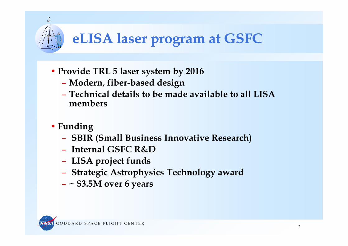
eLISA laser program at GSFCeLISA laser program at GSFC
• Provide TRL 5 laser system by 2016– Modern, fiber-based design– Technical details to be made available to all LISA members
• Funding – SBIR (Small Business Innovative Research) – Internal GSFC R&D– LISA project funds– Strategic Astrophysics Technology award– ~ $3.5M over 6 years
2

G O D D A R D S P A C E F L I G H T C E N T E R
GSFC LISA laser designGSFC LISA laser design
3
ECL + Pre-amplifier Power amplifier
ECL
Pump LD
Yb fiber
Pump LD
Yb fiberWDM TFB~10mW ~40mW~1.2W
MOPA designExternal Cavity Laser, fiber preamp, fiber amplifier
1064 nm wavelength2 Watt output
2 W
G O D D A R D S P A C E F L I G H T C E N T E R
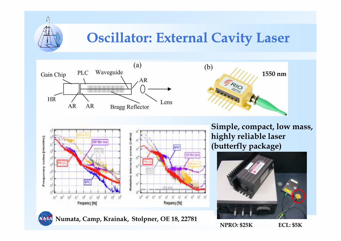
Oscillator: External Cavity Laser Oscillator: External Cavity Laser
Simple, compact, low mass, highly reliable laser (butterfly package)
Numata, Camp, Krainak, Stolpner, OE 18, 22781
1550 nm
NPRO: $25K ECL: $5K

G O D D A R D S P A C E F L I G H T C E N T E R
Packaging of ECL and PreampPackaging of ECL and Preamp
5
Redundant ECL and Preamplifier package
2 ECLs2 Preamp Diodes
10 cm x 5 cm x 1 cm50 mW output

G O D D A R D S P A C E F L I G H T C E N T E R
1550 nm ECL is space qualified1550 nm ECL is space qualified
6
Other tests:• Hermiticity• Gamma-ray exposure• Accelerated aging
Robust design suitable for space operation
G O D D A R D S P A C E F L I G H T C E N T E R
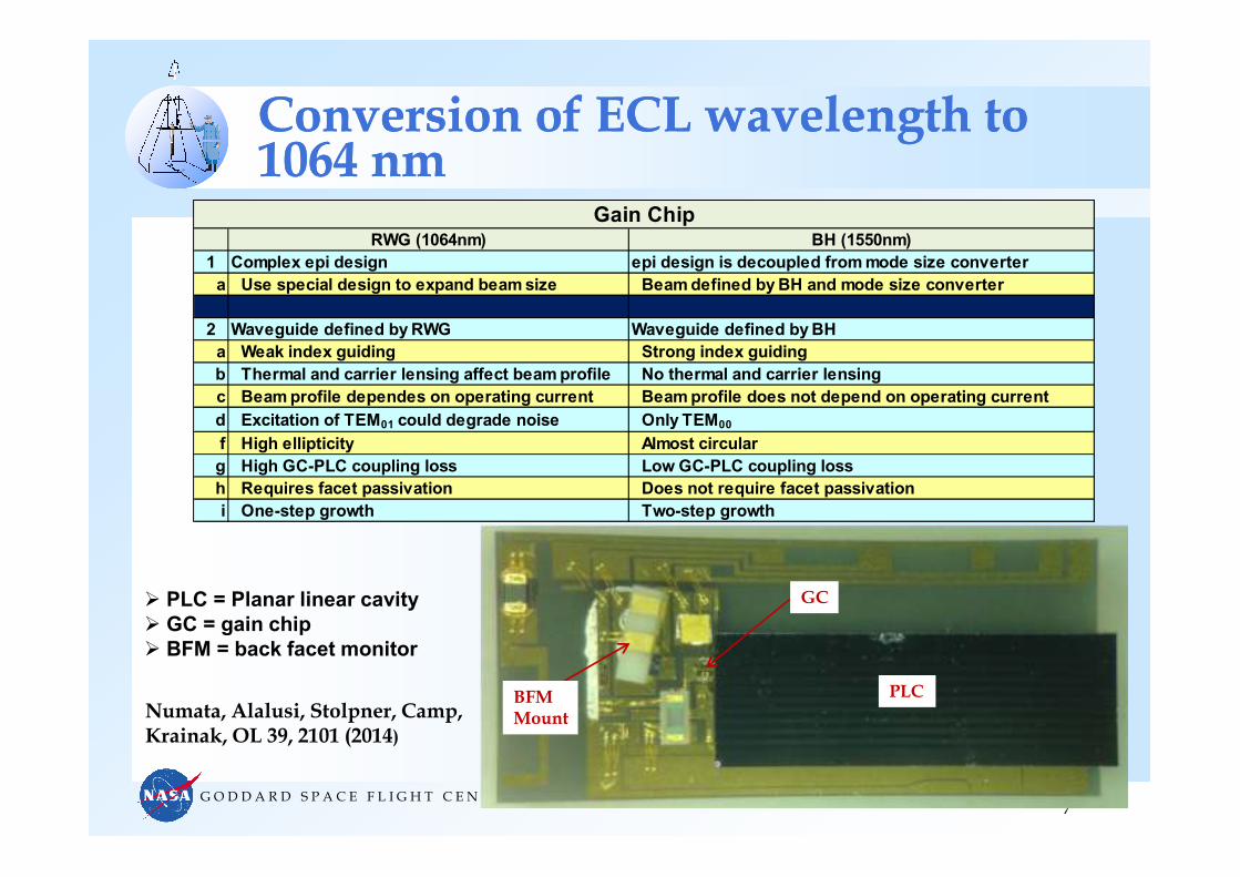
Conversion of ECL wavelength to 1064 nmConversion of ECL wavelength to 1064 nm
7
RWG (1064nm) BH (1550nm)
1 Complex epi design epi design is decoupled from mode size converter
a Use special design to expand beam size Beam defined by BH and mode size converter
2 Waveguide defined by RWG Waveguide defined by BH
a Weak index guiding Strong index guiding
b Thermal and carrier lensing affect beam profile No thermal and carrier lensing
c Beam profile dependes on operating current Beam profile does not depend on operating current
d Excitation of TEM01 could degrade noise Only TEM00
f High ellipticity Almost circular
g High GC-PLC coupling loss Low GC-PLC coupling loss
h Requires facet passivation Does not require facet passivation
i One-step growth Two-step growth
Gain Chip
PLC
GC
BFMMount
PLC = Planar linear cavity
GC = gain chip
BFM = back facet monitor
Numata, Alalusi, Stolpner, Camp, Krainak, OL 39, 2101 (2014)

G O D D A R D S P A C E F L I G H T C E N T E R
Frequency noise of world’s 1st 1064 nm ECL (in Butterfly package)Frequency noise of world’s 1st 1064 nm ECL (in Butterfly package)
8
Lowering phase noise: 1) optimize optical cavity reflectivity slope strong feedback low noise 2) optimize gain chip for low loss low noise3) select gain chip for lowest 1/f noise

G O D D A R D S P A C E F L I G H T C E N T E R
Frequency stabilization with iodineFrequency stabilization with iodine
• 1064nm PW-ECL + Yb fiber amp + Waveguide doubler
9
Satisfies the freq. noise requirement for eLISA at low frequency
Numata et al., Opt. Lett 39, 2101

G O D D A R D S P A C E F L I G H T C E N T E R
Frequency stabilizing the ECLFrequency stabilizing the ECL
10
External AOM as frequency actuator to suppress frequency noise at high frequency

G O D D A R D S P A C E F L I G H T C E N T E R
Frequency Modulation of ECL on laser chip (to be implemented) Frequency Modulation of ECL on laser chip (to be implemented)
Modulation of the effective refractive index inside the cavity, results in
frequency modulation of the external wavelength up to 100 MHz
FM section on the gain chip, separated from gain section by etching
10-15µµµµm Isolation > 300ΩΩΩΩ
SCH/MQW
Active Region
2000µµµµm
Ia+Im IbPLC Grating HRAR AR AR
Ia = bias current of section-a
Im = modulation current
G O D D A R D S P A C E F L I G H T C E N T E R
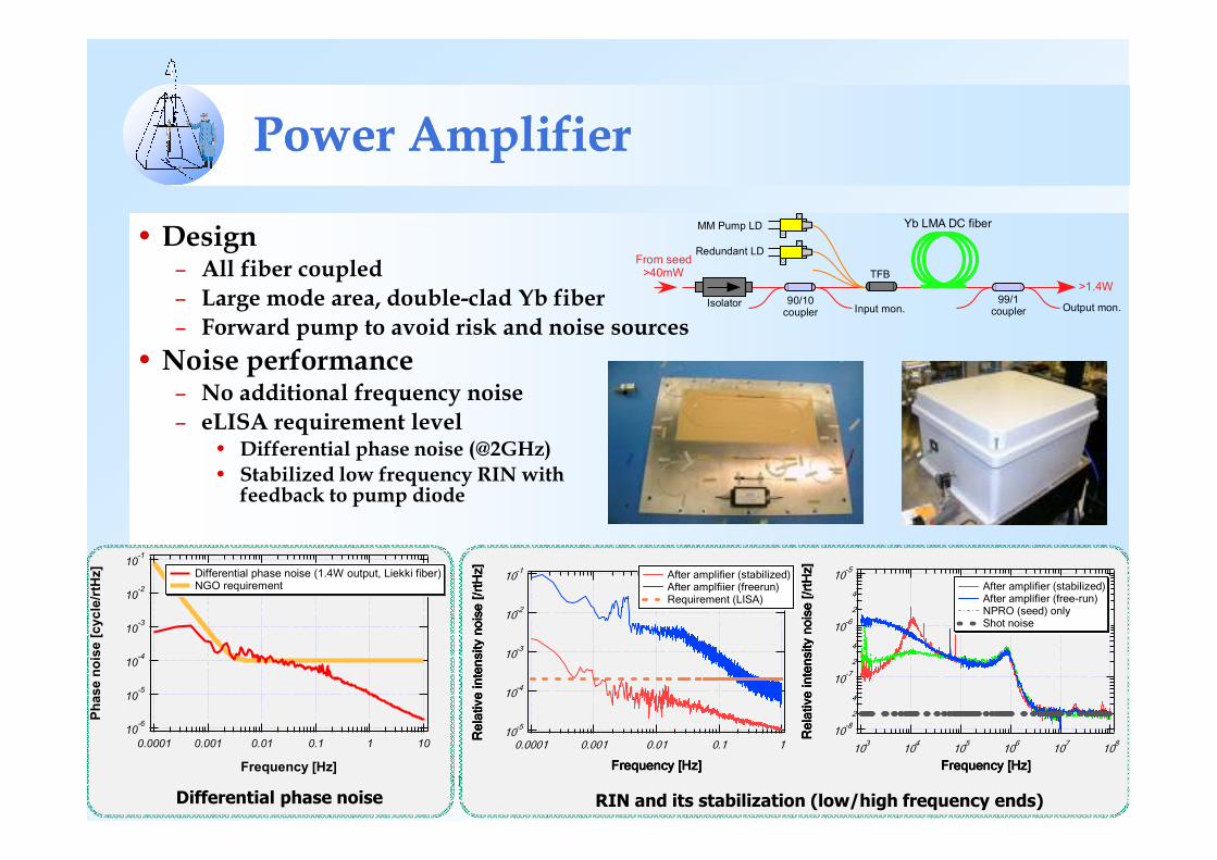
Power AmplifierPower Amplifier
• Design– All fiber coupled – Large mode area, double-clad Yb fiber– Forward pump to avoid risk and noise sources
• Noise performance– No additional frequency noise– eLISA requirement level
• Differential phase noise (@2GHz)• Stabilized low frequency RIN with
feedback to pump diode
10-6
10-5
10-4
10-3
10-2
10-1
Phase noise [cycle/rtHz]
0.0001 0.001 0.01 0.1 1 10
Frequency [Hz]
Differential phase noise (1.4W output, Liekki fiber) NGO requirement
MM Pump LD Yb LMA DC fiber
TFB
>1.4W
Redundant LD
IsolatorInput mon. Output mon.
90/10coupler
99/1coupler
From seed>40mW
10-8
2
4
10-7
2
4
10-6
2
4
10-5
Relative intensity noise [/rtH
z]
Relative intensity noise [/rtH
z]
Relative intensity noise [/rtH
z]
Relative intensity noise [/rtH
z]
103
104
105
106
107
108
Frequency [Hz]Frequency [Hz]Frequency [Hz]Frequency [Hz]
After amplifier (stabilized) After amplifier (free-run) NPRO (seed) only Shot noise
10-5
10-4
10-3
10-2
10-1
Relative intensity noise [/rtH
z]
Relative intensity noise [/rtH
z]
Relative intensity noise [/rtH
z]
Relative intensity noise [/rtH
z]
0.0001 0.001 0.01 0.1 1
Frequency [Hz]Frequency [Hz]Frequency [Hz]Frequency [Hz]
After amplifier (stabilized) After amplfiier (freerun) Requirement (LISA)
Differential phase noise RIN and its stabilization (low/high frequency ends)

G O D D A R D S P A C E F L I G H T C E N T E R
Planned Systems Tests for FY 2015Planned Systems Tests for FY 2015
13
1064 nm ECL oscillator, rebuilt power amplifierTemperature stabilized environmentTests: noise, accelerated aging, etc.
G O D D A R D S P A C E F L I G H T C E N T E R
Laser Development ScheduleLaser Development Schedule
• FY 2014 - 2015– Iterate design of 1064 nm ECL gain chip, planar cavity
• FY 2015– Laser system testing with 1064 nm ECL– Achieve final frequency noise performance
• FY 2016– Reliability testing of 1064 nm ECL• Low risk since same packaging as 1550 nm, also Eagleyard data indicates reliable 1064 nm gain chips
– Implement on-chip frequency modulation
14