DEVELOPMENT OF A PROJECT AND MANUFACTURE …€¦ · Keywords: joint prostheses, implants, titanium...
14
Proceedings of the 6th International Conference on Mechanics and Materials in Design, Editors: J.F. Silva Gomes & S.A. Meguid, P.Delgada/Azores, 26-30 July 2015 -1281- PAPER REF: 5567 DEVELOPMENT OF A PROJECT AND MANUFACTURE METHODOLOGY FOR TITANIUM ALLOYS JOINT PROSTHESES João Leite, Jorge Lino Alves (*) , Rui Neto, Teresa Duarte INEGI, Faculty of Engineering, University of Porto, Porto, Portugal (*) Email: [email protected] ABSTRACT This paper aims to study one methodology of project and manufacture of metallic joint prostheses by the investment casting process. Casting simulations of three different prostheses geometries were performed using ProCast software. Two distinct gating systems were simulated for a hip stem prostheses, and a third gating system was simulated for two knee prostheses components. The most promising system was selected to be produced by casting a Ti6Al4V alloy and the resulting parts were analysed in accordance to parameters specified by applicable standards. The parts obtained were evaluated in terms of metallurgical integrity and mechanical properties. Keywords: joint prostheses, implants, titanium alloys, investment casting, ProCast simulation. INTRODUCTION The increase of life expectancy presents distinct biomedical engineering challenges. This longer longevity of human body produces higher wear of bones, affecting movements, and consequently, higher probability of synovial joints deterioration is expected, resulting in significant loss of quality of life - osteoarthritis (L. Turek 1984, Baura 2011). Joint replacement is frequently performed on individuals with advanced osteoarthritis. Due to the highly invasive nature of the joint surgery procedure and its permanent modifications to the individual's bone structure, the production of orthopaedic prostheses is highly standardised so that quality parameters are consistently met. Titanium Ti6Al4V alloy is well suited for this type of replacement (Ratner et al. 2013, Leyens and Peters 2003, Davis 2003), and different technologies can be used for the production of orthopaedic prostheses. Forging and investment casting are the most popular methods for mass production, although other technologies such as additive manufacturing (Horáček et al. 2011, Duarte et al. 2011) or incremental forming (Lino et al. 2013) are nowadays starting to be used. The gating system is the part of the mould cavity which serves the purpose of conducting the flow of molten material from the pouring basin to the main cavities. Correct dimensioning of gating system is quite important, especially in the production of complex parts (Beeley 2001, Campbell 2011). A well dimensioned investment casting tree has a minimal chance of defects occurrence, such as shrinkage porosity within the parts, while the amount of material used for the gating system is minimised, when compared to the required material for the parts. Numerical simulation of gating and feeding systems improves and validates pattern assembly designs.To have more effective simulations, a good understanding of the solidification process of a specific casting is demanded. This means that learning to control the parameters
Transcript of DEVELOPMENT OF A PROJECT AND MANUFACTURE …€¦ · Keywords: joint prostheses, implants, titanium...
Proceedings of the 6th International Conference on Mechanics and Materials in Design,
Editors: J.F. Silva Gomes & S.A. Meguid, P.Delgada/Azores, 26-30 July 2015
-1281-
PAPER REF: 5567
DEVELOPMENT OF A PROJECT AND MANUFACTURE
METHODOLOGY FOR TITANIUM ALLOYS JOINT PROSTHESES
João Leite, Jorge Lino Alves(*), Rui Neto, Teresa Duarte
INEGI, Faculty of Engineering, University of Porto, Porto, Portugal (*)Email: [email protected]
ABSTRACT
This paper aims to study one methodology of project and manufacture of metallic joint
prostheses by the investment casting process. Casting simulations of three different prostheses
geometries were performed using ProCast software. Two distinct gating systems were
simulated for a hip stem prostheses, and a third gating system was simulated for two knee
prostheses components. The most promising system was selected to be produced by casting a
Ti6Al4V alloy and the resulting parts were analysed in accordance to parameters specified by
applicable standards. The parts obtained were evaluated in terms of metallurgical integrity and
mechanical properties.
Keywords: joint prostheses, implants, titanium alloys, investment casting, ProCast simulation.
INTRODUCTION
The increase of life expectancy presents distinct biomedical engineering challenges. This
longer longevity of human body produces higher wear of bones, affecting movements, and
consequently, higher probability of synovial joints deterioration is expected, resulting in
significant loss of quality of life - osteoarthritis (L. Turek 1984, Baura 2011).
Joint replacement is frequently performed on individuals with advanced osteoarthritis. Due to
the highly invasive nature of the joint surgery procedure and its permanent modifications to
the individual's bone structure, the production of orthopaedic prostheses is highly standardised
so that quality parameters are consistently met.
Titanium Ti6Al4V alloy is well suited for this type of replacement (Ratner et al. 2013, Leyens
and Peters 2003, Davis 2003), and different technologies can be used for the production of
orthopaedic prostheses. Forging and investment casting are the most popular methods for
mass production, although other technologies such as additive manufacturing (Horáček et al.
2011, Duarte et al. 2011) or incremental forming (Lino et al. 2013) are nowadays starting to
be used.
The gating system is the part of the mould cavity which serves the purpose of conducting the
flow of molten material from the pouring basin to the main cavities. Correct dimensioning of
gating system is quite important, especially in the production of complex parts (Beeley 2001,
Campbell 2011). A well dimensioned investment casting tree has a minimal chance of defects
occurrence, such as shrinkage porosity within the parts, while the amount of material used for
the gating system is minimised, when compared to the required material for the parts.
Numerical simulation of gating and feeding systems improves and validates pattern assembly
designs.To have more effective simulations, a good understanding of the solidification
process of a specific casting is demanded. This means that learning to control the parameters
Symposium_5
Design and Product Development
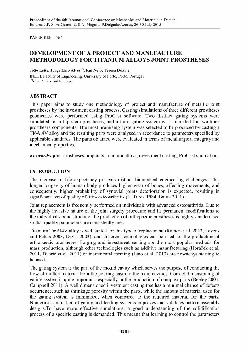
that affect the solidification can greatly influence the existence of shrinkage porosity. This
type of defect appears when there is a lack of liquid metal supply from
required to compensate the shrinkage suffered by the cooling metal. Fig. 1 exemplifies a
geometry in which the feeding of the right extremity is insufficient causing a hot spot while
the gating is already solid. To avoid shrinkage p
the parts and then it proceeds towards the pouring cup (ASM 1998).
Fig. 1 -Geometry prone to shrinkage porosity inside the
right extremity (adapted from
Titanium Ti6Al4V alloy is recommended for cast and wrought versions, with some minor
chemical composition changes to suit the particular manufacturing process (ISO does not
have a standard for casted Ti6Al4V). This paper presents and d
details of investment cast Ti6Al4V implants in accordance to ASTM standards (ASTM 2009).
EXPERIMENTAL WORK
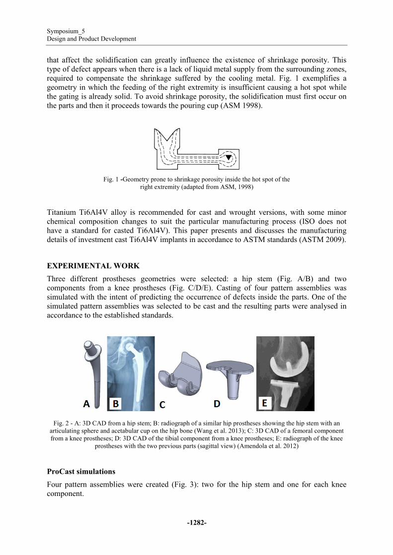
Three different prostheses geometries were selected: a hip stem
components from a knee prostheses
simulated with the intent of predicting the occurrence of defects inside the parts. One of the
simulated pattern assemblies was selected to be cast and the resulting parts were analysed in
accordance to the established standards.
Fig. 2 - A: 3D CAD from a hip stem; B: radiograph of a similar hip prostheses showing the hip stem with an
articulating sphere and acetabular cup on the hip bone
from a knee prostheses; D: 3D CAD of the tibial
prostheses with the two previous parts (sagittal view)
ProCast simulations
Four pattern assemblies were created (Fig. 3): two for the hip stem and one for ea
component.
-1282-
that affect the solidification can greatly influence the existence of shrinkage porosity. This
type of defect appears when there is a lack of liquid metal supply from the surrounding zones,
required to compensate the shrinkage suffered by the cooling metal. Fig. 1 exemplifies a
geometry in which the feeding of the right extremity is insufficient causing a hot spot while
the gating is already solid. To avoid shrinkage porosity, the solidification must first occur on
the parts and then it proceeds towards the pouring cup (ASM 1998).
Geometry prone to shrinkage porosity inside the hot spot of the
right extremity (adapted from ASM, 1998)
Titanium Ti6Al4V alloy is recommended for cast and wrought versions, with some minor
chemical composition changes to suit the particular manufacturing process (ISO does not
have a standard for casted Ti6Al4V). This paper presents and discusses the manufacturing
details of investment cast Ti6Al4V implants in accordance to ASTM standards (ASTM 2009).
Three different prostheses geometries were selected: a hip stem (Fig.
components from a knee prostheses (Fig. C/D/E). Casting of four pattern
simulated with the intent of predicting the occurrence of defects inside the parts. One of the
simulated pattern assemblies was selected to be cast and the resulting parts were analysed in
accordance to the established standards.
A: 3D CAD from a hip stem; B: radiograph of a similar hip prostheses showing the hip stem with an
sphere and acetabular cup on the hip bone (Wang et al. 2013); C: 3D CAD of
from a knee prostheses; D: 3D CAD of the tibial component from a knee prostheses; E: radiograph of the knee
prostheses with the two previous parts (sagittal view) (Amendola et al. 2012
Four pattern assemblies were created (Fig. 3): two for the hip stem and one for ea
that affect the solidification can greatly influence the existence of shrinkage porosity. This
the surrounding zones,
required to compensate the shrinkage suffered by the cooling metal. Fig. 1 exemplifies a
geometry in which the feeding of the right extremity is insufficient causing a hot spot while
orosity, the solidification must first occur on
hot spot of the
Titanium Ti6Al4V alloy is recommended for cast and wrought versions, with some minor
chemical composition changes to suit the particular manufacturing process (ISO does not
iscusses the manufacturing
details of investment cast Ti6Al4V implants in accordance to ASTM standards (ASTM 2009).
Fig. A/B) and two
Casting of four pattern assemblies was
simulated with the intent of predicting the occurrence of defects inside the parts. One of the
simulated pattern assemblies was selected to be cast and the resulting parts were analysed in
A: 3D CAD from a hip stem; B: radiograph of a similar hip prostheses showing the hip stem with an
; C: 3D CAD of a femoral component
component from a knee prostheses; E: radiograph of the knee
Amendola et al. 2012)
Four pattern assemblies were created (Fig. 3): two for the hip stem and one for each knee

Proceedings of the 6th International Conference on Mechanics and Materials in Design,
Editors: J.F. Silva Gomes & S.A. Meguid, P.Delgada/Azores, 26
Fig. 2 - 3D CAD models of the simulated pattern cluster assemblies; C1: 6 hip stems
hip stems (upside arrangement), C3
Each geometry was modelled using SolidWorks software and then converted to IGS format to
be processed on ProCast. The chosen parameters for the simulation are indicated on Table 1.
The IHTC (interface heat transfer content) quantifies the heat transfer between
of the ceramic shell and the exterior surrounding environment. The chosen cooling process
was air and no chills or insulation devices were used. The shell layers were modelled with
tetrahedral elements (Fig. 4).
Part Material
Metal alloy Ti6Al4V
Facecoat Full yttria
Backup Full Alumina
Fig. 4 - Modelling of ceramic shell layers on C2 geometry; A: no shell layers; B: 2mm facecoat layer; C: 5mm
For each geometry (C1 to C4), fluid velocity (pouring), solidification time (solidification) and
shrinkage porosity (porosity) occurrence were simulated.
Proceedings of the 6th International Conference on Mechanics and Materials in Design,
Editors: J.F. Silva Gomes & S.A. Meguid, P.Delgada/Azores, 26-30 July 2015
-1283-
models of the simulated pattern cluster assemblies; C1: 6 hip stems (down arrangement)
hip stems (upside arrangement), C3: 8 tibial knee components, C4: 6 femoral knee components
geometry was modelled using SolidWorks software and then converted to IGS format to
be processed on ProCast. The chosen parameters for the simulation are indicated on Table 1.
The IHTC (interface heat transfer content) quantifies the heat transfer between
of the ceramic shell and the exterior surrounding environment. The chosen cooling process
was air and no chills or insulation devices were used. The shell layers were modelled with
Table 1 - ProCast simulation parameters
Temperature
[⁰C] Thickness
[mm]
IHTC
[W/m2K]
1750 - casting -
900
1100 – Pre-
heating 2
1100 – Pre-
heating 5
Modelling of ceramic shell layers on C2 geometry; A: no shell layers; B: 2mm facecoat layer; C: 5mm
backup
For each geometry (C1 to C4), fluid velocity (pouring), solidification time (solidification) and
shrinkage porosity (porosity) occurrence were simulated.
(down arrangement), C2: 6
moral knee components
geometry was modelled using SolidWorks software and then converted to IGS format to
be processed on ProCast. The chosen parameters for the simulation are indicated on Table 1.
The IHTC (interface heat transfer content) quantifies the heat transfer between the inner part
of the ceramic shell and the exterior surrounding environment. The chosen cooling process
was air and no chills or insulation devices were used. The shell layers were modelled with
Type of
cooling
30 minutes
inside furnace
200 mbar
Argon + Air
Modelling of ceramic shell layers on C2 geometry; A: no shell layers; B: 2mm facecoat layer; C: 5mm
For each geometry (C1 to C4), fluid velocity (pouring), solidification time (solidification) and
Symposium_5
Design and Product Development
-1284-
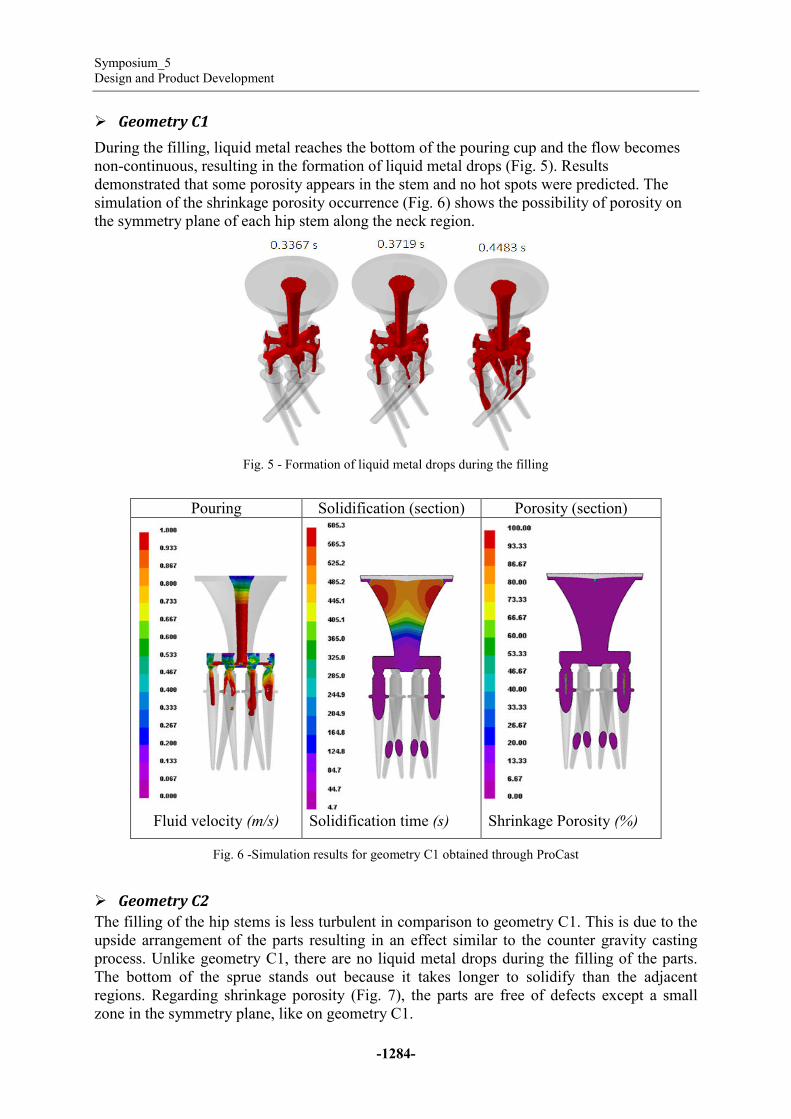
� Geometry C1
During the filling, liquid metal reaches the bottom of the pouring cup and the flow becomes
non-continuous, resulting in the formation of liquid metal drops (Fig. 5). Results
demonstrated that some porosity appears in the stem and no hot spots were predicted. The
simulation of the shrinkage porosity occurrence (Fig. 6) shows the possibility of porosity on
the symmetry plane of each hip stem along the neck region.
Fig. 5 - Formation of liquid metal drops during the filling
Pouring Solidification (section) Porosity (section)
Fluid velocity (m/s) Solidification time (s) Shrinkage Porosity (%)
Fig. 6 -Simulation results for geometry C1 obtained through ProCast
� Geometry C2
The filling of the hip stems is less turbulent in comparison to geometry C1. This is due to the
upside arrangement of the parts resulting in an effect similar to the counter gravity casting
process. Unlike geometry C1, there are no liquid metal drops during the filling of the parts.
The bottom of the sprue stands out because it takes longer to solidify than the adjacent
regions. Regarding shrinkage porosity (Fig. 7), the parts are free of defects except a small
zone in the symmetry plane, like on geometry C1.
Proceedings of the 6th International Conference on Mechanics and Materials in Design,
Editors: J.F. Silva Gomes & S.A. Meguid, P.Delgada/Azores, 26-30 July 2015
-1285-
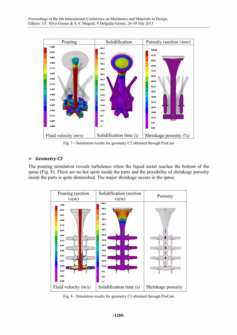
Pouring Solidification Porosity (section view)
Fluid velocity (m/s) Solidification time (s) Shrinkage porosity (%)
Fig. 7 - Simulation results for geometry C2 obtained through ProCast
� Geometry C3
The pouring simulation reveals turbulence when the liquid metal reaches the bottom of the
sprue (Fig. 8). There are no hot spots inside the parts and the possibility of shrinkage porosity
inside the parts is quite diminished. The major shrinkage occurs in the sprue.
Pouring (section
view)
Solidification (section
view) Porosity
Fluid velocity (m/s) Solidification time (s) Shrinkage porosity
Fig. 8 - Simulation results for geometry C3 obtained through ProCast

Symposium_5
Design and Product Development
-1286-
� Geometry C4
This simulation reveals similar results to the ones from the previous geometry because the
parts are arranged in an identical manner. The main difference lies in the gating between the
part and the sprue. In geometry C4, the implants are attached to the sprue by two channels.
Regarding the shrinkage, most of the porosity is predicted in the sprue while there is the
possibility of occurrence of porosity in the two most massive zones inside the part, meaning
that they have a large modulus (Fig. 9).
Pouring Pouring (section
view) Porosity
Fluid velocity (m/s) Fluid velocity (m/s) Shrinkage porosity
Fig. 9 - Simulation results for geometry C4 obtained through ProCast
From the 4 simulated geometries, C3 (knee tibial component), due to less forecast shrinkage
porosity, was selected to be produced.
Manufacture of wax models
The wax pattern was part of an investment casting production of tibial knee components. As
several identical tibial knee parts were needed to create a complete pattern assembly, a wax
injection mould tool was developed.
The selected method was additive manufacturing of a master pattern, and then the
corresponding moulding cavity was obtained using polyurethane resins filled with aluminium
powders.
To produce the master pattern, a 3D CAD file was obtained from a commercial prosthesis
through a 3D scanner (Fig. 10). The mould for wax injection requires two parts that were
made separately, meaning that the CAD for the master pattern was split in two parts. Two
holes for alignment pins were added to the geometry (Fig. 11A), and the parting plane was
chosen assuring that any undercuts were present.
Proceedings of the 6th International Conference on Mechanics and Materials in Design,
Editors: J.F. Silva Gomes & S.A. Meguid, P.Delgada/Azores, 26
Fig. 10
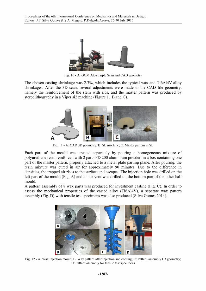
The chosen casting shrinkage was 2.3%, which includes the typical wax and Ti6Al4V alloy
shrinkages. After the 3D scan, several adjustments were made to the CAD file geometry,
namely the reinforcement of the stem with ribs, and the master pattern was produc
stereolithography in a Viper si2 machine
Fig. 11 - A: CAD 3D geometry; B: SL machine; C: Master pattern in SL
Each part of the mould was created separately by pouring a homogeneous mixture of
polyurethane resin reinforced with 2 parts PD 200 aluminium powder, in a box containing one
part of the master pattern, properly attached to a metal plate parting plane. Afte
resin mixture was cured in air for approximately 90 minutes. Due to the difference in
densities, the trapped air rises to the surface and escapes. The injection hole was drilled on the
left part of the mould (Fig. A) and an air vent was drilled on the bottom
mould.
A pattern assembly of 8 wax parts was produced for investment casting (
assess the mechanical properties of the cast
assembly (Fig. D) with tensile test specimens was also
Fig. 12 - A: Wax injection mould; B: Wax pattern after injection and cooling; C: Pattern assembly C3 geometry;
D: Pa
Proceedings of the 6th International Conference on Mechanics and Materials in Design,
Editors: J.F. Silva Gomes & S.A. Meguid, P.Delgada/Azores, 26-30 July 2015
-1287-
10 - A: GOM Atos Triple Scan and CAD geometry
The chosen casting shrinkage was 2.3%, which includes the typical wax and Ti6Al4V alloy
shrinkages. After the 3D scan, several adjustments were made to the CAD file geometry,
namely the reinforcement of the stem with ribs, and the master pattern was produc
a Viper si2 machine (Figure 11 B and C).
A: CAD 3D geometry; B: SL machine; C: Master pattern in SL
Each part of the mould was created separately by pouring a homogeneous mixture of
polyurethane resin reinforced with 2 parts PD 200 aluminium powder, in a box containing one
part of the master pattern, properly attached to a metal plate parting plane. Afte
resin mixture was cured in air for approximately 90 minutes. Due to the difference in
densities, the trapped air rises to the surface and escapes. The injection hole was drilled on the
A) and an air vent was drilled on the bottom part of the other half
A pattern assembly of 8 wax parts was produced for investment casting (Fig.
assess the mechanical properties of the casted alloy (Ti6Al4V), a separate wax pattern
ile test specimens was also produced (Silva Gomes 2014
A: Wax injection mould; B: Wax pattern after injection and cooling; C: Pattern assembly C3 geometry;
D: Pattern assembly for tensile test specimens
The chosen casting shrinkage was 2.3%, which includes the typical wax and Ti6Al4V alloy
shrinkages. After the 3D scan, several adjustments were made to the CAD file geometry,
namely the reinforcement of the stem with ribs, and the master pattern was produced by
A: CAD 3D geometry; B: SL machine; C: Master pattern in SL
Each part of the mould was created separately by pouring a homogeneous mixture of
polyurethane resin reinforced with 2 parts PD 200 aluminium powder, in a box containing one
part of the master pattern, properly attached to a metal plate parting plane. After pouring, the
resin mixture was cured in air for approximately 90 minutes. Due to the difference in
densities, the trapped air rises to the surface and escapes. The injection hole was drilled on the
part of the other half
Fig. C). In order to
alloy (Ti6Al4V), a separate wax pattern
Silva Gomes 2014).
A: Wax injection mould; B: Wax pattern after injection and cooling; C: Pattern assembly C3 geometry;

Symposium_5
Design and Product Development
Manufacture of ceramic shell (mould)
The assembling tree was dipped in an yttria based slurry. To increase the facecoat’s strength,
alumina based backup layers were deposited. Each layer was achieved by dipping the
assembly in a spinning container filled with the slurry (Fig. 13A) so that the ceramic particles
are able to adhere afterwards. Several layers were deposited to increase the strength of the
shell. After drying the ceramic shell (Fig. 13B), the wax
firing process and sintering was performed at 1450
Fig. 13 - A: Application of slurries; B: Fully sintered ceramic shell.
Casting the knee prostheses
Ti6Al4V was selected for casting this part. Table 2 presents the chemical composition of the
casted alloy and compares it with the ones specified by different standards. It is important to
refer that although the equipment
analysis is unable to detect oxygen, nitrogen and hydrogen, all the other elements are within
the specifications.
Table
Standard Alloy
ASTM F1108(a)
Cast 5.5
ASTM F136(b)
Wrought
ELI 5.5
ISO 5832-3(c)
Wrought 5.5
Experimental
work Cast
(a) - (ASTM 2009); (b) - (ASTM 2013b); (c) - (ISO 1996
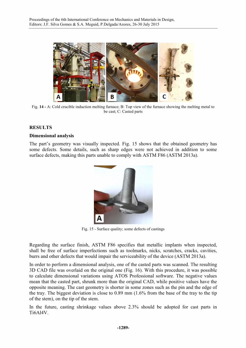
After preheating the ceramic shell at 1100 ºC for 1 hour, Ti6Al4V was
using a cold crucible induction melting (Fig. 14). Argon was used to clean and control the
atmosphere inside the sealed chambers containing the crucible and the ceramic shell.
After cooling and shake out, one realized that the ceramic she
although the required amount of Ti6Al4V to fill the shell was the same as the limit of the
crucible (1.6kg). Four complete parts were cut from the tree and blasted so that small surface
imperfections were removed.
-1288-
Manufacture of ceramic shell (mould)
The assembling tree was dipped in an yttria based slurry. To increase the facecoat’s strength,
alumina based backup layers were deposited. Each layer was achieved by dipping the
assembly in a spinning container filled with the slurry (Fig. 13A) so that the ceramic particles
are able to adhere afterwards. Several layers were deposited to increase the strength of the
shell. After drying the ceramic shell (Fig. 13B), the wax was removed at 1100
firing process and sintering was performed at 1450⁰C, for 1 hour.
A: Application of slurries; B: Fully sintered ceramic shell.
Ti6Al4V was selected for casting this part. Table 2 presents the chemical composition of the
casted alloy and compares it with the ones specified by different standards. It is important to
refer that although the equipment (model Spectromax F, from Spectro)
analysis is unable to detect oxygen, nitrogen and hydrogen, all the other elements are within
Table 2 - Chemical compositions of Ti6Al4V
Al V Fe O C N
5.5 - 6.75 3.5 - 4.5 <0.20 <0.20 <0.10 <0.05
5.5 - 6.50 3.5 - 4.5 <0.25 <0.13 <0.08 <0.05
5.5 - 6.75 3.5 - 4.5 <0.3 <0.2 <0.08 <0.05
6.38 3.88 0.048 - 0.053
ISO 1996)
After preheating the ceramic shell at 1100 ºC for 1 hour, Ti6Al4V was
using a cold crucible induction melting (Fig. 14). Argon was used to clean and control the
atmosphere inside the sealed chambers containing the crucible and the ceramic shell.
After cooling and shake out, one realized that the ceramic shell was not completely filled,
although the required amount of Ti6Al4V to fill the shell was the same as the limit of the
crucible (1.6kg). Four complete parts were cut from the tree and blasted so that small surface
The assembling tree was dipped in an yttria based slurry. To increase the facecoat’s strength,
alumina based backup layers were deposited. Each layer was achieved by dipping the pattern
assembly in a spinning container filled with the slurry (Fig. 13A) so that the ceramic particles
are able to adhere afterwards. Several layers were deposited to increase the strength of the
was removed at 1100⁰C by the flash-
A: Application of slurries; B: Fully sintered ceramic shell.
Ti6Al4V was selected for casting this part. Table 2 presents the chemical composition of the
casted alloy and compares it with the ones specified by different standards. It is important to
used for chemical
analysis is unable to detect oxygen, nitrogen and hydrogen, all the other elements are within
N H Others
<0.05 <0.015 -
<0.05 <0.012 -
<0.05 <0.015 -
- - -
After preheating the ceramic shell at 1100 ºC for 1 hour, Ti6Al4V was poured at 1650 ºC
using a cold crucible induction melting (Fig. 14). Argon was used to clean and control the
atmosphere inside the sealed chambers containing the crucible and the ceramic shell.
ll was not completely filled,
although the required amount of Ti6Al4V to fill the shell was the same as the limit of the
crucible (1.6kg). Four complete parts were cut from the tree and blasted so that small surface
Proceedings of the 6th International Conference on Mechanics and Materials in Design,
Editors: J.F. Silva Gomes & S.A. Meguid, P.Delgada/Azores, 26
Fig. 14 - A: Cold crucible induction melting furnace; B: Top view of the furnace
RESULTS
Dimensional analysis
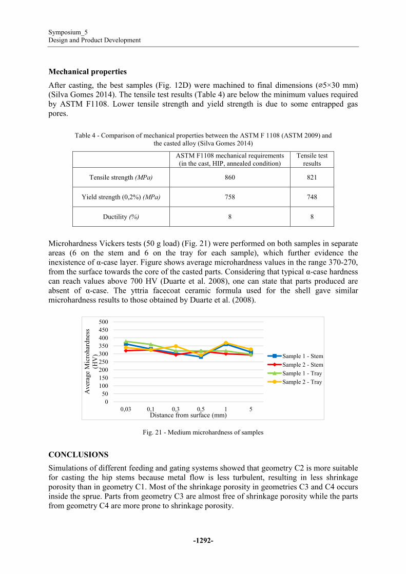
The part’s geometry was visually inspected. Fig. 15 shows that the obtained geometry has
some defects. Some details, such as sharp edges were not achieved in addition to some
surface defects, making this parts unable to comply with ASTM F86 (ASTM 2013a).
Fig.
Regarding the surface finish, ASTM F86 s
shall be free of surface imperfections such as toolmarks, nicks, scratches, cracks, cavities,
burrs and other defects that would impair the serviceability of the device
In order to perform a dimensional analysis, one of the casted parts was scanned. The resulting
3D CAD file was overlaid on the original one
to calculate dimensional variations using ATOS
mean that the casted part, shrunk more than the original CAD, while positive values have the
opposite meaning. The cast geometry is shorter in some zones such as the pin and the edge of
the tray. The biggest deviation is close to 0.89 mm
of the stem), on the tip of the stem.
In the future, casting shrinkage values above 2.3% should be adopted for cast parts in
Ti6Al4V.
Proceedings of the 6th International Conference on Mechanics and Materials in Design,
Editors: J.F. Silva Gomes & S.A. Meguid, P.Delgada/Azores, 26-30 July 2015
-1289-
A: Cold crucible induction melting furnace; B: Top view of the furnace showing
be cast; C: Casted parts
The part’s geometry was visually inspected. Fig. 15 shows that the obtained geometry has
defects. Some details, such as sharp edges were not achieved in addition to some
surface defects, making this parts unable to comply with ASTM F86 (ASTM 2013a).
Fig. 15 - Surface quality; some defects of castings
Regarding the surface finish, ASTM F86 specifies that metallic implants when inspected,
shall be free of surface imperfections such as toolmarks, nicks, scratches, cracks, cavities,
burrs and other defects that would impair the serviceability of the device (ASTM 2013a)
In order to perform a dimensional analysis, one of the casted parts was scanned. The resulting
3D CAD file was overlaid on the original one (Fig. 16). With this procedure, it was possible
to calculate dimensional variations using ATOS Professional software. The negative values
mean that the casted part, shrunk more than the original CAD, while positive values have the
opposite meaning. The cast geometry is shorter in some zones such as the pin and the edge of
tion is close to 0.89 mm (1.6% from the base of the tray to the tip
, on the tip of the stem.
In the future, casting shrinkage values above 2.3% should be adopted for cast parts in
showing the melting metal to
The part’s geometry was visually inspected. Fig. 15 shows that the obtained geometry has
defects. Some details, such as sharp edges were not achieved in addition to some
surface defects, making this parts unable to comply with ASTM F86 (ASTM 2013a).
pecifies that metallic implants when inspected,
shall be free of surface imperfections such as toolmarks, nicks, scratches, cracks, cavities,
(ASTM 2013a).
In order to perform a dimensional analysis, one of the casted parts was scanned. The resulting
With this procedure, it was possible
Professional software. The negative values
mean that the casted part, shrunk more than the original CAD, while positive values have the
opposite meaning. The cast geometry is shorter in some zones such as the pin and the edge of
(1.6% from the base of the tray to the tip
In the future, casting shrinkage values above 2.3% should be adopted for cast parts in

Symposium_5
Design and Product Development
Fig. 16 - Dimensional deviation from the cast part i
Microstructural analysis
Two samples were cut along the
prepared for microstructural analysis
techniques. Kroll’s reagent was used to reveal the microstructure.
visible pores on both samples.
Fig. 17
Sample 2 exhibits grain size in the range of
(Fig. B and Fig. C), a lighter α phase and a darker β phase. The morphology is acicular and
some pores (average diameter size 200 µm)
were detected (Fig. ). From Fig.
The microstructure of Ti6Al4V castings is not standardized, however considering the wrought
version, the microstructure should be in accordance with Table 3 and Fig. 20.
-1290-
Dimensional deviation from the cast part in comparison to the original CAD (tray 70mm
long and stem 55mm high)
Two samples were cut along the symmetry plane from different casted parts and they were
prepared for microstructural analysis (Fig. 17) using conventional metallographic preparation
Kroll’s reagent was used to reveal the microstructure. At first sight, there
visible pores on both samples.
17 - Samples prepared for microstructural analysis
Sample 2 exhibits grain size in the range of 1-2 mm (Fig. A). Two different phases are
, a lighter α phase and a darker β phase. The morphology is acicular and
(average diameter size 200 µm) resulting from entrapped gas during solidification
Fig. A it is unnoticeable the existence of a surface α
The microstructure of Ti6Al4V castings is not standardized, however considering the wrought
rostructure should be in accordance with Table 3 and Fig. 20.
n comparison to the original CAD (tray 70mm
from different casted parts and they were
using conventional metallographic preparation
At first sight, there were no
A). Two different phases are visible
, a lighter α phase and a darker β phase. The morphology is acicular and
resulting from entrapped gas during solidification
A it is unnoticeable the existence of a surface α-case layer.
The microstructure of Ti6Al4V castings is not standardized, however considering the wrought
rostructure should be in accordance with Table 3 and Fig. 20.

Proceedings of the 6th International Conference on Mechanics and Materials in Design,
Editors: J.F. Silva Gomes & S.A. Meguid, P.Delgada/Azores, 26
Fig. 18 - Microstructures of sample 2; A: Optic microscopy with metric ruler (mm) for size comparison; B and
Fig. 19 - Micrographs showing gas pores; A: sample 1;
Table
Standard Phases
ISO 5832-3 (a)
alpha + beta globular
ASTM F136 (b)
Fine dispersion of
beta phases; no coarse
elongated alpha platelets(a) (ISO 1996); (b) (ASTM 2013b)
Fig. 20 - Microstructure A3 from a typical alpha+beta titanium rolled bar sample from ISO 20160; the other
microstructures are similar
Proceedings of the 6th International Conference on Mechanics and Materials in Design,
Editors: J.F. Silva Gomes & S.A. Meguid, P.Delgada/Azores, 26-30 July 2015
-1291-
Microstructures of sample 2; A: Optic microscopy with metric ruler (mm) for size comparison; B and
C: polarized micrographs
Micrographs showing gas pores; A: sample 1; B and C: sample 2
Table 3 - Microstructure of wrought Ti6Al4V alloy
Inclusion content Observations
lpha + beta globular Free of optically
visible inclusions
at ×200
Shall correspond to
photomicrographs A1 to A9 from
ISO 20160 (see
annealed state
Fine dispersion of alpha +
beta phases; no coarse
gated alpha platelets
Unspecified No alpha case
Microstructure A3 from a typical alpha+beta titanium rolled bar sample from ISO 20160; the other
microstructures are similar with only a change in grain size (ISO 2006
50µµµµm
Microstructures of sample 2; A: Optic microscopy with metric ruler (mm) for size comparison; B and
B and C: sample 2
Shall correspond to
photomicrographs A1 to A9 from
ISO 20160 (see Fig. ) when in the
Microstructure A3 from a typical alpha+beta titanium rolled bar sample from ISO 20160; the other
ISO 2006).
Symposium_5
Design and Product Development
-1292-
Mechanical properties
After casting, the best samples (Fig. 12D) were machined to final dimensions (⌀5×30 mm)
(Silva Gomes 2014). The tensile test results (Table 4) are below the minimum values required
by ASTM F1108. Lower tensile strength and yield strength is due to some entrapped gas
pores.
Table 4 - Comparison of mechanical properties between the ASTM F 1108 (ASTM 2009) and
the casted alloy (Silva Gomes 2014)
ASTM F1108 mechanical requirements
(in the cast, HIP, annealed condition)
Tensile test
results
Tensile strength (MPa) 860 821
Yield strength (0,2%) (MPa) 758 748
Ductility (%) 8 8
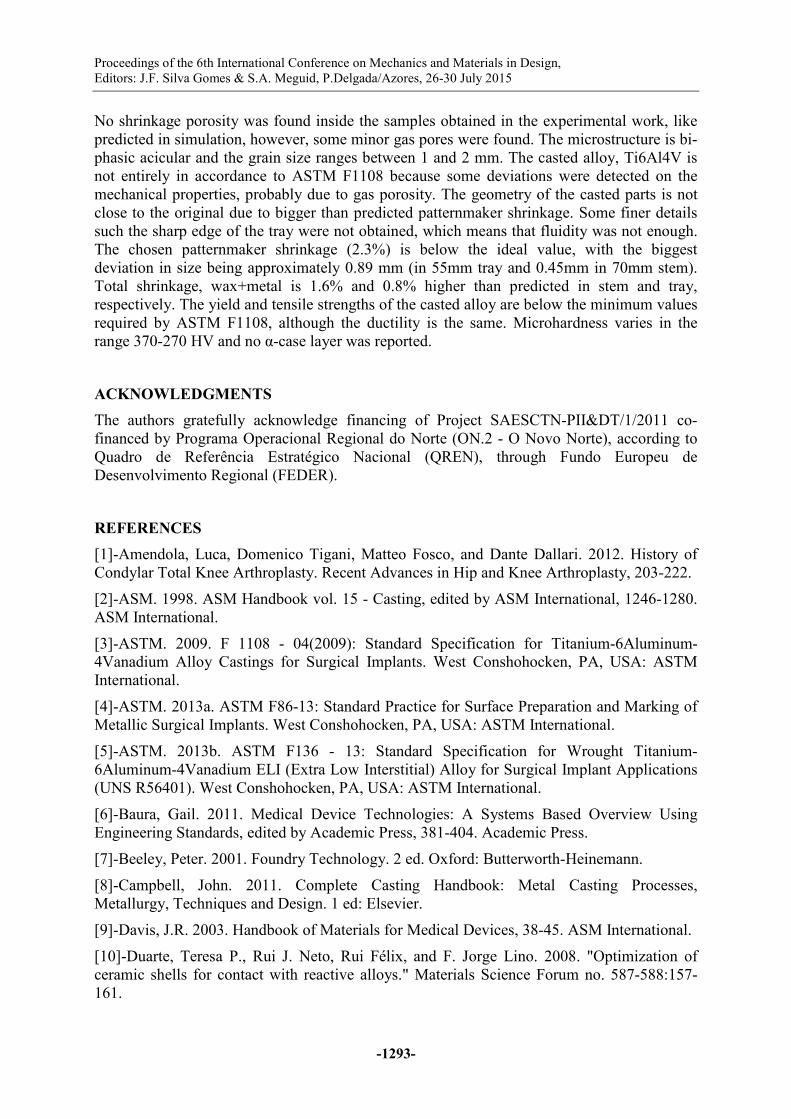
Microhardness Vickers tests (50 g load) (Fig. 21) were performed on both samples in separate
areas (6 on the stem and 6 on the tray for each sample), which further evidence the
inexistence of α-case layer. Figure shows average microhardness values in the range 370-270,
from the surface towards the core of the casted parts. Considering that typical α-case hardness
can reach values above 700 HV (Duarte et al. 2008), one can state that parts produced are
absent of α-case. The yttria facecoat ceramic formula used for the shell gave similar
microhardness results to those obtained by Duarte et al. (2008).
Fig. 21 - Medium microhardness of samples
CONCLUSIONS
Simulations of different feeding and gating systems showed that geometry C2 is more suitable
for casting the hip stems because metal flow is less turbulent, resulting in less shrinkage
porosity than in geometry C1. Most of the shrinkage porosity in geometries C3 and C4 occurs
inside the sprue. Parts from geometry C3 are almost free of shrinkage porosity while the parts
from geometry C4 are more prone to shrinkage porosity.
0
50
100
150
200
250
300
350
400
450
500
0,03 0,1 0,3 0,5 1 5
Aver
age
Mic
rohar
dnes
s
(HV
)
Distance from surface (mm)
Sample 1 - Stem
Sample 2 - Stem
Sample 1 - Tray
Sample 2 - Tray
Proceedings of the 6th International Conference on Mechanics and Materials in Design,
Editors: J.F. Silva Gomes & S.A. Meguid, P.Delgada/Azores, 26-30 July 2015
-1293-
No shrinkage porosity was found inside the samples obtained in the experimental work, like
predicted in simulation, however, some minor gas pores were found. The microstructure is bi-
phasic acicular and the grain size ranges between 1 and 2 mm. The casted alloy, Ti6Al4V is
not entirely in accordance to ASTM F1108 because some deviations were detected on the
mechanical properties, probably due to gas porosity. The geometry of the casted parts is not
close to the original due to bigger than predicted patternmaker shrinkage. Some finer details
such the sharp edge of the tray were not obtained, which means that fluidity was not enough.
The chosen patternmaker shrinkage (2.3%) is below the ideal value, with the biggest
deviation in size being approximately 0.89 mm (in 55mm tray and 0.45mm in 70mm stem).
Total shrinkage, wax+metal is 1.6% and 0.8% higher than predicted in stem and tray,
respectively. The yield and tensile strengths of the casted alloy are below the minimum values
required by ASTM F1108, although the ductility is the same. Microhardness varies in the
range 370-270 HV and no α-case layer was reported.
ACKNOWLEDGMENTS
The authors gratefully acknowledge financing of Project SAESCTN-PII&DT/1/2011 co-
financed by Programa Operacional Regional do Norte (ON.2 - O Novo Norte), according to
Quadro de Referência Estratégico Nacional (QREN), through Fundo Europeu de
Desenvolvimento Regional (FEDER).
REFERENCES
[1]-Amendola, Luca, Domenico Tigani, Matteo Fosco, and Dante Dallari. 2012. History of
Condylar Total Knee Arthroplasty. Recent Advances in Hip and Knee Arthroplasty, 203-222.
[2]-ASM. 1998. ASM Handbook vol. 15 - Casting, edited by ASM International, 1246-1280.
ASM International.
[3]-ASTM. 2009. F 1108 - 04(2009): Standard Specification for Titanium-6Aluminum-
4Vanadium Alloy Castings for Surgical Implants. West Conshohocken, PA, USA: ASTM
International.
[4]-ASTM. 2013a. ASTM F86-13: Standard Practice for Surface Preparation and Marking of
Metallic Surgical Implants. West Conshohocken, PA, USA: ASTM International.
[5]-ASTM. 2013b. ASTM F136 - 13: Standard Specification for Wrought Titanium-
6Aluminum-4Vanadium ELI (Extra Low Interstitial) Alloy for Surgical Implant Applications
(UNS R56401). West Conshohocken, PA, USA: ASTM International.
[6]-Baura, Gail. 2011. Medical Device Technologies: A Systems Based Overview Using
Engineering Standards, edited by Academic Press, 381-404. Academic Press.
[7]-Beeley, Peter. 2001. Foundry Technology. 2 ed. Oxford: Butterworth-Heinemann.
[8]-Campbell, John. 2011. Complete Casting Handbook: Metal Casting Processes,
Metallurgy, Techniques and Design. 1 ed: Elsevier.
[9]-Davis, J.R. 2003. Handbook of Materials for Medical Devices, 38-45. ASM International.
[10]-Duarte, Teresa P., Rui J. Neto, Rui Félix, and F. Jorge Lino. 2008. "Optimization of
ceramic shells for contact with reactive alloys." Materials Science Forum no. 587-588:157-
161.
Symposium_5
Design and Product Development
-1294-
[11]-Duarte, Teresa P., Rui J. Neto, Rui Félix, and F. Jorge Lino. 2011. Development of an
Additive Manufacturing Integrated Methodology to Manufacture Custom Fit Bone
Prostheses. In Congresso Luso-Espanhol de Cerâmica e Vidro. Aveiro, Portugal.
[12]-Horáček, M., O. Charvát, T. Pavelka, J. Sedlák, M. Madaj, J. Nejedlý, and J. Dvořáček.
2011. Medical implants by using RP and investment casting technologies. In 69th World
Foundry Congress. Hangzhou China.
[13]-ISO. 1996. ISO 5832-3:1996 - Implants for surgery - Metallic materials - Part 3:
Wrought titanium 6-aluminium 4-vanadium alloy.
[14]-ISO. 2006. ISO 20160:2006 - Implants for surgery - Metallic materials - Classification of
microstructures for alpha+beta titanium alloy bars. Switzerland.
[15]-L. Turek, Samuel. 1984. Orthopaedics: Principles and Their Application, ??? : J. B.
Lippincott Company.
[16]-Leyens, Christoph, and Manfred Peters. 2003. Titanium and Titanium Alloys:
Fundamentals and Applications, edited by Manfred Peters Christoph Leyens, 412-416. Köln,
Germany: John Wiley & Sons.
[17]-Lino, F. Jorge, R. Araújo, P. Teixeira, A. Reis, B. Silva, P. A. F. Martins, and A. B.
Rocha. 2013. Single Point Incremental Forming of a Medical Implant. In International
Symposium on PLASTICITY. Sheraton Nassau Beach, Bahamas.
[18]-Ratner, Buddy D., Allan S. Hoffman, Frederick J. Schoen, and Jake E. Lemons. 2013.
"Biomaterials Science: An Introduction to Materials in Medicine." In, 120-121. Oxford:
Elsevier.
[19]-Silva Gomes, Frederico. 2014. Comparação de processos de fabrico aditivo que utilizam
metais, FEUP, Universidade do Porto, Porto.
[20]-Wang, Long, Pengfei Lei, Jie Xie, Kanghua Li, Zixun Dai, and Yihe Hu. 2013. Medium-
term Outcomes of Cemented Prostheses and Cementless Modular Prostheses in Revision
Total Hip Arthroplasty. 3.