Development of a Low-Cost Controller for the 3-Axis ... · PDF filePlasmanoy, just like any...
5
Abstract—The Metals Industry Research and Development Center (MIRDC) designed and developed a 3-axis computer numerically-controlled (CNC) plasma cutting machine for the local metalworking industry. This CNC machine was dubbed as ‘Plasmanoy’ – short for ‘Plasma ng Pinoy’. The said equipment is capable of cutting steel and other metals with a plasma torch. It uses high-temperature plasma to melt the metal being cut. To produce precise and clean sharp cuts, computer control was introduced. However, the automation cost is quite expensive. With that, this study presents the development of a low-cost controller for the 3-axis CNC plasma cutting machine. The developed controller is capable of digitally-controlling the mechanical motion of the three (3) axes (X, Y and Z) and the plasma generator. For the toolpath generation and post- processing, TAP extension file format was used. Index Terms— computer numerical control (CNC), computer-aided manufacturing (CAM), digital signal processing (DSP), plasma cutting I. INTRODUCTION OR the past years, computer numerical control (CNC) machines became widely in-demand technologies in almost modern manufacturing industry setup unlike before where these machines were only applied in the automobile and aviation industries. At present, CNC machines are continually and increasingly upgrading in terms of process speed, precision, efficiency and specific application. One good example of a specific application is metal plate cutting. There are many ways to cut metal plates. The following technologies available are oxy-fuel, plasma, LASER and waterjet cutting. Their differences depend on the type and thickness of the material being cut. Among these four (4) mentioned, plasma cutting technology plays in the middle in terms of speed, cost of operation and work quality. It was only in the late 1980s where CNC technology was applied to plasma cutting Manuscript received July 10, 2015; revised July 28, 2015. This work, was supported by the Department of Science and Technology (DOST) under the ‘Makinarya para sa Bayan’ or ‘MakiBayan’ program. F. P. Liza*, C. B. Yao, J. L. Luces and V. E. Manabat are with the Prototyping Division, Metals Industry Research and Development Center, Taguig 1631 Philippines (*[email protected]). R. G. Baldovino was with the Metals Industry Research and Development Center, Taguig 1631 Philippines. He is now with the Manufacturing Engineering and Management Department, De La Salle University, Manila 1004 Philippines ([email protected]). machines. Making this machine to cut elaborate and intricate design patterns, based on a set of instructions, with greater flexibility and accuracy and this can only be done with the help of an electronic controller. The controller is said to be the heart and brain of any CNC system. It serves as a communication medium for the computer and the actuators [1]. The only problem in developing a CNC controller is the process of integrating the system’s software to its hardware components. With that, this study aims to develop a low-cost controller for the 3-axis CNC plasma cutting machine using digital signal processing (DSP) system. It will be capable of reading g-code instructions created from a CAD/CAM software. VCarve Pro software [2, 3] will be the program used to create 2D drawings and toolpath generation. II. THE PLASMANOY MACHINE The Department of Science and Technology (DOST) developed the ‘Makinarya para sa Bayan’ or MakiBayan program. This program aims to strengthen and promote the research and development (R&D) sector of the local metalworking industry by addressing the problems in metals engineering, furniture and equipment fabrication. To answer the country’s problem in equipment building deficiency, the MakiBayan program initiated two (2) research projects: the CNC router dubbed as the ‘Super Lilok’ and the CNC plasma cutting machine as ‘Plasmanoy’ (see Fig. 1). These projects were locally designed and developed in the Metals Industry Research and Development Center (MIRDC) [1, 4]. Fig. 1. MIRDC’s CNC plasma cutter aka Plasmanoy. Development of a Low-Cost Controller for the 3-Axis Computer Numerically-Controlled (CNC) Plasma Cutting Machine Fred P. Liza, Cameron B. Yao, Joein L. Luces, Vincent Boy E. Manabat, and Renann G. Baldovino, Member, IAENG F Proceedings of the World Congress on Engineering and Computer Science 2015 Vol I WCECS 2015, October 21-23, 2015, San Francisco, USA ISBN: 978-988-19253-6-7 ISSN: 2078-0958 (Print); ISSN: 2078-0966 (Online) WCECS 2015
Transcript of Development of a Low-Cost Controller for the 3-Axis ... · PDF filePlasmanoy, just like any...

Abstract—The Metals Industry Research and Development
Center (MIRDC) designed and developed a 3-axis computer
numerically-controlled (CNC) plasma cutting machine for the
local metalworking industry. This CNC machine was dubbed as
‘Plasmanoy’ – short for ‘Plasma ng Pinoy’. The said equipment
is capable of cutting steel and other metals with a plasma torch.
It uses high-temperature plasma to melt the metal being cut. To
produce precise and clean sharp cuts, computer control was
introduced. However, the automation cost is quite expensive.
With that, this study presents the development of a low-cost
controller for the 3-axis CNC plasma cutting machine. The
developed controller is capable of digitally-controlling the
mechanical motion of the three (3) axes (X, Y and Z) and the
plasma generator. For the toolpath generation and post-
processing, TAP extension file format was used.
Index Terms— computer numerical control (CNC),
computer-aided manufacturing (CAM), digital signal
processing (DSP), plasma cutting
I. INTRODUCTION
OR the past years, computer numerical control (CNC)
machines became widely in-demand technologies in
almost modern manufacturing industry setup unlike before
where these machines were only applied in the automobile
and aviation industries.
At present, CNC machines are continually and
increasingly upgrading in terms of process speed, precision,
efficiency and specific application. One good example of a
specific application is metal plate cutting. There are many
ways to cut metal plates. The following technologies
available are oxy-fuel, plasma, LASER and waterjet cutting.
Their differences depend on the type and thickness of the
material being cut. Among these four (4) mentioned, plasma
cutting technology plays in the middle in terms of speed,
cost of operation and work quality. It was only in the late
1980s where CNC technology was applied to plasma cutting
Manuscript received July 10, 2015; revised July 28, 2015. This work,
was supported by the Department of Science and Technology (DOST)
under the ‘Makinarya para sa Bayan’ or ‘MakiBayan’ program.
F. P. Liza*, C. B. Yao, J. L. Luces and V. E. Manabat are with the
Prototyping Division, Metals Industry Research and Development Center,
Taguig 1631 Philippines (*[email protected]).
R. G. Baldovino was with the Metals Industry Research and
Development Center, Taguig 1631 Philippines. He is now with the
Manufacturing Engineering and Management Department, De La Salle
University, Manila 1004 Philippines ([email protected]).
machines. Making this machine to cut elaborate and intricate
design patterns, based on a set of instructions, with greater
flexibility and accuracy and this can only be done with the
help of an electronic controller. The controller is said to be
the heart and brain of any CNC system. It serves as a
communication medium for the computer and the actuators
[1]. The only problem in developing a CNC controller is the
process of integrating the system’s software to its hardware
components. With that, this study aims to develop a low-cost
controller for the 3-axis CNC plasma cutting machine using
digital signal processing (DSP) system. It will be capable of
reading g-code instructions created from a CAD/CAM
software. VCarve Pro software [2, 3] will be the program
used to create 2D drawings and toolpath generation.
II. THE PLASMANOY MACHINE
The Department of Science and Technology (DOST)
developed the ‘Makinarya para sa Bayan’ or MakiBayan
program. This program aims to strengthen and promote the
research and development (R&D) sector of the local
metalworking industry by addressing the problems in metals
engineering, furniture and equipment fabrication. To answer
the country’s problem in equipment building deficiency, the
MakiBayan program initiated two (2) research projects: the
CNC router dubbed as the ‘Super Lilok’ and the CNC
plasma cutting machine as ‘Plasmanoy’ (see Fig. 1). These
projects were locally designed and developed in the Metals
Industry Research and Development Center (MIRDC) [1, 4].
Fig. 1. MIRDC’s CNC plasma cutter aka Plasmanoy.
Development of a Low-Cost Controller for the
3-Axis Computer Numerically-Controlled
(CNC) Plasma Cutting Machine
Fred P. Liza, Cameron B. Yao, Joein L. Luces, Vincent Boy E. Manabat, and Renann G. Baldovino,
Member, IAENG
F
Proceedings of the World Congress on Engineering and Computer Science 2015 Vol I WCECS 2015, October 21-23, 2015, San Francisco, USA
ISBN: 978-988-19253-6-7 ISSN: 2078-0958 (Print); ISSN: 2078-0966 (Online)
WCECS 2015
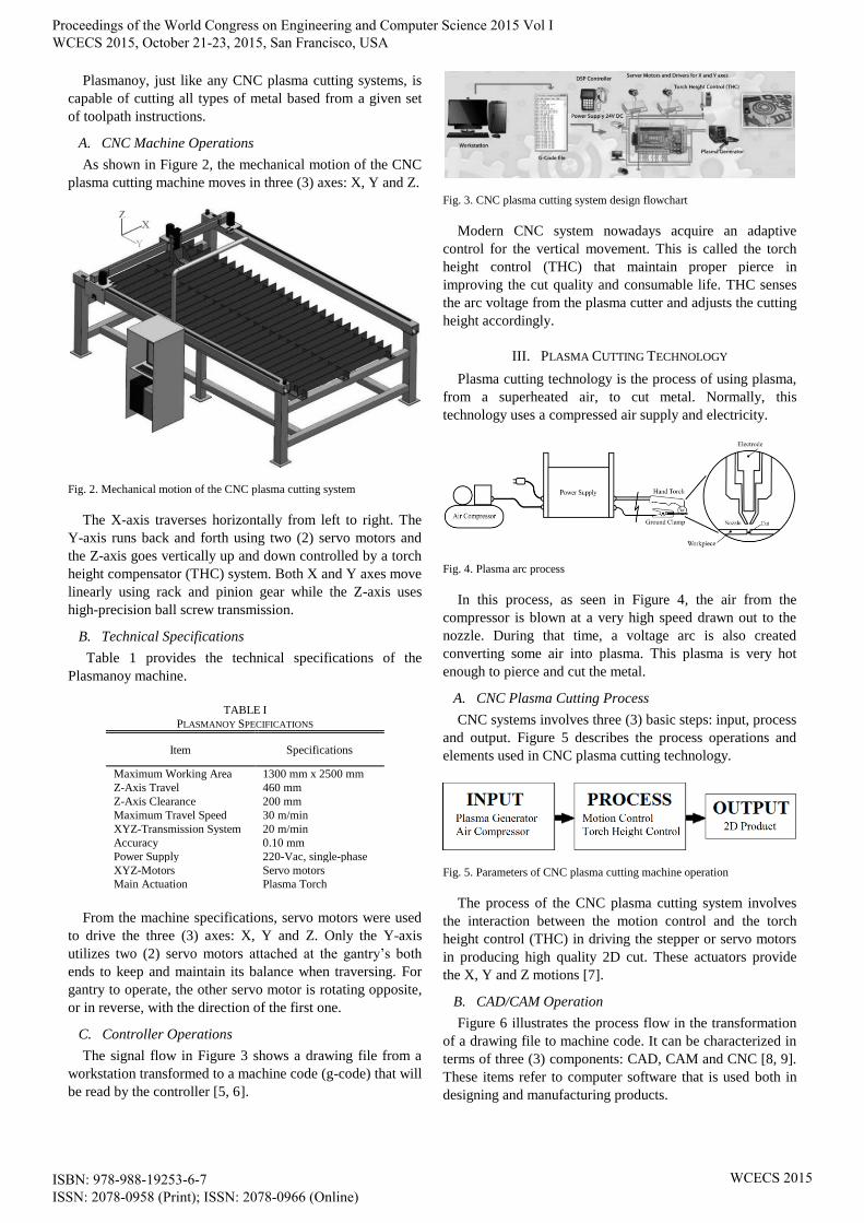
Plasmanoy, just like any CNC plasma cutting systems, is
capable of cutting all types of metal based from a given set
of toolpath instructions.
A. CNC Machine Operations
As shown in Figure 2, the mechanical motion of the CNC
plasma cutting machine moves in three (3) axes: X, Y and Z.
Fig. 2. Mechanical motion of the CNC plasma cutting system
The X-axis traverses horizontally from left to right. The
Y-axis runs back and forth using two (2) servo motors and
the Z-axis goes vertically up and down controlled by a torch
height compensator (THC) system. Both X and Y axes move
linearly using rack and pinion gear while the Z-axis uses
high-precision ball screw transmission.
B. Technical Specifications
Table 1 provides the technical specifications of the
Plasmanoy machine.
TABLE I
PLASMANOY SPECIFICATIONS
Item Specifications
Maximum Working Area 1300 mm x 2500 mm
Z-Axis Travel 460 mm
Z-Axis Clearance 200 mm
Maximum Travel Speed 30 m/min
XYZ-Transmission System 20 m/min
Accuracy 0.10 mm
Power Supply 220-Vac, single-phase
XYZ-Motors Servo motors
Main Actuation Plasma Torch
From the machine specifications, servo motors were used
to drive the three (3) axes: X, Y and Z. Only the Y-axis
utilizes two (2) servo motors attached at the gantry’s both
ends to keep and maintain its balance when traversing. For
gantry to operate, the other servo motor is rotating opposite,
or in reverse, with the direction of the first one.
C. Controller Operations
The signal flow in Figure 3 shows a drawing file from a
workstation transformed to a machine code (g-code) that will
be read by the controller [5, 6].
Fig. 3. CNC plasma cutting system design flowchart
Modern CNC system nowadays acquire an adaptive
control for the vertical movement. This is called the torch
height control (THC) that maintain proper pierce in
improving the cut quality and consumable life. THC senses
the arc voltage from the plasma cutter and adjusts the cutting
height accordingly.
III. PLASMA CUTTING TECHNOLOGY
Plasma cutting technology is the process of using plasma,
from a superheated air, to cut metal. Normally, this
technology uses a compressed air supply and electricity.
Fig. 4. Plasma arc process
In this process, as seen in Figure 4, the air from the
compressor is blown at a very high speed drawn out to the
nozzle. During that time, a voltage arc is also created
converting some air into plasma. This plasma is very hot
enough to pierce and cut the metal.
A. CNC Plasma Cutting Process
CNC systems involves three (3) basic steps: input, process
and output. Figure 5 describes the process operations and
elements used in CNC plasma cutting technology.
Fig. 5. Parameters of CNC plasma cutting machine operation
The process of the CNC plasma cutting system involves
the interaction between the motion control and the torch
height control (THC) in driving the stepper or servo motors
in producing high quality 2D cut. These actuators provide
the X, Y and Z motions [7].
B. CAD/CAM Operation
Figure 6 illustrates the process flow in the transformation
of a drawing file to machine code. It can be characterized in
terms of three (3) components: CAD, CAM and CNC [8, 9].
These items refer to computer software that is used both in
designing and manufacturing products.
Proceedings of the World Congress on Engineering and Computer Science 2015 Vol I WCECS 2015, October 21-23, 2015, San Francisco, USA
ISBN: 978-988-19253-6-7 ISSN: 2078-0958 (Print); ISSN: 2078-0966 (Online)
WCECS 2015

Fig. 6. Signal flow for CNC position control process
The first part is the creation of 2D layout in a computer-
aided drawing (CAD) software. Then, the drawing file will
undergo computer-aided manufacturing (CAM) post-
processing for the generation of the toolpath or the g-codes.
Lastly, the CNC control will be responsible in transforming
these g-codes into X, Y and Z motions [10].
IV. METHODOLOGY
In Figure 7, the controller block diagram of Plasmanoy
where it uses the computing software and the controller to
drive its mechanical system.
Fig. 7. CNC plasma cutting machine block diagram
Figure 8 shows the complete schematic layout of the
motion control board and its pin assignment.
A. Motion Control
Figure 8 shows the actual motion controller board used in
this study. It is used to communicate with the servo drivers
(X and Y) and interact with THC.
Fig. 8. Actual motion controller board used
The schematic diagram in Figure 9 shows the complete
wiring setup starting from the ac power supply, plasma
generator integration through THC and the servo driver
connections.
Fig. 9. CNC motion control board
B. Torch Height Control (THC)
The torch height control (THC) employed in this research,
as seen in Figure 10, is a specialized tool used in any CNC
plasma cutting system.
Fig. 10. Torch height controller (THC) process
This type of control utilizes the arc voltage that it senses
in adjusting the height accordingly. Its main function is to
control the z-height relative to the material being cut. This
height is critical to both cut quality and consumable life.
Employing this controller to any CNC plasma cutting system
ensures good cut quality and helps to minimize some rework
operations.
Proceedings of the World Congress on Engineering and Computer Science 2015 Vol I WCECS 2015, October 21-23, 2015, San Francisco, USA
ISBN: 978-988-19253-6-7 ISSN: 2078-0958 (Print); ISSN: 2078-0966 (Online)
WCECS 2015

V. TESTING
The testing of the controller was performed both in terms
of cutting performance and its capability to read the
generated g-code toolpath from the CAD/CAM software.
Figure 11 shows the drawing template used for testing.
Fig. 11. Drawing template used
This drawing template, generated in VCarve Pro [2],
consists of different patterns and geometric shapes. A total
of 21 points (dimensional and geometric accuracy) were
listed and used to test its performance.
A. Actual Cutting Profile
The actual testing was performed in five (5) trials using a
template to a 2-mm mild steel plate (see Fig. 12).
Fig. 12. Actual profiling using a 2-mm mild steel plate
Fig. 13. Coffee table – a sample plasma cut in stainless steel diagram
Also, a sample test cut using stainless steel plate was
performed to produce high quality and unique metal artwork
products just like the coffee table in Figure 13.
B. Statistical Testing
The controller’s accuracy performance was calculated
using the percentage error (% error) formula, as seen from
Eq. 1, wherein the theoretical is the desired value and the
actual is the measured or observed value.
%100% xltheoretica
ltheoreticaactualerror
(1)
Figure 14 shows the % error of the five (5) trials. Based
from the graph, 0.34% average error was observed which is
significantly good in terms of performance accuracy.
Fig. 14. % error calculation showing 99.66% accuracy (0.34% error)
Also, as depicted from the graph, runs starting from 18 to
21 show high % error values compared with the rest. Figure
15 illustrates the statistical summary of the controller
performance in Minitab. To determine the accuracy and
reliability, standard deviation was also calculated.
Fig. 15. Minitab descriptive statistics
The standard deviation shows the amount of dispersion or
variation. A low standard deviation denotes that the data
tend to be very close to the mean while high standard
deviation means more data points are spread out or
dispersed over a large dataset. Statistical result depicts low
standard deviation.
ACKNOWLEDGMENT
The authors would like to thank the Philippine Council for
Industry, Energy and Emerging Technology Research and
Development (PCIEERD) of the Department of Science and
Technology (DOST) for the research funding, conference
publication support and travel grant.
VI. CONCLUSION
In this study, the controller was able to successfully
demonstrate the capability of the CNC plasma cutting
machine developed in MIRDC. From the results shown in
the VCarve Pro drawing files, the controller was able to read
its generated g-code toolpath format (.tap). For the motion,
four (4) servo motor drivers (2 for Y-axis) were able to
communicate with the motion control board.
Results from the performance test shows that the CNC
machine was able to achieve cutting profiles of up to a 1 mm
Proceedings of the World Congress on Engineering and Computer Science 2015 Vol I WCECS 2015, October 21-23, 2015, San Francisco, USA
ISBN: 978-988-19253-6-7 ISSN: 2078-0958 (Print); ISSN: 2078-0966 (Online)
WCECS 2015

accuracy. Furthermore, a neatly made cut of any metal
profiles and up to a maximum cutting thickness of 25 mm
(for mild steel) were made possible with the help of the
high-capacity 120-ampere plasma generator and the screw-
type air compressor system.
REFERENCES
[1] J. P. Rogelio and R. G. Baldovino, “A PC-based controller for the
computer numerically-controlled (CNC) LASER machine,” 2015
IAENG International Conference on Control and Automation
(ICCA’15), March 16-18, 2015.
[2] VCarve Pro. Retrieved from Vectric: http://www.vectric.com
[3] J. P. Rogelio and R. G. Baldovino, “Development of an automatic
tool changer (ATC) system for the 3-axis computer numerically-
controlled (CNC) router machine,” 7th IEEE International
Conference on Humanoid, Nanotechnology, Information Technology,
Communication and Control, Environment and Management
(HNICEM), November 12-16, 2014.
[4] R. G. Baldovino and J. P. Rogelio, “Optimization of machine process
parameters through 2D image layout enhancing and ArtCAM post-
processing for 3D machining,” 7th IEEE International Conference on
Humanoid, Nanotechnology, Information Technology,
Communication and Control, Environment and Management
(HNICEM), November 12-16, 2014.
[5] R. E. Breaz, G. Racz, O. C. Bologa and V. S. Oleksik, “Motion
control of medium size CNC machine-tools: a hands-on approach,”
7th International Conference on Industrial Electronics and
Applications (ICIEA), pp. 2112-2117, July 18-20, 2012.
[6] R. E. Breaz, O. C. Bologa, C. Biris, G. Racz, C. Girjob and V.
Oleksik, “Method for improving the contouring accuracy for CNC
profiling machines at the shop floor level,” 7th International
Conference on Industrial Informatics (INDIN), pp. 813-818, 2009.
[7] A. Hace and K. Jezernik, “The open CNC controller for a cutting
machine,” IEEE International Conference on Industrial Technology,
vol. 2, pp. 1231-1236, December 10-12, 2003.
[8] P. S. Adler, “CAD/CAM: managerial challenges and research issues,”
IEEE Transactions on Engineering and Management, vol. 36, issue 3,
pp. 202-215, August 1989.
[9] V. Tandon and H. El-Mounayri, “Aspects of integrated CAD/CAM
for advanced manufacturing,” Proceedings of the Electrical Insulation
Conference and Electrical Manufacturing, pp. 539-546, 1999.
[10] P. A. S. da Rocha, R. Diogne de Silva e Souza and M. E. de Lima
Tostes, “Prototype CNC machine design,” 9th IEEE/IAS International
Conference on Industry Applications (INDUSCON), pp. 1-5, 2010.
Proceedings of the World Congress on Engineering and Computer Science 2015 Vol I WCECS 2015, October 21-23, 2015, San Francisco, USA
ISBN: 978-988-19253-6-7 ISSN: 2078-0958 (Print); ISSN: 2078-0966 (Online)
WCECS 2015