Development of a Component Head Injury Criteria (HIC ...Development of a Component Head Injury...
55
DOT/FAA/AR-06/47 Air Traffic Organization Operations Planning Office of Aviation Research and Development Washington, DC 20591 Development of a Component Head Injury Criteria (HIC) Tester for Aircraft Seat Certification— Phase 2 January 2007 Final Report This document is available to the U.S. public through the National Technical Information Service (NTIS), Springfield, Virginia 22161. U.S. Department of Transportation Federal Aviation Administration
Transcript of Development of a Component Head Injury Criteria (HIC ...Development of a Component Head Injury...

DOT/FAA/AR-06/47 Air Traffic Organization Operations Planning Office of Aviation Research and Development Washington, DC 20591
Development of a Component Head Injury Criteria (HIC) Tester for Aircraft Seat Certification—Phase 2 January 2007 Final Report This document is available to the U.S. public through the National Technical Information Service (NTIS), Springfield, Virginia 22161.
U.S. Department of Transportation Federal Aviation Administration

NOTICE
This document is disseminated under the sponsorship of the U.S. Department of Transportation in the interest of information exchange. The United States Government assumes no liability for the contents or use thereof. The United States Government does not endorse products or manufacturers. Trade or manufacturer's names appear herein solely because they are considered essential to the objective of this report. This document does not constitute FAA certification policy. Consult your local FAA aircraft certification office as to its use. This report is available at the Federal Aviation Administration William J. Hughes Technical Center's Full-Text Technical Reports page: actlibrary.tc.faa.gov in Adobe Acrobat portable document format (PDF).
Technical Report Documentation Page 1. Report No. DOT/FAA/AR-06/47
2. Government Accession No. 3. Recipient's Catalog No.
5. Report Date
January 2007
4. Title and Subtitle
DEVELOPMENT OF A COMPONENT HEAD INJURY CRITERIA (HIC) TESTER FOR AIRCRAFT SEAT CERTIFICATION—PHASE 2 6. Performing Organization Code
7. Author(s)
Hamid M. Lankarani 8. Performing Organization Report No.
10. Work Unit No. (TRAIS)
9. Performing Organization Name and Address
National Institute for Aviation Research Wichita State University 1845 N Fairmount Wichita, KS 67260-0093
11. Contract or Grant No.
01-C-AW-WSU Amendment No. 013 13. Type of Report and Period Covered
Final Report 12. Sponsoring Agency Name and Address
U.S. Department of Transportation Federal Aviation Administration Air Traffic Organization Operations Planning Office of Aviation Research and Development Washington, DC 20591
14. Sponsoring Agency Code ANM-100
15. Supplementary Notes
The Federal Aviation Administration Airport and Aircraft Safety R&D Division Program Manager was Gary Frings and the Technical Monitor was Allan Abramowitz. 16. Abstract
The certification of an aircraft interior requires that a head strike to any of the several cabin furnishings comply with the Head Injury Criteria (HIC). This compliance poses a significant problem for many segments of the aerospace industry due to the costs and time required during the development and certification process of 16-g airline seats. The current method of certification requires conducting a full-scale sled test (FSST), which might require the use of a new seat for each dynamic test. It is desirable to use a cheaper, faster, and more repeatable alternative for the certification process. This research addressed the design modification and evaluation of such a device, called the National Institute for Aviation Research Head Injury Component Tester (NHCT). The performance of the NHCT was evaluated for various aircraft interior surfaces to draw a correlation between FSST and NHCT test results. It was shown that the NHCT was capable of producing conservative HIC results. The performance of the NHCT also was evaluated using analytical models that were developed using the Mathematical Dynamic Model biodynamic occupant simulation code. Analytical models demonstrated that the dynamic response of the NHCT was sensitive to the input parameters. The NHCT device aim was to provide an alternate means of compliance with the HIC requirement without consuming a seat or seats during certification testing. Preliminary indications showed that modifying the neck of the NHCT from a rigid design to a flexible design improved the performance. 17. Key Words
Head Injury Criteria (HIC), Component tester, MADYMO, Aircraft seat test, Simulation
18. Distribution Statement
This document is available to the public through the National Technical Information Service (NTIS) Springfield, Virginia 22161.
19. Security Classif. (of this report)
Unclassified
20. Security Classif. (of this page)
Unclassified
21. No. of Pages
55 22. Price
Form DOT F1700.7 (8-72) Reproduction of completed page authorize

ACKNOWLEDGMENTS
The authors gratefully acknowledge the contribution of the staff at the Federal Aviation Administration Civil Aerospace Medical Institute for conducting a series of tests at their facility to evaluate the performance and assist with the setup of the Head Injury Criteria Component Tester Device. Special thanks go to Mr. Van Gowdy, Mr. Richard L. DeWeese, and Mr. David M. Moorcroft.
iii/iv

TABLE OF CONTENTS Page EXECUTIVE SUMMARY xiii 1. INTRODUCTION 1
2. BACKGROUND 1
3. DESCRIPTION OF NHCT 2
4. MODIFICATION OF THE NHCT 5
5. PRELIMINARY EVALUATION OF THE NHCT AT NIAR 7
5.1 Baseline FSSTs Using Aluminum Panels 8 5.2 Comparable NHCT Tests Using Aluminum Panels 9 5.3 Comparison of NHCT Results With FSST Results 11
5.3.1 Evaluation of NHCT Tests 01057-71 and 01057-72 With FSST
96288-16 (Aluminum Panel) 11
5.3.2 Evaluation of NHCT Test 01057-49 Compared With FSST 01008-008 (Nomex Honeycomb Panel) 13
6. MODELING AND ANALYSIS OF NHCT AND FSST USING MADYMO 14
6.1 Setup of the MADYMO Model for the NHCT 14 6.2 MADYMO Model Setup for the FSST 16 6.3 Parametric Study of Impact Surface Stiffness and Setback Distances 19
6.3.1 Parametric Study With FSST 19
6.3.2 Parametric Study With NHCT 21
6.4 Correlation of MADYMO Models for FSST and NHCT 22
6.4.1 Panel Stiffness and HIC at an Impact Angle of 31 Degrees 22 6.4.2 Panel Stiffness and HIC at an Impact Angle of 40 Degrees 23 6.4.3 Panel Stiffness and HIC at an Impact Angle of 53 Degrees 24 6.4.4 Correlation of FSST and NHCT HIC Models 25
7. SUMMARY OF CAMI NHCT TESTS 26
8. EVALUATION OF NHCT TESTS CONDUCTED AT CAMI 28
v

8.1 Raw Test Data 29 8.2 Validated MADYMO NHCT and FSST Models 30
8.2.1 Validation of FSST MADYMO Model 30 8.2.2 Validation of NHCT MADYMO Model 34
8.3 Use of MADYMO NHCT Model to Obtain HIC Values for Input Parameters
Matched to FSSTs 36
8.4 Correlation Between FSST Results and MADYMO NHCT Results 37 9. EVALUATION OF NHCT WITH A FLEXIBLE NECK 38 10. RESULTS 41 11. REFERENCES 42
vi

LIST OF FIGURES
Figure Page 1 Design of NHCT 3
2 Fabricated NHCT 3
3 Design Methodology for the NHCT 4
4 Comparison of Pertinent Parameters for FSST and NHCT 4
5 Computer Block Diagram and Control Screens 5
6 Electronic Pressure Regulator 6
7 Solenoid Supply Valve and Bursting Disc 6
8 Pressure Sensor 7
9 Computer Screen With Posttest Data 7
10 Acceleration Plots for FSST 96288-16 8
11 Velocity Plots for FSST 96288-16 8
12 Data Plots for NHCT Test 01057-72 10
13 Evaluation of Resultant Acceleration for NHCT Tests 01057-71 and 72 With FSST 96288-16 12
14 Repeatability of NHCT Tests 01057-71 and 72 12
15 Comparison of NHCT Test 01057-49 With FSST 01008-8 for Head c.g. Resultant Acceleration 13
16 Process Flow for FSST-NHCT Parametric Study 14
17 Setup of the MADYMO Model for Test 01057-82 15
18 Load Displacement for Panel Used for Test 01057-82 15
19 Head Acceleration Profiles for MADYMO Model and NHCT Test 01057-82 16
20 MADYMO Model Setup for FSST 97191-003 17
21 Load Displacement for Slitted Panel 17
22 Load Displacement for MADYMO Belt Used 17
vii
23 Input Pulse for FSST MADYMO Model 18
24 Head Acceleration Profile for MADYMO Model and FSST 9719-003 18
25 Setup of the MADYMO With ETHAFOAM Panel 19
26 Linear Load Deflection Properties of the ETHAFOAM Panel 19
27 MADYMO Simulation Input Pulse 20
28 MADYMO Lap Belt Load Deflection Properties 20
29 Seat Cushion Load Deflection Properties 20
30 Simulation of the FSST With ETHAFOAM Panel 21
31 Simulation Sequence for Impact Angle of 53 Degrees With ETHAFOAM Panel for the NHCT 22
32 The HIC Correlation for FSST and NHCT MADYMO Models With an Impact Angle of 31 Degrees 23
33 The HIC Correlation for FSST and NHCT MADYMO Models With an Impact Angle of 40 Degrees 24
34 The HIC Correlation for FSST and NHCT MADYMO Models With an Impact Angle of 53 Degrees 24
35 Comparison of MADYMO Models of HIC-FSST vs HIC-NHCT for 31-, 40-, and 53-Degree Impact Angles (Seat Setback of 28, 32, and 37 Inches) 25
36 Different Impact Surfaces Used for CAMI Tests 26
37 Process Flow for Analytical-Experimental Model 28
38 ETHAFOAM Setup for FSST A03007 29
39 Corresponding NHCT Test for FSST A03007 29
40 Finite Element Model of Polyethylene Foam Pad With Duct Tape (Straps) 30
41 MADYMO Model Developed for FSST 31
42 Acceleration Pulse for FSST A03007 31
43 Foam Load Deflection Properties 32
44 Simulation Sequence for Head Strike for FSST A03007 32
viii

45 Simulation Sequence of Foam Deformation and its Relative Motion With Rigid Surface for FSST A03007 33
46 Head Acceleration for FSST and MADYMO Model 33
47 Simulation Sequence for Head Strike NHCT Test H03316 34
48 Simulation Sequence of Foam Deformation and its Relative Motion With Rigid Surface for NHCT Test H03316 35
49 Head Acceleration Profile for Actual Test and Simulation 35
50 Correlation of MADYMO NHCT and FSST 37
51 Head Rotation Angle and Impact Angle 38 52 Head Rotation for Impact Angle of 40 Degrees 38 53 Head Impact for Sled Test and NHCT With Flexible Neck on Polyethylene Pad 39 54 Simulation Sequence for NHCT With Flexible Neck 39 55 Comparison of Head Acceleration Profile for FSST and NHCT Model With Flexible Neck 40 56 Correlation Between FSST and NHCT With Rigid and Flexible Necks 41
ix

LIST OF TABLES
Table Page
1 Test Results of FSST 96288-16 9
2 Test Results of FSSTs 96288-04 to 96288-23 9
3 Test Results of NHCT Tests 01057-55 to 01057-106 10
4 Comparison of NHCT 01057-71 and 72 With FSST 6288-16 12
5 Comparison of NHCT Test 01057-49 With FSST Test 01008-008 (Nomex Honeycomb Panel) 13
6 Comparison of NHCT Test 01057-82 With MADYMO Simulation 16
7 Comparison of FSST 97191-003 With MADYMO Simulation 18
8 The FSST Simulation Results of Panel Stiffness and Impact Angles 21
9 Simulation Results of Panel Stiffness and Impact Angle for the NHCT 22
10 Results of the FSST and NHCT Test Using Different Impact Surfaces 27
11 FSST and NHCT Tests With ETHAFOAM Impact Surface 30
12 Comparison of FSST A03007 With MADYMO Simulation 34
13 Comparison of NHCT Test H03316 With MADYMO Simulation 36
14 Comparison of HIC Results for FSST and NHCT 36
15 Comparison of HIC Results for FSST and MADYMO NHCT 37
16 Comparison of Flexible and Rigid Neck NHCT Model Results and Corresponding FSST Results 40 17 Comparison of FSST Results With Flexible Neck NHCT Model Results 41
x
LIST OF SYMBOLS AND ACRONYMS
ATD Anthropomorphic test dummy c.g. Center of gravity CAMI Civil Aerospace Medical Institute CFR Code of Federal Regulations EPR Electronic pressure regulator FAA Federal Aviation Administration FE Finite element FSST Full-scale sled test HIC Head Injury Criteria MADYMO Mathematical Dynamic Model NHCT National Institute for Aviation Research Head Injury Component Tester NIAR National Institute for Aviation Research
xi/xii

EXECUTIVE SUMMARY Compliance with the Head Injury Criteria (HIC) requirement represents a significant challenge to engineers designing cabin interior furnishings for all classes of aircraft. The Federal Aviation Administration certification of aircraft interiors requires compliance with the HIC requirement as specified in Title 14 Code of Federal Regulations Parts 23.562 and 25.562. Full-scale sled tests (FSST), which are extensively used to evaluate the design of interior furnishings, are destructive tests that might consume several test articles in demonstrating design compliance. HIC compliance poses a significant problem for the airlines and manufacturers due to the costs and time required during the development and certification of 16-g airline seats. These factors have led to the development and potential applicability of a device that will evaluate a design without consuming a seat. The National Institute for Aviation Research (NIAR) Head Injury Criteria Component Tester (NHCT) was designed and fabricated based on a series of FSSTs conducted at NIAR. This device aimed to duplicate full-scale results and operated in a manner that reproduced the forces and accelerations generated in a full-scale test. The NHCT can produce similar inertial system forces that create the same impact velocities and acceleration profiles observed in full-scale tests. Validation of the NHCT was conducted in this study using the biodynamic occupant simulation code Mathematical Dynamic Model (MADYMO) and data from FSSTs. HIC results were compared to FSST results for resultant-head acceleration, HIC, HIC window size, head-impact angle, head-impact velocity, and average head center of gravity acceleration values. Performance of the NHCT was evaluated for various aircraft interior surfaces and compared to results from the FSST. The NHCT produced conservative HIC results compared to the FSSTs. HIC for the HHCT was evaluated for front-row bulkhead seating and row-to-row seating using MADYMO. It was observed that the dynamic response of the NHCT was very sensitive to input parameters. Preliminary indications showed that modifying the neck of the NHCT from a rigid design to a flexible design resulted in decreased differences between the NHCT and FSST results.
xiii/xiv

1. INTRODUCTION.
One of the problems encountered in the certification of 16-g airline seats is what is referred to as the front-row Head Injury Criteria (HIC) problem. This problem occurs for seats located directly behind bulkheads or cabin class dividers. These structures are typically both stiff and strong and tend to produce very high HIC values during head impacts. Another HIC-related issue was encountered in the certification of seats located behind other seats that incorporate devices (such as drop-down tables) and other hard structures (such as video displays). This problem is referred to as the row-to-row HIC problem. Currently, several full-scale sled tests (FSST) are required to determine the HIC values that are produced during head impacts with these bulkheads or front seat structures. Normally, seats used for these tests are destroyed, consequently resulting in significant costs. The objective of this research project is to evaluate a component test apparatus that aims to effectively support the design and certification of aircraft seats to meet HIC requirements. This device will minimize the need for full-scale tests and reduce the associated time and cost for development and certification . 2. BACKGROUND.
Chandler [1] described the development of the HIC that evolved from the Wayne State Tolerance Curve [2]. Gadd [3] defined the severity index based on raising the time integral of head acceleration in g’s to the power of 2.5, after observing this to be the slope of the line that closely fit the Wayne State data when it was plotted using a log-log scale. Gadd also proposed the injury threshold of 1000. Versace [4] subsequently advocated the use of an effective acceleration, which he defined as
{ ∫ dtat5.21
}, where t and a, respectively, represent the time interval and resultant head acceleration. The HIC was subsequently defined by Gurdjian [5 and 6] as
HIC = max
5.2.
.12
122
1
)()(
1)(⎥⎥⎦
⎤
⎢⎢⎣
⎡
⎭⎬⎫
⎩⎨⎧
−− ∫
t
tdtta
tttt
where:
a(t) = resultant acceleration of the head center of gravity (c.g.) in g’s t1 = initial integration time, expressed in seconds t2 = final integration time, expressed in seconds
Maximization is performed by identifying the time interval t2 – t1 that results in the largest functional value. This criterion was adapted from the Federal Motor Vehicle Safety Standard No. 208 [7]. In aerospace applications, the definition differs in that the HIC is evaluated over the period when the head of the anthropomorphic test dummy (ATD) is in contact with any structure on the aircraft interior. Injury is defined as any HIC value exceeding the threshold value of 1000. The HIC subsequently was recommended as one of the injury criteria by the General
1

Aviation Safety Panel to be considered in the design and certification of aircraft seats and restraint systems. HIC requirements were adapted and are specified in Title 14 Code of Federal Regulations (CFR) Parts 23.562 [8] and 25.562 [9]. Alternative methods involving the use of component test devices represent useful engineering tools for HIC evaluation in both the aircraft and the automotive industries. A validated component test device should be simple to use, operate, and control. The device should show good repeatability and produce less data scatter than that obtained from a FSST. Validation of an HIC component tester requires that the measurements of the following parameters from component tests agree with the values of corresponding parameters acquired from FSSTs. • HIC • Average head c.g. resultant acceleration and duration • HIC window, Δt = t2 – t1 • Head c.g. resultant acceleration profile Component testers include the following: • Bowling Ball Tester • Free Motion Headform Tester • MGA Head/Neck Impactor • Pendulum Test Rig Tester A study of these devices determined that they do not provide adequate correlation with the FSSTs for required test conditions [10]. The component-level devices provide reasonable correlation compared with the 16-g dynamic FSSTs only for configurations with predominantly normal head impact velocities, short distances from the impact surface, and relatively short-duration impacts. Factors affecting these differences may include articulation of other body segments for the ATD, belt compliance, translation motion of the pelvis, and friction of the pelvic/seat and head/frontal structure. The National Institute for Aviation Research (NIAR) has developed an HIC component tester designed to overcome the problems facing existing component testers and reproduce the test results of FSSTs of a Hybrid II ATD (49 CFR Part 572). 3. DESCRIPTION OF NHCT.
The National Institute for Aviation Research Head Injury Criteria Component Tester (NHCT) was designed to mimic the kinematics of a 50th percentile male Hybrid II ATD during dynamic testing. The device was intended to produce the same HIC and other kinematics values as a FSST. The following section briefly discusses the design and development of the NHCT. The NHCT device, shown in figures 1 and 2, consists of a Hybrid II ATD head mounted on an aluminum pendulum arm (collectively the upper torso) attached to a translating aluminum mass representing the lower torso. The pendulum arm weighs 7 lb, is 21.2 inches long, and is pinned to the lower torso so that the pendulum can pivot. The mass distribution of the tester is different from the ATD that has variable inertia compared to the ATD due its flailing limbs. This mass
2

distribution was obtained by optimizing the system response for the head acceleration equivalence. The Hybrid II ATD head is connected to the pendulum arm through the neck bracket. Unlike the ATD that has a rubber neck, the NHCT neck is fabricated from rigid polycarbonate. An actuator propels the pendulum through a pivoting support arm and the attached support arm extension. The actuator is mounted on a stand and is supported by bearings on either ends of the trunion. The stand assembly and support arm are bolted in place. The lower torso is attached to two sets of linear bearings that slide on the rails, allowing it to translate forward and aft. This translation represents the ATD snap back in an FSST.
Figure 1. Design of NHCT
Figure 2. Fabricated NHCT
The propulsion system consists of a bottle of pressurized nitrogen gas, an accumulator, a gas valve, tubing, and a control system. Pressurized nitrogen gas is used to charge the accumulator to the required pressure. The accumulator, when triggered by the control system, discharges the nitrogen gas into the actuator, driving the pendulum arm forward. Development of this device as described has followed an iterative approach, which is outlined in figure 3. The methodology included analyzing FSST data, modeling the ATD kinematics through biodynamic simulations, creating a biodynamic model of the tester, conducting a parametric study of the design, designing and fabricating the tester, and finally performing a preliminary evaluation of the tester.
3
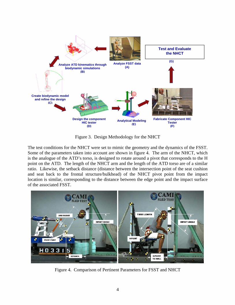
Figure 3. Design Methodology for the NHCT
The test conditions for the NHCT were set to mi ic the geometry and the dynamics of the FSST.
Figure 4. Comparison of Pertinent Parameters for FSST and NHCT
Create biodynamic model and refine the design
(C)
Design the component HIC tester
(D)
Analytical Modeling (E)
Fabricate Component HIC Tester
(F)
Analyze FSST data (A)
Analyze ATD kinematics through biodynamic simulations
(B)
(G)
Test and Evaluate the Component Tester
Test and Evaluate the NHCT
m
Some of the parameters taken into account are shown in figure 4. The arm of the NHCT, which is the analogue of the ATD’s torso, is designed to rotate around a pivot that corresponds to the H point on the ATD. The length of the NHCT arm and the length of the ATD torso are of a similar ratio. Likewise, the setback distance (distance between the intersection point of the seat cushion and seat back to the frontal structure/bulkhead) of the NHCT pivot point from the impact location is similar, corresponding to the distance between the edge point and the impact surface of the associated FSST.
4

4. MODIFICATION OF THE NHCT.
Since HIC values generated by the device are a direct function of the accumulator pressure, lack of repeatability in actuator pressure directly affects the device’s ability to produce repeatable results. The initial design used a manual means to ensure appropriate pretest nitrogen pressure in the accumulator. Safety issues aside, this arrangement also resulted in significant variations in accumulator pressure from test to test. The problems were resolved by placing the device under the control of a computer that, among other functions, was able to control an electronic pressure regulator (EPR). This resulted in repeatable accumulator nitrogen pressures. The interface computer also automated many of the functions that previously had been performed manually. A block diagram of this computer is shown in figure 5.
Figure 5. Computer Block Diagram and Control Screens
As may be noted from the block diagram, the computer can handle most operations required to
uring operation, the desired operating pressure is set, the supply valve is opened, and the accumulator is pressurized to the desired pressure by the interface controller via the EPR shown
operate the device, including opening the gas supply valve, triggering the actuator, and acquiring data. D
5

in figure 6. The regulator is a card-mounted device that does not require gas flow to maintain pressure. This design eliminates the discharge of vented nitrogen while maintaining constant pressure in the accumulator, thus ensuring that no nitrogen is lost during the process. The low, minimum-control volume of 1 in3 ensures a smooth buildup of pressure and allows fine adjustments to be made.
Figure 6. Electronic Pressure Regulato
A silencer was added to the ring the solenoid spool. A bursting disc (figure 7) was included upstream of the solenoid valve to protect the low-pressure
r
EPR primarily to prevent dust from ente
components of the gas supply system from the high-side (gas bottle) pressure of up to 3000 psi.
Bursting Disc
Solenoid Supply Valve
Figure 7. Solenoid Supply Valve and Bursting Disc
The accumulator was rovided the computer with a feedback loop created using the pressure sensor, computer, and the EPR to obtain
instrumented with a pressure sensor (figure 8) that p
repeatable accumulator pressures.
6

Figure 8. Pressure Sensor Once the accumulator is filled to the desired pressure, the system is ready to be activated via the computer. Doing so initiates a 5-second countdown and automatic triggering of the camera and data acquisition system. The system then triggers the solid-state relays, which open the main supply valve from the accumulator to the actuator, thus driving the pendulum arm into the test article. A sensor mounted on the pendulum arm base measures angular position from which the computer calculates both peak velocity and peak time (figure 9).
Figure 9. Computer Screen With Posttest Data
5. PRELIMINARY EVALUATION OF THE NHCT AT NIAR.
A preliminary evaluation of the NHCT was conducted at NIAR [11]. The NHCT had been previously calibrated and evaluated for a setback distance of 35 inches. Although this is the most common seating configuration, other distances related to various cabin class configurations
7

needed to be studied. For this, baseline FSSTs as well as component tests were conducted for other seat setback distances using aluminum and Nomex panels and bulkheads. The tester produced reasonably good performance in replicating the results of the FSSTs for the range of seat setback distances tested, especially for small seat setback angles. 5.1 BASELINE FSSTs USING ALUMINUM PANELS.
A series of 12 FSSTs were conducted using a 0.063-inch-thick aluminum panel (Al 2024-T3) as the bulkhead. The seat setback distance was varied from 28 to 35 in. to obtain head impact angles from 27 to 61 degrees. The details of the tests and the results are discussed below. A polyester lap belt was used for restraining the Hybrid II ATD. A load cell was attached to the lap belt to determine the belt forces. Figures 10 and 11 show the FSST data plots obtained from test 96288-16, the seat setback distance was 33.5 in. The results are listed in table 1.
3.1 3.15 3.2 3.25 3.3 3.35 3.4 3.45 3.5
Time (sec)-20
-15
-10
-5
0
5
10
15
20
Ske
dA
ccel
erat
ion
(g's
)
Sled Acceleration Profile
3.25 3.3 3.35 3.4
Time (sec)-140
-120
-100
-80
-60
-40
-20
0
20
40
60
80
100
120
140H
ead
C.G
.Acc
eler
atio
n(g
's)
X - ComponentY - ComponentZ - ComponentResultant
Head C.G. Acceleration Time History
Figure 10. Acceleration Plots for FSST 96288-16
3.25 3.3 3.35 3.4
Time (sec)0
10
20
30
40
50
60
70
80
90
100
110
120
130
140
Hea
dC
.G.A
ccel
erat
ion
(g's
)
t1=
3.31
91
t2=
3.35
72
HIC = 586
Head C.G.Resultant Acceleration Time History and HIC Calculation
3.25 3.3 3.35 3.4 3.45 3.5 3.55Time (sec)
0
10
20
30
40
50
Hea
dV
eloc
ity(ft
/sec
)
Resultant Head Velocity Time History
Figure 11. Velocity Plots for FSST 96288-16
8

Table 1. Test Results of FSST 96288-16
Parameter FSST 96288-16 Seat setback distance (in.) 33.0 Head impact angle (deg) 44.0 Head impact velocity (ft/sec) 38.9 Sled peak deceleration (g’s) 16.6 HIC 586.0 HIC window (ms) 38.1 Head c.g. resultant peak acceleration (g’s) 129.6 Head c.g. resultant average acceleration (g’s) 47.4
Similarly, results from other FSSTs conducted for different head impact angles are listed in table 2.
Table 2. Test Results of FSSTs 96288-04 to 96288-23
Test No.
Seat Setback Distance
(in.)
Head Impact Velocity (ft/sec)
Head Impact Angle (deg)
Head c.g. Acceleration (g’s) HIC
HIC Window
(sec) 96288-14 35 41.7 61 153.4 47.2 361 23.8 96288-15 34 41.6 51 215.6 180.4 777 1.9 96288-16 33.5 38.9 44 129.6 47.4 586 38.1 96288-17 34.5 42.9 56 113.9 49.6 549 31.9 96288-18 30.6 45.0 38 209.0 64.6 924 27.5 96288-19 28.6 43.6 28 205.4 78.0 1193 22.3 96288-20 29.6 44.4 31 175.3 69.0 906 23.0 96288-22 33.5 52.7 48 143.6 49.5 716 41.8
5.2 COMPARABLE NHCT TESTS USING ALUMINUM PANELS.
Corresponding to the FSSTs, a series of NHCT tests were conducted to evaluate the performance of the NHCT. The NHCT settings were selected to reproduce the FSST impact parameters. The test procedure for the NHCT and data plots for a representative test, 01057-72, are given. NHCT test 01057-72 was conducted using a 0.063-inch-thick aluminum panel (Al 2024-T3) as the bulkhead. This test corresponded with FSST 96288-016. The panel was positioned such that it resulted in a head impact angle of 44 degrees. The accumulator pressure was set to 150 psi to obtain a head impact velocity of 38.9 ft/sec as calculated from the NHCT calibration charts.
Triaxial accelerometers mounted on the Hybrid II ATD head measured the head accelerations in the x, y, and z directions. A high-speed camera was used to record the NHCT’s kinematics. Figure 12 shows the data plots, and table 3 shows the results obtained from the analysis of various tests.
9

1.22 1.23 1.24 1.25 1.26 1.27 1.28 1.29 1.3
Time (sec)-70-60-50-40-30-20-10
0102030405060708090
100110120130
Hea
dC
.G.A
ccel
erat
ion
(g's
)Resultant Accel.X-ComponentY-ComponentZ-Component
Head C.G. Acceleration Time History
1.22 1.23 1.24 1.25 1.26 1.27 1.28 1.29 1.3
Time (sec)0
10
20
30
40
50
60
70
80
90
100
110
120
130
Hea
dC
.G.A
ccel
erat
ion
(g's
)
t1=1
.243
7se
c
t2=1
.280
6se
cHIC=615
Head C.G. Resultant Acceleration Time History and HIC Calculation
1.17 1.18 1.19 1.2 1.21 1.22 1.23 1.24 1.25 1.26 1.27 1.28Time (sec)
0
5
10
15
20
25
30
35
40
45
Res
ulta
ntV
eloc
ity(ft
/sec
)
Resutant Head Velocity (Test# 01057-72)
Figure 12. Data Plots for NHCT Test 01057-72
Table 3. Test Results of NHCT Tests 01057-55 to 01057-106
Test No.
Head Impact
Velocity (ft/sec)
Head Impact Angle
(degree)
HIC Window
(ms) HIC 01057-55 45.0 50 20.0 623 01057-56 46.7 50 36.2 799 01057-57 46.2 53 36.2 766 01057-68 40.0 46 31.9 614 01057-69 40.6 44 35.9 655 01057-70 39.0 43 70.4 620 01057-71 39.5 44 35.2 659 01057-72 40.4 45 36.9 615 01057-73 44.8 59 32.5 183
40.4
45 0
10
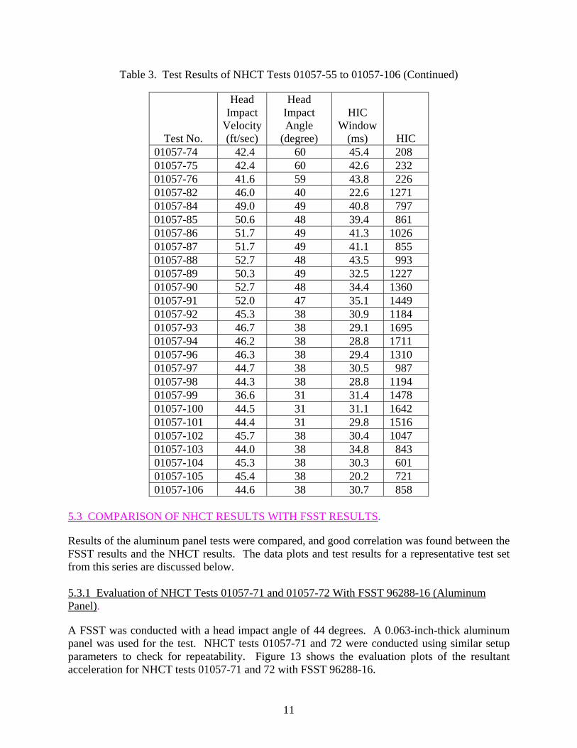
Table 3. Test Results of NHCT Tests 01057-55 to 01057-106 (Continued)
Test No.
Head Impact
Velocity (ft/sec)
Head Impact Angle
(degree)
HIC Window
(ms) HIC 01057-74 42.4 60 45.4 208 01057-75 42.4 60 42.6 232 01057-76 41.6 59 43.8 226 01057-82 46.0 40 22.6 1271 01057-84 49.0 49 40.8 797 01057-85 50.6 48 39.4 861 01057-86 51.7 49 41.3 1026 01057-87 51.7 49 41.1 855 01057-88 52.7 48 43.5 993 01057-89 50.3 49 32.5 1227 01057-90 52.7 48 34.4 1360 01057-91 52.0 47 35.1 1449 01057-92 45.3 38 30.9 1184 01057-93 46.7 38 29.1 1695 01057-94 46.2 38 28.8 1711 01057-96 46.3 38 29.4 1310 01057-97 44.7 38 30.5 987 01057-98 44.3 38 28.8 1194 01057-99 36.6 31 31.4 1478 01057-100 44.5 31 31.1 1642 01057-101 44.4 31 29.8 1516 01057-102 45.7 38 30.4 1047 01057-103 44.0 38 34.8 843 01057-104 45.3 38 30.3 601 01057-105 45.4 38 20.2 721 01057-106 44.6 38 30.7 858
5.3 COMPARISON OF NHCT RESULTS WITH FSST RESULTS.
Results of the aluminum panel tests were compared, and good correlation was found between the FSST results and the NHCT results. The data plots and test results for a representative test set from this series are discussed below. 5.3.1 Evaluation of NHCT Tests 01057-71 and 01057-72 With FSST 96288-16 (Aluminum Panel).
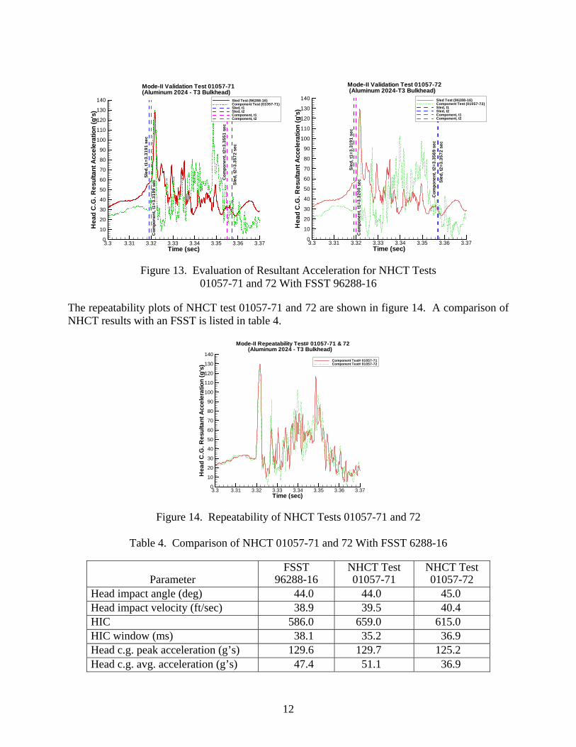
A FSST was conducted with a head impact angle of 44 degrees. A 0.063-inch-thick aluminum panel was used for the test. NHCT tests 01057-71 and 72 were conducted using similar setup parameters to check for repeatability. Figure 13 shows the evaluation plots of the resultant acceleration for NHCT tests 01057-71 and 72 with FSST 96288-16.
11
3.3 3.31 3.32 3.33 3.34 3.35 3.36 3.37Time (sec)
0
10
20
30
40
50
60
70
80
90
100
110
120
130
140H
ead
C.G
.Res
ulta
ntA
ccel
erat
ion
(g's
)Sled Test (96288-16)Component Test (01057-71)Sled, t1Sled, t2Component, t1Component, t2
Mode-II Validation Test 01057-71(Aluminum 2024 - T3 Bulkhead)
Sle
d,t1
=3.3
191
sec
Sle
d,t2
=3.3
572
sec
Com
pone
nt,t
1=3.
3199
sec C
ompo
nent
,t2=
3.35
51se
c
3.3 3.31 3.32 3.33 3.34 3.35 3.36 3.37
Time (sec)0
10
20
30
40
50
60
70
80
90
100
110
120
130
140
Hea
dC
.G.R
esul
tant
Acc
eler
atio
n(g
's)
Sled Test (96288-16)Component Test (01057-72)Sled, t1Sled, t2Component, t1Component, t2
Mode-II Validation Test 01057-72(Aluminum 2024-T3 Bulkhead)
Sle
d,t1
=3.3
191
sec
Sle
d,t2
=3.3
572
sec
Com
pone
nt,t
1=3.
3200
sec
Com
pone
nt,t
2=3.
3569
sec
Figure 13. Evaluation of Resultant Acceleration for NHCT Tests 01057-71 and 72 With FSST 96288-16
The repeatability plots of NHCT test 01057-71 and 72 are shown in figure 14. A comparison of NHCT results with an FSST is listed in table 4.
3.3 3.31 3.32 3.33 3.34 3.35 3.36 3.37Time (sec)
0
10
20
30
40
50
60
70
80
90
100
110
120
130
140
Hea
dC
.G.R
esul
tant
Acc
eler
atio
n(g
's)
Component Test# 01057-71Component Test# 01057-72
Mode-II Repeatability Test# 01057-71 & 72(Aluminum 2024 - T3 Bulkhead)
Figure 14. Repeatability of NHCT Tests 01057-71 and 72
Table 4. Comparison of NHCT 01057-71 and 72 With FSST 6288-16
Parameter FSST
96288-16 NHCT Test 01057-71
NHCT Test 01057-72
Head impact angle (deg) 44.0 44.0 45.0 Head impact velocity (ft/sec) 38.9 39.5 40.4 HIC 586.0 659.0 615.0 HIC window (ms) 38.1 35.2 36.9 Head c.g. peak acceleration (g’s) 129.6 129.7 125.2 Head c.g. avg. acceleration (g’s) 47.4 51.1 36.9
12

From the above data plots and the results, it was found that the NHCT results correlated well with the FSST results for peak and duration of the initial contact and had good repeatability. 5.3.2 Evaluation of NHCT Test 01057-49 Compared With FSST 01008-008 (Nomex Honeycomb Panel).
An NHCT test was conducted to compare the data obtained with that from FSST 01008-008. Results are listed in table 5. Figure 15 shows the comparison plots of the head c.g. resultant acceleration profiles of NHCT test 01057-49 and FSST 01008-008.
Table 5. Comparison of NHCT Test 01057-49 With FSST Test 01008-008 (Nomex Honeycomb Panel)
Description FSST Test 01008-008
NHCT Test 01057-49
HIC 862 800 Head impact angle (deg) 40.0 38.7 Head-impact velocity (ft/sec) 44.5 41.2 HIC window (ms) 28.7 12.1 Head c.g. peak acceleration (g’s) 132.3 109.0 Head c.g. avg. acceleration (g’s) 61 73
3.19 3.2 3.21 3.22 3.23Time (sec)
10
20
30
40
50
60
70
80
90
100
110
120
130
Res
ulta
ntH
ead
CG
Acc
eler
atio
n(g
's)
Sled Test DataComponent Test DataT1=3.2087T2=3.2385
Comparison of Head CG Resultant Acceleration Data betweenComponent Test# 01057-49 and Sled Test#01008-008
T1=3
.208
7
T2=3
.238
5
Figure 15. Comparison of NHCT Test 01057-49 With FSST 01008-8 for Head c.g. Resultant Acceleration
Preliminary panel evaluation tests conducted at NIAR indicated that the NHCT generally provided values that underpredict HIC compared to the FSST by as much as 15 to 17 percent.
13

6. MODELING AND ANALYSIS OF NHCT AND FSST USING MADYMO.
A series of analytical models were built using the biodynamic occupant simulation code Mathematical Dynamic Model (MADYMO) to study the influence of various test parameters and their effects on the FSST and NHCT test results. These models were validated against appropriate FSST and NHCT tests. A flow chart depicting this process is provided in figure 16.
Figure 16. Process Flow for FSST-NHCT Parametric Study
6.1 SETUP OF THE MADYMO MODEL FOR THE NHCT.
The NHCT MADYMO model was built from three bodies: a slider joined to the reference space via a translational joint, a pendulum arm connected to the slider through a revolute joint, and a neckpiece connected to the head with rigid joints. The head used was identical to that of a 50th percentile male Hybrid II ATD.
14
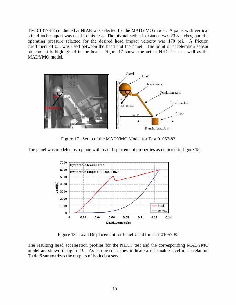
Test 01057-82 conducted at NIAR was selected for the MADYMO model. A panel with vertical slits 4 inches apart was used in this test. The pivotal setback distance was 23.5 inches, and the operating pressure selected for the desired head impact velocity was 170 psi. A friction coefficient of 0.3 was used between the head and the panel. The point of acceleration sensor attachment is highlighted in the head. Figure 17 shows the actual NHCT test as well as the MADYMO model.
Figure 17. Setup of the MADYMO Model for Test 01057-82 The panel was modeled as a plane with load displacement properties as depicted in figure 18.
0
1000
2000
3000
4000
5000
6000
7000
0 0.02 0.04 0.06 0.08 0.1 0.12 0.14Displacement(m)
Load
(N)
loadunload
Hysteresis Model ="1"
Hysteresis Slope = "1.0000E+07"
Figure 18. Load Displacement for Panel Used for Test 01057-82 The resulting head acceleration profiles for the NHCT test and the corresponding MADYMO model are shown in figure 19. As can be seen, they indicate a reasonable level of correlation. Table 6 summarizes the outputs of both data sets.
15

0
20
40
60
80
100
120
140
1.78 1.8 1.82 1.84 1.86 1.88 1.9
Time (sec)
Hea
d C
.G R
esul
tant
Acc
eler
atio
n (g
)
Component HICtest#01057-82Comp.HIC-Madymo5.4 Simulation
Figure 19. Head Acceleration Profiles for MADYMO Model and NHCT Test 01057-82
Table 6. Comparison of NHCT Test 01057-82 With MADYMO Simulation
Parameters NHCT Test 01057-82 MADYMO Simulation
Head impact angle (deg) 40.0 40.0 Head impact velocity (ft/sec) 46.0 46.1 HIC 1271.0 1222.0 HIC window (ms) 22.6 22.6 Head c.g. peak acceleration (g’s) 110.0 117.0 Head c.g. avg. acceleration (g’s) 79.3 90.1
Other NHCT tests were also compared with the MADYMO model. The model again indicated a reasonable level of correlation. A similar set of comparative tests is described in section 8.2.2. 6.2 MADYMO MODEL SETUP FOR THE FSST.
A MADYMO model was developed for several FSSTs. As a representation, the model developed for FSST 97191-003 is shown in figure 20. The seat setback distance was 34 inches and the identical Nomex honeycomb panel, with vertical slits 4 inches apart, was used in the FSST. The same properties were used in the MADYMO models as used in the NHCT test. The head impact angle and velocity obtained from the sled test were 40 degrees and 46 ft/sec respectively. The seat was developed using planes in the reference space along with the panel. A Hybrid II ATD was positioned on the seat with the desired orientation. The friction used between the ATD, seat, and panel was 0.3. The loading and unloading curves for the panels are shown in figure 21.
16

Figure 20. MADYMO Model Setup for FSST 97191-003
0
1000
2000
3000
4000
5000
6000
7000
0 0.02 0.04 0.06 0.08 0.1 0.12 0.14Displacement(m)
Load
(N)
loadunload
Hysteresis Model ="1"
Hysteresis Slope = "1.0000E+07"
Figure 21. Load Displacement for Slitted Panel The MADYMO model required the use of a lap belt. The properties of the MADYMO belt used for this purpose are shown in figure 22. The hysteresis is produced following portions of the loading and unloading curve as defined in MADYMO [12]. The input pulse for the MADYMO model is shown in figure 23.
0
100
200
300
400
500
600
0 0.01 0.02 0.03 0.04 0.05
Displacement (m)
Forc
e (N
)
loadunload
Hysteresis slope= 1.00000E+06
Hysteresis model = "1"
Figure 22. Load Displacement for MADYMO Belt Used
17

0
20
40
60
80
100
120
140
160
180
0 0.05 0.1 0.15 0.2
Time (sec)
Acc
eler
atio
n(m
/sec
^2)
Figure 23. Input Pulse for FSST MADYMO Model The head acceleration profiles for both the FSST as well as the MADYMO model were compared in figure 24 and observed to match quite closely. The outputs from both sets of data are listed in table 7 and indicate that the MADYMO model can be used to evaluate the FSST with a reasonable level of confidence. This MADYMO model has also been used in another set of comparative tests in section 8.2.1.
0
20
40
60
80
100
120
0 0.1 0.2 0.3 0.4 Time (sec)
Hea
d c.
g. R
esul
tant
A
ccel
erat
ion
(g)
MADYMOFSST 9719-003
Figure 24. Head Acceleration Profile for MADYMO Model and FSST 9719-003
Table 7. Comparison of FSST 97191-003 With MADYMO Simulation
Parameters FSST 97191-003 MADYMO Simulation Head impact angle (deg) 40.0 40.0 Head impact velocity (ft/sec) 46.0 46.1 HIC 1131.0 1220.0 HIC window (ms) 22.6 22.6 Head c.g. peak acceleration (g’s) 113.2 99.3 Head c.g. avg. acceleration (g’s) 76.1 67.6
18

6.3 PARAMETRIC STUDY OF IMPACT SURFACE STIFFNESS AND SETBACK DISTANCES.
Using the two previous FSST and NHCT MADYMO models, a parametric study of both systems was conducted with the intent of understanding the dynamic response of NHCT for different scenarios, and to develop a correlation model between the FSST and NHCT. The results show that for a given setback distance, HIC increases with an increase in stiffness of the impact surface panel. 6.3.1 Parametric Study With FSST.
This section describes a parametric study conducted using the MADYMO model derived from sled tests using ETHAFOAM™ panels. This study was conducted with the intent of understanding the effect of panel stiffness and impact angle on the dynamic behavior of NHCT. The setup of the MADYMO model is shown in figure 25. A model with a range of assumed linear values was used to represent stiffness properties (linear force deflection properties) of the impact surface. Figure 26 shows the load-deflection properties of the panel.
Figure 25. Setup of the MADYMO With ETHAFOAM Panel
0 2000 4000 6000 8000
10000 12000 14000 16000
0 0.02 0.04 0.06 0.08 0.1 0.12 0.14 Displacement (m)
Forc
e (N
)
load
Hysteresis Model ='None'
Figure 26. Linear Load Deflection Properties of the ETHAFOAM Panel
19
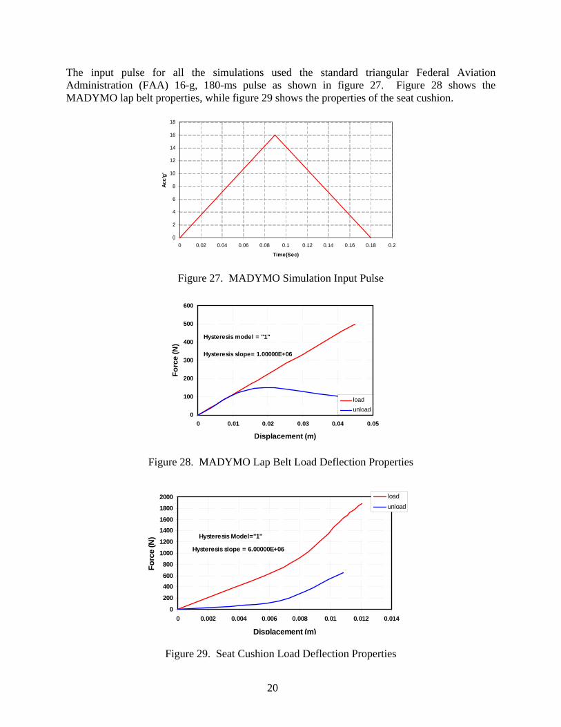
The input pulse for all the simulations used the standard triangular Federal Aviation Administration (FAA) 16-g, 180-ms pulse as shown in figure 27. Figure 28 shows the MADYMO lap belt properties, while figure 29 shows the properties of the seat cushion.
0
2
4
6
8
10
12
14
16
18
0 0.02 0.04 0.06 0.08 0.1 0.12 0.14 0.16 0.18 0.2
Time(Sec)
Acc'
g'
Figure 27. MADYMO Simulation Input Pulse
0
100
200
300
400
500
600
0 0.01 0.02 0.03 0.04 0.05
Displacement (m)
Forc
e (N
)
loadunload
Hysteresis slope= 1.00000E+06
Hysteresis model = "1"
Figure 28. MADYMO Lap Belt Load Deflection Properties
p
0
200
400600
800
1000
1200
14001600
1800
2000
0 0.002 0.004 0.006 0.008 0.01 0.012 0.014
Displacement (m)
Forc
e (N
)
loadunload
Hysteresis Model="1"
Hysteresis slope = 6.00000E+06
Figure 29. Seat Cushion Load Deflection Properties
20

Figure 30 shows the MADYMO model simulation sequence. The results of the parametric study are shown in table 8.
1
Figure 30. Simulation of the FSST With ETHAFOAM Panel
Table 8. The FSST Simulation Results of Panel Stiffness and Impact Angles
Stiffness (lb/in.) Impact Angle 50 100 150 200 300 400 500 600
HIC 31 (deg) HIC window
210 [Δt=15ms]
435 [Δt=15ms]
721 [Δt=9ms]
968 [Δt=10ms]
1619 [Δt=11ms]
2111 [Δt=9ms]
2616 [Δt=8ms]
3114 [Δt=15ms]
HIC 40 (deg) HIC window
160 [Δt=15ms]
340 [Δt=15ms]
670 [Δt=11ms]
1044 [Δt=13ms]
1491 [Δt=11ms]
1931 [Δt=11ms]
2377 [Δt=9ms]
2771 [Δt=8ms]
HIC 53 (deg) HIC window
120 [Δt=15ms]
228 [Δt=15ms]
387 [Δt=15ms]
503 [Δt=15ms]
721 [Δt=13ms]
916 [Δt=13ms]
1112 [Δt=11ms]
1293 [Δt=9ms]
6.3.2 Parametric Study With NHCT.
As was the case for the FSST, a parametric study was carried out for the NHCT MADYMO model. The NHCT model was validated using NHCT test 01057-82. The panel was given the same load deflection curve as that used in the simulation of previous sled tests. The simulation sequence is shown in figure 31. A series of simulations was conducted with similar panel properties and head impact angles as used for the previous sled test to study the effect of these factors on the HIC value. Moving the panel closer to or away from the tester changed the impact angle. The data from these tests are listed in table 9.
3 2
4 6 5
21

1 3 2
4 6 5
Figure 31. Simulation Sequence for Impact Angle of 53 Degrees With ETHAFOAM Panel for the NHCT
Table 9. Simulation Results of Panel Stiffness and Impact Angle for the NHCT
Stiffness (lb/in) Impact Angle 50 100 150 200 300 400 500 600
HIC 31 (deg) HIC window
283 [Δt=15ms]
714 [Δt=15ms]
1040 [Δt=13ms]
1280 [Δt=11ms]
1771 [Δt=15ms]
2181 [Δt=8ms]
2774 [Δt=6ms]
3154 [Δt=6ms]
HIC 40 (deg) HIC window
159 [Δt=15ms]
525 [Δt=15ms]
850 [Δt=15ms]
1152 [Δt=13ms]
1589 [Δt=10ms]
2020 [Δt=15ms]
2390 [Δt=7.0ms]
2733 [Δt=7.0ms]
HIC 53 (deg) HIC window
48 [Δt=15ms]
164 [Δt=15ms]
347 [Δt=15ms]
536 [Δt=15ms]
884 [Δt=15ms]
1191 [Δt=13ms]
1488 [Δt=11ms]
1776 [Δt=10ms]
From the results of the parametric studies listed in tables 8 and 9, the HIC is inversely proportional to the impact angle. This correlation is depicted in the following section.
6.4 CORRELATION OF MADYMO MODELS FOR FSST AND NHCT.
Correlation for impact angles of 31, 40, and 53 degrees was performed for the NHCT and FSST MADYMO models.
6.4.1 Panel Stiffness and HIC at an Impact Angle of 31 Degrees.
Figure 32 shows the relationship between the panel stiffness and HIC value for the NHCT and the FSST at an impact angle of 31 degrees. The HIC values for the NHCT and the FSST were calculated using the coefficients derived in MADYMO (equations 1 and 2).
HICNHCT = 5.54 K (1) HICFSST = 5.22 K (2)
where: K = Stiffness of the panel (lb/in.)
22

y = 5.5408xR2 = 0.9801
y = 5.2237xR2 = 0.9954
0
500
1000
1500
2000
2500
3000
3500
0 100 200 300 400 500 600 700
Stiffness(lb/in)
HIC
NHCTFSST
Figure 32. The HIC Correlation for FSST and NHCT MADYMO ModelsWith an Impact Angle of 31 Degrees
The equations obtained can be used to predict the HIC relationship between the NHCT and the FSST (equation 3).
06.1=FSST
NHCT
HICHIC
(3)
This relationship applies when the head impact angle is 31 degrees and corresponding pivotal setback distance for the NHCT is 18 in. (seat setback distance of 28 in.). 6.4.2 Panel Stiffness and HIC at an Impact Angle of 40 Degrees.
Figure 33 shows the relationship between the panel stiffness and HIC value for the NHCT and the FSST at an impact angle of 40 degrees. The HIC values for the NHCT and the FSST were calculated using the coefficients derived in MADYMO (equations 4 and 5). HICNHCT = 4.84 K (4) HICFSST = 4.72 K (5) where: K = Stiffness of the panel (lb/in.) The equations obtained can be used to predict the HIC relationship between the NHCT and the FSST (equation 6).
02.1=FSST
NHCT
HICHIC
(6)
This relationship applies when the head impact angle is 40 degrees and corresponding pivotal setback distance for the NHCT is 22.5 in. (seat setback distance of 32 in.).
23

Figure 33. The HIC Correlation for FSST and NHCT MADYMO Models With an Impact Angle of 40 Degrees
y = 4.8541xR2 = 0.9806
y = 4.7295xR2 = 0.9928
0
500
1000
1500
2000
2500
3000
3500
0 100 200 300 400 500 600 700
Stiffness(lb/in)
HIC
NHCTFSST
6.4.3 Panel Stiffness and HIC at an Impact Angle of 53 Degrees.
Figure 34 shows the relationship between the panel stiffness and HIC value for the NHCT and the FSST at an impact angle of 53 degrees. The HIC values for the NHCT and the FSST were calculated using the coefficients derived in MADYMO (equations 7 and 8). HICNHCT = 2.91 K (7) HICFSST = 2.24 K (8) where: K = Stiffness of the panel (lb/in.)
y = 2.919xR2 = 0.9864
y = 2.2488xR2 = 0.9911
0200400600800
100012001400160018002000
0 100 200 300 400 500 600 700
Stiffness(lb/in)
HIC
NHCTFSST
Figure 34. The HIC Correlation for FSST and NHCT MADYMO Models With an Impact
Angle of 53 Degrees
24
The equations obtained can be used to predict the HIC relationship between the NHCT and the FSST (equation 9).
29.1=FSST
NHCT
HICHIC
(9)
This relationship can be used when the head impact angle is 53 degrees and the corresponding pivotal setback distance for the tester is 27.5 in. (seat setback distance of 37 in.). 6.4.4 Correlation of FSST and NHCT HIC Models.
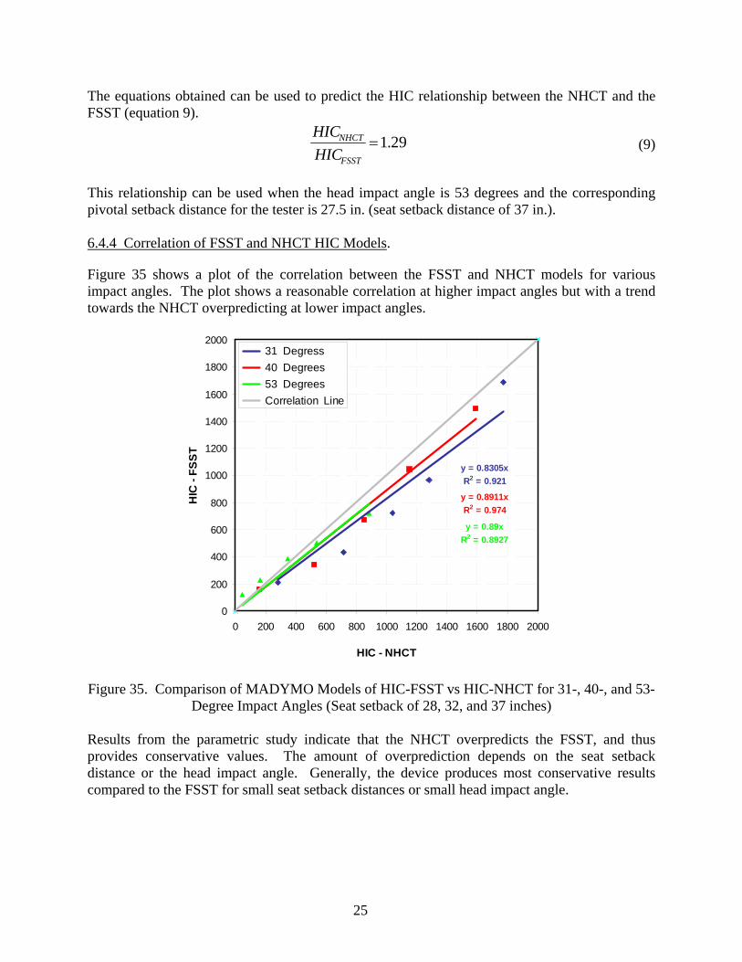
Figure 35 shows a plot of the correlation between the FSST and NHCT models for various impact angles. The plot shows a reasonable correlation at higher impact angles but with a trend towards the NHCT overpredicting at lower impact angles.
y = 0.8305xR2 = 0.921
Figure 35. Comparison of MADYMO Models of HIC-FSST vs HIC-NHCT for 31-, 40-, and 53-
Degree Impact Angles (Seat setback of 28, 32, and 37 inches) Results from the parametric study indicate that the NHCT overpredicts the FSST, and thus provides conservative values. The amount of overprediction depends on the seat setback distance or the head impact angle. Generally, the device produces most conservative results compared to the FSST for small seat setback distances or small head impact angle.
y = 0.8911xR2 = 0.974
y = 0.89xR2 = 0.8927
0
200
400
600
800
1000
1200
1400
1600
1800
2000
0 200 400 600 800 1000 1200 1400 1600 1800 2000
HIC - NHCT
HIC
- FS
ST
31 Degress 40 Degrees 53 Degrees Correlation Line
25
7. SUMMARY OF CAMI NHCT TESTS.
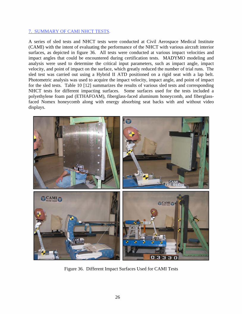
A series of sled tests and NHCT tests were conducted at Civil Aerospace Medical Institute (CAMI) with the intent of evaluating the performance of the NHCT with various aircraft interior surfaces, as depicted in figure 36. All tests were conducted at various impact velocities and impact angles that could be encountered during certification tests. MADYMO modeling and analysis were used to determine the critical input parameters, such as impact angle, impact velocity, and point of impact on the surface, which greatly reduced the number of trial runs. The sled test was carried out using a Hybrid II ATD positioned on a rigid seat with a lap belt. Photometric analysis was used to acquire the impact velocity, impact angle, and point of impact for the sled tests. Table 10 [12] summarizes the results of various sled tests and corresponding NHCT tests for different impacting surfaces. Some surfaces used for the tests included a polyethylene foam pad (ETHAFOAM), fiberglass-faced aluminum honeycomb, and fiberglass-faced Nomex honeycomb along with energy absorbing seat backs with and without video displays.
Figure 36. Different Impact Surfaces Used for CAMI Tests
26

Table 10. Results of the FSST and NHCT Test Using Different Impact Surfaces
Surface Test ID Head Velocity
(ft/sec) Impact Angle
(degree) HIC HIC Duration
(ms) A03007 32.2 45.7 304 28 A03008 32.6 46.7 302 29 H03316 28.3 43.0 400 19 A03011 38.7 40.6 667 17 A03013 38.7 40.6 699 21 H03314 36.9 43.0 756 18 A03009 42.4 41.6 1047 16 A03010 43.8 42.9 1044 16 H03315 40.3 43.0 918 23 H03317 39.5 43.0 942 15 H03318 39.0 43.0 873 17
Polyethylene foam pad (ETHAFOAM)
H03319 39.3 43.0 923 17 A03022 42.1 42.4 772 20 H03322 41.9 42.4 726 26 A03023 46.3 38.4 1009 21
Fiberglass-faced, aluminum honeycomb
H03329 45.8 37.9 802 26 A03015 38.0 44.6 1110 17 A03018 37.9 44.1 944 16
Narrow, fiberglass-faced Nomex honeycomb panel
H03325 37.7 44.9 389 5 A03004 44.7 53.2 1084 7 Wide, fiberglass-faced,
Nomex honeycomb panel H03320 47.6 53.0 1420 23 A03028 41.6 43.8 458 34 Narrow-body class divider
panel H03330 41.6 44.0 285 36 A03027 40.5 45.8 1547 5 A03034 41.3 49.5 1597 11
Wide-body class divider panel
H03331 40.8 44.0 670 9 SEAT BACK TESTS
Seatback centered A04075 47.4 38.5 1207 29 A04076 48.0 38.7 1179 25 A04077 47.4 38.9 1225 10 H04304 51.5 40.0 819 12 H04305 51.6 40.0 804 12 H04306 50.5 40.0 818 12 Seatback offset A04081 49.2 41.4 867 7 A04082 48.1 42.9 907 7 A04083 48.8 42.8 801 11 H04307 51.0 42.6 737 17 H04308 50.0 42.6 881 19 H04309 49.2 42.6 674 7 Note: FSST ID numbers start with A. NHCT ID numbers start with H.
27

8. EVALUATION OF NHCT TESTS CONDUCTED AT CAMI.
It is generally known that HIC is quite sensitive to input parameters such as head impact angle, head impact velocity, and impact location. MADYMO models have shown that minor changes in the input parameters, such as impact angle and velocity, can result in noticeable variations in the resulting HIC values. The FSST and NHCT tests conducted at CAMI (table 10) were originally intended to be used on a one-to-one basis to evaluate the correlation of the resulting HIC values from the two systems. However, some level of difficulty was encountered in matching the input parameters for both systems, i.e., the tests were not carried out under identical conditions. This resulted in most of the FSST parameters having some degree of variation from their corresponding NHCT tests that would possibly contribute a sizable degree of uncertainty to any one-to-one comparison carried out as originally envisaged. In view of this, it became necessary to devise a methodology that would make it possible to obtain sets of data that could be compared on a one-to-one basis. This was done using a analytical-experimental modeling process, as outlined in figure 37 and detailed below. This study also gave an indication of the substantial variations in HIC caused by minor variations in test conditions.
Raw
Tes
tD
ata
Val
idat
edM
ADYM
OM
odel
Val
idat
ed Im
pact
Targ
et M
odel
MAD
YM
O N
HC
TM
odel
Use
d to
Obt
ain
HIC
Val
ues
for I
nput
Para
met
ers
Mat
ched
to F
SS
T
Cor
rela
tion
Betw
een
FSS
T an
dN
HC
TO
btai
ned
Sec
tion
8.1
Sect
ion
8.2
Sect
ion
8.4
Sect
ion
8.5
Figure 37. Process Flow for Analytical-Experimental Model
28

8.1 RAW TEST DATA.
The raw data used for this process was obtained from the test results from table 10. The impact surface used was ETHAFOAM, which represented the heavily padded interior surface of an aircraft structure. The ETHAFOAM used was 4 inches thick and possessed a smooth surface, as shown in figure 38. The corresponding NHCT test, which was conducted to match the FSST, is shown in figure 39.
Figure 38. ETHAFOAM Setup for FSST A03007
Figure 39. Corresponding NHCT Test for FSST A03007
The corresponding input parameters are shown in table 11. As noted, some variation in the input parameters occurs.
29

Table 11. FSST and NHCT Tests With ETHAFOAM Impact Surface
Test ID Head Velocity (ft/sec)
Impact Angle (degree) HIC HIC Duration
(ms) A03007 32.2 45.7 304 28 H03316 28.3 43.0 400 19
Note: FSST ID numbers start with A. NHCT ID numbers start with H. 8.2 VALIDATED MADYMO NHCT AND FSST MODELS.
Separate MADYMO models were developed for both the NHCT and FSST using identical ETHAFOAM targets secured to a rigid surface using duct tape as detailed in the next section. 8.2.1 Validation of FSST MADYMO Model.
The tests were simulated using a MADYMO 50th percentile Hybrid II ATD. The finite element (FE) model of polyethylene foam pad was modeled using solid elements. The duct tape holding the foam with the rigid support was modeled as straps (Kelvin elements) with a stiffness of
N/m, to hold the FE foam on the rigid FE surface, as shown in figure 40. A MADYMO seat belt was used to restrain the ATD. The seat back and pan were simulated using planes, while the cushion itself was represented by a 1-inch-thick ellipsoid with the same properties as used at CAMI. The setup is shown in figure 41. The simulation was carried out to validate the MADYMO model for test A03007.
6102×
Figure 40. Finite Element Model of Polyethylene Foam Pad With Duct Tape (Straps)
30
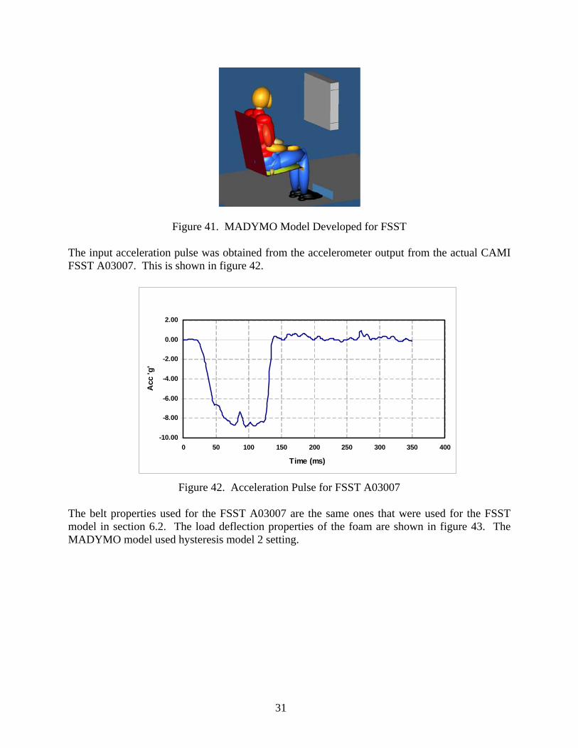
Figure 41. MADYMO Model Developed for FSST The input acceleration pulse was obtained from the accelerometer output from the actual CAMI FSST A03007. This is shown in figure 42.
-10.00
-8.00
-6.00
-4.00
-2.00
0.00
2.00
0 50 100 150 200 250 300 350 400
Time (ms)
Acc
'g'
Figure 42. Acceleration Pulse for FSST A03007 The belt properties used for the FSST A03007 are the same ones that were used for the FSST model in section 6.2. The load deflection properties of the foam are shown in figure 43. The MADYMO model used hysteresis model 2 setting.
31

-6000
-5000
-4000
-3000
-2000
-1000
0
1000
-2.5 -2 -1.5 -1 -0.5 0 0.5
Deflection (m)
Load
(KN
)
LoadUnload
Figure 43. Foam Load Deflection Properties A sequence of the resulting simulation of the MADYMO model is shown in figure 44.
1 3 2
4 6 5
Figure 44. Simulation Sequence for Head Strike for FSST A03007
The ensuing deformation and slip of the MADYMO model of the ETHAFOAM target is shown in figure 45. This response is very close to that observed during actual head impact in FSST.
32
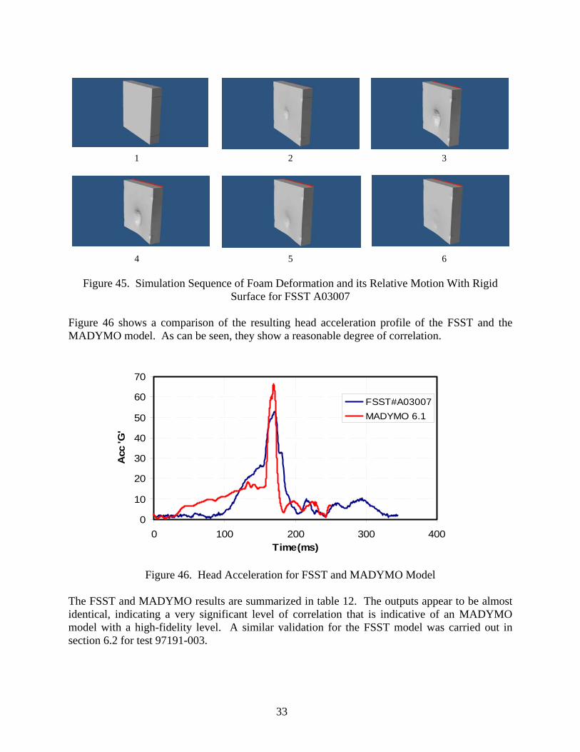
Figure 45. Simulation Sequence of Foam Deformation and its Relative Motion With Rigid
Surface for FSST A03007 Figure 46 shows a comparison of the resulting head acceleration profile of the FSST and the MADYMO model. As can be seen, they show a reasonable degree of correlation.
Figure 46. Head Acceleration for FSST and MADYMO Model
The FSST and MADYMO results are summarized in table 12. The outputs appear to be almost identical, indicating a very significant level of correlation that is indicative of an MADYMO model with a high-fidelity level. A similar validation for the FSST model was carried out in section 6.2 for test 97191-003.
0
10
20
30
40
50
60
70
0 100 200 300 400Time(ms)
Acc
'G'
FSST#A03007MADYMO 6.1
1 3 2
4 6 5
33

Table 12. Comparison of FSST A03007 With MADYMO Simulation
Parameters FSST A03007 MADYMO Simulation Head impact angle (deg) 45.7 45.5 Head impact velocity (ft/sec) 32.2 32.1 HIC 304.0 315.0 HIC window (ms) 28.0 28.0 Head c.g. peak acceleration (g’s) 52.0 65.0 Head c.g. avg. acceleration (g’s) 33.0 28.0
8.2.2 Validation of NHCT MADYMO Model.
The NHCT MADYMO model used the same input parameters and impact target as NHCT test H03316. The resulting simulation sequence and target dynamics are shown in figures 47 and 48.
1 2 3
4
Figure 47. Simulation Sequence for Head Strike NHCT Test H03316
6 5
34

1
Figure 48. Simulation Sequence of Foam Deformation and its Relative Motion With Rigid
Surface for NHCT Test H03316 Figure 49 shows a comparison of the resulting head acceleration profile of the NHCT and the corresponding MADYMO model, which are similar. The resulting output parameters are tabulated in table 13. A very significant correlation of the outputs and hence conformation of a high-fidelity model can be noted. A similar validation sequence for this model was carried out in section 6.1 for NHCT test 01057-82.
0
10
20
30
40
50
60
70
80
-100 -50 0 50 100 150 200Time (msec)
Acc
('g')
H03316-43DEGMADYMO-43DEG
Figure 49. Head Acceleration Profile for Actual Test and Simulation
3 2
4 5 6
35

Table 13. Comparison of NHCT Test H03316 With MADYMO Simulation
Parameters NHCT Test H03316
43 degree MADYMO Simulation
Head impact angle (deg) 43.0 43.0 Head impact velocity (ft/sec) 28.3 28.3 HIC 400.0 408.0 HIC window (ms) 19.0 15.0 Head c.g. peak acceleration (g’s) 66.0 71.0 Head c.g. avg. acceleration (g’s) 30.2 29.0
8.3 USE OF MADYMO NHCT MODEL TO OBTAIN HIC VALUES FOR INPUT PARAMETERS MATCHED TO FSSTS.
As noted earlier, the input parameters of the FSST and their corresponding NHCT tests would appear to differ to a level sufficient to cast some level of uncertainty on the results of any correlation carried out between these two sets of data. This data is tabulated in table 14.
Table 14. Comparison of HIC Results for FSST and NHCT
FSST NHCT Test
Test ID
Head Velocity (ft/sec)
Impact Angle
(degree) HIC Test ID
Head Velocity (ft/sec)
Impact Angle
(degree) HIC A03007 32.2 45.7 304.3
H03316 28.3 43 400.8 A03008 32.6 46.7 302.1 A03009 42.4 41.6 1047.2 H03317 39.5 43 946.6 A03010 43.8 42.9 1044.5 H03315 40.3 43 918.9 A03011 38.7 40.6 667.9 H03314 36.9 43 756.3
Note: FSST ID numbers start with A. NHCT ID numbers start with H.
The validated MADYMO model of the NHCT and ETHAFOAM panel developed in the previous section were used to carry out a set of simulations to obtain output values for the NHCT for input values exactly corresponding to those of the FSSTs. The results of this process are tabulated in table 15. The HIC calculation was made using unlimited HIC.
36

Table 15. Comparison of HIC Results for FSST and MADYMO NHCT
FSST Test MADYMO Model of NHCT
Test ID
Head Velocity (ft/sec)
Impact Angle
(degree) HIC Test ID
Head Velocity(ft/sec)
Impact Angle
(degree) HIC A03007 32.2 45.7 304.3 H03007 32.2 45.7 439.6 A03008 32.6 46.7 302.1 H03008 32.6 46.7 405.4 A03009 42.4 41.6 1047.2 H03009 42.4 41.6 1390.4 A03010 43.8 42.9 1044.5 H03010 43.8 42.9 1234.7 A03011 38.7 40.6 667.9 H03011 38.7 40.6 1203
Note: FSST ID numbers start with A. Corresponding MADYMO NHCT ID numbers start with H.
8.4 CORRELATION BETWEEN FSST RESULTS AND MADYMO NHCT RESULTS.
A plot of FSST and MADYMO NHCT model results is shown in figure 50. The MADYMO NHCT model consistently produces conservative results compared to the FSST. The MADYMO NHCT model and NHCT overpredicts the HIC compared to the FSST.
y = 0.7231xR2 = 0.8807
0
200
400
600
800
1000
1200
1400
0 200 400 600 800 1000 1200 1400
HIC-NHCT
HIC
-FSS
T
Correlation Line
Figure 50. Correlation of MADYMO NHCT and FSST
37
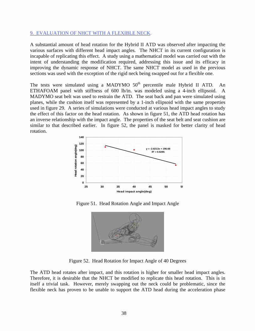
9. EVALUATION OF NHCT WITH A FLEXIBLE NECK. A substantial amount of head rotation for the Hybrid II ATD was observed after impacting the various surfaces with different head impact angles. The NHCT in its current configuration is incapable of replicating this effect. A study using a mathematical model was carried out with the intent of understanding the modification required, addressing this issue and its efficacy in improving the dynamic response of NHCT. The same NHCT model as used in the previous sections was used with the exception of the rigid neck being swapped out for a flexible one. The tests were simulated using a MADYMO 50th percentile male Hybrid II ATD. An ETHAFOAM panel with stiffness of 600 lb/in. was modeled using a 4-inch ellipsoid. A MADYMO seat belt was used to restrain the ATD. The seat back and pan were simulated using planes, while the cushion itself was represented by a 1-inch ellipsoid with the same properties used in figure 29. A series of simulations were conducted at various head impact angles to study the effect of this factor on the head rotation. As shown in figure 51, the ATD head rotation has an inverse relationship with the impact angle. The properties of the seat belt and seat cushion are similar to that described earlier. In figure 52, the panel is masked for better clarity of head rotation.
y = -2.6213x + 196.68R2 = 0.9295
0
20
40
60
80
100
120
140
25 30 35 40 45 50 55
Head impact angle(deg)
Hea
d ro
tatio
n an
gle(
deg)
Figure 51. Head Rotation Angle and Impact Angle
Figure 52. Head Rotation for Impact Angle of 40 Degrees
The ATD head rotates after impact, and this rotation is higher for smaller head impact angles. Therefore, it is desirable that the NHCT be modified to replicate this head rotation. This is in itself a trivial task. However, merely swapping out the neck could be problematic, since the flexible neck has proven to be unable to support the ATD head during the acceleration phase
38

when the actuator is firing. This requires the development of a rigid neck bracket to support the head during acceleration and then to disengage prior to impact with the target surface. The modification and its effect on the HIC results were studied using multibody analytical tools. The rigid joint between the neck and the pendulum arm was changed to a spherical joint with the required flexion and torsional joint stiffness to emulate the ATD head kinematics when impacted on a surface with similar input parameters as depicted in figure 53. Figure 54 shows the simulation sequence for this modification.
Figure 53. Head Impact for Sled Test and NHCT With Flexible Neck on Polyethylene Pad
Figure 54. Simulation Sequence for NHCT With Flexible Neck
Figure 55 shows the resulting acceleration of the ATD head compared to the benchmark test. As
1 2 3
4 5 6
can be seen, the NHCT model with the flexible neck has a very similar acceleration profile to the FSST test. The output is tabulated in table 16.
39

0
20
40
60
80
100
0 100 200 300 400
Time(ms)
Acc
'G'
FSST # A03007
MADYMO_SLED_A03007
NHCT_FLEX_NECK
Figure 55. Comparison of Head Acceleration Profile for FSST and NHCT Model With
Flexible Neck
Table 16. Comparison of Flexible and Rigid Neck NHCT Model Results and Corresponding FSST Results
Parameters FSST
A03007
MADYMO Model NHCT/Flexible-Neck
H03007
MADYMO Model NHCT/Rigid-Neck
H03007 Head-impact angle (deg) 45.7 45.7 45.7 Head-impact velocity(ft/sec) 32.2 32.2 32.2 HIC 304.3 347.0 440.0 HIC window (ms) 28.0 28.0 43.0 Head c.g. peak acceleration (g’s) 52.0 75.0 82.0 Head c.g. avg. acceleration (g’s) 33.0 36.0 42.0 Table 17 shows the results of a parametric study using the FSST and the flexible neck NHCT model. Figure 56 shows correlations between the FSST and both the rigid neck NHCT and the flexible neck NHCT models. As can be seen, the flexible neck NHCT model shows a substantially improved trend and correlation. Further tests could be carried out with various impacting surfaces and correlation drawn between rigid neck and flexible neck.
40

Table 17. Comparison of FSST Results With Flexible Neck NHCT Model Results
FSST MADYMO Model of NHCT
With Analytical Flexible Neck
Test ID
Head Velocity (ft/sec)
Impact Angle
(degree) HIC Test ID
Head Velocity(ft/sec)
Impact Angle
(degree) HIC A03007 32.2 45.7 304 H03007 32.2 45.7 347 A03008 32.6 46.7 302 H03008 32.6 46.7 334 A03009 42.4 41.6 1047 H03009 42.4 41.6 1020 A03010 43.8 42.9 1044 H03010 43.8 42.9 920 A03011 38.7 40.6 667 H03011 38.7 40.6 870
Figure 56. Correlation Between FSST and NHCT With Rigid and Flexible Necks
10. RESULTS. This study presented a brief description of the NHCT and the latest modifications in the device. The device was aimed to produce a simple alternative method of compliance with the Head Injury Criteria (HIC) requirement for the certification of seats and interior cabin furnishings, as specified in 14 CFR 23.562 and 25.562. The performance of the device for various aircraft interior impact surfaces was compared to the performance of traditional FSST. The data was obtained from dynamic tests conducted at NIAR and CAMI as well as from occupant biodynamic models developed using MADYMO code.
y = 0.979xR2 = 0.8936
y = 0.7231xR2 = 0.8807
0
200
400
600
800
1000
1200
1400
1600
0 200 400 600 800 1000 1200 1400 1600HIC-TESTER
HIC
-SLE
D
Correlation LineFlexibleRigid
41

In general, it appears that for simple geometries, such as panels, the NHCT device tends to produce results that are close but slightly greater than the results from FSSTs. Thus, HIC for the NHCT are conservative for the cases tested. The effects causing descrepancies can be categorized into the following groups: • Variations in the behavior of the test articles. These variations, such as unpredictable
inertia-induced flexing of tall divider panels or different failure modes of tray tables, are unavoidable and difficult to correct.
• Variations caused by kinematic approximations in the NHCT. While the NHCT approximates a kinematic copy of the 50th percentile male Hybrid II ATD as closely as possible, some differences are present, such as lack of a flexible neck, incompressible spine, and a different lower torso friction properties. Simulations have shown that while the contribution of a flexible neck to the HIC may not be a substantial contributing factor in causing HIC values to vary from FSST values for simple target geometries, it could have a more pronounced effect for more complex targets, such as seat backs with tray tables. Designs for rectifying these limitations are available and can be implemented with relative ease.
• Variations in FSST-NHCT test conditions. As noted previously, HIC in general is extremely sensitive to test parameters, i.e., impact velocity and impact angle. This being the case, one would expect that validation of the NHCT would be difficult using a one-to-one comparison of the FSST and NHCT test data.
11. REFERENCES.
1. Chandler, R.F., “Human Injury Criteria Relative to Civil Aircraft Seat and Restraint Systems,” SAE Paper 851847, Society of Automotive Engineers, Warrendale, PA, 1985.
2. Lissner, H.R., Lebow, M., and Evans, F.G., “Experimental Studies on the Relation Between Acceleration and Intracranial Pressure Changes in Man,” Surgery, Gynecology, and Obstetrics, V. 111, 1960, pp 329-338.
3. Gadd, C.W., “Use of a Weighted Impulse Criterion for Estimating Injury Hazard,” SAE Paper 660793, Proceedings of the Tenth Stapp Car Crash Conference, Society of Automotive Engineers, Warrendale, Pennsylvania, 1966, pp. 16-174.
4. Versace, J., “A Review of the Severity Index,” SAE Paper 710881, Proceedings of the Fifteenth Stapp Car Crash Conference, Society of Automotive Engineers, Warrendale, Pennsylvania, 1971, pp. 771-796.
5. Gurdjian, E.S., Lissner, H.R., Latimer, F.R., Haddad, B.F., and Webster, J.E.,
“Quantitative Determination of Acceleration and Intercranial Pressure in Experimental Head Injury,” Neurology 3,4, 1953, pp. 4223.
42
6. Gurdjian, E.S., Roberts, V.L. and Thomas, L.M., “Tolerance Curves of Acceleration and Intercranial Pressure and Protective Index in Experimental Head Injury,” J. of Trauma, Vol. 6, 1964, pp. 600.
7. “Department of Transportation (1971) Occupant Crash Protection-Head Injury Criterion,” NHTSA Doc Number 69-7, Notice 19, S6.2 of FMVSS 208, March 1971.
8. Title 14 Code of Federal Regulations, Part 23, Amendment 23-39, Section 23.562, published in the Federal Register, August 14, 1988.
9. Title 14 Code of Federal Regulations, Part 25, Amendment 25-64, Section 25.562, published in the Federal Register, May 17, 1988.
10. Hooper, S.J., Lankarani, H.M., and Mirza, M.C., “Parametric Study of Crashworthy Bulkhead Designs,” FAA report, DOT/FAA/AR-02/103, December 2002.
11. Lankarani, H., “Development of a Component Head Injury Criteria (HIC) Tester for Aircraft Seat Certification—Phase 1,” FAA report, DOT/FAA/AR-02/99, November 2002.
12. MADYMO V6.2, TNO Automotive, May 2004.
13. DeWeese, Richard L. and Moorcroft, David M., “Evaluation of a Head Injury Criteria
Component Test Device” Office of Aerospace Medicine, Washington, DC, 20591, DOT/FAA/AM-04/18.
43/44