Development of a CAD Template of the Front Cooler...
65
Development of a CAD Template of the Front Cooler Pack Improving packaging quality with a flexible and stable CAD model Master’s thesis in Product Development MSc MAGNUS BERTILSON Department of Product and Production Development CHALMERS UNIVERSITY OF TECHNOLOGY Gothenburg, Sweden 2017
-
Upload
truongthien -
Category
Documents
-
view
215 -
download
0
Transcript of Development of a CAD Template of the Front Cooler...

Development of a CAD Template of the
Front Cooler Pack
Improving packaging quality with a flexible and stable CADmodel
Master’s thesis in Product Development MSc
MAGNUS BERTILSON
Department of Product and Production DevelopmentCHALMERS UNIVERSITY OF TECHNOLOGYGothenburg, Sweden 2017


Development of a CAD Template of the Front Cooler Pack
Improving packaging quality with a flexible and stable CAD model
MAGNUS BERTILSON
Department of Product and Production DevelopmentProduct Development
CHALMERS UNIVERSITY OF TECHNOLOGYGothenburg, Sweden 2017

Development of a CAD Template of the Front Cooler Pack
MAGNUS BERTILSON
© MAGNUS BERTILSON, 2017.
Supervisors:Kristina Wärmefjord, Chalmers University of TechnologyFriedrich Bosch, Volvo Car Corporation
Examiner:Kristina Wärmefjord, Chalmers University of Technology
Department of Product and Production DevelopmentDivision of Product DevelopmentChalmers University of TechnologySE-412 96 GothenburgTelephone +46 31 772 1000
Cover: A visualization of the front cooler pack in a Volvo V40. Further cooling systeminformation can be found in Chapter 2.
iv

AbstractVolvo Cars continuously strives to improve the vehicle development process. One of thedevelopment activities during the development process is the packaging of the vehiclecomponents. One of improving the development process is by reducing the packagingtime and increasing the packaging quality. In this report, a working method for reducingthe packaging time and increasing the packaging quality of some cooling components hasbeen applied.
The master’s thesis was carried out at the department Cooling System at Volvo Cars. Thegoal of the thesis was to create a CAD model of the cooler pack that would decrease thepackaging time and increase the packaging quality. The CAD model was targeted to beapplied during the early phases of the packaging of the cooler pack.
The final concept is a CAD model that has the potential of reaching the set goal.
Keywords: Cooling system, packaging quality, packaging time, CAD template, Coolerpack
v


AcknowledgementsThe work presented in this master’s thesis was carried out at Volvo Car Corporation at thedepartments CAD & Mechanical Development and Cooling System Outer. I would liketo thank the the people who has helped me during the master’s thesis.
A special thanks to:
Stefan Molen, my manager at Cooling System Outer, for providing me with the opportu-nity to write this master’s thesis.
Friedrich Bosch, my supervisor at CAD & Mechanical Development, for all the valuableguidance and support throughout the project.
Kristina Wärmefjord, my supervisor at Chalmers University of Technology, for the sup-port and help during the project.
I want to say thank you to Kristofer Hansson, Bo Hansson, Helena Martini and all othercolleagues at the Cooling System Outer department and at the CAD & Mechanical De-velopment department for providing me with valuable inputs.
Magnus Bertilson, Gothenburg, June 2017
vii


NomenclatureAC Air ConditioningBEV Battery electric vehicleBuild to print Manufacturing detailCATIA V5 Currently used CAD program at Volvo CarsComplete Cooler Pack The heat exchangers and the fan of the
cooling systemCEVT China Euro Vehicle TechnologyDoF Degrees of FreedomEBOM Engineering Bill Of Material. Bill of Material
is the term used to describe the "parts list" ofcomponents needed to complete a sell-able end-item
ESOW Engineering Statement of WorkLTR Low temperature radiatorHTR High temperature radiatorMATLAB Multi-paradigm numerical computing environmentNVH zones Noise, Vibration and Harshness ZonesPS Project start for a new vehicle programRD Bottle Receiver & Dryer BottleSCR Selective Catalytic ReductionVolvo Car Corporation "Volvo Cars"
ix

x

Contents
List of Figures xiii
List of Tables xv
1 Introduction 11.1 Volvo Car Corporation . . . . . . . . . . . . . . . . . . . . . . . . . . . 11.2 Project Background . . . . . . . . . . . . . . . . . . . . . . . . . . . . . 11.3 Project Purpose . . . . . . . . . . . . . . . . . . . . . . . . . . . . . . . 21.4 Project Goal . . . . . . . . . . . . . . . . . . . . . . . . . . . . . . . . . 21.5 Project Deliveries . . . . . . . . . . . . . . . . . . . . . . . . . . . . . . 21.6 Limitations . . . . . . . . . . . . . . . . . . . . . . . . . . . . . . . . . 2
2 Theory 32.1 Volvo Car Corporation’s Car Models & Platforms . . . . . . . . . . . . . 32.2 Cooling System . . . . . . . . . . . . . . . . . . . . . . . . . . . . . . . 3
2.2.1 High Temperature Radiator . . . . . . . . . . . . . . . . . . . . . 52.2.2 Low Temperature Radiator . . . . . . . . . . . . . . . . . . . . . 52.2.3 Condenser . . . . . . . . . . . . . . . . . . . . . . . . . . . . . 62.2.4 Fan . . . . . . . . . . . . . . . . . . . . . . . . . . . . . . . . . 6
2.3 Propulsion Systems and Cooler Packs . . . . . . . . . . . . . . . . . . . 72.3.1 Combustion Engines . . . . . . . . . . . . . . . . . . . . . . . . 72.3.2 Electrical Propulsion Systems . . . . . . . . . . . . . . . . . . . 7
2.4 CAD Template . . . . . . . . . . . . . . . . . . . . . . . . . . . . . . . 82.4.1 The Need for CAD Templates . . . . . . . . . . . . . . . . . . . 82.4.2 CAD Template Example . . . . . . . . . . . . . . . . . . . . . . 82.4.3 Generative Shape Design and Knowledge Advisor in CATIA V5 . 10
3 Methodology 113.1 Planning . . . . . . . . . . . . . . . . . . . . . . . . . . . . . . . . . . . 113.2 Concept Development . . . . . . . . . . . . . . . . . . . . . . . . . . . . 12
3.2.1 Identifying Customer Needs . . . . . . . . . . . . . . . . . . . . 123.2.2 Product Specifications . . . . . . . . . . . . . . . . . . . . . . . 123.2.3 Concept Generation . . . . . . . . . . . . . . . . . . . . . . . . 123.2.4 Concept Screening and Selection . . . . . . . . . . . . . . . . . . 13
3.3 System-Level Design . . . . . . . . . . . . . . . . . . . . . . . . . . . . 133.4 Detail Design . . . . . . . . . . . . . . . . . . . . . . . . . . . . . . . . 133.5 Testing and Refinement . . . . . . . . . . . . . . . . . . . . . . . . . . . 13
xi

Contents
3.6 Company Knowledge Value Stream . . . . . . . . . . . . . . . . . . . . 14
4 Project Work 154.1 Knowledge Acquisition . . . . . . . . . . . . . . . . . . . . . . . . . . . 15
4.1.1 Cooling System Study . . . . . . . . . . . . . . . . . . . . . . . 154.1.2 Current Packaging Process of the Cooler Pack . . . . . . . . . . . 164.1.3 Flexible Modelling Study . . . . . . . . . . . . . . . . . . . . . 16
4.2 Customer Needs and Target Specifications . . . . . . . . . . . . . . . . . 174.3 Concept Generation . . . . . . . . . . . . . . . . . . . . . . . . . . . . . 18
4.3.1 Clarify the Problem . . . . . . . . . . . . . . . . . . . . . . . . . 184.3.2 Search Externally . . . . . . . . . . . . . . . . . . . . . . . . . . 194.3.3 Search Internally . . . . . . . . . . . . . . . . . . . . . . . . . . 19
4.4 Concept Selection . . . . . . . . . . . . . . . . . . . . . . . . . . . . . . 224.4.1 Concept Screening . . . . . . . . . . . . . . . . . . . . . . . . . 224.4.2 Refinement of the Winning Concepts . . . . . . . . . . . . . . . 234.4.3 Concept Scoring . . . . . . . . . . . . . . . . . . . . . . . . . . 25
4.5 Testing and Refinement . . . . . . . . . . . . . . . . . . . . . . . . . . . 254.6 System-Level Design . . . . . . . . . . . . . . . . . . . . . . . . . . . . 27
4.6.1 High Temperature Radiator . . . . . . . . . . . . . . . . . . . . . 274.6.2 Low Temperature Radiator . . . . . . . . . . . . . . . . . . . . . 314.6.3 The Condenser . . . . . . . . . . . . . . . . . . . . . . . . . . . 314.6.4 The Fan . . . . . . . . . . . . . . . . . . . . . . . . . . . . . . . 33
4.7 Design for User Experience . . . . . . . . . . . . . . . . . . . . . . . . . 33
5 Results 355.1 Final Thesis Concept . . . . . . . . . . . . . . . . . . . . . . . . . . . . 35
5.1.1 Customer Needs Fulfillment . . . . . . . . . . . . . . . . . . . . 36
6 Conclusion and Recommendations for Future Work 396.1 The Master’s Thesis Conclusion . . . . . . . . . . . . . . . . . . . . . . 396.2 Recommendations for Future Work . . . . . . . . . . . . . . . . . . . . . 40
7 Discussion & Lessons Learned 417.1 Relevance of the Task and the Objectives . . . . . . . . . . . . . . . . . . 417.2 Methodology . . . . . . . . . . . . . . . . . . . . . . . . . . . . . . . . 417.3 Lessons Learned . . . . . . . . . . . . . . . . . . . . . . . . . . . . . . 41
Bibliography 43
A Mission Statement I
B Customer Needs List & Target Specifications III
C Project Time Table V
xii

List of Figures
2.1 Rough schematic cooling system overview. . . . . . . . . . . . . . . . . 42.2 One type of a front cooler pack. 1 = The Fan. 2 = The high temperature
radiator. 3 = The condenser. 4 = The low temperature radiator . . . . . . 42.3 Illustration of HTR’s main circuit: the cooling of the combustion engine.
In the right hand picture horizontal designed tubes and cooling fins arehighlighted. . . . . . . . . . . . . . . . . . . . . . . . . . . . . . . . . . 5
2.4 The four main components of the AC circuit. . . . . . . . . . . . . . . . 62.5 The four cylinder front cooler pack. Black arrow demonstrate the driving
direction. . . . . . . . . . . . . . . . . . . . . . . . . . . . . . . . . . . 72.6 The BEV front cooler pack . . . . . . . . . . . . . . . . . . . . . . . . . 72.7 Illustrations of the CAD template of the box. . . . . . . . . . . . . . . . . 92.8 The steps for changing a geometrical value with the sketch-based approach. 9
3.1 Ulrich & Eppinger’s product development process . . . . . . . . . . . . . 11
4.1 Comparison between a packaging model and the supplier final model ofa cooler pack. . . . . . . . . . . . . . . . . . . . . . . . . . . . . . . . . 16
4.2 Main customer needs . . . . . . . . . . . . . . . . . . . . . . . . . . . . 174.3 Black box of the early phase packaging and development of the cooler pack 184.4 The parameter tree structure and one programming code of a CAD template 194.5 The Tot Rot, 6DoFs and 3DoFs 2D concepts . . . . . . . . . . . . . . . . 204.6 The Parking Sensor concept . . . . . . . . . . . . . . . . . . . . . . . . 214.7 The Packaging concept . . . . . . . . . . . . . . . . . . . . . . . . . . . 214.8 The concept-screening matrix . . . . . . . . . . . . . . . . . . . . . . . . 224.9 3D concept. One or two fans can quickly and easily be alternated with the
roll-down parameter . . . . . . . . . . . . . . . . . . . . . . . . . . . . . 244.10 3D concept of 6DoFs. Parameters for translation and rotation can be seen. 254.11 The concept-scoring matrix. . . . . . . . . . . . . . . . . . . . . . . . . 254.12 New (green) and old (blue) cross section design of the HTR. . . . . . . . 264.13 New HTR template design (green) and old HTR template design (blue) . 274.14 Parameter set of the coolant tank cross-section . . . . . . . . . . . . . . . 284.15 Restriction zone of the coolant tank . . . . . . . . . . . . . . . . . . . . 284.16 Illustration of different spigot geometries with parameter input. . . . . . . 294.17 Degas spigot on the negative y-side of the radiator and on the positive
y-side of the radiator. . . . . . . . . . . . . . . . . . . . . . . . . . . . . 294.18 Bushing seen from the left side (in the driving direction) and from a rear
view. . . . . . . . . . . . . . . . . . . . . . . . . . . . . . . . . . . . . . 30
xiii

List of Figures
4.19 Production used holder and the template solution . . . . . . . . . . . . . 304.20 HTR geometries seen from the rear view in the driving direction . . . . . 314.21 LTR geometries seen from the rear view in the driving direction . . . . . 314.22 The complete condenser, the two refrigerant pipes and angle of the pres-
sure sensor . . . . . . . . . . . . . . . . . . . . . . . . . . . . . . . . . 324.23 The RD bottle . . . . . . . . . . . . . . . . . . . . . . . . . . . . . . . . 334.24 Different fan layouts. . . . . . . . . . . . . . . . . . . . . . . . . . . . . 334.25 A to-do list used during an user test . . . . . . . . . . . . . . . . . . . . 344.26 Inputs on naming of parameter and parameter value . . . . . . . . . . . . 34
5.1 The final CAD template concept . . . . . . . . . . . . . . . . . . . . . . 355.2 BEV cooler pack . . . . . . . . . . . . . . . . . . . . . . . . . . . . . . 355.3 Fulfillment of the initial customer needs. . . . . . . . . . . . . . . . . . . 365.4 The ’supplier a’, the ’supplier b’ and the ’supplier c’ cross-section designs 36
B.1 List of the identified customer needs. 5 = high imporance. 1= low impor-tance . . . . . . . . . . . . . . . . . . . . . . . . . . . . . . . . . . . . . III
B.2 Target specifications . . . . . . . . . . . . . . . . . . . . . . . . . . . . III
C.1 Project Time Table . . . . . . . . . . . . . . . . . . . . . . . . . . . . . V
xiv

List of Tables
4.1 Initial geometrical detail list . . . . . . . . . . . . . . . . . . . . . . . . 234.2 HTR specification list . . . . . . . . . . . . . . . . . . . . . . . . . . . . 284.3 LTR specification list . . . . . . . . . . . . . . . . . . . . . . . . . . . . 314.4 Condenser specification list . . . . . . . . . . . . . . . . . . . . . . . . . 314.5 Fan specification list . . . . . . . . . . . . . . . . . . . . . . . . . . . . 33
xv

List of Tables
xvi

1Introduction
Volvo Cars strives to continuously improve their product development cycle. One im-provement target is to reduce the product development time. Quality [12] is one of VolvoCars’ core values. A reduction of development time shall therefore be mutually achievedwith increased product quality. This chapter presents detailed information regarding thebackground, the purpose and the goal of the project.
1.1 Volvo Car CorporationThe master’s thesis has been conducted at Volvo Cars. Volvo Cars is one the world’sbest-known car brands. Volvo Cars produces premium cars including sedans, wagons,sport wagons, cross country cars, hatchbacks and SUVs. Volvo Cars visions is to be theworld’s most progressive and desired premium car brand. Volvo Cars mission is to makelife less complicated for people, while strengthening their commitment to safety, qualityand the environment [11]. The headquarter is in Gothenburg, Sweden, production takesplace in Sweden, Belgium, China and Malaysia. The company is owned by ZheijangGeely Holding of China since 2010.
1.2 Project BackgroundCars are continuously exposed to new requirements. These can be e.g. legal requirements(e.g. emission regulations) or customer oriented requirements. As a result of the continu-ous drive to meet these requirements cars are built with increased system complexity andwith more components. As the system complexity rises and the number of componentsincrease, the packaging of the car components becomes more demanding. In addition tothis, Volvo Car Corporation has set a goal for the year of 2020 to significantly reducethe development time. Using methods to reduce the packaging time, accompanied withincreasing the packaging quality, is vital to stay competitive.
The restricted space in the car requires tests of many different geometrical shapes and po-sitions of the components before a suitable packaging solution can be established. Thesetests are done in a 3D computer environment using CAD programs. The packaging tests(packaging studies) are often prolonged because the CAD methods used are not favorablefor performing fast geometrical changes. One measure to decrease the packaging time isto use alternative CAD methods. A CAD template is such an alternative CAD method.CAD templates are used to speed up the development cycle and increase the packaging
1

1. Introduction
quality, hence shortening time and reducing cost. CAD templates facilitate fast geomet-rical changes and applies system and component know-how and are therefore suitable touse during packaging studies.
1.3 Project PurposeThe project outcome shall increase the packaging speed and the packaging quality of thefront cooler pack.
The thesis shall answer the following questions:1. How can a CAD template be created of the front cooler pack that decreases the
packaging time?2. How can a CAD template be created that increases the packaging quality of the
front cooler pack?
1.4 Project GoalDeliver a CAD template model that improves the packaging quality of the front coolerpack and decreases the packaging time.
1.5 Project Deliveries• CAD template of the front cooler pack• User Guide of the CAD template• Chalmers report on project work• Presentation at Chalmers University of Technology• Presentation at the Cooling System department
1.6 LimitationsListed are the project limitations. The limitations with an accompanied star have beenadded to the list during the project.
• *CAD template shall only include the following components:– the high temperature radiator– the low temperature radiator– the condenser– the fan
• Template is not purposed for build to print• No finite element calculations will be performed.• No flow or thermal calculations will be performed.• Template developed only for the CMA and the SPA platform
2

2Theory
This chapter presents theoretical knowledge about the topic that is necessary for the un-derstanding of the report’s content. First of all an introduction to Volvo Car Corporation’sdifferent car models is presented. Subsequently the purpose, working principle and com-ponents of the cooling system are presented. After the introduction to the cooling system,the different propulsion systems of Volvo Car Corporation’s cars are presented. At theend of the chapter CAD templates are explained.
2.1 Volvo Car Corporation’s Car Models & Platforms
Volvo Car Corporation offer three car series; the 40 series, the 60 series and the 90 series.The 90 series and 60 series share the same platform, the Scalable Product Architecture(SPA) platform. The upcoming 40 series is to be built on the Compact Modular Archi-tecture (CMA) platform. The CMA platform is shared between Volvo Car Corporationand CEVT. Both platforms are designed for combustion engines and hybrid propulsionsystems.
2.2 Cooling System
The purpose of the cooling system is to keep components in need of cooling at desiredoperating temperatures and provide cooled fluid to the AC system. The components ra-diating heat from the coolants and the refrigerant are assembled together in the front ofthe engine compartment. In this report these components are called the front cooler pack.Figure 2.1 illustrates two of the cooling circuits of the cooling system. The thicker arrowsshows the cooling circuit between the high temperature radiator and the engine. The thin-ner arrows illustrate the cooling circuit in the AC system (condenser to evaporator).
3

2. Theory
Figure 2.1: Rough schematic cooling system overview.
The components of the front cooler pack are heat exchangers (excluding the fan). Heatexchangers are devices that facilitate the exchange of heat between two fluids that are atdifferent temperatures while keeping them from mixing with each other [4]. Heat transferin a heat exchanger usually involves convection in each fluid and conduction throughthe wall separating the two fluids. The heat exchangers in this report are liquid-to-airheat exchangers, which in practise means that the cooling fluids radiate their heat to thesurrounding air. One type of front cooler pack can be seen in Figure 2.2.
Figure 2.2: One type of a front cooler pack. 1 = The Fan. 2 = The high temperatureradiator. 3 = The condenser. 4 = The low temperature radiator
In the top left picture the fan and its shroud (see chapter 2.2.4) can be seen from a rearoblique view. The fan is mounted in the rear of the cooler pack. In the right hand picture
4

2. Theory
the high temperature radiator (yellow colored manifolds) and the condenser (silver col-ored manifolds) can be seen (see chapters 2.2.1 and 2.2.3).
Performance-wise, there are two main requirements on the cooling system; to cool theengine during trail tow or hill climbing and to cool the AC system during city drivingor idling. The cooling performance of the heat exchangers are highly dependent on theambient air temperature and the air flow. Low ambient air temperature and a big air floware beneficial for the heat exchange. The ambient air temperature can not be changed, butthe air flow can be increased with a bigger heat exchanger area. Hence, the main designtarget of heat exchangers is to design the cooling core as big as possible. The followingsub-chapters describes the purpose and working method of the cooling components of thefront cooler pack for four cylinder engines and BEV vehicles (see 2.3.1 and 2.3.2).
2.2.1 High Temperature RadiatorThe high temperature radiator (HTR) is the main heat exchanger in the cooling system.The HTR radiates heat from the combustion engine with a coolant flowing through theHTR and the engine. For automatic shifted cars a part of the radiator core is devoted tocool the coolant for use in transmission cooling. In Figure 2.3 the cooling circuit of thecombustion engine is displayed.
Figure 2.3: Illustration of HTR’s main circuit: the cooling of the combustion engine. Inthe right hand picture horizontal designed tubes and cooling fins are highlighted.
Coolant from the HTR flows to the engine where it absorbs heat from the engine. Aftercooling the engine the coolant flows back to the HTR where the heat from the engine isradiated to the air flowing through the HTR. The HTR consist of a rectangular core withtubes and fins, inlet and outlet tanks with accompanying inlet and outlet spigots, one airrelease spigot, one drainage tap, and holders for mounting to the vehicle structure.
2.2.2 Low Temperature RadiatorThe low temperature radiator (LTR) uses the same working principle as the high tem-perature radiator, but it radiates heat from other cooling circuits. The low temperatureradiator is used to cool circuits of the propulsion system that demands a lower operat-ing temperature. The low temperature radiator consists of a core with tubes and fins,
5

2. Theory
and inlet and outlet tanks with accompanying inlet and outlet spigots. Depending on thegiven propulsion system the low temperature radiator can be designed with an additionalcooling circuit running through it.
2.2.3 Condenser
The condenser is one of the heat exchangers in the AC system. The AC system uses arefrigerant to adjust the air temperature of the AC air in the passenger compartment. Thecondenser is the part in which the refrigerant undergoes a change from gaseous stage toliquid stage. The condenser is an aluminum part that consists of a core, inlet and outletpipes, one pressure sensor and a dryer bottle. Inside the dryer bottle there is a desiccantbag that will absorb the water in the refrigerant. The bottle is also a buffer of refrigerant.A car condenser uses the same working principle as a refrigerator, see Figure 2.4.[7]
Figure 2.4: The four main components of the AC circuit.
The first step of the process is the delivery of cooled high-pressure liquid from the con-denser. The refrigerant flows through a thermostatic expansion valve (TXV). The TXVcontrols the rate of flow of liquid refrigerant into the evaporator. As the flow is restricted,the pressure on the liquid drops [1]. In the evaporator the low pressure liquid absorbsheat from the air flow to the passenger compartment and by doing so evaporates. This en-ables the temperature of the AC air to be adjusted. The evaporator delivers low-pressureheated gas to the compressor which compresses the gas to a high-pressure state. Thehigh-pressure gas subsequently condensates in the condenser.
2.2.4 Fan
The cooling performance is dependent on mainly two parameters; the ambient air tem-perature and the amount of air flow running through the cooler pack. The purpose of thefan is to generate additional air flow through the cooler pack, e.g. during standstill. Thediameter of the fan shall be as big as possible to increase the air flow through the heatexchangers. Depending on the shape of the complete cooling kit, an additional fan can beadded.
6

2. Theory
2.3 Propulsion Systems and Cooler PacksThis sub-chapter serves to provide a short explanation of the relation between the differentpropulsion systems and the cooler packs.
2.3.1 Combustion EnginesThe engines used in Volvo Car Corporation’s cars are four cylinder petrol or diesel en-gines. The cooler pack for the four cylinder engine consist of one fan (1), one high tem-perature radiator (2), one low temperature radiator (3) and one condenser (4) (see figure2.5).
Figure 2.5: The four cylinder front cooler pack. Black arrow demonstrate the drivingdirection.
2.3.2 Electrical Propulsion SystemsBEV is an abbreviation that stands for battery electric vehicle. The BEV is driven byan electric engine. An electrical propulsion system does not contain a high temperaturecircuit (due to the absence of the combustion engine). Hence, the HTR is excluded in thecomplete cooling kit. The complete cooling kit consists of the fan (1), the LTR (2) andthe condenser (3), see figure 2.6.
Figure 2.6: The BEV front cooler pack.
7

2. Theory
2.4 CAD TemplateThe abbreviation CAD stands for Computer Aided Design. CAD programs are widelyused within the car industry. With the tools of a CAD program, 3D models can be cre-ated. CAD has become a substitute for manual drafting of cars and car parts. Additionallyin CAD e.g. finite element calculations can be carried out, 2D sketches can be createdand animations can be developed. The CAD program used in this report is CATIA V5.In the following subsections the need for CAD templates and what a CAD template is arepresented.
2.4.1 The Need for CAD TemplatesA conventional approach for creating parts in CATIA V5 is sketch-based design. Sketch-based means that a part is created from a 2D sketch. In the sketch the dimensions andmeasurements of a cross-section of the part are specified. Following the completion ofthe sketch, a 3D geometrical shape is created. Step-by-step a complete part is created.The main benefit of the sketch-based approach is the possibility of creating a precise ge-ometry of the part. The drawback of the sketch-based approach is the ability to carry outredesign changes. The redesign of a sketch-based part might be troublesome and verytime consuming. These long lead times are very disadvantageous, because the productdevelopment cycle of a car part requires numerous redesign before a suitable design iscreated. To reduce the redesign lead times, CAD templates are used. CAD templatemodels are structured in order to facilitate redesign changes, hence they are suited fordevelopment of car parts and systems. An example of a CAD template is presented inchapter 2.4.2.
The CAD templates main objective is to generate greater design maturity in early phasesin order to reduce firefighting in later phases (C.Hansson, personal communication, 5thof May 2017). To reach this objective CAD templates needs to be flexible and stable,in other words: not sensitive to geometrical changes. By using CAD templates quality,efficiency and lead time can be improved. In the next sub-chapter an example of a CADtemplate is presented.
2.4.2 CAD Template ExampleA hypothetical case will be used to present what a CAD template is. In this hypotheticalcase a box shall be developed with parametrization. This box shall be designed with asquare shaped cross-section. The sides and the length of the box shall be flexible. Thereshall be a hole through the box. This hole’s radius and position in the z direction shall beflexible. An additional requirement is that the model shall be able to change geometricalshapes quickly and easily.
The first step in creating this kind of model is to design the geometry. The second step is
8

2. Theory
to connect the measurements of the model to different parameter sets. This is done withthe implemented programming tools in CATIA V5. In Figure 2.7 the parameter sets Boxand Hole and their respective parameters can be seen.
Figure 2.7: Illustrations of the CAD template of the box.
When these parameters are connected to the measurements of the model, changes canbe done by double-clicking the parameters and setting a new value. This approach iscalled parametrization. The CAD template model requires only two steps for changinga geometrical value. This can be compared to the sketch-based approach which for thisspecific example would require four steps. The steps are demonstrated in Figure 2.8.
Figure 2.8: The steps for changing a geometrical value with the sketch-based approach.
It shall be taken into account that in this example the model is very simple. In the carindustry, much more complex geometries are created. To change one single geometri-cal value in sketch-based model demands a lot of searching in the model tree or evenre-structuring of the model. With a parameter build model, only two steps are needed.Therefore, the parametrization creates a very user-friendly model for these kinds of op-erations. This CAD approach demands more work when creating the model comparedto the sketch-based approach, but is advantageous to use when in need of changing theshape of a part or distance to an object. Since much time is spent adjusting the positionof a car part or redesigning it, a lot of time can be saved by using CAD templates.
CAD templates are further used to build in know-how into the CAD models. In the boxexample know-how could be implemented by informing the designer that a minimumthickness of x mm has to be kept between the edge of the circle and the edges of the box.
The main challenge when creating CAD templates is to adequately assume what needs tobe flexible of the model. In the hypothetical box example the requirements (e.g. squarecross-section, changeable radius and position of the hole) are stated. But if the design
9
2. Theory
engineer wants to try to design the box with two smaller holes instead of one big, themodel has to be redone. If such a scenario is probable, this flexibility must be built intothe CAD template.
The combination of successful parametrization and build in know-how creates CAD mod-els that are fast and can increase the quality of the packaging and development of the carparts. In the next sub-chapter the two main workbenches in CATIA V5 for creating CADtemplates are briefly explained.
2.4.3 Generative Shape Design and Knowledge Advisor in CATIAV5
Generative Shape Design (GSD) is the workbench in CATIA V5 in which surface modelscan be created. Stable CAD models can be developed by using planes, axes and pointsas driving geometries of the CAD model. The Knowledge Advisor (KA) workbench pro-vides the user with tools for programming of the CAD model. Parameter-driven CADmodels can be created by using the programming tools of the Knowledge Advisor work-bench. Parameter driven CAD models can, as described in 2.4.2 change e.g. geometricalshapes and positions or add or remove different features quickly compared to CAD mod-els exclusively modelled in the Part or GSD workbench. Building CAD models that arestable is called flexible modelling.
10

3Methodology
The structure of this thesis work has been based on the methods presented by Ulrich &Eppinger [10]. The process is a well-known and acknowledged product developmentmethodology. The methodology includes methods and tools for development of productswith the main goal of creating value for the customer.This master thesis extends from the planning phase to the testing phase, see Figure 3.1.Applicable methods with the potential of increasing the success of the project’s outcomehas been used. CATIA V5 has been used for the development of the Template model.
Figure 3.1: Ulrich & Eppinger’s product development process
3.1 PlanningPlanning is the first phase of the six development phases presented by Ulrich & Eppinger.The planning phase is also referred to as phase zero being the preceding phase to the ac-tual project launch. One output of the planning phase is the mission statement which isa document providing information concerning the product (e.g. benefits proposition, keybusiness goals and primary market). The mission statement shall during the developmentprocess guide the development team in the wanted direction.
A second output of the planning phase is the time table. The time table shall be createdby identifying the project goal, followed by identifying necessary development activities
11

3. Methodology
and finally organize the development activities timewise in order to reach the project goalin time.
3.2 Concept Development
Ulrich & Eppinger’s key message for successful product development is to identify themarket’s needs and create a product that fulfills these needs. Therefore, the concept de-velopment starts with identification of the customer needs. The next step is to create aproduct specification list. This list addresses the customer needs in product related terms.Based on the product specification list concepts are generated and selected. The followingsubsections describes these steps.
3.2.1 Identifying Customer Needs
A customer’s needs list is also called the language of the customer. The list’s key benefitsare: it enables a customer oriented concept development and that no critical customerneed is left out or suppressed. The goal is to gather the explicit and implicit needs fromthe customers of the target market. Especially lead users are beneficial to gather data frombecause they experience needs before regular users. In the context of this project, the leadusers are the engineers developing the cooler kit at Volvo Car Corporation. The identifiedcustomer needs are used as input for the creation of the product specifications.
3.2.2 Product Specifications
The product specifications shall give guidance during the concept development to createa successful product. The product specifications shall translate the customer needs intoproduct specified features and functions, make the future product to stand out from thecompetitors and be technically and economically feasible. The product specifications listis at least established twice. The first list is called target specifications. According toUlrich & Eppinger the target specifications symbolizes the high hopes and initial goalsof the development team before sufficient knowledge is gathered. Therefore, these targetspecifications are reviewed and updated during the concept development as new relevantknowledge is acquired.
3.2.3 Concept Generation
During this phase multiple product concepts are generated to address the identified needsand the product specifications. It is a highly creative phase during which the developmentteam might generate hundreds of concepts. During the phase iteration is very probable,especially when developing new kind of products. The output of the phase is a couple ofconcepts. These concepts shall be evaluated against each other during the screening andselection phase. In this project the concept generation shall starts with 2D sketches of theconcepts and evolve into 3D model of some concepts before the concept screening.
12

3. Methodology
3.2.4 Concept Screening and SelectionThe concept screening and selection are done to identify the most promising generatedconcept or concepts based on the customer needs and other relevant criteria. The PughMatrix and the Kesselring Matrix are matrices for concept evaluation. These matrices canbe seen as filters that let through concepts based on their strengths and weaknesses withregard to the list of criteria. Another benefit of the matrices is that visual documentationof the decision-making process is established. During this project the criteria for choiceof concepts shall be derived from the product specification list and customer needs list.Additionally alpha prototype tests shall be carried out during the selection of concepts.Read more detailed description about alpha prototyping in the chapter 3.5.
3.3 System-Level DesignThe purpose of the system-level design phase is to develop a more structured and detaileddesign of the chosen concept. The phase includes the definition of the product archi-tecture, decomposition of the product into subsystems and components, and preliminarydesign of key components. The system-level design phase shall additionally facilitate thephysical assembly process of the product. Since the final product of this project shall bea CAD model, no preparation activities for physical manufacturing shall be performed.
3.4 Detail DesignThis phase includes the final specification of the product; e.g. drawings and computermodels of the product, material selection, tolerances for production, production cost etcetera. For a physical product the phases involves the methods Design for Environment,Design for Manufacturing and Robust Design, but for this project foremost Design forUse shall be the focus (since no physical product is to be produced). Design for use isimportant because a template model needs an user interface that is easy to understand.Therefore, knowledge and methods from the area of design for use and User experienceshall be implemented [8].
3.5 Testing and RefinementThe testing and refinement phase is for testing alpha and beta prototypes. Alpha proto-types possess production-intent parts, i.e. parts with same geometry and material proper-ties as the intended final production version of the product. Alpha prototypes are used toevaluate if the product fulfills the customer’s needs. The beta prototype evaluates the per-formance and reliability of the product to create input for necessary engineering changesbefore the final product is defined. Since the final product of this project is a CAD model,the lead times for creating prototypes are very short. Getting inputs from the customercontinuously during the product development phases is beneficial for assuring that cus-tomer needs are met and for gathering of new needs. Therefore, testing of prototypes wasdecided to be run continuously during the development of the concepts.
13

3. Methodology
3.6 Company Knowledge Value StreamThis subsection is not a part of the Ulrich & Eppinger methodology. Its included becausedocumentation of work is a critical activity for sharing and maintaining knowledge withina company. It is important for a company that tacit knowledge is made explicit and spread[6]. To ensure that the findings of this project are spread accordingly within the company,both a user guide and a report were decided to be project deliveries (see chapter 1.5).The user guide includes a description of the template model structure and the parameterstructure of the template model. The documentation is decisive for the ease of use of thetemplate model. The documentation shall make it possible for a Volvo Car Corporationcolleague to study how to use the template model without aid of the model creator. Thisreport is purposed to describe the project without the presence of the author.
14
4Project Work
This chapter presents the actual project work. The implementation of Ulrich & Eppinger’smethodology is outlined as well as the outcomes of the various methods and tools. Thecontent of the chapter extends from the project start (February 2017) until the refinementphase of the final concept (May 2017). The project time table can be seen in Appendix C
The initial task of the master’s thesis was to develop a template of the high temperatureradiator. The task was soon to be extended to include the complete cooler pack. Thereason behind this extension was inputs from Cooling System Outer (B. Hansson, per-sonal communication, March 7th 2017) that said that the packaging and development ofthe high temperature radiator were done as a package accompanied by some additionalcooling components (the condenser, the fan and the low temperature radiator.). Therefore,the scope of the template was chosen to include the HTR, the fan, the condenser and theLTR.
4.1 Knowledge Acquisition
The first step of the project was to gain basic knowledge about the project topic. Duringthis pre-study phase, three sub studies were done: a study of the cooling system, a studyof the current packaging process of the cooler pack and a study about flexible modellingand CAD templates.
4.1.1 Cooling System Study
The study of the cooling system was vital to reach a knowledge level to be able to createa CAD template of the cooler pack. The main source of information about the compo-nents was an internal Volvo Car Corporation document. In this document the coolingsystem and its components are technically described and e.g. lessons learned from pre-vious projects are documented. For further gathering of data, meetings were held withthe component responsible of each front cooler kit component. The need of studying thecooling system as a whole and each component individually was necessary to establish anunderstanding of the working principle of the system and the working principles of eachcomponent. The features of the components that should be included in the CAD templatewere identified and documented. The initial list can be seen in chapter 4.4.2. Generalinformation about the cooling system can be found in chapter 2.
15

4. Project Work
4.1.2 Current Packaging Process of the Cooler Pack
The first step during the packaging process of the cooler pack is to create the model ge-ometry. The size and the position of the components are governed by the needed coolingperformance. The needed cooling performance is ruled by the type of propulsion system,engine power, component materials et cetera (Fredrik Tholander, personal communica-tion, 2017-03-17). When the required cooling performance is provided to the responsibledesign engineer of the cooler pack, the geometry is created based on previous cooler packswith similar cooling performance. These models consist of the most space critical detailsand shapes of the cooler pack. During the packaging and development process more low-level details are added. The difference between the packaging model used during the earlydevelopment phases and the final cooler pack can be seen in Figure 4.1
Figure 4.1: Comparison between a packaging model and the supplier final model of acooler pack.
In Figure 4.1 it can be seen that during the early development phases very simplifiedgeometries are used. The geometry of the cooler pack is continuously refined during thepackaging and development phases until a suitable solution is identified. When a suitablesolution is generated, suppliers are contacted. The suppliers provide models similar to thefinal packaging concept which is positioned at the targeted position in the car. The coolerpack CAD models have been created using the sketch-based approach. Since the coolerpack and its components need continuous redesigns until a suitable packaging solution canbe found, a CAD template has been identified as a solution for decreasing the developmentand packaging time.
4.1.3 Flexible Modelling Study
A CAD template is developed by using flexible modelling methods. Before starting withthe template development it was necessary to study how to create flexible CAD models.Therefore, the four day long Volvo Car Corporation course CAD Advance. Flexible Mod-elling was taken. The outcome of the course was valuable CATIA V5 knowledge thatfacilitated independent development work of the CAD template.
16

4. Project Work
4.2 Customer Needs and Target SpecificationsAfter finishing the pre-study of the cooling system a mission statement was compiled (seeAppendix A). The main customer was identified to be the design engineer carrying outthe early phase packaging study of the cooler pack. The secondary customers were identi-fied to be the component responsible and Volvo Car Corporation engineers and managersinvolved in the packaging of the cooler pack during packaging meetings.The next step of the process was to identify the needs of the different customers. The pro-cess of identifying the customer’s needs was planned according to the four step processrecommended by Ulrich & Eppinger:
1. Gather raw data from the customers2. Interpret the raw data in terms of customer needs3. Organize the needs into a hierarchy4. Establish the relative importance of the needs
Meetings were held with design engineers who worked with the packaging of the coolerpack to gather raw data. It was made clear during these meetings that the benefits of cre-ating a template of the cooler pack could not be perceived by the intended future users.The main reason for doubting the usefulness of a cooler pack template was because it isdifficult to predict what needs to be changed during the packaging process (B.Hansson,personal communication, 2017-03-07). Due to the doubtfulness, no further customer in-puts were provided by Cooling System Outer.
The needs of the secondary customers were known at project start (F. Bosch, personalcommunication, 2017-02-28). One main activity during packaging meetings is to discusspackaging collisions between different vehicle components. A recurring scenario is thatone or more colliding components are in need of redesigns. One mean of increasingthe efficiency and effectiveness of packaging meetings is to carry out redesign changesduring packaging meetings. Therefore, they wanted a CAD model that could change itsgeometrical shape and position quickly. The model should be easy to use, because userswith little CATIA V5 experience would use it.A summary of the most vital customer needs are summarized in Figure 4.2. The completecustomers needs list and the target specifications can be found in the Appendix B.
Figure 4.2: Main customer needs
17

4. Project Work
As the customer needs were identified and the target specifications set, the concept gen-erations was launched.
4.3 Concept GenerationDuring this phase the identified customer needs were translated into product concepts.The chapter is divided according to the used concept generation process:
1. Clarify the Problem2. Search Externally3. Search Internally
The concept generation phase is presented as a step-by-step approach, but during theactual project work many iterations had to be done.
4.3.1 Clarify the ProblemA black box of the packaging and development process of the early phase developmentand packaging of the cooler pack was created (see Figure 4.3). This black box was used toachieve an overview of the packaging and development process. The process illustratedin the figure has been simplified for the sake of creating a good overview.
Figure 4.3: Black box of the early phase packaging and development of the cooler pack
During the packaging study the main challenge is to fit the cooler pack in the availablespace. As the number of components increases within the engine compartment, the spacerestriction during the packaging study is changed. The main problem to solve for thisphase is to create a model that can quickly and easily be re-positioned and generate dif-ferent geometrical shapes.Before sending the ESOW (Engineering Statement of Work) the cooler pack concept isrefined. In this stage it is important to increase the detail level of the cooler pack concept.The main problem for this phase is to generate all necessary geometrical informationneeded for a supplier to create a realizable cooler pack.
18

4. Project Work
4.3.2 Search Externally
The search externally phase is an information-gathering process. It is beneficial to gatherinformation by interviewing lead-users. Lead users are customers who experience theproduct, or process, more often than regular users. In this case the lead user was iden-tified as the design engineer of the cooler pack. Due to the lack of interest in creating aCAD template of the cooler pack no further information was gathered from the lead user.Other methods for gathering inputs for problem solving is to consult experts and bench-mark related product. Meetings were therefore held with colleagues from the CAD &Mechanical Development department at Volvo Car Corporation to gather inspiration fromprevious CAD templates. During these meetings previous CAD templates were studiedtogether with the creators. The programming codes and the structures of similar CADtemplates were documented. Examples of the parameter tree structure of a CAD templateand one programming code can be seen in Figure 4.4.
Figure 4.4: The parameter tree structure and one programming code of a CAD template
CAD & Mechanical Development shared relevant CAD templates which were continu-ously used during the project for solving of similar problems.
4.3.3 Search Internally
During this phase, also known as the brainstorming phase, the goal is to generate manyideas. The concepts generated in this phase are concepts of the complete cooler pack.Solutions for the separate features (e.g. spigots for in and out flow of the coolants) weregenerated during the system-level design phase, see chapter 4.6. The main focus of theconcept generation was to identify a promising CAD model structure in order to make theCAD template fast and offer many different geometrical shapes. In order to generate aset of concepts the concept generation methods brainstorming, make analogies, and wishand wonder were used.
BrainstormingDuring the brainstorming session numerous of 2D concepts were generated. The mostpromising were: Tot Rot, 6DoFs and 3DoF (see figure 4.5)
19

4. Project Work
Figure 4.5: The Tot Rot, 6DoFs and 3DoFs 2D concepts
The tot rot concept is a product model in CATIA V5. This implies that the individual com-ponents (the HTR, the condenser, the LTR and the fan) are created as part models withinthe product model. The concept of using a product model for the CAD template createsvery much flexibility of translating and rotating the individual cooling components. Witha product model the translation and rotation of the components can be carried out withfast response. The main issue of using a product model for a CAD template is that theparameterization has to be done on the different model levels, i.e. both the product andall the part levels. This increases the risk of creating an unstable CAD template. An illus-tration of the concept can be seen in the left hand picture in Figure 4.5.
The 6DoFs concept is a part model, which can be rotated and translated with six degreesof freedom, hence the name 6DoFS. The benefit is the six degree of freedom of position-ing and rotating the cooler pack and the individual parts (HTR, condenser, LTR and fan).Creating the parameterization is simplified and more stable when all cooling componentsare included in one part model compared to a product model. The drawback is that there-positioning becomes relatively slow when geometries within a part model can be trans-lated and rotated with six degrees of freedom. An illustration of the concept can be seenin the middle picture in Figure 4.5.
The 3DoFs concept is build up as a part model. Its build up as the 6DoFs concept, but thecooler pack and the cooling components can only be translated in three dimensions andnot rotated. Hence, the name 3DoFs. The main benefit is that the model is faster to workwith when the cooler pack or cooling components need to be translated. The reason forgenerating a concept that can be translated and not rotated is because the cooler pack hasmainly been translated when re-positioned during earlier packaging studies. The benefitof only three degrees of freedom is that the model is faster compared to a fully rotationalmodel, but the operation of rotating the model becomes more complex. An illustration ofthe concept can be seen in the right-hand picture in Figure 4.5.
Make analogiesMaking analogies is a concept generation method recommended by Ulrich & Eppinger tofind solutions from other products that solve related problems. Following are the analo-gies that resulted in promising concepts of the cooler pack. In Figure 4.6 the conceptinspired by a parking sensor system of cars can be seen.
20

4. Project Work
Figure 4.6: The Parking Sensor conceptThe Parking Sensor concept increases the packaging quality by continuously informingthe design engineer if the cooler pack’s components are positioned with the required clear-ance to the surrounding components. The model can also inform if the individual coolingcomponents have sufficient clearance to each other. The warning system is based on engi-neering know-how which shall be implemented in the coding of the model. By avoidingcollisions, excessive redesign costs can be avoided in the late development phases. Addi-tionally time savings are achieved because the design engineer does not have to continu-ously verify clearances. Additionally it warns if the required restriction zones, i.e. zonesclose to parts that requires extra space due to e.g. for maintenance or noise and vibration,are not given enough clearance.
Inspiration with help from an analog to the game Minecraft was gathered. In the gameMinecraft the player build up a 3D world with square shaped building blocks. The build-ing blocks possess very simple geometries, but by adding a big number of small buildingblocks a complex and detailed world can be created in the computer environment. TheMinecraft game inspired to a concept. By coding a CATIA V5 model to enable the designengineer to add and re-position small building blocks, a cooler pack could be created.The small building blocks should be easy to use and fast to re-position. By adding and re-positioning the building block multiple geometrical concepts could be quickly generated.The Minecraft Concept was neglected by an external decision (Friedriech Bosch. Personalcommunication, 2017-04-03) before the first concept selection matrix was concluded. Thereason for neglecting the concept was that building such a CATIA V5 concept would de-mand a very big model and it would make it very slow.
Wish and Wonder The concept generation wish and wonder is used to stimulate creativityby beginning a sentence with the words "I wish we could...". Its a fruitful method foridentifying new possible solutions to the problem at hand. One concept that was generatedwith the wish and wonder method was the Packaging Pilot Concept (see Figure 4.7).
Figure 4.7: The Packaging concept
21
4. Project Work
The idea was generated from the comment "I wish we could create a CAD template thatautomatically creates a packaging solution". The imagined working principle is as fol-lows: the concepts utilizes information regarding the available packaging space and au-tomatically adapts the cooler pack’s size and position to the given space. As the coolerpack is in the right position the spigots and other necessary details of the cooler pack areadjusted manually to create a suitable solution. In Figure 4.7 the dotted green lines showsthe boundaries of the given space. In the right-hand picture the cooler pack has adapted itsposition and shape within the boundaries. By letting the model create the first packagingsolution, time savings can be achieved.
The concepts Tot Rot, 6DoFs, 3DoFs, The Parking Sensor and the Packaging Pilot werebrough into the concept selection phase.
4.4 Concept SelectionThe next step after have generated a set of concepts was to identify the most promisingone. During this phase the concepts were evaluated based on their strengths and weak-nesses with respect to the customer needs. The selection process follows the two stepprocess recommended by Ulrich & Eppinger:
1. Concept screening2. Concept scoring
During the concept screening and the concept scoring the concepts are compared to eachother in selection matrices.
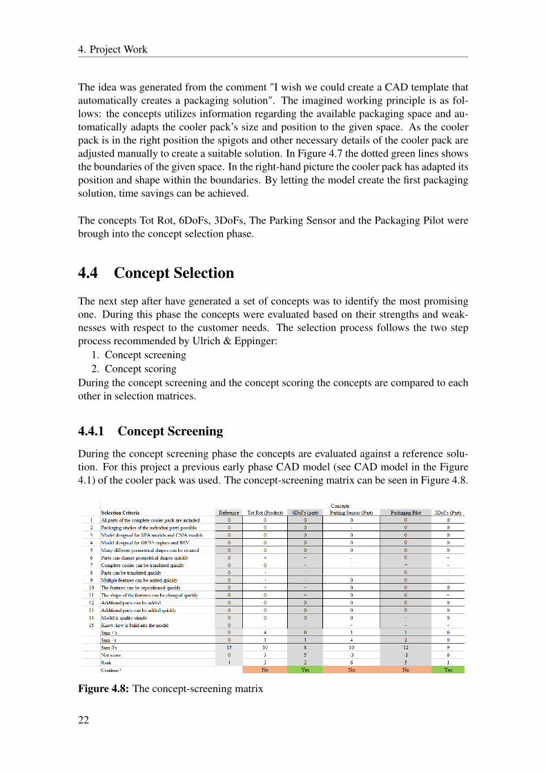
4.4.1 Concept ScreeningDuring the concept screening phase the concepts are evaluated against a reference solu-tion. For this project a previous early phase CAD model (see CAD model in the Figure4.1) of the cooler pack was used. The concept-screening matrix can be seen in Figure 4.8.
Figure 4.8: The concept-screening matrix
22

4. Project Work
The winners in the concept-screening matrix were the 3DoFs and 6DoFs concept. TheTot Rot concept was ranked as third best concept but not decided to be further developed.This was based on an external decision (Friedrich Bosch. Personal communication, 2017-04-07). The reason for not continuing the development was that the concept was a Productmodel. Product models are less suited as CAD templates compared to Part models. Fromprevious CAD templates it has been identified that the models become less stable. ThePackaging Pilot was rejected due to the low score and the concept was found hard torealize. The Packaging Sensor scored the lowest score and was rejected. Though, thefeature of informing if e.g. a part is positioned within a restriction zone was kept as ainput for the development of the winning concepts.
4.4.2 Refinement of the Winning Concepts
During this refinement stage the 6DoFs and 3DoFs concepts were created as 3D CADmodels. The knowledge acquired from the CAD advance - flexible modelling courseat Volvo Car Corporation was used to make the models flexible and stable. One mainobjective of this phase was to evaluate if a fully rotational model was more promisingthan an exclusively translatable model for the project. An initial list of all the details thatthe models should consist of was developed, see Table 4.1.
HTR LTR Condenser FanCooler Core Cooler Core Cooler Core Fan ShroudCoolant Tank x2 Coolant Tank x 2 Refrigerant tank x2 Fan BladesInlet Spigot Inlet Spigot Inlet Pipe Speed FlapsOutlet Spigot Outlet Spigot Outlet PipeBushings Upper x 2 Receiver Dryer BottleBushings Lower x 2
Table 4.1: Initial geometrical detail list
The CAD models were build up with rectangular block-shaped surfaces and cylindricalsurfaces. Simple geometries were used to benefit fast geometrical changes. An exampleof one 3D concept can be seen in Figure 4.9.
23

4. Project Work
Figure 4.9: 3D concept. One or two fans can quickly and easily be alternated with theroll-down parameter
Coding the model in the Knowledge Advisor workbench was necessary to create such aroll-down parameter as shown in Figure 4.9. Much of the work during the creation of the3D concepts was spent on coding the models. Coding knowledge acquired at ChalmersUniversity of Technology from Matlab courses was useful, but it was time demanding toadapt to the programming language in CATIA V5. To overcome numerous coding bar-riers, previous CAD templates’ codes were used as guidance during the creation of thenecessary codes. The more the coding knowledge increased, the more useful parameterscould be created. These parameters could be used to show restriction zones, e.g. therestriction zone under the receiver and dryer bottle and the NVH zones behind the fans.Know-how was built into the models by creating such parameters.
One of the main needs from the customers is that the CAD template should be easy to use.To address this need, user tests were done. These tests were done by having colleaguesfrom other departments (e.g. Propulsion System Geometry and Fuel and SCR distribu-tion) perform hypothetical packaging studies with the CAD template concepts. The inputsfrom the test participants were used to improve the user interface, which meant reorder-ing, renaming or adding parameters. For further information about the user tests, seechapter 4.7.
The fully rotational and translatable 6DoFs concept can be seen in Figure 4.10. Thedegrees of freedom of the concept’s parts and details made a big number of differentgeometrical combinations possible. Different rotation angles and positions (controlledby the parameters) of some spigots can be seen in Figure 4.10. In the right-hand picturealso the restriction zones of the fan and the receiver and dryer bottle have been activated.The 3DoFs concept was designed with the same geometrical details as 6DoFs, but therotations of the geometries were excluded.
24

4. Project Work
Figure 4.10: 3D concept of 6DoFs. Parameters for translation and rotation can be seen.
Following the creation of the two concepts as 3D models they were evaluated against eachother in the concept-scoring matrix.
4.4.3 Concept ScoringThe vital difference between the concept-screening matrix and the concept-scoring matrixis that each criteria is given a weighted number. This weighted number highlights theimportance of the criteria. In the Figure 4.11 the concept-scoring matrix can be seen.
Figure 4.11: The concept-scoring matrix.
The 6DoFs won because it had the possibility of generating a wider span of potentialgeometrical combinations. Since the possibility of generating many different geometricalshapes was a main need the 6DoFs concept was decided to be further developed in thetesting and refinement phase. In this phase the concept was presented to the the mainusers, i.e. the design engineers of the cooler pack, for additional inputs.
4.5 Testing and RefinementThe phase started with a user test together with two design engineers who had previouslyworked with cooler pack development. The response was positive regarding the flexibil-
25

4. Project Work
ity and ease of changing shapes and positions of the cooler pack. But, complaints weremade regarding the geometrical shapes of the components (B. Hansson, personal com-munication, 2017-05-03). Instead of the simple rectangular shapes of the heat exchangersmore detailed cross-sections were needed to create a useful CAD template of the coolerpack. In Figure 4.12 the cross-section in the z-direction of the 6DoFs concept and the newproposed cross-section design can be seen.
Figure 4.12: New (green) and old (blue) cross section design of the HTR.
After these user-tests the development focus of the CAD template was changed. Theinitial focus was to create a CAD template that could re-position its components and doredesigns quickly during the early packaging phases. The new development focus was tocreate a CAD template that could generate geometrical flexibility in the later packagingphases before a supplier was chosen. The main benefit of the new cross-section design isthe possibility of easily evaluating multiple supplier designs. It was stated that big timesavings could be achieved with the new cross-section design combined with parametriza-tion.Inputs were gathered regarding the number and types of geometrical details in the CADtemplate. The initial list, see Table 4.1, was extended. For example the holders keepingthe fan in the right position should be included (K. Hansson, personal communication,2017-05-03).Discussions were also held regarding the rotation of the the cooler pack and its compo-nents. The output from these discussion were that the translation in the x-,y- and thez-direction were needed and that the rotation round the y axis was beneficial to include inthe CAD template. The rotation around the y and z axes were seen as excessive. There-fore, the possibility of rotations around the y- and the z-axes were removed.
A new, final, concept was created based on the inputs from these user tests and discus-sions: the TailorMade concept. The name describes that the CAD template features aregoverned by the user inputs from the Cooling System Outer design engineers. The first3D model of the HTR according to the new cross-section design can be seen in Figure4.13.
26

4. Project Work
Figure 4.13: New HTR template design (green) and old HTR template design (blue)
The system-level design of the CAD template begun after the new user inputs had beengathered.
4.6 System-Level Design
The user inputs presented in chapter 4.5 were translated into product specifications andthe initial detail list (see Table 4.1) was extended. In this system-level design chaptereach component and its individual specifications and concept solutions are presented.The working procedure for each component has followed the same procedure;
1. the geometry was created2. the parameters were added to the parameter tree3. the coding between the geometry and the parameters was done4. user tests were carried out to evaluate if adequate solutions had been created
The cooler components are presented in the following order: the high temperature radia-tor, the low temperature radiator, the condenser, and the fan.
4.6.1 High Temperature Radiator
The choice of geometries included in this high temperature radiator model has been basedon which details of the HTR that are most space critical during the packaging study. Thespecifications list of the HTR model can be seen in Table 4.2.Cooler Core & Coolant TanksThe cooler core and coolant tanks were chosen to be designed according to the cross-section shown in Figure 4.12. The goal was to create the coolant tanks’ geometry andparameter structure so that a user could easily alternate between different supplier inputs.A parameter-set was created in which all the lengths of the cross-section could be changed(see Figure 4.14).
27

4. Project Work
Details Parameters (geometry) Parameters (Position) Restriction ZoneCooler Core YES NO NOCoolant Tank x2 YES NO YESInlet Spigot YES Y & Z NOOutlet Spigot YES Y & Z NOBushings Upper x 2 YES Y & Z NOBushings Lower x 2 NO NO NODegas Spigot YES X & Y & Z NODrainage Tap YES X & Y & Z NOFan Holders YES Y & Z NO
Table 4.2: HTR specification list
Figure 4.14: Parameter set of the coolant tank cross-section
The coolant tank needs a restriction zone because of the crimping operation when thecooler core and the coolant tanks are assembled together (B.Hansson, personal communi-cation, 2017-05-03). The crimping operation requires a clearance to the geometries on thecoolant tank. If any geometry is designed within this crimping restriction zone late designchanges might be needed. Therefore, a surface which could be activated and deactivatedfor showing the restriction zone of the coolant tank was created. In the parameter set forthe restriction zone the restriction zone surface can be activated.
Figure 4.15: Restriction zone of the coolant tank
Coolant spigots, degas spigot and drainage tapThe position of the coolant spigots needs to be flexible. The spigots themselves are not
28

4. Project Work
noticeable space requiring, but the coolant hoses that are connected to the spigots arevery space requiring. Different spigot positions are evaluated before a position is foundto which the coolant hoses can be routed. Therefore, the position of the coolant spigotsneeds to be flexible. Depending on the coolant flow the sizes of the spigots needs to beflexible (i.e. radius and length). One of the spigots can be seen in Figure 4.16. In thefigure the parameters ruling the position and the parameters ruling the size of the spigotare shown.
Figure 4.16: Illustration of different spigot geometries with parameter input.
The degas spigot and the drainage tapThe geometry, the coding and the parameter structure of the degas spigot and the drainagetap are equivalent. The spigot and the tap are designed as cylindrical surfaces which canbe translated in the y- and z-direction and with parameters for the radius and the length.To facilitate tests of positioning the degas spigot and drainage tap positions on the twocoolant tanks of the radiator, a parameter was created which enables the user to quicklymove the spigots to the opposite side. In Figure 4.17 this parameter and the two positionscan be seen.
Figure 4.17: Degas spigot on the negative y-side of the radiator and on the positive y-sideof the radiator.
29

4. Project Work
The BushingsThe bushings are necessary to include in a packaging study since they are the interface tothe surrounding frames and car body. The packaging of the cooler pack with a includedHTR is most probable to be made on a SPA platform. Therefore, the geometry of the cur-rent bushings for the SPA platform were used when creating the geometry of the bushingsin the CAD template. In the Figure 4.18 one of the lower bushings can be seen. The bush-ings can be re-positioned in the y- and in the z-direction. The bushings shall be possible tore-position in these direction because the HTR can increase and decrease its width and berisen or lowered in the z-direction. The upper bushings for the SPA platform are cylindershaped plastic parts. In the CAD template the upper bushings were therefore designed ascylinders with parameter driven length and radius. These orange colored cylinders can beseen in e.g. Figure 4.16.
Figure 4.18: Bushing seen from the left side (in the driving direction) and from a rearview.
Fan HoldersNumerous fans of previous cooler packs have been fastened to the cooler pack with fourL-shaped plastic holders. The holders were decided to be included in the model becausethey are designed as a part of the coolant tanks, and therefore needs to be positionedwithout colliding with other parts as the coolant spigots and the degas spigot. In total fourholders have been used. It was necessary to create parameters that could re-position theholders along the coolant tanks in the z-direction. In Figure 4.19 a commonly used holderdesigner and the template solution can be seen.
Figure 4.19: Production used holder and the template solution
Three different geometrical combinations of the complete HTR model can be seen inFigure 4.20.
30

4. Project Work
Figure 4.20: HTR geometries seen from the rear view in the driving direction
4.6.2 Low Temperature RadiatorThe LTR specification list can be seen in table 4.3.
Details Parameters (geometry) Parameters (Position) Restriction ZoneCooler Core YES NO NOCoolant Tank x2 YES NO YESInlet Spigot YES Y & Z NOOutlet Spigot YES Y & Z NO
Table 4.3: LTR specification list
The LTR was decided to be designed as the HTR. The difference being that the LTR wascreated with less details. The final solution can be seen in Figure 4.21.
Figure 4.21: LTR geometries seen from the rear view in the driving direction
4.6.3 The CondenserThe choice of geometries included in the condenser model was the most space requiringand relevant ones for a packaging study. The list can be seen in table 4.4.
Details Parameters (geometry) Parameters (Position) Restriction ZoneCooler Core YES NO NORefrigerant Tank x2 YES NO NOInlet Pipe YES Y & Z NOOutlet Pipe YES Y & Z NOReceiver & Dryer Bottle YES X, Y & Z + RZ YES
Table 4.4: Condenser specification list
31

4. Project Work
The Cooler Core & the Refrigerant TanksDuring the discussions described in 4.4.2 it was decided that the cross-section in the z-direction of the condenser did not have to be designed as complex as the HTR’s. Anadequate packaging cross-section was identified to be a cooler core with a rectangularcross-section, and refrigerant tanks with a circular cross-sections. The sizes of the coreand the refrigerant tanks needed to be flexible.The Inlet & the Outlet PipesThese pipes connects the condenser with the AC system. Through the pipes the refriger-ant flows that is used for cooling the air in the passenger compartment. When packagingthese pipes it is important to be able to translate them upwards and downwards in thez-direction, and translate them in the y-direction. The size of the pipes shall be flexible,depending on the refrigerant flow. With these requirements the inlet pipe and the out-let pipe were created. The design of the pipes (see Figure 4.22) were created based onprevious condenser models used in Volvo Cars’ models. The pipes can be translated inthe y- and in the z-direction. The radius of the pipes can be changed with parameters.Additionally, the pipes can be moved to the opposite side of the condenser by changingthe value in a specific parameter. A connector has to be included in the geometry of oneof the pipes. Know-how from previous projects were built into the parametrization of theconnector. To reduce the risk of damage to the connector it has to have a certain angle tothe horizontal plane. Therefore, a parameter controlling the connector angle was includedin the model. The connector and the angle alpha can be seen in Figure 4.22.
Figure 4.22: The complete condenser, the two refrigerant pipes and angle of the pressuresensor
The Receiver & Dryer BottleThe receiver and dryer bottle (RD bottle) has the function to remove harmful water fromthe AC system. The shape of the RD bottle was decided to be cylindrical. The mountingposition should be along one of the refrigerant tanks of the condenser. With these inputsan geometry of the RD was created. The final solution was a cylindrical geometry whichcould be translated in the x- and y-direction and rotated around the z-axis. The heightand the radius of the RD bottle could be changed with the model parameters. Know-howacquired during the pre-study (see chapter 4.1.1) regarding the RD bottle was applied.It was found during this study that some clearance to other components shall be left outunder the RD bottle. This is because of maintenance reasons. During the lifecycle of thecondenser, the RD bottle’s dryer bag has to be changed. The dryer bag is commonly takenout from below of the condenser. A surface (yellow surface in Figure 4.23) representingthis restriction zones was included in the model to reduce the risk of the user placing theRD bottle too close to a surrounding object. The RD bottle can be seen in Figure 4.23.
32

4. Project Work
Figure 4.23: The RD bottle
4.6.4 The FanThe specification list of the fan can be seen in Table 4.5. It was important to make the
Details Parameters (geometry) Parameters (Position) Restriction ZoneFan Shroud YES NO NOFan x 2 YES YES YESHolders x 4 YES YES NO
Table 4.5: Fan specification list
fan shroud re-sizable in the y- and in the z-direction and make the radius and position ofthe fan flexible. Additionally a parameter was included that enables the user to switchbetween one or two fans. Three possible geometrical combinations with the fan can beseen in Figure 4.24.
Figure 4.24: Different fan layouts.
The final concept of the complete CAD template is presented in chapter 5.1.
4.7 Design for User ExperienceDesign for user-experience was brought into all the concept development phases of theproject. One of the main targets of this CAD template was to make it quality-simple [8].
33

4. Project Work
A product that is quality-simple is complex, but is still easy to use. Getting the futureusers into the development process is necessary to achieve a quality-simple product. Ev-ery CAD template requires a learning curve before the user can understand the model.The purpose of creating a quality-simple CAD template was to make this learning curveas steep as possible in the beginning. Accordingly, during this project many CAD tem-plate prototypes were created in CATIA V5 and evaluated with user tests. From theseuser tests inputs for CAD template refinements were gathered. Building many prototypesand testing them with the future users is a methodology proposed by the designer DonNorman:
"People don’t know what they want. That is why it’s important that we dothis early work effectively, that we build a prototype, test it, and discoverwhat the true requirements are. And then we do it again, and again, andagain, each time, learning more and more what the concept needs to be"Quote by Don Norman [5]
Norman strongly recommends development teams to use this approach, because there isa tendency within development team to focus on the product technology itself rather thanon the context of use. To avoid a main focus on the technology, user tests were done.Before the user tests started, a short introduction to the CAD template was presented.Following the presentation the participants received a to-do list. One of these to-do listsfor the HTR can be seen in Figure 4.25.
Figure 4.25: A to-do list used during an user test
After have done the user tests the participants were asked what the liked and disliked aboutthe user-interface. For example some participant could have inputs on better naming ofthe parameters. Such a case is shown in Figure 4.26.
Figure 4.26: Inputs on naming of parameter and parameter value
Following the user tests all inputs were documented and the CAD template was continu-ously refined.
34

5Results
In this chapter the final concept of the CAD template is presented together with the vali-dation of the customer needs.
5.1 Final Thesis ConceptThe final CAD template concept can be seen in Figure 5.1.
Figure 5.1: The final CAD template concept
The geometries of the parts can be moved independently to each other. The parts ofthe cooler pack can be activated and deactivated by using the parameters. This functionenables packaging of four cylinder cooler packs (cooler pack combination in Figure 5.1)and BEV cooler packs (cooler pack combination in Figure 5.2).
Figure 5.2: BEV cooler pack
35
5. Results
In the next sub-chapter the validation of the customer needs are presented.
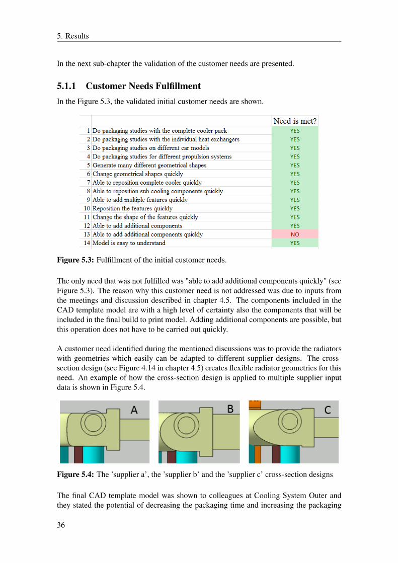
5.1.1 Customer Needs FulfillmentIn the Figure 5.3, the validated initial customer needs are shown.
Figure 5.3: Fulfillment of the initial customer needs.
The only need that was not fulfilled was "able to add additional components quickly" (seeFigure 5.3). The reason why this customer need is not addressed was due to inputs fromthe meetings and discussion described in chapter 4.5. The components included in theCAD template model are with a high level of certainty also the components that will beincluded in the final build to print model. Adding additional components are possible, butthis operation does not have to be carried out quickly.
A customer need identified during the mentioned discussions was to provide the radiatorswith geometries which easily can be adapted to different supplier designs. The cross-section design (see Figure 4.14 in chapter 4.5) creates flexible radiator geometries for thisneed. An example of how the cross-section design is applied to multiple supplier inputdata is shown in Figure 5.4.
Figure 5.4: The ’supplier a’, the ’supplier b’ and the ’supplier c’ cross-section designs
The final CAD template model was shown to colleagues at Cooling System Outer andthey stated the potential of decreasing the packaging time and increasing the packaging
36

5. Results
quality with the CAD template model.
37

5. Results
38
6Conclusion and Recommendations for
Future Work
In this chapter the conclusion of the master’s thesis and the recommendations for futurework are presented.
6.1 The Master’s Thesis Conclusion
This master’s thesis was purposed to answer the following two questions:
1. How can a CAD template be created of the front cooler pack that decreases thepackaging time?
2. How can a CAD template be created that increases the packaging quality of thefront cooler pack?
After having presented the final concept to numerous colleagues at Cooling System Outerit was stated that the CAD template was feasible for both decreasing the packaging timeand increasing the packaging quality of the cooler pack. By enabling many possible geo-metrical shapes, and by building in engineering know-how in the CAD template the twotargets could be achieved. The conclusion of the master’s thesis output is that the projecthas fulfilled its purpose. But, there are some risks that might strongly reduce the useful-ness and willingness to use the CAD template.The first risk is that model consists of a set of defined components. If the type of compo-nents in the cooler pack are extended, the CAD template might not be designed for thisor these kind of components.A second risk is the willingness to use the template. The template’s user-friendliness hascontinuously been improved during the project, but if a user does not find it user-friendlyenough, the willingness to use it will be strongly reduced. These risks can be reduced byhaving the future users reading the CAD template’s user guide.
The final conclusion is that the CAD template has to be aligned in a real packaging studyto verify if it fulfills its purpose.
39

6. Conclusion and Recommendations for Future Work
6.2 Recommendations for Future WorkThe true requirements of the CAD template were identified relatively late during theproject. Due to the restricted time, all the user inputs were not implemented in the finalconcept. By continuing the collaboration work with the design engineers from CoolingSystem Outer, a feasible CAD template of the cooler pack can be achieved.
40

7Discussion & Lessons Learned
This chapter aims to present general reflections about the project topic, the project workand the lessons learned.
7.1 Relevance of the Task and the ObjectivesVolvo Cars continuously improves their development efficiency and product quality. Re-ducing development costs and improving quality are some factors for the corporate suc-cess. The task that was done in this master’s thesis is relevant for addressing these twotargets.
7.2 MethodologyThe working methodology was inspired of the development process proposed by Ulrich& Eppinger. Ulrich & Eppinger’s development process was not fully applicable for thisproject. Their process are most suitable for physical products. Therefore, e.g. devel-opment phases connected to physical tests of the concepts or preparation phases for themanufacturing of the product was excluded in the master’s thesis methodology. Since thedevelopment process could not be applied, Ulrich & Eppinger’s work was used as a toolbox. The development phases, and most of the various development methods, that couldimprove the quality of the master’s thesis were applied. This is a recommendation for fu-ture master’s thesis projects to study all the tools provided by Ulrich & Eppinger and testthem, and use the ones that improve the development work. The main identified benefitof Ulrich & Eppinger’s tools is the continuous focus on the customers. By successfullyapplying the tools and the methods, value for the end-user is created.
7.3 Lessons LearnedCars are very complex products. They are built up by thousands of different parts. Itsnecessary to study the different systems to gain an understanding of the various workingprinciples, requirements, technical performance et cetera. During the pre-study of thisproject much literature and internal documents were studied. Studying lessons learnedfrom previous projects helped to create a good knowledge foundation about the coolingsystem. Along studying documents, meetings were organized with colleagues at VolvoCars. Asking questions regarding the cooling system to the colleagues was very helpful.Asking questions to experts at Volvo Cars is a method that I will continue to use during
41

7. Discussion & Lessons Learned
my work at Volvo Cars. I recommend to do this to future master’s thesis students. AtVolvo Cars there are many experience people with valuable car knowledge. The best ap-proach to reach this knowledge is by asking many questions and documenting the variousanswers.
The parametrization approach was seemingly new for me. Previously I have created CADmodels with the sketch-based approach. The working efficiency that a parametrized CADmodel creates has inspired me to continue to use this approach in my future developmentwork. I would recommend Product Development at Chalmers University of Technologyto extend widely the CATIA V5 education with feature knowledge.
42

Bibliography
[1] AC & Heating Connect. How Thermostatic Expansion Valves (TXV) work.Retrieved [2017-25-05] fromhttp://www.ac-heatingconnect.com/how-thermostatic-expansion-valves-txv-work/
[2] Catia "Knowledge Advisor". Retrieved [2017-05-08] fromhttp://www.catia.com.pl/tutorial/z2/knowledge_advisor.
[3] Dassault Systems "Shape Design & Styling Solutions". Retrieved [2017-05-08]fromhttps://www.3ds.com/products-services/catia/products/
v5/portfolio/domain/Shape_Design_Styling/
[4] Cengel, YA., Turner, RH., & Cimbala, JM (2008). Fundamentals of Thermal-FluidsSciences (3rd ed). New York: McGraw-Hill.
[5] Euchner, Jim (2016). Design For Use: An Interview with Don Norman Re-search Technology Management; Arlington Retrieved [2017-04-25] fromhttp://escholarship.org/uc/item/73f3p072#page-6
[6] Hardvard Business Review. Lean Knowledge Work. From the October 2011 issue.Retrieved [2017-05-25] fromhttps://hbr.org/2011/10/lean-knowledge-work
[7] Learn Engineering. Working of Refrigerator & Refrigeration Principle. Retrieved[2017-25-18] fromhttp://www.learnengineering.org/2014/04/
working-of-Refrigerator.html
[8] Mollerup, Per (2015). Simplicity a matter of design. Amsterdam: BIS Publischer.
[9] Technology Student (2013). What is market pull? Retrieved [2017-02-23] fromhttp://www.technologystudent.com/prddes1/marketpull1.
html
43

Bibliography
[10] Ulrich, K. T., & Eppinger, S. D. (2012). Product Design and Development. NewYork: McGraw-Hill Irwin.
[11] Volvo Car Corporation (2017) "Our company at a glance".Retrieved [2017-05-08] from http://www.volvocars.com/intl/about/
our-company/our-company-at-a-glance
[12] Volvo Cars (2017) "Core Values. The Volvo Way."Retrieved [2017-05-31] from http://www.volvocars.com/intl/about/
our-company/our-company-at-a-glance/core-values
44

AMission Statement
Product Description Flexible CAD model (template) of thefront cooler kit for early phase
development
Benefit Proposition 1.Enable faster changes among numerousdifferent geometrical shapes and
positions2. Increase packaging maturity during the
early phases
Key business goals 1. Reduce cooling system developmenttime
2. Increase cooling system developmentquality
Primary market Engineer performing the packaging studyof the front cooler kit
Secondary market Employees participating in packagingstudy, e.g. during packaging meeting
Assumptions 1. Usage during early developmentphases (pre FC0)
2. The cooling components in “frontcooler kit” are packaged as one unit
I

A. Mission Statement
II

BCustomer Needs List & Target
Specifications
Figure B.1: List of the identified customer needs. 5 = high imporance. 1= low importance
Figure B.2: Target specifications
III

B. Customer Needs List & Target Specifications
IV

CProject Time Table
Figure C.1: Project Time Table
V