Development and Performance Verification of a Motorized ...
14
Research Article Development and Performance Verification of a Motorized Prosthetic Leg for Stair Walking Kiwon Park , 1 Hyoung-Jong Ahn, 2 Kwang-Hee Lee, 2 and Chul-Hee Lee 2 1 Department of Mechatronics Engineering, Incheon National University, Incheon 22012, Republic of Korea 2 Department of Mechanical Engineering, Inha University, Incheon 22212, Republic of Korea Correspondence should be addressed to Chul-Hee Lee; [email protected] Received 12 April 2020; Revised 3 August 2020; Accepted 25 September 2020; Published 27 October 2020 Academic Editor: Wei Wei Copyright © 2020 Kiwon Park et al. This is an open access article distributed under the Creative Commons Attribution License, which permits unrestricted use, distribution, and reproduction in any medium, provided the original work is properly cited. The present study emphasized on the optimal design of a motorized prosthetic leg and evaluation of its performance for stair walking. Developed prosthetic leg includes two degrees of freedom on the knee and ankle joint designed using a virtual product development process for better stair walking. The DC motor system was introduced to imitate gait motion in the knee joint, and a spring system was applied at the ankle joint to create torque and flexion angle. To design better motorized prosthetic leg, unnecessary mass was eliminated via a topology optimization process under a complex walking condition in a boundary considered condition and aluminum alloy for lower limb and plastic nylon through 3D printing foot which were used. The structural safety of a developed prosthetic leg was validated via finite element analysis under a variety of walking conditions. In conclusion, the motorized prosthetic leg was optimally designed while maintaining structural safety under boundary conditions based on the human walking data, and its knee motions were synchronized with normal human gait via a PD controller. The results from this study about powered transfemoral prosthesis might help amputees in their rehabilitation process. Furthermore, this research can be applied to the area of biped robots that try to mimic human motion. 1. Introduction A prosthetic leg is a basic rehabilitation device that helps rehabilitation of limb amputees, and the number of lower- limb amputees was estimated at approximately 7 million worldwide [1]. The development of prosthetic legs for lower-limb amputees is becoming an important issue. The above-knee amputees and particularly the lower-limb ampu- tees’ face increased difficulties in natural walking when com- pared with lower-knee amputees. This is because of the absence of the knee joints that are mainly responsible (50% of the importance) for the walking mechanism. The develop- ment of prosthetic leg that can create the natural knee motion is required for above-knee amputees. The prosthetic leg can be classified as passive, variable- damping, or powered [2–4]. Prosthetic legs were traditionally classified as passive or variable-damping due to limitations of power generation and battery life. Passive and variable- damping types do not result in a natural motion in keeping with user intentions. Hence, the powered type is considered to replace the passive and variable-damping types. Powered prosthetic legs are enabled by advances in computers, robot- ics, and battery technology [5]. Powered prosthetic legs can be classified based on their method of torque generation as three linkage types or direct-drive types. Conventional three linkage types are an easy way to convert the linear motion to the rotating motion at the knee joint. However, a longer linkage is required to generate a large angle at the knee joint due to kinematics and leads to issues with the dimensions. Additionally, the center of mass shifts when the translation linkage shortens. The direct-drive type directly transfers the rotational motion of the motor to the joint. However, it requires an additional device to amplify the torque, which can increase the size and weight of the prosthesis. There have been different kinds of studies about the development of powered prosthetic leg. Some researcher used electrohydraulic actuator for making the knee motion [6]. Due to advances in motor and battery technology, the Hindawi Applied Bionics and Biomechanics Volume 2020, Article ID 8872362, 14 pages https://doi.org/10.1155/2020/8872362
Transcript of Development and Performance Verification of a Motorized ...

Research ArticleDevelopment and Performance Verification of a MotorizedProsthetic Leg for Stair Walking
Kiwon Park ,1 Hyoung-Jong Ahn,2 Kwang-Hee Lee,2 and Chul-Hee Lee 2
1Department of Mechatronics Engineering, Incheon National University, Incheon 22012, Republic of Korea2Department of Mechanical Engineering, Inha University, Incheon 22212, Republic of Korea
Correspondence should be addressed to Chul-Hee Lee; [email protected]
Received 12 April 2020; Revised 3 August 2020; Accepted 25 September 2020; Published 27 October 2020
Academic Editor: Wei Wei
Copyright © 2020 Kiwon Park et al. This is an open access article distributed under the Creative Commons Attribution License,which permits unrestricted use, distribution, and reproduction in any medium, provided the original work is properly cited.
The present study emphasized on the optimal design of a motorized prosthetic leg and evaluation of its performance for stairwalking. Developed prosthetic leg includes two degrees of freedom on the knee and ankle joint designed using a virtual productdevelopment process for better stair walking. The DC motor system was introduced to imitate gait motion in the knee joint, anda spring system was applied at the ankle joint to create torque and flexion angle. To design better motorized prosthetic leg,unnecessary mass was eliminated via a topology optimization process under a complex walking condition in a boundaryconsidered condition and aluminum alloy for lower limb and plastic nylon through 3D printing foot which were used. Thestructural safety of a developed prosthetic leg was validated via finite element analysis under a variety of walking conditions. Inconclusion, the motorized prosthetic leg was optimally designed while maintaining structural safety under boundary conditionsbased on the human walking data, and its knee motions were synchronized with normal human gait via a PD controller. Theresults from this study about powered transfemoral prosthesis might help amputees in their rehabilitation process. Furthermore,this research can be applied to the area of biped robots that try to mimic human motion.
1. Introduction
A prosthetic leg is a basic rehabilitation device that helpsrehabilitation of limb amputees, and the number of lower-limb amputees was estimated at approximately 7 millionworldwide [1]. The development of prosthetic legs forlower-limb amputees is becoming an important issue. Theabove-knee amputees and particularly the lower-limb ampu-tees’ face increased difficulties in natural walking when com-pared with lower-knee amputees. This is because of theabsence of the knee joints that are mainly responsible (50%of the importance) for the walking mechanism. The develop-ment of prosthetic leg that can create the natural knee motionis required for above-knee amputees.
The prosthetic leg can be classified as passive, variable-damping, or powered [2–4]. Prosthetic legs were traditionallyclassified as passive or variable-damping due to limitations ofpower generation and battery life. Passive and variable-damping types do not result in a natural motion in keeping
with user intentions. Hence, the powered type is consideredto replace the passive and variable-damping types. Poweredprosthetic legs are enabled by advances in computers, robot-ics, and battery technology [5]. Powered prosthetic legs canbe classified based on their method of torque generation asthree linkage types or direct-drive types. Conventional threelinkage types are an easy way to convert the linear motionto the rotating motion at the knee joint. However, a longerlinkage is required to generate a large angle at the knee jointdue to kinematics and leads to issues with the dimensions.Additionally, the center of mass shifts when the translationlinkage shortens. The direct-drive type directly transfers therotational motion of the motor to the joint. However, itrequires an additional device to amplify the torque, whichcan increase the size and weight of the prosthesis.
There have been different kinds of studies about thedevelopment of powered prosthetic leg. Some researcherused electrohydraulic actuator for making the knee motion[6]. Due to advances in motor and battery technology, the
HindawiApplied Bionics and BiomechanicsVolume 2020, Article ID 8872362, 14 pageshttps://doi.org/10.1155/2020/8872362

motor is introduced as an actuator of a prosthetic leg. Threelinkage type powered prosthetic leg was developed using amotor and ball screw system [7, 8]. As motors become morecompact and are enable to produce high torque, direct-drivetype prostheses have been developed. DC motor was used forthe drive system [9–11] or a harmonic drive and belt pulleysystem to amplify the torque applied to the knee joint [12].Studies were performed on the kinematic structure designof an active prosthetic leg with a motor system [13, 14].The extant research examined control mechanisms of kneeand ankle joints to mimic a natural human gait [15, 16].However, most previous studies focused on the kinematicwalking mechanism or control for the level walking. Only afew studies carried out for control mechanisms under stairwalking condition [9].
Most of the study of the powered prosthetic leg focusedon overground walking, but for the disabled to move freely,a prosthetics capable of overcoming various obstacles shouldbe developed. Typical walking obstacles include ramps andstairs, of which obstacles requiring greater power are stairs.In order to climb the stairs, it should be considered for var-ious dynamic loads and requires more power than whenwalking on the overground. Therefore, it is inevitablyrequired to be lightweight and an optimum structure thatis as stable as possible under limited weight conditions.Existing studies focus on control to overcome the staircase,and research on optimizing the structure itself is insuffi-cient. The purpose of this study was to perform the optimi-zation of a motorized prosthesis capable of walking onstairs.
Several major factors influence the behavior of a pros-thetic leg and include the alignment, mechanical properties,length, and the weight of the components of a prostheticleg [17]. Although the weight of the prosthesis is one of theimportant factors for performance, researches to improvethe structure of the prosthesis are rarely carried out. In orderto overcome obstacles such as stair, it is necessary to studythe optimization of the structure of prosthetic legs. Recently,studies about a prosthetic leg for walking stairs have beenactively carried out, but little research has been implementedto design optimal structures for stair walking.
This study focuses on the development of a poweredtransfemoral prosthetic leg that can imitate the human walk-ing motion and is optimized for stair walking. A structuraldesign with two degrees of freedom at the knee and anklejoint was proposed. The power system of the knee joint ismost important because the knee joint plays a major role(exceeding 50%) in the walking mechanism. In order to pro-duce a higher torque for a stair walking, a larger motor andgear set should be applied, and the prosthetic leg must be rel-atively heavy due to their weight. The prosthetic leg structurewas optimized with topology optimization to reduce itsweight. Additionally, the ankle joint consists of a spring sys-tem to obtain a driving force to shift the body. The structureof the prosthetic leg was optimally designed with topologyoptimization to minimize weight while maintaining thesafety of the structure. FE analysis was performed to verifythe safety of the structure, and unlocked prosthetic leg testwas carried out for testing the controller.
2. Design of the Motorized ProstheticLeg System
2.1. Design Torque-Generating System. A transfemoral pros-thetic leg is a rehabilitation apparatus for above-knee ampu-tees. Thus, it is necessary for a prosthetic leg to implementthe functions of the knee and ankle joints. Furthermore, itis necessary for a powered prosthetic leg to imitate themotion of each joint and to also possess dimensions similarto the body size to ensure user comfort. In this study, thewalking mechanism and lower-limb structure were analyzedto determine the dimensions and performance of a prostheticleg. A target user included a 28-year-old male with a bodysize involving a height of 176.6 cm and weight of 82 kg.
A previous study indicated that the specific weight of theshank and foot should correspond to 5.99% of the total bodymass [18]. Therefore, the weight of the prosthetic leg shouldbe less than 4.912 kg, which is set as the user’s body weight.The length of the lower knee leg is measured for design.Figure 1 shows portions of the lower knee leg segment inwhich the shank possesses a length of 37.3 cm from the kneeto the ankle, and the foot is of the length of 6.5 cm. Based on aprevious study, the highest knee torque of human gait occursduring stair descent, and the normalized value at that point isapproximately 1.3Nm/kg [19]. Given a user weight ofapproximately 82 kg, the knee joint of a prosthetic leg canproduce a torque of up to approximately 106.6Nm forfunctions similar to the human knee. Similarly, the highestplantarflexion moments of human gait occur during levelwalking, and the maximum normalized value was approxi-mately 1.55Nm/kg [19]. That is, the ankle joint could sup-port a torque of 127.1Nm.
The core of the prosthesis that can climb stairs should belight, creating a torque that is strong enough to support thehuman weight. When selecting torque, safety factor wasconsidered excessively. Since the weight difference due tothe reducer was not large compared to other parts, safetywas prioritized over weight reduction of the motor withinthe range that satisfies the weight requirement.
Two types of torque generating systems exist at the kneejoint, namely, the three linkage type and the direct-drive type.Conventional linkage types can easily convert linear motionto rotation motion, but the size cannot be reduced due tothe geometry limitations. In this study, a BLDC (brushlessDC) motor was used because the three linkage-type mecha-nism involves performance and weight limitations due tothe dimensions of the linkage structure [20]. The conceptmodel is shown in Figure 2. EC 45 BLDC motor made byMaxon (136211) was selected as the knee joint motor, givena maximum power production capacity of 250W. The torqueconstant and nominal current of the motor corresponded to0.0328Nm/A and 10.2 A, respectively. If the maximum cur-rent was assumed as the nominal current, then the maximumtorque of the motor corresponded to 0.3346Nm. Therefore, areduction gear with a gear ratio of 318.5 : 1 was used toachieve the maximum required torque of 106.6Nm for theknee joint.
During stair walking, the specific aim was to control thejoint angle along the reference motion. It was important to
2 Applied Bionics and Biomechanics

check motion stability, not to control in 0.1 degree units like aprecision mechanical system. To confirm the feasibility ofoperation of the entire lightweight prosthetic system (3Dprinting structure), the experiment was conducted to see ifthe designed motorized prosthesis can properly follow thereference motion. It has been confirmed that the error ofthe angle and delay was shown at the degree level.
The spring system was introduced to create the requiredtorque without the addition of a motor and electric devicesat the ankle joint. The plate spring was used for the anklejoint because it was advantageous in terms of space applica-tions. Additionally, FE analysis was used to determine thespring coefficient. The maximum required torque corre-sponded to 127.1Nm, and the knee flexion angle at that pointwas approximately 15°. The geometrical relationship indi-cated that the displacement of the spring δ is based on the fol-lowing equation: δ = d sin θ, in which θ = 15° and d = 35mm.That is, the value of δ was approximately 9mm. The thick-ness of the plate spring was determined by comparing theresult of the FE analysis and the theoretical displacement δat which they coincided. Figure 3 shows the proper thicknessof the plate spring calculated by FE analysis. The property ofthe spring was assumed as SAE1045, which is typically usedfor spring. This material possessed a density (ρ) of7,700 kg/m3, elastic modulus (E) of 207GPa, Poisson’s ratio(v) of 0.266, and a yield stress of 1515MPa. Finally, theproper thickness of the spring was determined, and the valuecorresponded to 0.5mm.
The design specifications are summarized in Table 1. Thedesign of the active transfemoral prosthetic leg utilizes theBLDC motor designed for the knee joint. A motor with plan-etary gear and helical bevel gear actuated the knee joint. Thespring system generated torque for the driving force from theground at the ankle joint. The knee joint was capable of 100°
of flexion at the knee. Additionally, the ankle was capable of25° of plantarflexion and 15° of dorsiflexion at the ankle.
2.2. Design Process and Topology Optimization. First, thespecifications of the knee joint were defined to satisfy thereported boundary conditions for walking on stairs basedon a previous study [19]. The major components, such asthe motor and torque amplifier, were then determined. This
was followed by designing a model and improving the modelby topology optimization to reduce weight.
Topology optimization involves a mathematical methodto obtain the optimal distribution of material for given designconditions including boundary conditions. The topologyoptimization problem was formulated in 1988 using ahomogenization method [21]. Homogenization and solidisotropic material with penalization (SIMP) are widely usedmethods to solve optimization problems. These methodsallow discrete design variables with intermediate densityvalues ranging from 0 to 1. Specifically, SIMP is an extensionof the homogenization method that has gained popularity instructural optimization because of its conceptual simplicityand ease of implementation [22].
Design variables, constraints, and an objective functionare required to define an optimization problem. The problemfor minimizing mass can be expressed as follows [23]:
Minimize: mass.
Subject to F σ xð Þð Þ ≤ 0, ∀x ∈Ω: ð1Þ
The material failure function F depends on the stressfield σðxÞ and strain field εðxÞ, which are defined with respectto an original domain Ω. The failure function is defined withthe von-Mises criterion, which is normally used as a failurecriterion. The failure function F is expressed as follows:
F σð Þ = σvσe
− 1, ð2Þ
where σe denotes the equivalent stress, which is usuallyregarded as the yield stress of the material, and σv denotesthe effective von Mises stress that is computed as follows:
σv2 = 1
2 σ11 − σ22ð Þ2 + σ22 − σ33ð Þ2 + σ33 − σ11ð Þ2� �
+ 3 σ122 + σ23
2 + σ312� �:
ð3Þ
The density approach was used for topology optimiza-tion. The standard format of a linear static topology optimi-zation problem is expressed as follows:
Minimize : m = 〠N:E:
i=1ρiΩi
Subject to F σið Þ ≤ 0
〠N:E
i=1ρiVi ≤V0
0 < ρmin ≤ ρi ≤ 1
ð4Þ
The number of elements in the design domain is denotedby N.E., and Ω represents the region occupied by a finite ele-ment. Furthermore, VO denotes the volume of the designspace, and it denotes the index of the elements. The designvariable corresponds to the bulk material density, whichcan be expressed using relative material density and materialproperties of each element in the SIMP method. The
38.0
<Unit : cm>
Thigh
Lower leg37.3
6.5
4.1 6.814.6
Figure 1: Dimensions of the lower knee leg.
3Applied Bionics and Biomechanics

elasticity tensor (E) includes the following relationship:
E ρð Þ = ρnE0, ð5Þ
where n denotes a penalization factor, and ρ denotes thedensity (0 ≤ n, 0 ≤ ρ ≤ 1) [20, 24].
The optimization process and particularly topology opti-mization converge during the process of developing an activetransfemoral prosthetic leg.
The objective of optimization involved determining theoptimized structure while ensuring structural safety underworking conditions. There are three design optimizationmethods, namely, shape optimization, size optimization,and topology optimization. Shape optimization involvesdetermining the optimum shape by adjusting the positionsof each node on the outer surface of the structure underboundary conditions. Size optimization involves a processof determining the properties of structural elements such asshell thickness, beam cross-sectional properties, springstiffness, and mass. Finally, topology optimization involvesfinding an optimized structure by utilizing internal strainenergy density distributions and removing any portion thatdoes not contribute to the structural strength. These optimi-zation processes were applied to design the structure of anactive transfemoral prosthetic leg.
Knee joint Absolute encoder
Max. torque: 106.6 Nm
Planetary gear Gear ratio 318.5:1
Pin connection
Plate spring
65 mm35 mm
360 mm
12 mm12 mm
BLDC motorTorque constant: 0.0328 Nm/A Nominal current: 10.2A Maximum torque: 0.3346 Nm
Load cell
Ankle joint
Figure 2: Concept modeling of a powered transfemoral prosthetic leg.
24 mm
0.000-1.152-2.303-3.455-4.606-5.758-6.909-8.061-9.212
-10.036Thickness = 0.5 mm
<FE analysis result>
Displacement (mm)
35 mm
<Boundary condition>
T = 127.1 Nm
Rigid
Figure 3: FE analysis to obtain the proper thickness of the plate spring at the ankle joint.
Table 1: Design objectives considering body dimensions.
Specification Value
Knee range of motion 0° to 100°
Ankle range of motion −25° to 15°
Maximum knee torque 106.6 nm
Maximum ankle torque 127.1 nm
Peak knee power 250W
Height (below knee) 438mm
Maximum total weight 4.912 kg
4 Applied Bionics and Biomechanics

Additionally, NX 9.0 was used for 3D CAD modeling.Shape optimization was implemented by Optistruct Solverof Altair Hyperworks, and Inspire of SolidThinking was usedas the solver for topology optimization. The optimizationprocess commenced with the definition of the design space.It was necessary to maximize the design space while mini-mizing the space for other components and interferencecaused by the rotating motion of joints. The nondesign space,such as connections to bearings and bolts, in which optimiza-tion is not performed, was defined. The FE model was intro-duced for optimization, and properties of the material andthe boundary conditions including external load wereapplied. The design parameters for optimization were setand included design variables, objective function, con-straints, and the minimum or maximum size of the structure.Following the preprocessing, an optimization process wasperformed to determine the optimal structure while satisfy-ing the constraints. This was followed by performing optimi-zation with iterations until the performances satisfied theobjective function. After the optimization process, the opti-mized shape was designed given the optimization results.Finally, the optimized model was verified by FE analysis.
2.3. Structural Design of Artificial Foot. A prosthetic footincludes malleability to accommodate variation in the physi-cal terrain in conjunction with rigidity to enable transmissionof the body weight with adequate stability [25]. Therefore,plastic nylon was used to develop the artificial foot becauseit possesses sufficient flexibility to absorb shocks whilesupporting the body weight. It is necessary for the artificialleg to look similar to a human foot because several amputeesdesire to be perceived as normal. Therefore, it is importantthat the shape of the artificial foot is similar to that of ahuman foot and for the size to not exceed real foot size.
A few conditions involving the peak ground reactantforce were considered to design the foot structure. Accordingto the previous study [19], the peak ground reaction forceappeared during stair descent walking with a magnitude thatcorresponded to 1.5 times the body weight of a human. Themaximum ankle moment corresponded to 1.55Nm/kg andoccurred at the end of the stance phase and was also consid-ered as a boundary condition. Additionally, the anterior/pos-terior ground reaction force was also considered as aboundary condition. Two notable points occurred at 20%and 85% of the stance phase of level walking. One of thepoints involved the heel-strike phase in which the magnitude
corresponded to 0.15 times the body weight, and the otherpoint involved the toe-off phase in which the magnitudecorresponded to 0.2 times the body weight. The peak valuesat these points were considered as a boundary condition.The medial/lateral ground reaction force is relatively smalland is therefore negligible. The boundary conditions for opti-mization were determined considering the abovementionedwalking characteristics and are shown in Figure 4. Thereare three load cases for the boundary condition, and optimi-zation was performed by simultaneously applying all threecases as each case was considered independent. The loadwas imposed on the ankle joint, and fixed boundary condi-tions were applied to the ball of the foot and heel that weredirectly in contact with the ground. The foot material corre-sponded to plastic nylon, which possessed flexibility androbustness. The material had a density (ρ) of 1,230 kg/m3,an elastic modulus (E) of 2.91GPa, a Poisson’s ratio (v) of0.41, and an yield stress of 75MPa.
Following the definition of the boundary condition andmaterials, topology optimization was performed to designthe optimal shape of the structure. Figure 5(a) shows themaximum designable space, which was maximized whileavoiding the space for other components and interferencecaused by the rotating motion of the ankle joint. The nonde-sign space where optimization was not performed wasdefined at the contact surface and joint. The design space
1205.4 N
120.54 N
(a) Heel strike
1205.4 N
160.72 N
(b) Toe off
1205.4 N
127.1 Nm
(c) Mid-stance
Figure 4: Boundary conditions for foot optimization.
(a) Design space (b) Topology optimization
(d) Manufacturing (c) 3D modeling
Figure 5: Optimization process for the foot structure.
5Applied Bionics and Biomechanics

was used for topology optimization using boundary condi-tions, as shown in Figure 4 and applying a material corre-sponding to plastic nylon. Figure 5(b) shows the topologyoptimization results. The unnecessary mass was eliminatedwhile maintaining the robustness under the boundary condi-tion. However, it was too complicated to directly manufac-ture the shape by machining, and thus, 3D printing wasused to realize the model. 3D printing is advantageous as itcan create complicated shapes. Therefore, the result of opti-mization can be applied in a very similar manner by using3D printing. Figure 5(c) shows the optimized model thatwas designed based on the topology optimization resultsand manufacturing method. Finally, the optimized foot wasmanufactured by a 3D printer and is shown in Figure 5(d).
2.4. Structural Design of the Lower Limb. It is necessary forthe lower-limb structure of a prosthetic leg to sustain thebody weight of the user and bear an approximate torque of106.6Nm for the same function as the human knee when auser’s weight corresponds to 82 kg. The body weight isassumed as the maximum ground reaction force, which cor-responds to 1205.4N. A previous study [26] indicated thatthe resultant ground reaction forces were directed towardsthe center of gravity. Therefore, the resultant force of theground reaction forces was assumed to be in the same direc-
tion as the shin. Additionally, the torque imposed on theknee joint was supported by the structure of the lower limband the gear system. Constraints were applied at the end ofthe bottom of the prosthetic leg, which was connected to anadapter and was assumed as a fixed joint. The boundary con-dition for optimization was determined considering theabovementioned load conditions and is shown in Figure 6.
It is necessary for the material of the lower-limb structureto exhibit robustness for safety and ensuring weight lightnesswith respect to user comfort. Thus, 7075 aluminum alloy wasused as the design material for the lower-limb structure. Thismaterial is usually used for prostheses and is lighter than steelalloy. This material includes a density (ρ) of 2,800 kg/m3, anelastic modulus (E) of 75GPa, a Poisson’s ratio (v) of 0.33,and a yield stress of 95MPa.
Similar to the structural design, the optimization processwas implemented to design the optimal structure by consid-ering boundary conditions. Figure 7(a) shows the maximumdesignable space for the lower-limb structure. It was neces-sary for the maximum designable space to not exceed thedimensions of a human leg and to avoid interferences withother components such as motors and gearbox. The bearingsand bolts defined the nondesign space in which optimizationwas not performed. The design space was used for topologyoptimization using boundary conditions based on Figure 8
Rigid element
Rigid
Pin joint
Pin joint
element
1205.4 N
106.6 Nm
Figure 6: Boundary conditions for lower-limb optimization.
6 Applied Bionics and Biomechanics

and an aluminum alloy. Figure 7(b) shows the topologyoptimization results. In this phase, geometrical symmetrywas considered for the balance of the prosthesis. The resultindicated that the shape of the structure did not signifi-cantly differ from that of the previous model despitechanges in the thickness and edge. Following the topologyoptimization, shape optimization was implemented to obtaina better model by determining the thickness as shown inFigure 7(c). The degree of freedom of nodes placed on theouter face of the upper structure and the inner face of the
lower structure were considered as a design variable. Theconstraints and external force were the same as the boundaryconditions for topology optimization. The objective functioninvolved minimizing the mass. The contour showed thedisplacement of the shape change versus the original model.The results indicated that it was necessary to reduce thethickness to approximately 6mm. The optimal thickness ofthe structure was determined based on the results. Finally,the advanced shape of the lower-limb structure was obtainedwhile maintaining robustness under boundary conditions.
5.900E+00
5.244E+00
4.589E+00
3.933E+00
3.278E+00
2.622E+00
1.967E+00
1.311E+00
6.555E+01
0.000E+00
Shape change (mm)
(a) Design space (b) Topology optimization (c) Shape optimization (d) 3D modeling
Figure 7: Optimization process for lower-limb optimization.
Knee jointBevel helical
gear Encoder
Load cell
Plate spring
3D printed foot
Planetary gear
BLDC motor
Figure 8: Developed active prosthetic leg system.
7Applied Bionics and Biomechanics

Figures 7(d) and 8(d) show 3D modeling and the modelmanufactured by machining, respectively.
2.5. Design of the PD Controller. An important point in thedevelopment of active transfemoral prosthetic leg involvesimplementing the motion of natural gait using a powersource. It is important to analyze human gait to determinethe walking phase and to implement the motion of theaffected side that is similar to that of the normal side. In thisstudy, a walking phase was identified through a mechanicalsensor for knee joint control, and the PD controller basedon the knee angle position was applied to actively cope withvarious walking environments.
An encoder was used to collect the walking motion dataof the knee joint to analyze the walking behavior. The mea-suring system is shown in Figure 9. The gait data of eachwalking situation were collected by walking around stairsand flat ground. The data were measured five times for eachcase. The noise was removed by filtering, and the standardgait data was determined by averaging. The data of a leveland the stair walking are shown in Figure 10, and this wasused as a trajectory to implement the walking motion.
The swing motion was implemented by entering themotion to track on the motor for tracking obtained fromFigure 10. The dynamic relationship of the walking systemis as follows [23]:
τ = k θ − θeq� �
+ b _θ, ð6Þ
where τ denotes the torque of the knee and ankle joint,and k and b denote the linear stiffness and damping coeffi-cient, respectively. Additionally, θ denotes the angle of theknee joint, and θeq denotes the equilibrium angle during thetransition between phases. A position-based PD controllerwas constructed to control the active prosthetic leg andapplied to the developed prosthesis. Based on previousstudies, the parameters were tuned using a combination offeedback from the user and from visual inspection of the jointangle, torque, and power data [27].
In the PD controller, a control loop feedback mechanismthat is commonly used in industrial control systems is usedfor control. The control system is shown in Figure 11. ThePD controller is used to mitigate the stability and overshootproblems that arise when a proportional controller is usedat a high gain by adding a term proportional to the timederivative of the error signal. The value of the damping canbe adjusted to achieve a critically damped response.
The decomposition of the joint behavior into passive seg-ments requires division of the gait cycle into modes or “finitestates” [8]. The walking phase was distinguished by the loadcell and the encoder signal. A finite state machine was con-structed as shown in Figure 12 to further divide the walkingstep into four steps. The finite state machine of the prostheticleg was based on previous studies [9, 27, 28].
Phase 1 constitutes the stance phase. If the knee wasextended over a certain angle in swing flexion, then the phaseswitched to the stance phase. The sole had contact with theground, and the load was applied to the knee joint. If the heel
strike or forefoot strike was detected through the load cellattached to the middle of the structure, then the walkingphase was changed from the prelanding phase to the stancephase.
Phase 2 constitutes the preswing phase. This phaseimmediately preceded the detachment of the sole from theground, and the load on the knee moved to the oppositeleg. The heel fell from the ground while the knee bent overa certain angle, and this was followed by changing the walk-ing phase into the preswing phase.
Phase 3 constitutes the swing flexion phase. When thesole was completely separated from the ground, the load onthe knee was completely free because the load was supportedby another side leg. When the load cell confirmed that thefoot was completely separated from the ground, the walkingphase changed from the preswing phase to the swing flexionphase.
Phase 4 constitutes the swing extension phase. The kneejoint began to naturally expand. If the direction of the angu-lar velocity of the knee joint was reversed in the swing flexionphase, then the walking phase changed into the swing exten-sion phase.
Figure 9: Measuring system of the knee motion.
00 20
𝜃eq1 𝜃eq2
𝜃eq3
𝜃eq4𝜃eq1
𝜃eq2
𝜃eq3
𝜃eq4
𝜃eq1𝜃eq2
𝜃eq3
𝜃eq4
40 60
Cycle time (%)
Level walkingStair ascentStair descent
80 100
1020304050
Deg
ree (°) 60
708090
Figure 10: Measuring result of the knee motion.
8 Applied Bionics and Biomechanics

An experimental method was used to perform coefficientadjustment of the controller to optimize the walking perfor-mance of the active prosthesis system.
3. Validation of the Developed Prosthetic Leg
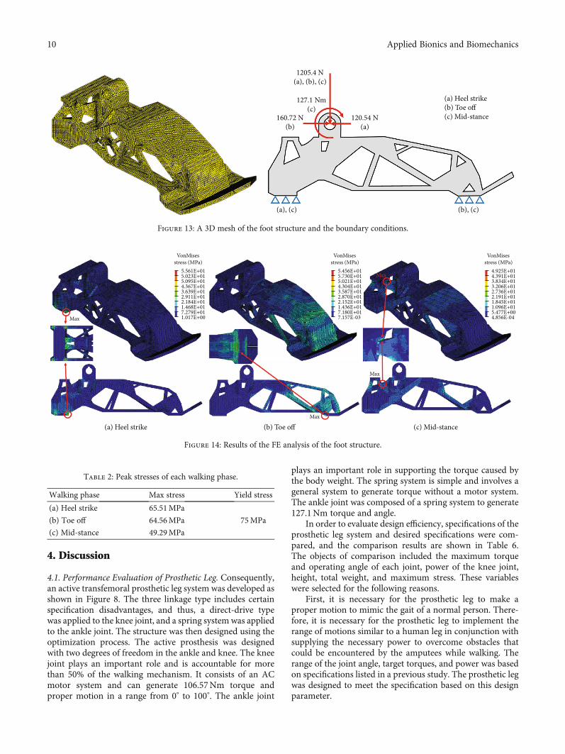
3.1. Artificial Foot Structure Analysis. It is necessary for theartificial foot to support body weight while walking. There-fore, FE analysis was performed to validate its structuralsafety. The abovementioned boundary condition wasapplied. FE analysis was performed for each of the boundaryconditions. Figure 13 shows the 3D mesh and boundary con-ditions for the analysis. The quality of the mesh was impor-tant for obtaining an accurate result. A tetra mesh was useddue to its advantages in meshing a complex solid shape.The outer surfaces and geometrical corners involved com-pact meshes for accurate analysis. The number of elementscorresponded to 141,898, and the number of nodes corre-sponded to 38,047. The model included three load cases con-sisting of heel strike, toe off, and mid-stance. The externalloads and moment of each load case acted on the center ofthe ankle joint, and constraints were applied to the ball ofthe foot and heel. All the materials were modeled as linearlyelastic, isotropic, and homogenous. Figure 14 shows theresults of the FE analysis of the foot structure. Table 2summarizes the peak stresses of each phase. The highestvon Mises stresses appeared in the heel strike phase, whichwas located at the lower surface of the heel. The maximumstress obtained in the results was compared with the tensilestrength of the materials used to check the stability withrespect to the applied load. The maximum stress corre-sponded to 65.51MPa, which was lower than the yieldstrength of the material (75MPa).
3.2. Lower-Limb Structure Analysis. In order to verify thesafety of the structure, FE analysis was performed under aboundary condition similar to that shown in Figure 6.Figure 15(a) shows the 3D mesh for the analysis. A tetramesh was used owing to its advantages in meshing a complexsolid shape. The number of elements corresponded to365,724, and the number of nodes corresponded to 84,988.
The body weight was applied to the nodes located at thecenter of the bearing holes that supported the knee shaft.The twelve bolt connections between the support and bevelgearbox were considered as rigid link components based onthe assumption that the bolts were nearly rigid bodies withlittle deformation. Fixed constraints were applied to the bolthole located at the bottom of the leg that was bolted with apyramid adaptor. All the materials were modeled as linearlyelastic, isotropic, and homogenous.
The results of the FE analysis of the lower-limb structureare shown in Figure 15(b). The maximum stress was exhib-ited in the area near the bolt hole. The value was 80.71MPalower than 95MPa, which corresponded to the yield strengthof the 7075 aluminum alloy. This implied that the structurewas safe under the load condition. Furthermore, the boltholes were simplified to a rigid element, and it displayed acharacteristic indicating a stress that exceeded the real stressbecause the rigid element acted as a load point. Therefore, itwas expected that the actual stress at the point was lower than80.71MPa.
3.3. Unlocked Prosthetic Leg Test. An experimental setup forthe unlocked prosthetic leg test was introduced to create themotion of the knee joint. The experimental setup is shownin Figure 16, and it was designed to ensure that the pros-thetic leg could move freely. The coefficient adjustment ofthe controller to optimize the walking performance of theactive prosthesis system was performed through an experi-mental method. Given the reference walking data and userfeedback, the value that could mimic the walking motion inthe most natural manner possible was selected as the coef-ficient value. Tables 3, 4, and 5 show the coefficient of thecontroller for level walking, stair ascent, and descent,respectively. The controller coefficients for each phase wereobtained through the experimental method. The equilib-rium angle θeq was selected as the peak angle of each phaseor the angle at which the ground reaction force wasimposed.
Desired input 𝜃eq(t) Kpe(t)
Motion output 𝜃O(t)
Motor system 𝜏 = 𝜅(𝜃 − 𝜃eq) + b𝜃
Error e(t)
Encoder
Controller
P
D
Σ+
+
+–de(t)dt
Kd
Figure 11: PD controller for the knee motion control.
Leg swing 𝜔k : +→ −
Toe off 𝜃k > threshold
Phase2: preswing
Heel riseF(load cell) < threshold
Heel strike (forefoot strike)F(load cell) > threshold
Phase1: stance
Phase4: swing extension
Phase3: swing flexion
Figure 12: Finite state machine.
9Applied Bionics and Biomechanics
4. Discussion
4.1. Performance Evaluation of Prosthetic Leg. Consequently,an active transfemoral prosthetic leg system was developed asshown in Figure 8. The three linkage type includes certainspecification disadvantages, and thus, a direct-drive typewas applied to the knee joint, and a spring system was appliedto the ankle joint. The structure was then designed using theoptimization process. The active prosthesis was designedwith two degrees of freedom in the ankle and knee. The kneejoint plays an important role and is accountable for morethan 50% of the walking mechanism. It consists of an ACmotor system and can generate 106.57Nm torque andproper motion in a range from 0° to 100°. The ankle joint
plays an important role in supporting the torque caused bythe body weight. The spring system is simple and involves ageneral system to generate torque without a motor system.The ankle joint was composed of a spring system to generate127.1Nm torque and angle.
In order to evaluate design efficiency, specifications of theprosthetic leg system and desired specifications were com-pared, and the comparison results are shown in Table 6.The objects of comparison included the maximum torqueand operating angle of each joint, power of the knee joint,height, total weight, and maximum stress. These variableswere selected for the following reasons.
First, it is necessary for the prosthetic leg to make aproper motion to mimic the gait of a normal person. There-fore, it is necessary for the prosthetic leg to implement therange of motions similar to a human leg in conjunction withsupplying the necessary power to overcome obstacles thatcould be encountered by the amputees while walking. Therange of the joint angle, target torques, and power was basedon specifications listed in a previous study. The prosthetic legwas designed to meet the specification based on this designparameter.
1205.4 N (a), (b), (c)
127.1 Nm (c)
160.72 N (b)
120.54 N (a)
(a), (c) (b), (c)
(a) Heel strike(b) Toe off(c) Mid-stance
Figure 13: A 3D mesh of the foot structure and the boundary conditions.
5.561E+015.023E+015.095E+014.367E+013.639E+012.911E+012.184E+011.468E+017.279E+011.017E+00
VonMises stress (MPa)
5.456E+015.730E+015.021E+014.304E+013.587E+012.870E+012.152E+011.436E+017.180E+017.157E-03
VonMises stress (MPa)
Max
(a) Heel strike (b) Toe off (c) Mid-stanceMax
Max
Max4.925E+014.391E+013.834E+013.206E+012.736E+012.191E+011.845E+011.096E+015.477E+004.856E-04
VonMises stress (MPa)
Figure 14: Results of the FE analysis of the foot structure.
Table 2: Peak stresses of each walking phase.
Walking phase Max stress Yield stress
(a) Heel strike 65.51MPa
75MPa(b) Toe off 64.56MPa
(c) Mid-stance 49.29MPa
10 Applied Bionics and Biomechanics

Second, weight is the most important factor because theuser can feel fatigue or discomfort if the prosthetic leg isheavier than their original leg. Hence, it is necessary tominimize the weight to ensure the comfort of the amputees.The developed active transfemoral prosthetic leg has a totalweight of 4,779 g, which corresponds to 97.3% of the targetweight (4,912 g) obtained by considering the user’s body size.The weight of the prosthesis is 1.150 kg for the motor,
0.920 kg for the reducer, 0.209 kg for the foot, and 2.5 kg forthe body (including cover and joint gear), totaling 4.779 kg.In addition, the experiment was conducted by supplyingpower by wire without a battery. Although the weight ofthe motor and gearbox exceeds 2 kgf, the total weight waseffectively reduced by introducing an optimization processwith respect to the structure. Similarly, it was necessary forthe total length of the prosthetic leg to be similar to the lengthof the original leg of a user. The developed prosthetic leg hada length of 444.5mm, which corresponded to 101.5% of thetarget length (438mm).
Finally, it was necessary to ensure the safety of the userwhile using the prosthetic leg. Therefore, the safety factor is
8.071E+01
7.174E+01
6.278E+01
5.382E+01
4.486E+01
3.590E+01
2.693E+01
1.797E+01
9.010E+00
4.827E-02
VonMises stress (MPa)Max
(a) 3D mesh (b) FE analysis
Figure 15: Result of the FE analysis of the lower-limb structure.
Figure 16: Experimental setup for the unlocked prosthetic leg test.
Table 3: Coefficient of controller for level walking.
Phase k (nm/deg) b (ns/m) θeq (deg)
1 6 0 25
2 4 0 13
3 0.1 0.02 59
4 0.2 0.03 9
Table 4: Coefficient of controller for stair ascent.
Phase k (nm/deg) b (ns/m) θeq (deg)
1 2 0 17
2 10 0 24
3 0.1 0.02 87
4 0.5 0.03 72
Table 5: Coefficient of controller for stair descent.
Phase k (nm/deg) b (ns/m) θeq (deg)
1 8 0 28
2 6.5 0 26
3 0.1 0.02 81
4 0.1 0.03 13
Table 6: Comparison between the desired and prosthetic legspecifications.
RequirementProsthetic legSpecifications
Knee range of motion 0° to 100° 0° to 100°
Ankle range of motion −25° to 15° −25° to 15°
Maximum knee torque 106.6 nm 106.57 nm
Maximum ankle torque 127.1 nm 127.1 nm
Peak knee power 250W 250W
Height (below-knee) 438mm 444.5mm
Maximum total weight 4.912 kg 4.779 kg
Max. stress Foot: 65.51/75MPa
Allowable stress Lower limb: 80.71/95MPa
11Applied Bionics and Biomechanics

important in designing a prosthetic leg. The yield stress ofthe used material was compared with the maximum stresspredicted by FE analysis. Plastic nylon (which is the footstructure material) has a yield strength of 75MPa. Themaximum stress of the foot structure was expected as65.51MPa, and the safety factor at this time was estimatedas 1.15. In a similar manner, the 7075 aluminum alloy,which was used to design the material of the lower-limbstructure, possesses a yield strength of 95MPa. The maxi-mum stress of the lower limb was expected as 80.71MPa,and the safety factor at this time was estimated as 1.18.The maximum stresses of each part were lower than theyield strength of each material.
The developed prosthesis was heavier than the prosthesissold on the market, although it was lighter than the dimen-sions of an actual human body. The weight of the motorand the gearbox exceeded 2 kg. It was necessary to introducea suitable motor and gearbox to reduce the weight. Hence,the implementation of the research on optimizing motorsand gearboxes will help in developing a better prosthesis.
4.2. Performance Evaluation of Controller. The comparisonbetween the desired motion and the actual drive motion withthe level walking controller obtained by the unlocked pros-thetic leg test (Figure 17(a)). The knee angle of the prosthesiswas measured while tracking the normal walking data. Theactual motion of the prosthetic knee joint exhibited a similartendency with the desired motion. The knee angle of theprosthetic leg indicated a smooth swing curve, but was rela-tively smaller than the desired angle and experienced a slight
delay. This phenomenon was due to the limitations of theexperimental system. The supplied voltage was lower thanthe nominal voltage and reduced the torque below the targettorque. It was considered that the torque estimated by theinfluence of relatively low power supply had a slight delaywhen compared to the objective data and would therebyaffect the walking speed.
Figures 17(b) and 17(c) show the comparison betweenthe desired motion and the actual drive motion with stairascent and the descent controller obtained by the unlockedprosthetic leg test. They also indicated that the objectivefunction was followed in a similar manner. However, theyexhibited slight inconsistencies. It involved a position-basedcontrol, and a delay occurred when each phase went to thenext phase. This appeared to be the cause of showing theactual knee motion follow slightly refracted curves.
The active prosthetic leg and controller exhibited behav-ior that was considerably similar to that of a normal gait. ThePD controller implemented a knee motion similar to normalwalking. The experimental result of control based on theposition data showed the feasibility of the level and stairwalking of the active prosthetic leg using the PD controller.Additionally, it allowed the framework of the walking testto mimic the motion of a normal individual.
Finally, the developed prosthetic leg was controlled by aPD controller that generated human-like walking motion,and the resulting joint kinematics were compared with acaptured human gait to verify the control performance. It isexpected that the study results with respect to the activetransfemoral prosthetic leg will help in the rehabilitation of
Phase1 Phase2 Phase3 Phase4
00 10 20 30 40
Measured joint angleDesired joint angle
50Percent of stride (%)
60 70 80 90 100
10203040
Ang
le (d
egre
e) 506070
(a) Level walking
Phase1 Phase2 Phase3 Phase4
00 10 20 30 40
Measured joint angleDesired joint angle
50Percent of stride (%)
60 70 80 90 100
20
40
60
80
Ang
le (d
egre
e)
100
(b) Stair ascent
Phase1 Phase2 Phase3 Phase4
00 10 20 30 40
Measured joint angleDesired joint angle
50Percent of stride (%)
60 70 80 90 100
20
40
60
80
Ang
le (d
egre
e)
100
(c) Stair descent
Figure 17: Comparison between the desired motion and the actual drive motion.
12 Applied Bionics and Biomechanics

amputees. Furthermore, this study can be applied to the areaof biped robots that imitate the human motion.
5. Conclusions
In this study, an active transfemoral prosthetic leg was opti-mally designed and controlled with a PD controller. Theweight of the prosthetic leg is an important factor in thedesign because it is related to user fatigue. An optimizationprocess was used for foot and lower-limb structures to obtainoptimal shapes and reduce the weight. Topology and shapeoptimization were implemented in the design. As a result,the shape of a prosthetic leg was developed without exceedingthe dimensions of the human body. The optimized footstructure was produced through 3D printing to reflect theoptimization result as much as possible. Finally, an optimizedstructure for stair walking was designed while maintainingrobustness. A PD controller based on position control wasused to control the developed prosthetic leg. The actualmotion of the prosthetic knee joint exhibited a tendency sim-ilar to the desired motion. It is expected that the results of thisstudy will aid in the rehabilitation of amputees by developingoptimal active transfemoral prosthetic legs. Furthermore, thefindings of this study can be applied to the area of bipedrobots wherein human motion is imitated.
Data Availability
The experimental and simulation data used in this study areincluded within the paper.
Conflicts of Interest
The authors declare no conflict of interest.
Acknowledgments
This work was supported by the Incheon National University(International Cooperative) research grant in 2019.
References
[1] F. Sup, H. A. Varol, J. Mitchell, T. J. Withrow, andM. Goldfarb, “Self-contained powered knee and ankle prosthe-sis: initial evaluation on a transfemoral amputee,” in 2009 IEEE11th International Conference on Rehabilitation Robotics,pp. 638–644, Kyoto, 2009.
[2] E. C. Martinez-Villalpando and H. Herr, “Agonist-antagonistactive knee prosthesis: a preliminary study in level-groundwalking,” Journal of Rehabilitation Research & Development,vol. 46, no. 3, pp. 361–373, 2009.
[3] E. Russell Esposito, J. M. Aldridge Whitehead, and J. M.Wilken, “Step-to-step transition work during level andinclined walking using passive and powered ankle–footprostheses,” Prosthetics and Orthotics International, vol. 40,no. 3, pp. 311–319, 2016.
[4] J. Realmuto, G. Klute, and S. Devasia, “Nonlinear passive cam-based springs for ankle prostheses,” Journal of Mecial Devices,vol. 9, no. 1, pp. 1–10, 2015.
[5] F. Sup, H. A. Varol, and M. Goldfarb, “Upslope walking with apowered knee and ankle prosthesis: initial results with an
amputee subject,” IEEE Transactions on Neural Systems andRehabilitation, vol. 19, no. 1, pp. 71–78, 2011.
[6] W. C. Flowers and R. W. Mann, “An electrohydraulic knee-torque controller for a prosthesis simulator,” ASME Journalof Biomechanical Engineering, vol. 99, no. 1, pp. 3–8, 1977.
[7] K. H. Lee, J. H. Chung, and C. H. Lee, “Design and optimiza-tion study of active trasfemoral prosthesis leg,” Korean Journalof Rehabilitation Welfare Engineering & Assistive Technology,vol. 7, no. 2, pp. 41–46, 2013.
[8] F. Sup, A. Bohara, and M. Goldfarb, “Design and control of apowered transfemoral prosthesis,” The International journalof robotics Research, vol. 27, no. 2, pp. 263–273, 2008.
[9] B. Lawson, H. A. Varol, A. Huff, E. Erdemir, and M. Goldfarb,“Control of stair ascent and descent with a powered transfe-moral prosthesis,” IEEE Transactions on Neural Systems andRehabilitation Engineering, vol. 21, no. 3, pp. 466–473, 2013.
[10] S. Au, M. Berniker, and H. Herr, “Powered ankle-foot prosthe-sis to assist level-ground and stair-descent gaits,” neural net-works, vol. 21, no. 4, pp. 654–666, 2008.
[11] M. Grimmer et al., “A powered prosthetic ankle joint for walk-ing and running,” Biomedical Engineering, vol. 15, no. 3,pp. 37–52, 2016.
[12] U. J. Yang and J. Y. Kim, “Mechanical design of powered pros-thetic leg and walking pattern generation based on motioncapture data,” Advanced Robotics, vol. 29, no. 16, pp. 1061–1079, 2015.
[13] R. D. Bellman, M. Holgate, and T. G. Sugar, “Design of anActive Robotic Ankle Prosthesis with Two Actuated Degreesof Freedom Using Regenerative Kinetics,” in Proceedings ofthe 2nd Biennial IEEE/RASEMBS International Conferenceon Biomedical Robotics and Biomechatronics, pp. 511–516,Scottsdale, AZ, 2008.
[14] R. Borjian, J. Lim, M. B. Khamesee, andW. Melek, “The designof an intelligent mechanical active prosthetic knee,” in Indus-trial Electronics 2008. IECON 2008. 34th Annual Conferenceof IEEE, pp. 3016–3021, Orlando, FL, 2008.
[15] K. H. Ha, H. A. Varol, and M. Goldfarb, “Volitional control ofa prosthetic knee using surface electromyography,” IEEETransactions on Biomedical Engineering, vol. 58, no. 1,pp. 144–151, 2011.
[16] M. G. Bernal-Torres, H. I. Medellin-Castillo, and J. C. Are-llano-Gonzalez, “Design and control of a new biomimetictransfemoral knee prosthesis using an echo-control scheme,”Journal of Healthcare Engineering, vol. 2018, pp. 1–17, 2018.
[17] M. Omasta, D. Paloušek, T. Návrat, and J. Rosický, “Finite ele-ment analysis for the evaluation of the structural behaviour, ofa prosthesis for trans-tibial amputees,”Medical Engineering &Physics, vol. 34, no. 1, pp. 38–45, 2012.
[18] W. H. Ho, T.-Y. Shiang, C. C. Lee, and S. Y. Cheng, “Body seg-ment parameters of young Chinese men determined withmagnetic resonance imaging,” Medicine & Science in Sports& Exercise, vol. 45, no. 9, pp. 1759–1766, 2013.
[19] R. Riener, M. Rabuffetti, and C. Frigo, “Stair ascent anddescent at different inclinations,” Gait & Posture, vol. 15,no. 1, pp. 32–44, 2002.
[20] K. H. Lee, J. H. Chung, and C. H. Lee, “Development of artifi-cial foot of active transfemoral prosthesis system using topol-ogy optimization,” in Proceedings of the World Congress onEngineering 2015, vol. 2, pp. 1257–1260, London, 2015.
[21] M. P. Bendsøe and N. Kikuchi, “Generating optimal topologiesin structural design using a homogenization method,”
13Applied Bionics and Biomechanics

Computer Methods in Applied Mechanics and Engineering,vol. 71, no. 2, pp. 197–224, 1988.
[22] Z. Luo, N. Zhang, Y. Wang, and W. Gao, “Topology optimiza-tion of structures using meshless density variable approxi-mants,” International Journal for Numerical Methods inEngineering, vol. 93, no. 4, pp. 443–464, 2012.
[23] J. T. Pereira, E. A. Fancello, and C. S. Barcellos, “Topologyoptimization of continuum structures with material failureconstraints,” Structural and Multidisciplinary Optimization,vol. 26, no. 1-2, pp. 50–66, 2004.
[24] S. H. Cha, S. W. Lee, and S. Cho, “Experimental validation oftopology design optimization,” Computational StructuralEngineering Institute of Korea, vol. 26, no. 4, pp. 241–246,2013.
[25] M. M. Saunders, E. P. Schwentker, D. B. Kay et al., “Finite ele-ment analysis as a tool for parametric prosthetic foot designand evaluation. Technique development in the solid anklecushioned heel (SACH) foot,” Computer Methods in Biome-chanics and Biomedical Engineering, vol. 6, no. 1, pp. 75–87,2003.
[26] D. Levine, J. Richards, and M. W. Whittle,Whittle's gait anal-ysis, Churchill Livingstone, 5th edition, 2012.
[27] F. Sup, H. A. Varol, J. Mitchell, T. J. Withrow, andM. Goldfarb, “Preliminary evaluations of a self-containedanthropomorphic transfemoral prosthesis,” IEEE/ASMETransactions on Mechatronics, vol. 14, no. 6, pp. 667–676,2009.
[28] W. S. Kim, S. Y. Kim, and Y. S. Lee, “Prototype development ofa DCmotor-based powered prosthesis and its control,” in 2013RESKO Technical Conference, vol. 1, pp. 201–204, Seoul, 2013.
14 Applied Bionics and Biomechanics