Development and deployment of forced controlled (sensitive ...
59
slide 1 © ZeMA gGmbH Development and deployment of forced controlled (sensitive) robot applications Robotix-Academy Roadshow 2020 Marco Schneider, M.Sc. ZeMA 10.11.2020, Saarbrücken
Transcript of Development and deployment of forced controlled (sensitive ...

slide 1© ZeMA gGmbH
Development and deployment of
forced controlled (sensitive) robot
applications
Robotix-Academy Roadshow 2020
Marco Schneider, M.Sc.
ZeMA
10.11.2020, Saarbrücken

slide 2© ZeMA gGmbH
Literature6
Conclusion5
Validation of the solution approach4
Development of a solution approach3
Fundamentals of robotics - control strategies2
Introduction and State of the art1
Agenda

slide 3© ZeMA gGmbH
Literature6
Conclusion5
Validation of the solution approach4
Development of a solution approach3
Fundamentals of robotics - control strategies2
Introduction and State of the art1
Agenda

slide 4© ZeMA gGmbH
Introduction
source: [21], [81], [82], [83], [84]
First industry robot 1954Conventional robots +
external sensors 1979Sensitive robots 2013

slide 5© ZeMA gGmbH
Definition sensitivity
DIN 1319: Change of the value of the output
variable of a measuring device in relation to the
causal change of the value of the input variable
Input variable: torque or force
Output variable: drive torque (electrical voltage
or current)
In the context of robotics:
– A robot that does not run its program purely position-
controlled, but allows a defined compliance
– This allows the robot to react in real time to the
feedback from a force sensor and thus deviate from
its programmed path and speed
source: [17], [18], [19], [21]

slide 6© ZeMA gGmbH
Market analysis sensitive robots
Rethink Baxter
Rethink
Sawyer
IRB 14000
YuMi
KUKA LBR iiwa
14 R820
Yaskawa
MOTOMAN HC 10
KUKA LBR iisy DENSO
COBOTTA
Fanuc CR-35iA
UR 10
2012 2013 2017 2018
UR 10 (e) Franka Emika
Panda
Doosan Robotics
M1013
source: [21], [22], [23], [24], [25], [26], [27]

slide 7© ZeMA gGmbH
Market analysis sensitive robots
Overview of the operating principles I
Robot
Force/
Torque-
recording
KUKA LBR
iiwa
Universal
Robots UR
10 (e)
Yaskawa
MOTOMA
N HC10
Franka
Emika
Panda
Fanuc CR
Serie
Fanuc CR-
35iA
Denso
Robotics
Cobotta
Doosan
Roborics
M1013
At the flange
In the joints
In the base
Force/torque measurement via
strain gauges Optical sensors
source: [21], [22], [23], [24], [25], [26], [27]

slide 8© ZeMA gGmbH
Market analysis sensitive robots
Overview of the operating principles II
Robot
compensating
element
Rethink Robots Sawyer
(passive)
4 by 3
(Passiv)
Active contact flange from
FerRobotics Compliant Robot
Technology GmbH
At the flange
In the joints
source: [35]
Spring
elements

slide 9© ZeMA gGmbH
Application examples of sensitive robot applications
Assembly and machining tasks
source: [29], [30], [35]

slide 10© ZeMA gGmbH
Torque and force determination based on DMS (strain gauges)
Widely used technology for the determination of
mechanical measurement parameters
Metrologically attractive: electrical signal
Wheatstone bridge circuit
R1...R4: Resistors in the bridge branches 1...4
UB: Bridge supply voltage
UM: Bridge output voltage (measurement voltage)
2 and 3: Connection points of the bridge supply voltage
1 and 4: Connection points for bridge output voltage
source: [36]
Me
ch
an
ical
ten
sio
n
Resis
tan
ce
ch
an
ge
Str
ain
gauges

slide 11© ZeMA gGmbH
KUKA LBR iiwa
Serial kinematics
7-DoF robot redundancy
Integrated torque sensors in each axis
source: [14], [21]
Robot
PropertyKUKA LBR iiwa
Number of axes 7
Payload [kg] 14
Own weight [kg] 29,9
repeat accuracy [mm] ± 0,15
Range [mm] 820
Sensitivityintegrated torque
sensors in each axis

slide 12© ZeMA gGmbH
KUKA LBR iiwa - Torque sensor system
source: [14], [21]
Torque sensor system equipped in each axis
Torque sensor
system
Torque sensor
system

slide 13© ZeMA gGmbH
Problem definition and motivation I
force controlled applications offer a high application
potential in industrial environments
Goal: Increase the accuracy of the forces applied by the
robot
force curve
FZ
[N]
Y-coordinate of the waveblock-CS

slide 14© ZeMA gGmbH
Problem definition and motivation II
In the unstressed state, the external forces and torques of
the Kuka LBR iiwa are unequal to 0
Goal: Compensation of inaccuracies
force curve of the offset
Z-coordinate of the base-CS
FZ
[N]

slide 15© ZeMA gGmbH
Literature6
Conclusion5
Validation of the solution approach4
Development of a solution approach3
Fundamentals of robotics - control strategies2
Introduction and State of the art1
Agenda

slide 16© ZeMA gGmbH
Control strategies of robots with open kinematic chain
Most important control strategies:
1. Position control
2. Impedance control
3. Force and torque control
source: [13], [51], [61], [63], [64], [67]

slide 17© ZeMA gGmbH
Dynamic model of a robot
𝜏 = 𝑀 𝑞 𝑞 + 𝐶 𝑞, 𝑞 𝑞 + 𝐺 𝑞 + 𝐽𝑇𝐹
Non-linear coupled equation of motion
Parameters:
– 𝜏: Vector of the torques generated at the joint by the drive
– 𝑀: Mass inertia matrix
– 𝐶: Matrix of Coriolis and centrifugal moments
– 𝐺: torques caused by gravity (weight moments)
– 𝐽: Jacobi-Matrix
– 𝐹: Vector of the Cartesian forces and moments acting on the end effector
– 𝑞: Vector of the joint angles
– 𝑞: Vector of the joint velocities
– 𝑞: Vector of the joint accelerations
source: [61], [64]

slide 18© ZeMA gGmbH
Impedance control
Impedance control (= indirect force control)
– The underlying model is a virtual spring
Damping system with adjustable values for
stiffness and damping
Parameters:
– 𝑤𝑑: desired position of the end effector
– 𝑹𝑑: Rotation matrix with respect to base
KS
– 𝑣𝑑: desired velocity of the end effector
– 𝑣𝑑: desired acceleration of the end effector
– 𝛼: acceleration in cartesian space
– 𝜏: Vector of the drive-torques
– 𝐹𝑒𝑥𝑡: Vector of the external forces and
torques
– 𝑞: Vector of the joint angles
– 𝑞: Vector of the joint velocities
– 𝑤𝑖𝑠𝑡: current position of the end effector
– 𝑹𝑖𝑠𝑡: Rotation matrix with respect to base
KS
– 𝑣𝑖𝑠𝑡: end effector velocity
𝑣𝑖𝑠𝑡 = ( 𝑤𝑖𝑠𝑡𝑇 𝜔𝑖𝑠𝑡
𝑇)𝑇
𝑀𝑚 𝑥 − 𝑥𝑑 + 𝐷𝑚 𝑥 − 𝑥𝑑 + 𝐾𝑚 𝑥 − 𝑥𝑑 = 𝐹𝑒𝑥𝑡
source: [51]

slide 19© ZeMA gGmbH
Impedance control I
In order to emphasize the importance of the impedance
controller of the KUKA LBR iiwa and especially the
parameterization, only the impedance-specific
parameters stiffness and damping were varied.
As the figure clearly shows, a force-controlled assembly
task is only possible under certain conditions, namely the
correct parameter identification of stiffness and damping
constants
Mass m
Damping
constant D
spring
constant c

slide 20© ZeMA gGmbH
Impedance control II
Adjust the Stiffness parameter to 200 𝑁
𝑚
Improvement of the force guided movement
0
5
10
15
20
25
30
35
40
45
50
-160 -140 -120 -100 -80 -60 -40 -20 0 20 40
Fz [
N]
y-Coordinate [mm]
Force curve
Mass m
Damping
constant D
spring
constant c

slide 21© ZeMA gGmbH
Impedance control III
Possible to change e.g. Stiffness parameter while
movement
without stop of the movement
Division into translatory and rotatory stiffness
Selection of individual degrees of freedom X, Y, Z,
A, B, C comparable elements of a pose in
space

slide 22© ZeMA gGmbH
Hybrid force/ position control I
Hybrid force and position control
Determination of the translational and rotational degrees
of freedom, which are either position or force controlled
(task dependent)
Parameters:
– 𝑆 = Selection matrix of the
force-torque controlled degrees
of freedom
– 𝑆 = Selection matrix of the
position controlled degrees of
freedom
– 𝜏 = correcting variable vector
– 𝑤 = position vector
– 𝐹 = force vectorsource: [13], [51], [63], [64], [67]

slide 23© ZeMA gGmbH
Hybrid force/ position control II
Joint anglesJo
int a
ngle
[°]
To
rqu
e [N
m]
External torques External forces
Fo
rce [N
]
Time [s] Time [s]
Time [s]

slide 24© ZeMA gGmbH
Hybrid force/ position control III
Already integrated in KUKA Sunrise

slide 25© ZeMA gGmbH
Literature6
Conclusion5
Validation of the solution approach4
Graphical User Interface (GUI)3.5
Optimization of the configuration along a defined path3.4
Design of an offset in a dynamic environment3.3
Optimization process to identify the best configuration in a pose3.2
Condition number of the Jacobian matrix or manipulability of the kinematics as optimization criterion3.1
Development of a solution approach3
Fundamentals of robotics - control strategies2
Introduction and State of the art1
Agenda

slide 26© ZeMA gGmbH
Literature6
Conclusion5
Validation of the solution approach4
Graphical User Interface (GUI)3.5
Optimization of the configuration along a defined path3.4
Design of an offset in a dynamic environment3.3
Optimization process to identify the best configuration in a pose3.2
Condition number of the Jacobian matrix or manipulability of the kinematics as optimization criterion3.1
Development of a solution approach3
Fundamentals of robotics - control strategies2
Introduction and State of the art1
Agenda

slide 27© ZeMA gGmbH
Solution approach
External forces and torques acting on the robot are
calculated
𝜏 = (𝑱𝐺)𝑇∙ 𝐹𝑒𝑥𝑡
Conditioning of the Jacobi matrix
𝜅 𝑱𝐺 ≔ 𝑱𝐺 ∙ (𝑱𝐺)−1
– Jacobi matrix 𝑱𝐺 has the dimension: 6 x 7 not invertible
– Solution: Pseudoinverse or singular value decomposition
Manipulability of the kinematics
– primarily used for redundant kinematics
– Based on determinant of Jacobian matrix not directly
calculable
– 𝜔 = det(𝑱𝐺𝑱𝐺𝑇)
source: [77], [78]

slide 28© ZeMA gGmbH
Evaluation of the kinematic performance of the robot configuration
The course of the number of conditions shows characteristic
points at the same places (joint angle 𝛿3,2) as the course of
manipulability
Group 1
Group 2
Manipulability courseConditioning course
Conditio
n n
um
ber
Manip
ula
bili
ty

slide 29© ZeMA gGmbH
Literature6
Conclusion5
Validation of the solution approach4
Graphical User Interface (GUI)3.5
Optimization of the configuration along a defined path3.4
Design of an offset in a dynamic environment3.3
Optimization process to identify the best configuration in a pose3.2
Condition number of the Jacobian matrix or manipulability of the kinematics as optimization criterion3.1
Development of a solution approach3
Fundamentals of robotics - control strategies2
Introduction and State of the art1
Agenda

slide 30© ZeMA gGmbH
Optimization process to identify the best configuration in a pose

slide 31© ZeMA gGmbH
Literature6
Conclusion5
Validation of the solution approach4
Graphical User Interface (GUI)3.5
Optimization of the configuration along a defined path3.4
Design of an offset in a dynamic environment3.3
Optimization process to identify the best configuration in a pose3.2
Condition number of the Jacobian matrix or manipulability of the kinematics as optimization criterion3.1
Development of a solution approach3
Fundamentals of robotics - control strategies2
Introduction and State of the art1
Agenda

slide 32© ZeMA gGmbH
Design of an offset in a dynamic environment
Starting point: Calculated external forces and torques of
Kuka LBR iiwa are unequal to 0 without contact
Reasons:
– Inherent inaccuracy of torque sensors
– Inaccuracy of the dynamic model of the robot
Compensation through look-up-table
Force curve offset
Z-coordinate of the base-KS [mm]
FZ
[N]

slide 33© ZeMA gGmbH
Design of an offset in a dynamic environment
Change force component of hybrid force/position
controller online
SmartServo environment
allows changing the force component during motion
(without stopping) by accessing the robot's fine
interpolator

slide 34© ZeMA gGmbH
Literature6
Conclusion5
Validation of the solution approach4
Graphical User Interface (GUI)3.5
Optimization of the configuration along a defined path3.4
Design of an offset in a dynamic environment3.3
Optimization process to identify the best configuration in a pose3.2
Condition number of the Jacobian matrix or manipulability of the kinematics as optimization criterion3.1
Development of a solution approach3
Fundamentals of robotics - control strategies2
Introduction and State of the art1
Agenda

slide 35© ZeMA gGmbH
Optimization of the configuration along a defined path
A B

slide 36© ZeMA gGmbH
Scheme of the optimization process
A B

slide 37© ZeMA gGmbH
Display of the number of conditions along a straight line as a 3D
profile
Group 1
Group 2
Condition number course
Condition number course
Conditio
n n
um
ber
Conditio
n n
um
ber
Progress of the path [%]
Progress of the path [%]

slide 38© ZeMA gGmbH
Literature6
Conclusion5
Validation of the solution approach4
Graphical User Interface (GUI)3.5
Optimization of the configuration along a defined path3.4
Design of an offset in a dynamic environment3.3
Optimization process to identify the best configuration in a pose3.2
Condition number of the Jacobian matrix or manipulability of the kinematics as optimization criterion3.1
Development of a solution approach3
Fundamentals of robotics - control strategies2
Introduction and State of the art1
Agenda

slide 39© ZeMA gGmbH
Graphical User Interface (GUI)

slide 40© ZeMA gGmbH
Literature6
Conclusion5
Validation on the use case - grinding application4.2
Validation of the optimization process along a defined path4.1
Validation of the solution approach4
Development of a solution approach3
Fundamentals of robotics - control strategies2
Introduction and State of the art1
Agenda

slide 41© ZeMA gGmbH
Literature6
Conclusion5
Validation on the use case - grinding application4.2
Validation of the optimization process along a defined path4.1
Validation of the solution approach4
Development of a solution approach3
Fundamentals of robotics - control strategies2
Introduction and State of the art1
Agenda

slide 42© ZeMA gGmbH
Validation of the solution approach
Utilization of the kinematic
redundancy of the Kuka LBR iiwa
Variation of the configuration while
maintaining the pose
Adjusting the joint angle δ3,2Good configuration Bad configuration
Good configuration Bad configuration

slide 43© ZeMA gGmbH
Literature6
Conclusion5
Validation on the use case - grinding application4.2
Validation of the optimization process along a defined path4.1
Validation of the solution approach4
Development of a solution approach3
Fundamentals of robotics - control strategies2
Introduction and State of the art1
Agenda

slide 44© ZeMA gGmbH
Optimization process 3D ceramic part
1. Tracing the contour with the prototype tool
2. Read in the point cloud of the object in MatLab
3. Optimization and identification of the best configuration
4. Implementation of an offset in a dynamic environment
5. Execution of the grinding process (deburring)
Course of the maxima of the condition number
Maxim
a o
f th
e c
onditio
n n
um
ber
alo
ng t
he p
ath

slide 45© ZeMA gGmbH
Validation of the offset in a dynamic environment
Fsoll = 15 N
Z-coordinate of the base-CS [mm]
Z-coordinate of the base-CS [mm]
Force curve after deduction of the offset
Force curve offsetForce curve incl. the offset
FZ
[N]
FZ
[N]
FZ
[N]
Z-coordinate of the base-CS [mm]

slide 46© ZeMA gGmbH
Execution of the grinding tests
Setup of the test
Prototype tool with grinding plate and grinding disc on the
flange of the KUKA LBR iiwa
Abrasion through defined contact with the component
Measurement of the burr by laser line sensor
Quantification of the abrasion
TCPz
grinding
disc
Measurement
Laser line
sensor

slide 47© ZeMA gGmbH
Execution of the grinding tests
Robot application
Programming of the robot incl. defined interaction with the
part Force control (here: 10 N)
Specification of a normal force in the direction of the z-
axis of the TCP or flange coordinate system during the
grinding process
Optimization of the configuration of the robot using the
MatLab tool
Implementation of a offset to improve the accuracy of the
determined external forces and torques
Cyclic grinding
Cartesian speed: 25 mm/s
TCPz

slide 48© ZeMA gGmbH
Execution of the grinding tests
Comparison before vs. after
Height profile of the surface of the part
Progress of the path [%]
before after difference
Heig
ht o
f th
e e
dg
e [m
m]
slide 49© ZeMA gGmbH
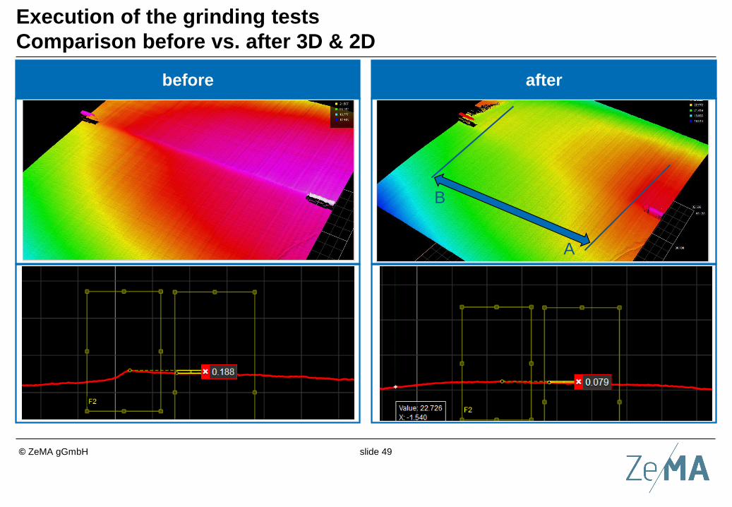
Execution of the grinding tests
Comparison before vs. after 3D & 2D
afterbefore
A
B

slide 50© ZeMA gGmbH
Literature6
Conclusion5
Validation of the solution approach4
Development of a solution approach3
Fundamentals of robotics - control strategies2
Introduction and State of the art1
Agenda

slide 51© ZeMA gGmbH
Conclusion
The use of sensitive robot systems opens up new fields of
application in the context of assembly and production
technology
Optimization procedure for a sensitive 7-DoF robot with
integrated torque sensors was presented
Increase of the accuracy of the determined external
forces and torques
Improvement of force controlled movements
Software tool in MatLab in the form of a graphical user
interface (GUI) that can be used by the operator
Proof of the added value of the developed process by
applying it to a typical assembly
Monitoring of external forces and torques possible

slide 52© ZeMA gGmbH
Outlook and future work
Process development including measuring strategy or
inspection concept of the grinding process
Tool development
Evaluation of contact forces and moments
– Possibility to evaluate the grinding process?
– conventional and unconventional approaches conceivable

slide 53© ZeMA gGmbH
Literature6
Conclusion5
Validation of the solution approach4
Development of a solution approach3
Fundamentals of robotics - control strategies2
Introduction and State of the art1
Agenda

slide 54© ZeMA gGmbH
Literature
[1] Berthold Heinrich, Petra Linke, and Michael Glöckler. Grundlagen Automatisierung:
Erfassen - Steuern - Regeln. Lehrbuch. Springer Vieweg, Wiesbaden, 3., überarbeitete
und erweiterte auflage edition, 2020.
[2] Birgit Vogel-Heuser, Thomas Bauernhansl, and Michael ten Hompel, editors.
Handbuch Industrie 4.0: Bd. 1: Produktion. Springer Reference Technik. Springer
Vieweg, Berlin, 2., erweiterte und bearbeitete auflage edition, 2017.
[3] Birgit Vogel-Heuser, Thomas Bauernhansl, and Michael ten Hompel, editors.
Handbuch Industrie 4.0: Bd. 2 : Automatisierung. Springer Reference Technik. Springer
Vieweg, Berlin, 2., erweiterte und bearbeitete auflage edition, 2017.
[4] Ifr international federation of robotics.
[5] John J. Craig. Introduction to robotics: Mechanics and control. Pearson education
international. Pearson Prentice Hall, Upper Saddle River, NJ, 3. ed., international ed.
edition, 2005.
[13] Wolfgang Weber. Industrieroboter: Methoden der Steuerung und Regelung. 4.,
aktualisierte auflage edition, 2019.

slide 55© ZeMA gGmbH
Literature
[14] Rainer Müller, Jörg Franke, Dominik Henrich, Bernd Kuhlenkötter, Annika Raatz,
and Alexander Verl. Handbuch Mensch-Roboter-Kollaboration. Hanser, München, 2019.
[15] Prof. Dr.-Ing. Rainer Müller. Kinematik, Dynamik und Anwendung in der Robotik.
Vorlesung, Universität des Saarlandes, 2020.
[17] DIN 1319. Grundlagen der messtechnik: Begriffe für messmittel, 2005.
[18] ABB Automation GmbH. Intelligente roboter durch kraft-moment-sensorik, 2014.
[19] verlag moderne industrie GmbH. Sensitive roboter unterstützen die logistik.
[21] Kuka ag: Kuka lbr iiwa, 04.06.2020.
[22] Universal Robots. Universal robots ur 10e, 04.06.2020.
[23] Franka Emika GmbH. Franka emika panda, 04.06.2020.
[24] Doosan Robotics. Doosan robotics m1013, 04.06.2020.
[25] Yaskawa Motoman Robotics. Yaskawa motoman hc 10, 04.06.2020.
[26] Denso Robotics. Denso cobotta, 04.06.2020.

slide 56© ZeMA gGmbH
Literature
[27] Fanuc. Fanuc cr-35ia, 04.06.2020.
[29] Abb ltd.
[30] Friedrich Lange, Wieland Bertleff, and Michael Suppa. Force and trajectory control of
industrial robots in stiff contact. In 2013 IEEE International Conference on Robotics and
Automation, pages 2927–2934. IEEE, 06.05.2013 - 10.05.2013.
[31] VDI 2861 - Blatt 1. Montage- und handhabungstechnik; kenngrößen für
industrieroboter: Achsbezeichnungen, 1988.
[32] Kenneth Henderson Hunt. Kinematic geometry of mechanisms, volume 7 of The
Oxford engineering science series. Oxford Univ. Pr, Oxford, reprinted in paperback with
(corrections) edition, 1990.
[35] Ferrobotics compliant robot technology gmbh.
[36] Stefan Keil. Dehnungsmessstreifen. Springer Vieweg, Wiesbaden, 2., neu
bearbeitete auflage edition, 2017.

slide 57© ZeMA gGmbH
Literature
[43] Diplom-Ingenieur Rainer Müller. Verbesserung des kinematischen und dynamischen
Bewegungsverhaltens von Handhabungsgeräten mit geschlossener Teilkette:
Parameteridentifikation, Bahnplanung und Bahnoptimierung, Verformungskompensation.
Dissertation, Rheinisch-Westfälischen Technischen Hochschule Aachen, 1996.
[51] Bruno Siciliano and Oussama Khatib. Springer Handbook of Robotics. Springer
International Publishing, Cham, 2016.
[61] Dipl.-Ing. Alexander Winkler. Ein Beitrag zur kraftbasierten Mensch-Roboter-
Interaktion. Dissertation, Technische Universität Chemnitz, 2006.
[63] Alin Albu-Schäffer. Regelung von Robotern mit elastischen Gelenken am Beispiel
der DLR-Leichtbauarme. Dissertation, Technischen Universität München, 2002.
[64] Alexander Winkler. Sensorgeführte Bewegungen stationärer Roboter. Dissertation.
[67] Kevin M. Lynch and Frank C. Park. Modern robotics: Mechanics, planning, and
control. Cambridge University Press, Cambridge and New York, NY and Port Melbourne,
2017.

slide 58© ZeMA gGmbH
Literature
[77] Peter Deuflhard and Andreas Hohmann. Numerische Mathematik: Eine
algorithmisch orientierte Einführung, volume / Peter Deuflhard ... ; 1 of De-Gruyter-
Lehrbuch. De Gruyter, Berlin, 4., überarb. und erw. aufl., [elektronische ressource]
edition, 2008.
[78] Hans Rudolf Schwarz and Norbert Köckler. Numerische Mathematik.
Vieweg+Teubner Verlag / Springer Fachmedien Wiesbaden GmbH Wiesbaden,
Wiesbaden, 8., aktualisierte auflage edition, 2011.
[80] Rainer Müller, Ali Kanso, Marco Schneider. Practically oriented investigation of
sensitive robots regarding the execution of force controlled applications. In Conference:
RACIR 2020 – Robotix-Academy Conference for Industrial Robotics.
[81] robotics.org, 16.10.2020
[82] IPR GmbH, 16.10.2020
[83] Robotiq, 16.10.2020
[84] LMI TECHNOLOGIES INC, 16.10.2020

slide 59© ZeMA gGmbH
Thank you for your attention!


![[Policy Name] · Web viewA cloud deployment using at least two different cloud deployment models. An example is using resources from a public cloud for displaying non‐sensitive](https://static.fdocuments.us/doc/165x107/5acf0ae37f8b9aca598bee4e/policy-name-viewa-cloud-deployment-using-at-least-two-different-cloud-deployment.jpg)