DEVELOPING A COMPACT BANDPASS FILTER USING A …
42
FACULTY OF ENGINEERING AND SUSTAINABLE DEVELOPMENT . DEVELOPING A COMPACT BANDPASS FILTER USING A METAMATERIAL FOR RGSM-900 Ahmad Ejaz January 14, 2013 Master’s Thesis in Electronics Master’s Program in Electronics/Telecommunications Examiner: Prof. Daniel Rönnow Supervisor: Dr. Jenny Ivarsson
Transcript of DEVELOPING A COMPACT BANDPASS FILTER USING A …
FACULTY OF ENGINEERING AND SUSTAINABLE DEVELOPMENT .
DEVELOPING A COMPACT BANDPASS FILTER
USING A METAMATERIAL FOR RGSM-900
Ahmad Ejaz
January 14, 2013
Master’s Thesis in Electronics
Master’s Program in Electronics/Telecommunications
Examiner: Prof. Daniel Rönnow
Supervisor: Dr. Jenny Ivarsson
Ahmad Ejaz DEVELOPING A COMPACT BANDPASS FILTER USING A METAMATERIAL FOR RGSM-900
i
Abstract
Metamaterials have a wide range of potential uses in areas such as optics, transmission lines,
communication and RF design. The simplest metamaterial structures are composite right/left
handed transmission line(CRLH TL)T-structures, Split-Ring Resonators (SRR) and
Complementary Split-Ring Resonators (CSRR). Through the combination of various forms of
these structures, different performances can be achieved.
In this thesis depth investigation was performed on a metamaterial transmission line that was
realized through microstrip filter using composite right/left-handed transmission line (CRLH
TL) metamaterials. The filter was designed in the band, Railways GSM-900 (915.4 MHz –
921 MHz), and then compared with the conventional filter, because designing a metamaterial
filter is simple with considerable size reduction and improved results.
In this thesis the behavior of different parameters and their impact on the filter performance is
also investigated.
Different filters were designed by using different substrates including Rogers 5880 , Rogers
3010, Arlon 25 FR, and FR4 having different dielectric constant, thickness and loss tangent to
see their impact.
Finally, a band pass filter was designed at required frequency(915.4 MHz – 921 MHz)
through EM- simulation. The simulated values are presented and show required results.
Metamaterial filters are useful in many communication applications because they have
compact size, low loss, good performance and are cost effective.

Ahmad Ejaz DEVELOPING A COMPACT BANDPASS FILTER USING A METAMATERIAL FOR RGSM-900
ii
Acknowledgements
The author would like to thank the following persons:
His supervisor Dr. Jenny Ivarsson, for guidance and assistance.
His examiner Prof. Daniel Rönnow for guidance and technical ideas to make this
project better.
Mr. Efrain Zenteno for help in the fabrication knowledge.
Ahmad Ejaz DEVELOPING A COMPACT BANDPASS FILTER USING A METAMATERIAL FOR RGSM-900
iii
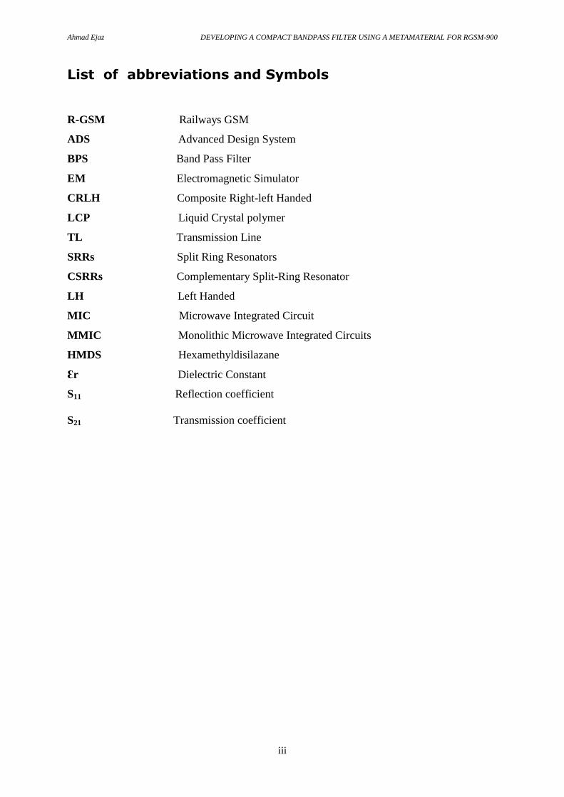
List of abbreviations and Symbols
R-GSM Railways GSM
ADS Advanced Design System
BPS Band Pass Filter
EM Electromagnetic Simulator
CRLH Composite Right-left Handed
LCP Liquid Crystal polymer
TL Transmission Line
SRRs Split Ring Resonators
CSRRs Complementary Split-Ring Resonator
LH Left Handed
MIC Microwave Integrated Circuit
MMIC Monolithic Microwave Integrated Circuits
HMDS Hexamethyldisilazane
Ɛr Dielectric Constant
S11 Reflection coefficient
S21 Transmission coefficient

Ahmad Ejaz DEVELOPING A COMPACT BANDPASS FILTER USING A METAMATERIAL FOR RGSM-900
iv
List of Figures Page
Figure 2.1 : Transmission line model of an infinitesimal length ΔZ 5
Figure 2.2 : (a) Model of right-handed line, 6
(b) Model of left-handed line, 6
(c) Model of composite right/left-handed line 6
Figure 2.3: CSRR equivalent circuit model 8
Figure 2.4: SRR equivalent circuit model 8
Figure 4.1: The layout of the microstrip bandpass filter using CRLH Transmission line and its 12
equivalent electrical circuit
Figure 4.2: (a) Schematic for 1-Cell using Rogers 3010 (for h= 5.080 mm) 15
(b) Simulation Result for 1-Cell using Rogers 3010 (for h= 5.080 mm) 16
Figure 4.3: Simulation Result for 1-Cell using Rogers 3010 (for h= 1.524 mm) 17
Figure 4.4: (a) Schematic for 1-Cell using Rogers 5880 18
(b) Simulation Result for 1-Cell using Rogers 5880 18
Figure 4.5: Simulation Result for 1-Cell using Rogers 5880(for h= 5.080 mm) 19
Figure 4.6: Simulation Result for 1-Cell using Arlon 25 FR(h=1.4732 mm) 21
Figure 4.7: Simulation Result for 1-Cell using FR4(h=1.4732 mm, tan D= 0.0009) 22
Figure 5.1: ADS generated single cell Mesh layout 25
Figure 5.2: Substrate layer by using material Rogers_RT_5880 26
Figure 5.3: Shifted EM simulation result for S21 27
Figure 5.4: Shifted EM simulation result for S11 28
Figure 5.5: Required EM simulation result for S21 28
Figure 5.6: Required EM simulation result for S11 29
Figure 5.7: ADS 3-D Preview 29
Figure 5.8: Far field visualization 30
Figure 5.9: Filter Layout for fabrication 30

Ahmad Ejaz DEVELOPING A COMPACT BANDPASS FILTER USING A METAMATERIAL FOR RGSM-900
v
List of Tables
Table Page
1 default dimensions of the CRLH TL BPF 14
2 layout dimensions of the CRLH TL BPF 25
3 Fabrication dimensions of the CRLH TL BPF 31

Ahmad Ejaz DEVELOPING A COMPACT BANDPASS FILTER USING A METAMATERIAL FOR RGSM-900
vi
Table of contents
Abstract .................................................................................................................................................... i
Acknowledgements ................................................................................................................................. ii
List of abbreviations and Symbols ....................................................................................................... iii
List of Figures ...................................................................................................................................... iv
List of Tables ........................................................................................................................................... v
Table of contents .................................................................................................................................... vi
CHAPTER 1 ............................................................................................................................................ 1
Introduction ......................................................................................................................................... 1
1.1 Background .................................................................................................................................. 1
1.2 Objective ....................................................................................................................................... 2
CHAPTER 2 ............................................................................................................................................ 3
Literature Review ................................................................................................................................ 3
2.1. Substrates ..................................................................................................................................... 3
2.1.1. Rogers .................................................................................................................................... 3
2.1.2. LCP ........................................................................................................................................ 3
2.1.3. Polyimide............................................................................................................................... 4
2.2 Right-handed and Left-handed Metamaterial Theory .................................................................. 4
2.2.1 Transmission line theory model ............................................................................................. 5
2.3. Metamaterial Structures: .............................................................................................................. 7
2.4. Flexible Metamaterials ................................................................................................................. 9
2.5. Fabrication techniques .................................................................................................................. 9
CHAPTER 3 .......................................................................................................................................... 10
Equipment and Software ................................................................................................................... 10
3.1.Simulation and Data Analysis ..................................................................................................... 10
3.1.1. Agilent ADS 2011 ............................................................................................................... 10
CHAPTER 4 .......................................................................................................................................... 11
Research Methodology and Designing the CRLH Metamaterial band pass filter ............................. 11
Ahmad Ejaz DEVELOPING A COMPACT BANDPASS FILTER USING A METAMATERIAL FOR RGSM-900
vii
4.1.Layout structure using CRLH Transmission line ........................................................................ 11
4.2. Transmission Line ...................................................................................................................... 13
4.3.Substrate Selection ...................................................................................................................... 13
4.4.Design and Simulations ............................................................................................................... 14
4.4.1.Rogers 3010 .......................................................................................................................... 14
4.4.2. Rogers 3010 with h=1.524 mm ........................................................................................... 16
4.4.3. Rogers 5880 ......................................................................................................................... 17
4.4.4. Rogers 5880 with incresed thickness .................................................................................. 19
4.4.5.Arlon 25 FR and FR4 ........................................................................................................... 20
4.5.Results & Discussion: ................................................................................................................. 22
CHAPTER 5 .......................................................................................................................................... 24
Momentum Simulation ...................................................................................................................... 24
5.1.Layout generation: ....................................................................................................................... 24
5.2.Substrate subscription: ................................................................................................................ 26
5.3.Port and Frequency Subscription: ............................................................................................... 27
5.4.Simulation results: ....................................................................................................................... 27
Discussion and Conclusions: ................................................................................................................. 32
References: ............................................................................................................................................ 33

Ahmad Ejaz DEVELOPING A COMPACT BANDPASS FILTER USING A METAMATERIAL FOR RGSM-900
1
CHAPTER 1
Introduction
1.1 Background
Metamaterials are structures that are relatively new in the scientific field. These structures
have particular behavior that is not commonly found.They exhibit negative permittivity and
permeability over small frequency ranges[2], which can result in backward propagation of
travelling waves. Due to these properties, several new applications are possible.
Metamaterials can be useful in RF,the optical world, communication, radar, environmental
remote sensing, military and medical systems, i.e. the majority of applications of today´s
microwave technology[4]. The most well known area where metamaterials are useful is for
invisibility cloaks, which is still being heavily researched, through extra polation,
metamaterial 3D cloaks could be constructed on LCP and not change resonance frequency
while contorted . This would prove useful for a real-world 3D invisibility cloak[2].
Another area in which metamaterials can prove useful is in transmission line applications.
This application includes filters, sensors, and power dividers. Most of the research is being
performed on substrates like Rogers and LCP.
Microwave filters play an important role in wireless and communication systems like satellite
and cellular mobile networks. In this type of systems some designing factors of microwave
filters are important. Compactness, steepness, low cost, light weight, small size, good
performance, low loss are important parameters that are desirable to have, to enhanced system
performance and to reduce the fabrication cost[4].
GSM (Global System for Mobile Communications), is the world´s most widely used cellular
phone technology. Different frequency bands are designed for the operation of GSM.
GSM-900 is used in most parts of the world including Europe.In Sweden GSM-900 is used
for Railways at frequency (915.4 MHz – 921 MHz) [23].
R-GSM is Railways Global system for mobile communications, its an international wireless
communications standard for railways communication and applications- A sub-system of
European Rail Traffic Management System, it is used for communication between train and
railway regulation control centres. It guarantees performance at high speeds without any

Ahmad Ejaz DEVELOPING A COMPACT BANDPASS FILTER USING A METAMATERIAL FOR RGSM-900
2
communication loss. R-GSM uses a specific frequency band (915.4 MHz – 921 MHz),
however R-GSM can operate on a number of frequencies that are being used around the world
[23].
1.2 Objective
The objective of this thesis is to develop a compact steep narrow band filter at a particular
frequency by using a suitable metamaterial structure by applying CRLH TL(Composite
right/left handed transmission lines) applicable for RGSM (Railways GSM-900).
Metamaterial filters have been constructed on different substrates, especially on Rogers and
LCP. They have shown not to change resonance frequency while being contorted at extreme
bends.
To achieve the objective, the following steps are applied:
1. Design a steep high performance compact micro strip filter for RGSM by using CRLH
TL technique.
2. Simulate and investigate frequency response of filter using an Electromagnetic
simulator software (ADS).
3. Simulation is carried by using different substrates at frequency 915.4 – 921 MHz and
optimized result is obtained .
4. Compare the metamaterial filter with a conventional filter.

Ahmad Ejaz DEVELOPING A COMPACT BANDPASS FILTER USING A METAMATERIAL FOR RGSM-900
3
CHAPTER 2
Literature Review
In this chapter, types of substrates, the basic concepts of metamaterials, Right-handed and
Left-handed material theory ,metamaterial structures, flexible metamaterials and fabrication
techniques are discussed. The most common substrates used are rigid such as Rogers
substrates.
Some basic structures of metamaterials known as SRRs (Split Ring Resonators) and CSRRs
(Complementary split ring resonators) are also discussed. Next, flexible metamaterials and
common flexible substrates are introduced.Two of these flexible substrates are Liquid Crystal
Polymer (LCP) and polyimide. Finally, common available fabrication techniques will be
overviewed.
2.1. Substrates
Metamaterial structures are designed for different frequency applications. The frequencies
may range from MHz to GHz and up to THz. With such a wide range of frequencies , special
compatible substrates must be used. The most common substrate is usually rigid since rigid
substrate fabrication techniques have been perfected for many years. Below, several types of
substrates commonly used in conjuction with metamaterials are discussed.
2.1.1. Rogers
Rogers substrates are designed for performance sensitive and high volume applications [19].
Rogers corporation fabricates laminates for different frequencies. Different Rogers substrates
are used for different applications. Rogers5880, Rogers R03010 are used in multiple
applications for metamaterials because of their frequency reliability [7] . Rogers boards are
mainly available with dielectric constant of 2.20 and 10.2 and comes in varying heights from
a manufacturer. These heights are much thicker than their flexible counterparts.
2.1.2. LCP
LCP is a fairly new thermoplastic organic material and is less common among the
metamaterial world but has some advantages over Rogers laminates. The main advantage is
flexibility and resistance to moisture absorption [18] .Flexibility proves useful in certain

Ahmad Ejaz DEVELOPING A COMPACT BANDPASS FILTER USING A METAMATERIAL FOR RGSM-900
4
scenarios such as 3-D invisibility cloak. When purchased from a manufacturer, LCP already
has either one or both sides laminated with copper foil and has a relative permittivity of 3.1
[20]. Wet and dry processes to etch through LCP are also known. Etching copper on LCP can
be treated similarly to a rigid substrate with feature sizes around 100 micrometer or smaller if
a backing wafer is used.
2.1.3. Polyimide
Polyimides are polymers composed of imide monomers. Polyimides are also less common
among the metamaterial world along with LCP. Polyimides are more costly than LCP and
operate at high frequencies reliably, normally at terahertz frequencies. Additionally,
polyimides can be deposited onto a substrate [8]. Similar to LCP, some polyimides can also
be dry etched.
2.2 Right-handed and Left-handed Metamaterial Theory
Conventional and CRLH (Composite right-left handed) materials have a characteristic in
common, because of structural restriction. Basically, the CRLH structure is smaller than a
quarter of a wave length [22], so it is possible to make an equivalent circuit using an inductor
or a capacitor.
To explain theoretically through vector positioning, it can be said that considering E
, H
and
S
vectors which follow the right-handed rule in nature ( S E H
), metamaterials follow the
left handed direction [8]. S
indicates the pointing vector perpendicular to the electric vector (
E
) and magnetic field vector ( H
). In right-handed materials, the direction of the S
vector is
given by the direction of movement of a right-handed screw when it rotates in the direction of
from electric field vector ( E
) to the magnetic field vector ( H
). But the direction of S
in left-
handed materials is in the opposite direction ( E H
) [23] . Mathematically this leads to
negative permittivity (ε) and negative permeability (μ), hence in right-handed materials group
velocity and phase velocity are in the same direction whereas in left-handed materials they are
in the opposite directions.
TL theory has long been a powerful analysis and design tool for conventional (RH) materials.
By modeling a CRLH metamaterial as an equivalent TL, TL line theory can be used to
analyze 1,2 or even 3-D CRLH metamaterials [22].

Ahmad Ejaz DEVELOPING A COMPACT BANDPASS FILTER USING A METAMATERIAL FOR RGSM-900
5
To develop a TL approach to CRLH, first the CRLH metamaterial will be represented by an
equivalent homogeneous CRLH TL to gain immediate insight into its fundamental
characteristics. Then an LC network implementation of the TL will be developed , since
homogeneous CRLH structures do not exist in nature . The LC network provides a realistic
description of the CRLH metamaterial.
2.2.1 Transmission line theory model
In electrical engineering wave propagation can be modeled by transmission line theory.
Therefore it is possible to represent both right-handed and left-handed materials by a
transmission line [11] [6]. Fig. 2.1 illustrates a general form of a transmission line model for
an infinitesimal length ΔZ.
Fig.. 2.1 : Transmission line model of an infinitesimal length ΔZ [6].
This model consists of a distributed series impedance, Z Ohms/m and a shunt admittance, Y
Siemens/m. The characteristic impedance, Z0 and the phase constant, β of a lossless
transmission line are expressed as;
0
ZZ
Y (1)
j ZY (2)
According to this concept it will be shown that a purely RH (PRH), purely LH(PLH), and
CRLH lossless transmission line can be modeled as illustrated in Fig. 2.2(a), (b), and (c)
respectively.
Ahmad Ejaz DEVELOPING A COMPACT BANDPASS FILTER USING A METAMATERIAL FOR RGSM-900
6
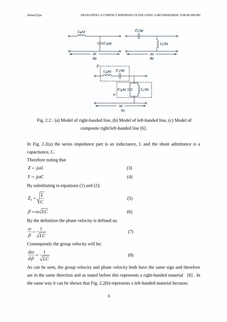
Fig. 2.2 : (a) Model of right-handed line, (b) Model of left-handed line, (c) Model of
composite right/left-handed line [6].
In Fig. 2.2(a) the series impedance part is an inductance, L and the shunt admittance is a
capacitance, C.
Therefore noting that
Z j L (3)
Y j C (4)
By substituting in equations (1) and (2);
0
LZ
C (5)
LC (6)
By the definition the phase velocity is defined as;
1
LC
(7)
Consequently the group velocity will be;
1d
d LC
(8)
As can be seen, the group velocity and phase velocity both have the same sign and therefore
are in the same direction and as stated before this represents a right-handed material [6] . In
the same way it can be shown that Fig. 2.2(b) represents a left-handed material because;

Ahmad Ejaz DEVELOPING A COMPACT BANDPASS FILTER USING A METAMATERIAL FOR RGSM-900
7
0
LZ
C (9)
1
LC
(10)
Hence the phase velocity and group velocity become
2 LC
(11)
2dLC
d
(12)
It can be seen here that the phase velocity and group velocity have different sign and therefore
point in different direction. Hence this represents a left-handed material.
In Fig. 2.2(c) the composite right/left-handed material consists of a combination of an
inductance and capacitance in both the series and shunt parts. This structure can work as a
bandpass filter. This is the desired structure which will be applied in this project to constitute
a bandpass filter.
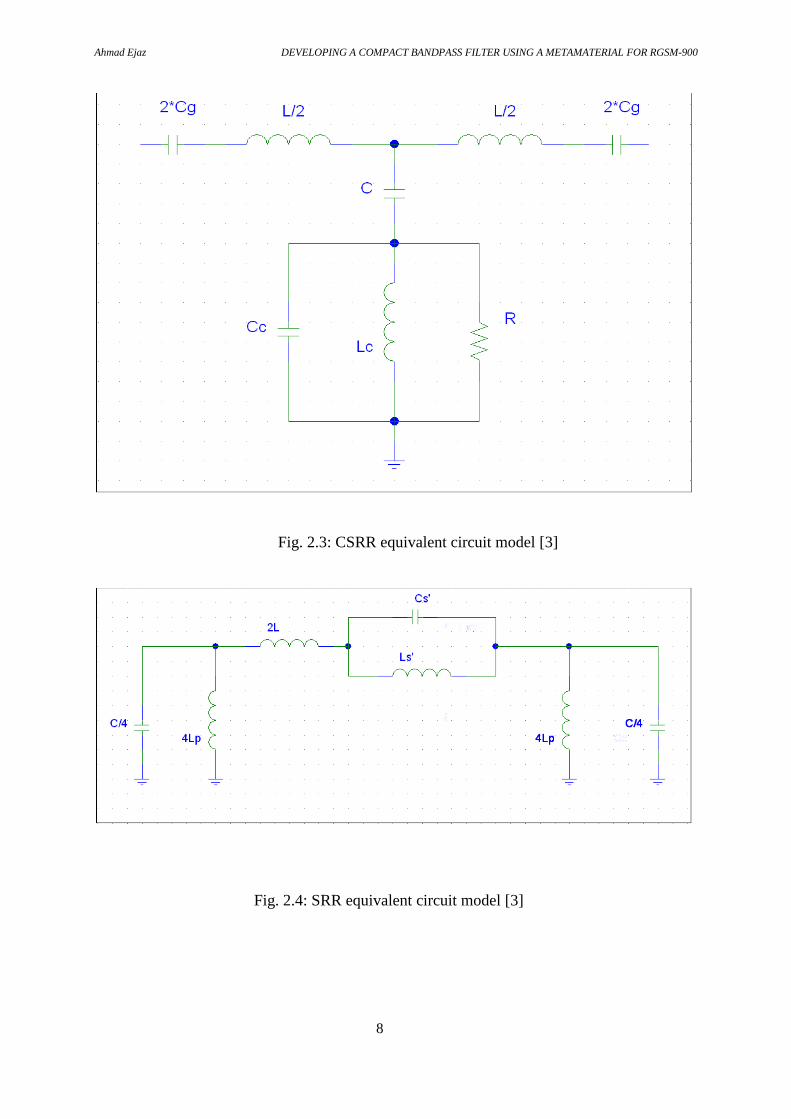
2.3. Metamaterial Structures:
There are two common basic metamaterial structures. They are the Split-Ring Resonator
(SRR) and the Complementary Split-Ring Resonator (CSRR) [3]. There are derivations of
each structure, such as edge coupled (EC-SRR) or broadside coupled (BC-SRR) . Each of
these structures can be represented by equivalent circuit models and are shown in Fig. 2.3 and
2.4 . In the figures, L and C represent the per-unit inductance and capacitance of the line. Cg
is the gap capacitance across the transmission line. Cc and Lc are the capacitance and
inductance of the rings for a CSRR. Ls’ and Cs’ represent the mutual inductance and
capacitance of a SRR.
Ahmad Ejaz DEVELOPING A COMPACT BANDPASS FILTER USING A METAMATERIAL FOR RGSM-900
8
Fig. 2.3: CSRR equivalent circuit model [3]
Fig. 2.4: SRR equivalent circuit model [3]

Ahmad Ejaz DEVELOPING A COMPACT BANDPASS FILTER USING A METAMATERIAL FOR RGSM-900
9
2.4. Flexible Metamaterials
Flexible metamaterials have been introduced onto polyimide and kapton layers. The use of
standard photolithography with a backing wafer could be used in some cases in order to
obtain smaller feature sizes of several microns [8]. In other cases, polyimide and any metals
needed for fabrication were deposited [21].
2.5. Fabrication techniques
The vast majority of published metamaterial oriented papers use standard photolithography
processes. Only a few differences occur. One of these differences is either buying prebuilt
substrates or deposition of a substrate onto a silicon wafer [8]. Another difference was the use
of a backing wafer to obtain significantly smaller feature sizes on a flexible substrate [21].
Ahmad Ejaz DEVELOPING A COMPACT BANDPASS FILTER USING A METAMATERIAL FOR RGSM-900
10
CHAPTER 3
Equipment and Software
In this chapter, laboratory software is described. Software will be presented in the order in
which it was needed in design.
3.1.Simulation and Data Analysis
The following programs were used to simulate a design, layout a design, or plot that has been
gathered.
3.1.1. Agilent ADS 2011
Agilent ADS, a commercially available electromagnetic simulation software package, proved
to be a useful tool. One part of ADS that was particularly useful was LineCalc. LineCalc
provided a calculator that could calculate impedance based off of line width, substrate
thickness, relative permittivity of substrate, copper thickness, and frequency. This was useful
for the impedance matching that was necessary for high frequency applications. The other
useful part of ADS was Momentum. Momentum provides a method-of-moments full wave
simulation. This involves performing calculations based on Maxwell’s equations for every
cell in a mesh that was defined by the user. This provided an overall more accurate simulation
than simulations with discrete components like resistors and capacitors.

Ahmad Ejaz DEVELOPING A COMPACT BANDPASS FILTER USING A METAMATERIAL FOR RGSM-900
11
CHAPTER 4
Research Methodology and Designing the CRLH Metamaterial
bandpass filter
In this chapter the methods used for designing, the layout structure and design concepts are
reviewed. Transmission line calculation and generation of layout for the EM simulation are
discussed.
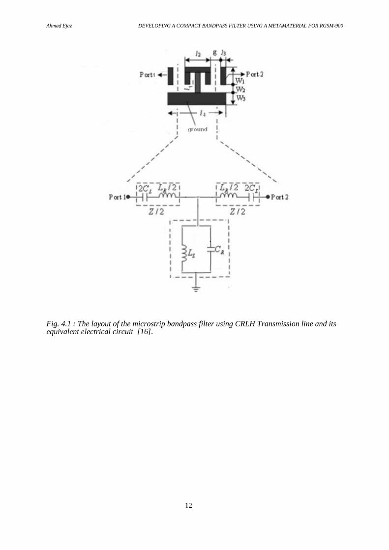
4.1.Layout structure using CRLH Transmission line
The layout of the bandpass filter using CRLH transmission line is depicted in Fig.4.1 The
filter structure will be fed after the transmission line by using the gap coupling method in
which the input and output ports are spaced symmetrically with a gap on each side. Gap
coupled microstrips give a large bandwidth as compared to conventional microstrips without
gaps. By adjusting the gap and various dimension parameters of the gap coupled microstrips,
the bandwidth can be enhanced [17].
Ahmad Ejaz DEVELOPING A COMPACT BANDPASS FILTER USING A METAMATERIAL FOR RGSM-900
12
Fig. 4.1 : The layout of the microstrip bandpass filter using CRLH Transmission line and its equivalent electrical circuit [16].

Ahmad Ejaz DEVELOPING A COMPACT BANDPASS FILTER USING A METAMATERIAL FOR RGSM-900
13
4.2. Transmission Line
Attached to Agilent ADS, there is a program called LineCalc. LineCalc was an essential tool
for designing impedance matched lines. To design a 50Ω impedance matched line, the
following parameters were changed: the relative permittivity, height of the substrate,
frequency, the thickness of the metal and dielectric constant. Once those values were inserted,
the setup was tested and the line width, W, was updated. The line width yielded was the line
width needed for the transmission line. For the designs , εr = 2.20, h = 5.080 mm, Frequency,
f = 918.2 MHz, and Z0 = 50Ω were the input parameters which yielded that the width of the
copper trace. These parameters were used for the transmission line and was added in the
layout designed for manufacturing. These optimized values are valid for any 50Ω impedence
matched line and can be used in all the simulations in ADS.
4.3.Substrate Selection
In this section the selection of a suitable substrate according to the requirements by keeping
the compactness of the filter and cheapness by means of price, is presented.
The substrates that were selected to get the required result are given below.
1) Rogers 3010 (Ɛr = 10.2 ,tan(δ) = 0.0035, h=5.080 mm)
2) Rogers 3010 (Ɛr = 10.2 , tan(δ) = 0.0035, h=1.524 mm)
3) Rogers 5880 (Ɛr = 2.20 , tan(δ) = 0.0009, h=1.524 mm)
4) Rogers 5880 (Ɛr = 2.20 , tan(δ) = 0.0009, h=5.080 mm)
5) Arlon 25 FR (Ɛr = 3.48 , tan(δ) = 0.0035, h=1.4732 mm)
6) FR4 (Ɛr = 4.6 , tan(δ) = 0.01, h=1.4732 mm)
The effect of using the different substrates with different thickness,h, loss tangent ,tan(δ), and
dielectric constant, Ɛr , is discussed in the results at the end of the chapter.

Ahmad Ejaz DEVELOPING A COMPACT BANDPASS FILTER USING A METAMATERIAL FOR RGSM-900
14
4.4.Design and Simulations
By using the above explained structure, the bandpass filter is designed and simulated to get
the acceptable required result at required frequency with good performance including a low
insertion loss in the pass band and high return loss.
For this purpose different above mentioned substrates were used.The details are given below
for each substrate used.
4.4.1.Rogers 3010
The layout of the bandpass filter using CRLH transmission line is fed by using the gap
coupling method in which the input and output ports are spaced symmetrically with a gap on
each side.
The dimensions of different parts of the metamaterial structure used in Fig. 4.1 are shown in
table 1. These dimensions can be selected as the default dimensions for starting to design
another filter, operating at different frequency.
Table 1: default dimensions of the CRLH TL BPF
Parameter Dimension
W1 2 mm
W2 2 cm
W3 5 mm
g 0.3 mm
l1 1 mm
l2 2.6 mm
l3 1 mm
l4 5 mm

Ahmad Ejaz DEVELOPING A COMPACT BANDPASS FILTER USING A METAMATERIAL FOR RGSM-900
15
This structure was simulated by means of ADS and the simulation result along with the
schematic using Rogers 3010 specifications with Ɛr = 2.20 , tan(δ) = 0.0035 and h = 5.080 is
shown in the Fig4.2 (a), (b). below.
Fig.4.2. (a) Schematic for 1-Cell using Rogers 3010 (for h= 5.080 mm).
Ahmad Ejaz DEVELOPING A COMPACT BANDPASS FILTER USING A METAMATERIAL FOR RGSM-900
16
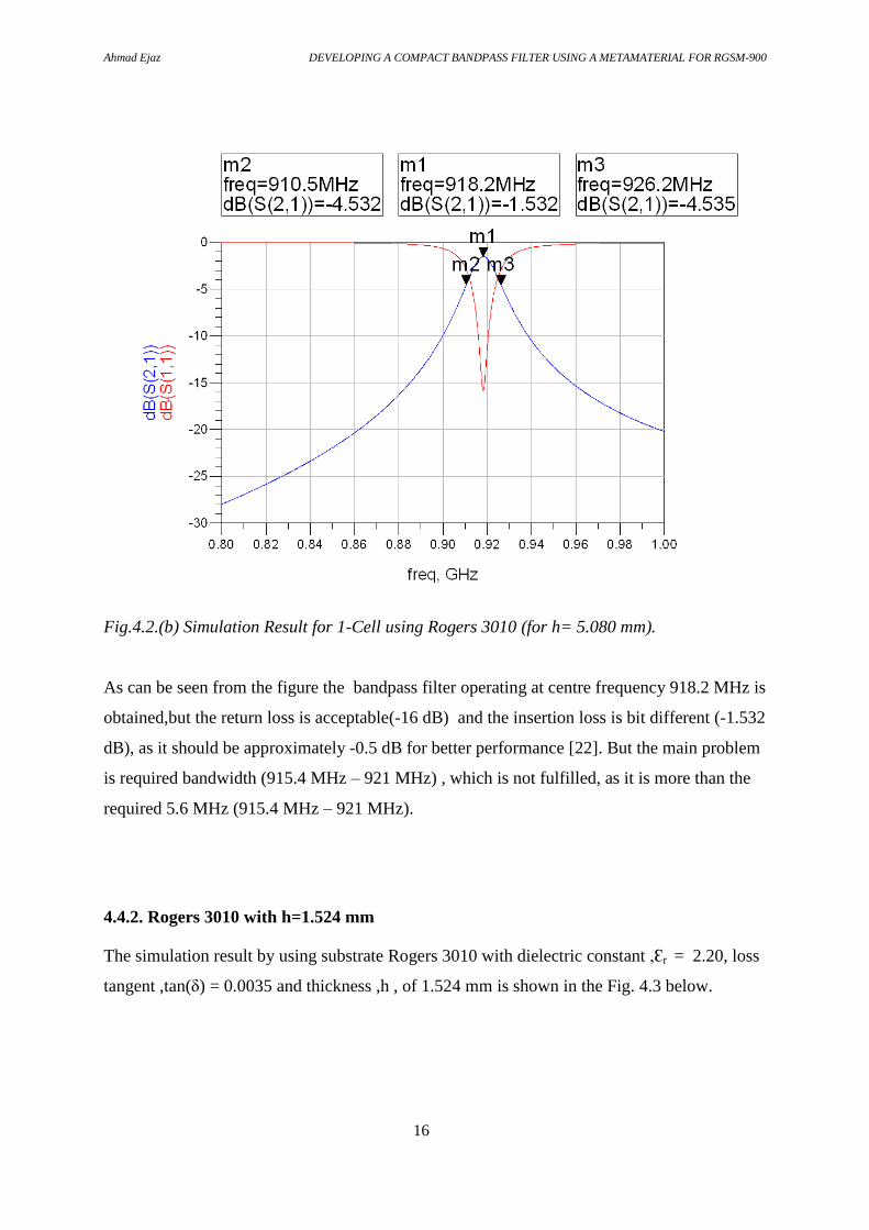
Fig.4.2.(b) Simulation Result for 1-Cell using Rogers 3010 (for h= 5.080 mm).
As can be seen from the figure the bandpass filter operating at centre frequency 918.2 MHz is
obtained,but the return loss is acceptable(-16 dB) and the insertion loss is bit different (-1.532
dB), as it should be approximately -0.5 dB for better performance [22]. But the main problem
is required bandwidth (915.4 MHz – 921 MHz) , which is not fulfilled, as it is more than the
required 5.6 MHz (915.4 MHz – 921 MHz).
4.4.2. Rogers 3010 with h=1.524 mm
The simulation result by using substrate Rogers 3010 with dielectric constant ,Ɛr = 2.20, loss
tangent ,tan(δ) = 0.0035 and thickness ,h , of 1.524 mm is shown in the Fig. 4.3 below.
Ahmad Ejaz DEVELOPING A COMPACT BANDPASS FILTER USING A METAMATERIAL FOR RGSM-900
17
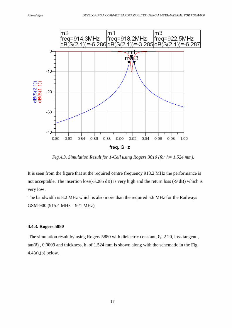
Fig.4.3. Simulation Result for 1-Cell using Rogers 3010 (for h= 1.524 mm).
It is seen from the figure that at the required centre frequency 918.2 MHz the performance is
not acceptable. The insertion loss(-3.285 dB) is very high and the return loss (-9 dB) which is
very low .
The bandwidth is 8.2 MHz which is also more than the required 5.6 MHz for the Railways
GSM-900 (915.4 MHz – 921 MHz).
4.4.3. Rogers 5880
The simulation result by using Rogers 5880 with dielectric constant, Ɛr, 2.20, loss tangent ,
tan(δ) , 0.0009 and thickness, h ,of 1.524 mm is shown along with the schematic in the Fig.
4.4(a),(b) below.

Ahmad Ejaz DEVELOPING A COMPACT BANDPASS FILTER USING A METAMATERIAL FOR RGSM-900
18
Fig. 4.4. (a) Schematic for 1-Cell using Rogers 5880.
Fig.4.4.(b) Simulation Result for 1-Cell using Rogers 5880.

Ahmad Ejaz DEVELOPING A COMPACT BANDPASS FILTER USING A METAMATERIAL FOR RGSM-900
19
As can be seen from the figure the desired bandpass filter operating at centre frequency 918.2
MHz is obtained,and the return loss is acceptable(-11 dB) along with the improvement in the
insertion loss. But the main problem is required bandwidth (915.4 MHz – 921 MHz) , which
is not fulfilled.
The bandwidth can be increased by using cascaded cells but in this way the size will be
increased along with the reduction in the performance, which is not desired.
4.4.4. Rogers 5880 with incresed thickness
Thickness of the substrate was increased from 1.524 mm to 5.080 mm. The simulation result
by using substrate Rogers 5880 with dielectric constant 2.20, loss tangent 0.0009 and
thickness of 5.080 mm, is shown in the figure 4.5 below.
Fig. 4.5 Simulation Result for 1-Cell using Rogers 5880(for h= 5.080 mm).

Ahmad Ejaz DEVELOPING A COMPACT BANDPASS FILTER USING A METAMATERIAL FOR RGSM-900
20
As can be seen from the figure the desired bandpass filter operating at centre frequency 918.2
MHz is obtained with the exact required band width 5.6 dB (915.4 MHz – 921 MHz). The
desired bandpass filter has a good performance including a low insertion loss(-0.873 dB) in
the passband and good return loss(-21 dB).
4.4.5.Arlon 25 FR and FR4
In the previous section it was found that a filter on substrate Rogers 5880 fulfills the technical
requirement, but as we aimed at creating a compact but cost effective band pass filter for
RGSM-900, the substrates Arlon 25FR and FR4 were investigated for the following reasons.
1) Arlon 25 FR is low loss material and cheaper than the Rogers substrates.
2) Standard FR4 with the same size and thickness (5.080 mm) is very cheap compared to
the Rogers substrates, but it is very lossy dielectric.
4.4.5.1. Arlon 25 FR
By using the Arlon 25 FR with the parameters Ɛr = 3.48 ,tan(δ) =0.0035, h=1.4732 mm,
the result obtained is shown in the Fig. 4.6 below.
Ahmad Ejaz DEVELOPING A COMPACT BANDPASS FILTER USING A METAMATERIAL FOR RGSM-900
21
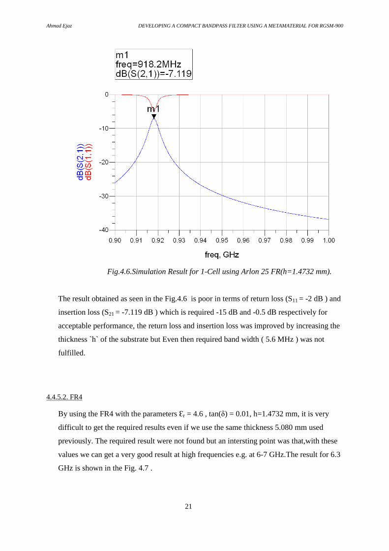
Fig.4.6.Simulation Result for 1-Cell using Arlon 25 FR(h=1.4732 mm).
The result obtained as seen in the Fig.4.6 is poor in terms of return loss (S11 = -2 dB ) and
insertion loss (S21 = -7.119 dB ) which is required -15 dB and -0.5 dB respectively for
acceptable performance, the return loss and insertion loss was improved by increasing the
thickness `h` of the substrate but Even then required band width ( 5.6 MHz ) was not
fulfilled.
4.4.5.2. FR4
By using the FR4 with the parameters Ɛr = 4.6 , tan(δ) = 0.01, h=1.4732 mm, it is very
difficult to get the required results even if we use the same thickness 5.080 mm used
previously. The required result were not found but an intersting point was that,with these
values we can get a very good result at high frequencies e.g. at 6-7 GHz.The result for 6.3
GHz is shown in the Fig. 4.7 .

Ahmad Ejaz DEVELOPING A COMPACT BANDPASS FILTER USING A METAMATERIAL FOR RGSM-900
22
Fig.4.7.Simulation Result for 1-Cell using FR4(h=1.4732 mm, tan D= 0.0009).
4.5.Results & Discussion:
The results of the simulations are summarized here.
1) The required filter specifications are obtained by using the Rogers 5880 substrate with
dielectric constant ( Ɛr = 2.20 ), loss tangent ( tan(δ) = 0.0009 ) and thickness `h` of
5.080 mm.
2) By using different substrates with different parameters, the behaviour of these
parameters including tan(δ) (loss tangent), Ɛr (Dielectric constant), and `h´ (laminates
thickness) was observed as follows.
i) A change in “tan(δ)” changes the value of S11 and S21. The smaller the value of
tan(δ) the better will be the result. The higher the value of tan(δ) the poorer the
result in terms of S11 and S21.

Ahmad Ejaz DEVELOPING A COMPACT BANDPASS FILTER USING A METAMATERIAL FOR RGSM-900
23
ii) A change in “Ɛr” makes shift in the frequency. A smaller value of , Ɛr ,shifts
the centre frequency (918.2 MHz) to higher value and higher value of, Ɛr ,shifts
the centre frequency backwards, if the stublengths are kept constant.
iii) The substrate thickness “h” is the most important parameter for the
performance. By increasing the thickness we can get improved results with low
insertion loss and high return loss. It can be said that laminates thickness and
size are the most important parameters to make the filter cost effective.

Ahmad Ejaz DEVELOPING A COMPACT BANDPASS FILTER USING A METAMATERIAL FOR RGSM-900
24
CHAPTER 5
Momentum Simulation
Momentum simulation (EM simulation) were carried out in order to generate the layout for
the chosen structure, as obtained in the previous chapter.
Since RF component designs are becoming more compact , proximity effects between
components are becoming more pronounced and have significantly more impact on the
performance.For this reason,EM simulations are required and included in the overall design
process.
EM simulations benefit in efficient meshing, adaptive frequency sampling which reduces
simulation time.The EM simulator is also able to simulate complex EM effects including skin
effects, substrate effects, thick metals and multiple dielectrics.
The steps involved in this chapter include, generation of layout, allocation of substrate
layer,allocation of conductor layer, fixing of ports, subscription of frequency plan, simulation
of generated layout and confirmation of the required performance in terms of return loss and
insertion loss.
5.1.Layout generation:
The required results were obtained by using Rogers 5880 substrate( h= 5.080 mm),which is
chosen for the layout. The layout is generated using EM simulation and is shown in Fig 5.1.
Ahmad Ejaz DEVELOPING A COMPACT BANDPASS FILTER USING A METAMATERIAL FOR RGSM-900
25
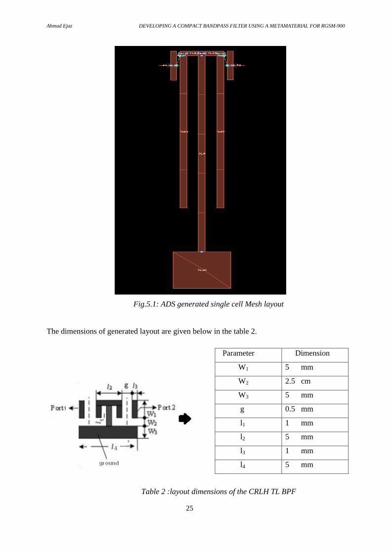
Fig.5.1: ADS generated single cell Mesh layout
The dimensions of generated layout are given below in the table 2.
Table 2 :layout dimensions of the CRLH TL BPF
Parameter Dimension
W1 5 mm
W2 2.5 cm
W3 5 mm
g 0.5 mm
l1 1 mm
l2 5 mm
l3 1 mm
l4 5 mm
Ahmad Ejaz DEVELOPING A COMPACT BANDPASS FILTER USING A METAMATERIAL FOR RGSM-900
26
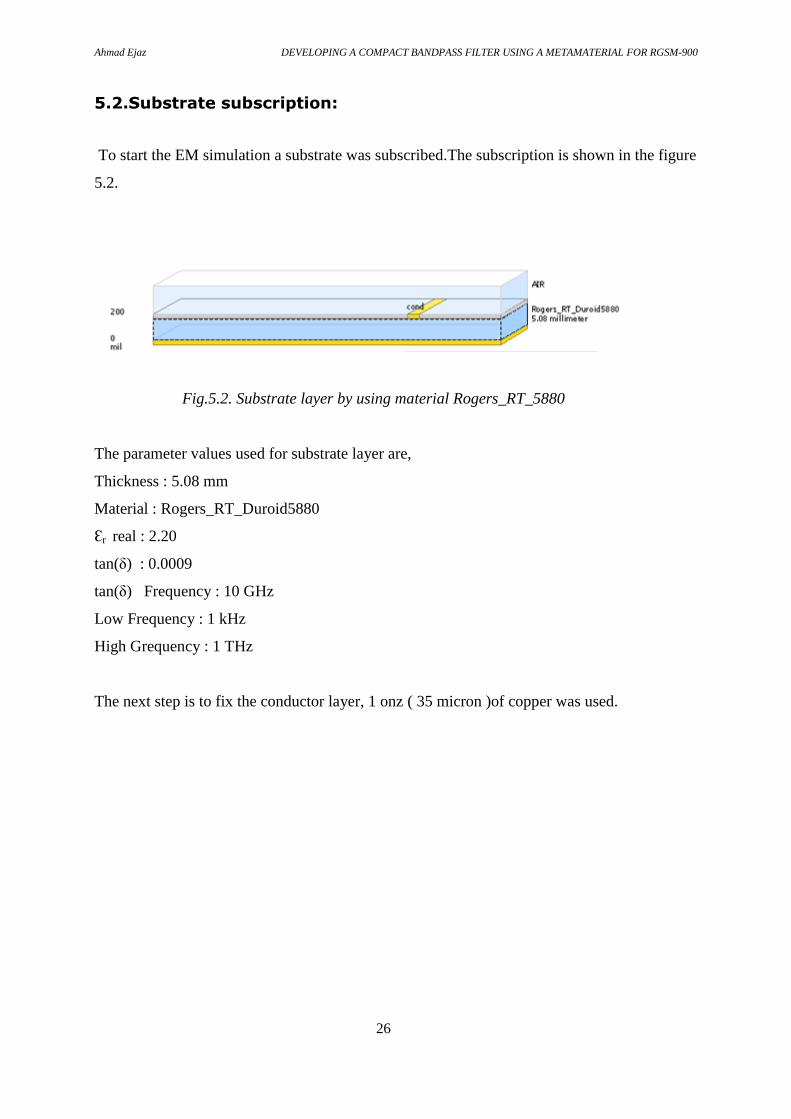
5.2.Substrate subscription:
To start the EM simulation a substrate was subscribed.The subscription is shown in the figure
5.2.
Fig.5.2. Substrate layer by using material Rogers_RT_5880
The parameter values used for substrate layer are,
Thickness : 5.08 mm
Material : Rogers_RT_Duroid5880
Ɛr real : 2.20
tan(δ) : 0.0009
tan(δ) Frequency : 10 GHz
Low Frequency : 1 kHz
High Grequency : 1 THz
The next step is to fix the conductor layer, 1 onz ( 35 micron )of copper was used.

Ahmad Ejaz DEVELOPING A COMPACT BANDPASS FILTER USING A METAMATERIAL FOR RGSM-900
27
5.3.Port and Frequency Subscription:
To proceed further the input and output ports were fixed. By default these get converted to 50
ohms ports.
Now frequency plan was selected for the range 0 – 2 GHz to get the simulation result at
desired RGSM frequency.
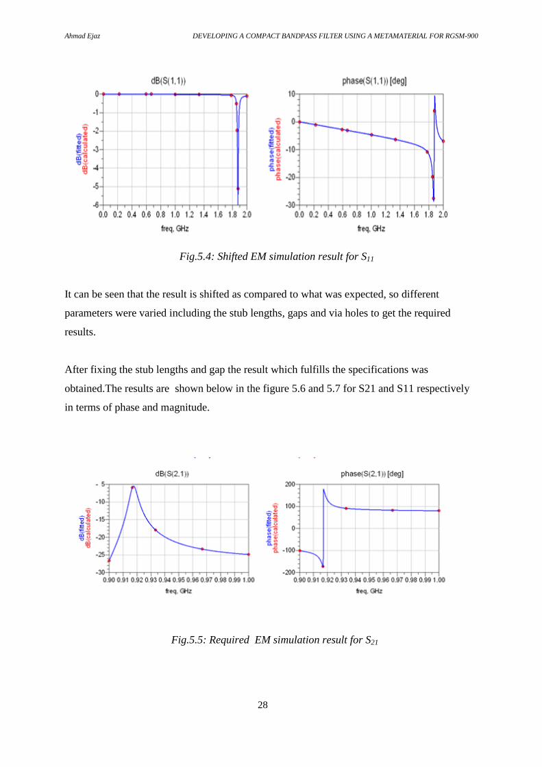
5.4.Simulation results:
After completing the simulation, the results obtained are shown below in the figure 5.4 and
5.5 for S21 and S11 respectively in terms of phase and magnitude.
Fig.5.3: Shifted EM simulation result for S21
Ahmad Ejaz DEVELOPING A COMPACT BANDPASS FILTER USING A METAMATERIAL FOR RGSM-900
28
Fig.5.4: Shifted EM simulation result for S11
It can be seen that the result is shifted as compared to what was expected, so different
parameters were varied including the stub lengths, gaps and via holes to get the required
results.
After fixing the stub lengths and gap the result which fulfills the specifications was
obtained.The results are shown below in the figure 5.6 and 5.7 for S21 and S11 respectively
in terms of phase and magnitude.
Fig.5.5: Required EM simulation result for S21

Ahmad Ejaz DEVELOPING A COMPACT BANDPASS FILTER USING A METAMATERIAL FOR RGSM-900
29
Fig.5.6: Required EM simulation result for S11
As can be seen from the above figure good performance is obtained at the required GSM-900
frequency for return loss and insertion loss.
In Figure 5.8 software generated 3-D views of the layout is shown.
Fig.5.7 : ADS 3-D Preview
Furthermore we can compute the far field from the simulation results of the current EM setup
as shown in the Fig. 5.9 below.

Ahmad Ejaz DEVELOPING A COMPACT BANDPASS FILTER USING A METAMATERIAL FOR RGSM-900
30
Fig5.8: Far field visualization
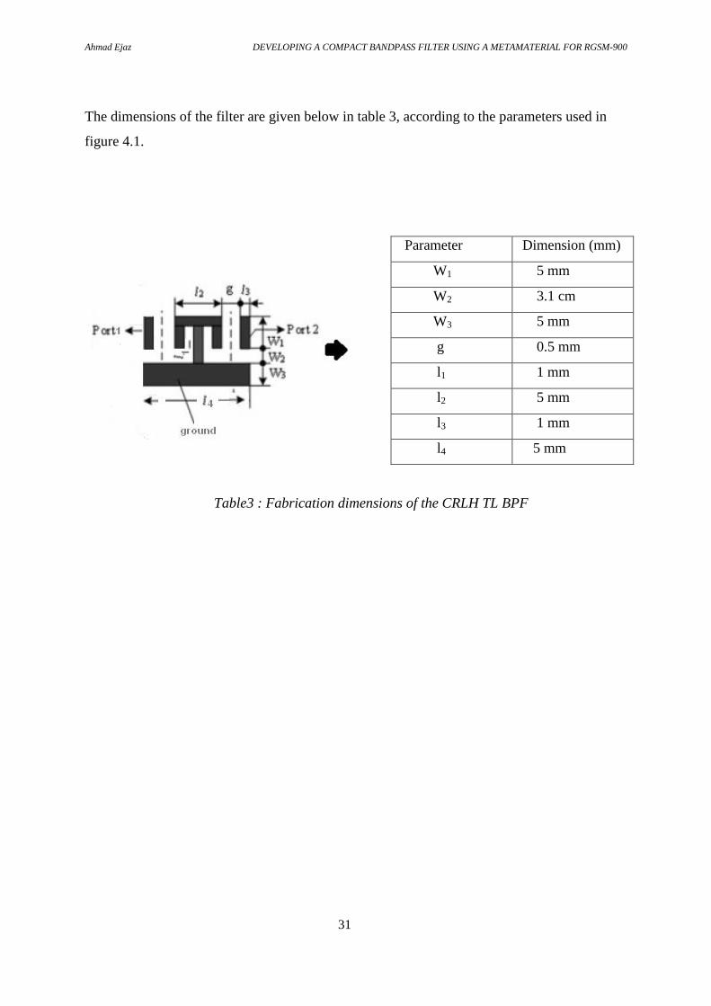
The final filter layout for the manufacturing is shown below in the figure5.10.
Fig5.9: Filter Layout for fabrication
Ahmad Ejaz DEVELOPING A COMPACT BANDPASS FILTER USING A METAMATERIAL FOR RGSM-900
31
The dimensions of the filter are given below in table 3, according to the parameters used in
figure 4.1.
Table3 : Fabrication dimensions of the CRLH TL BPF
Parameter Dimension (mm)
W1 5 mm
W2 3.1 cm
W3 5 mm
g 0.5 mm
l1 1 mm
l2 5 mm
l3 1 mm
l4 5 mm

Ahmad Ejaz DEVELOPING A COMPACT BANDPASS FILTER USING A METAMATERIAL FOR RGSM-900
32
Discussion and Conclusions:
The aim of the project “Developing a compact bandpass filter using metamaterial structure
for RGSM-900” was achieved.The required filter specifications are obtained at centre
frequency 918.2 MHz by using the substrate Rogers 5880.The simulation results also show
that the substrate material with higher thickness gives a more compact structure with low
insertion loss and high return loss.
In comparison with the conventional filters, designing filter using CRLH metamaterials is
simple due to easy structures. In addition metamaterial structures enhance the performance
along with a remarkable size reduction as compared to conventional filters, varies from filter
to filter and ranges from 30 % to 80 % [8].
In this CRLH design 1-cell type by using Rogers 5880 as the substrate material , minimum
insertion loss along with return loss of -18 dB at centre specified frequency 918.2 MHz using
EM simulation is obtained which is the expected result of a manufactured filter.
This proposed bandpass filter has a total dimension of 4.2 cm × 2 cm , which is considerable
compact size as compared to conventional filters, cavity filter operating at 900 MHz
frequency range has size upto 11 inches, which makes it very useful in different applications.
Ahmad Ejaz DEVELOPING A COMPACT BANDPASS FILTER USING A METAMATERIAL FOR RGSM-900
33
References:
[1] D. M. Pozar. Microwave Engineering, John Wiley & Sons, New Jersey 2005.
[2] G, M.; Bonache, J.; Selga, J.; Garcia-Garcia, J.; Martin, F., "Broadband Resonant-Type
Metamaterial Transmission Lines,"IEEE Microwave and Wireless Components Letters ,
vol.17, no.2, pp.97-99, Feb. 2007
[3] L, Liu K. Y., Li F., “A microstrip highpass filter with complementary split ring
resonators” PIERS Online, Vol. 3, pp 583-586, 2007, November 2007
[4] J. S. Hong and Lancaster, M. J. Microstrip Filters for RF/Microwave Applications,
John Wiley & Sons, New York 2001.
[5] K. Esfeh. B. , Ismail. A., Abdullah. R. S. A. R., Alhawari. A. R. H. and Adam. H.
(2009). Compact Narrowband Bandpass Filter Using Dual –Mode Octagonal Meandered
Loop Resonator. Progress In Electromagnetics Research B, vol. 16, 277-290, 2009.
[6] M.Ricardo, Martin, F., and Sorolla, Mario, “Metamaterials with Negative
Parameters: Theory, Design, and Microwave Applications” John Wiley and Sons Inc , 2007
[7] M.Gil; Bonache, J.; Gil, I.; Garcia-Garcia, J.; Martin, F, “On the transmission properties
of left-handed microstrip lines implemented by complementary split ring resonators”,
International J of Numerical Modelling, Vol. 19, Issue 2, pp. 87-103, April 2006
[8] H.Tao, N. I. Landy, Kebin Fan, A. C. Strikwerda, W. J. Padilla, R. D. Averitt, and Xin
Zhang, “Flexible Terahertz Metamaterials: Towards a Terahertz Metamaterial Invisible
Cloak” IEDM 2008 IEEE International, Vol. 41,pp. 13- 24, Dec 2008.
[9] Q. Zhang, S. Naeem Khan, and S. He, “Realization of left handness through CSRRs and
SRRs in microstrip line, Microwave and Optical Technology Letters, vol. 51, No. 3, March
2009.
[10] V.M. Shalaev, Wenshan Cai, Uday K. Chettiar, Hsiao-Kuan Yuan, Andrey K.
Sarychev, Vladimir P. Drachev, and Alexander V. Kildishev, “Negative index of
refraction in optical metamaterials”, Optics Letters, Vol. 30, Issue 24, pp. 3356-3358
2005
[11] J.Valentine1,3, Shuang Zhang1,3, Thomas Zentgraf1,3, Erick Ulin-Avila1, Dentcho A.
Genov1, Guy Bartal1 & Xiang Zhang, “Three-dimensional optical metamaterial with a
negative refractive index”, Nature vol. 455, pp. 376-379, September 2008
[12] D. Schurig1, J. J. Mock, B. J. Justice, S. A. Cummer, J. B. Pendry, A. F. Starr and D. R.
Smith, “Metamaterial Electromagnetic Cloak at Microwave Frquencies”, Science
Vol. 314 no. 5801 pp. 977-980 November 2006.
[13] R.Marqués, Francisco Mesa, Jesús Martel, and Francisco Medina, “Comparative

Ahmad Ejaz DEVELOPING A COMPACT BANDPASS FILTER USING A METAMATERIAL FOR RGSM-900
34
Analysis of Edge- and Broadside-Coupled Split Ring Resonators for Metamaterial Design
– Theory and Experiments”, IEEE Transactions on Antennas and Propagation, Vol. 51, No.
10, pp. 441- 443 October 2003.
[14] J.Richard Metamaterial Filters on LCP substrate using MEMS Technology: Graduate
faculty of Auburn University, Alabama ,pp.6-9, December 12, 2011
[15] P.Kapitanova; K. D. Humbla, S. Perrone, R . Mueller, J. Hein, M.A.Vendik,
"IEEE Multi-band and tunable multi-band microwave resonators and filters based on
cascaded left/right-handed transmission line sections ", EUROCON 2009,
vol. 7, pp.18-23, 39-45 ,May 2009
[16] L. Jiusheng, and Y. Zhuang, “Compact microstrip bandpass filter using composite
right/left-handed transmission lines,” Microwave and Optical Technology Letters, vol. 49,
pp. 1929-1931, 2007.
[17] C.K. Wu, K.L. Wong, Microwave and Optical Technology Letters, vol. 22, no. 5, pp.
348-349, 1999.
[18] X.Wang, Jonathan Engel and Chang Liu, “Liquid crystal polymer (LCP) for
MEMS: processes and applications,” Journal of Micromechanics and
Microengineering, Vol. 13, No. 5, 2003
[19] http://www.rogerscorp.com/acm/index.aspx
[20] H.Tao, A.C. Strikwerda, K. Fan, C.M. Bingham, W. J. Padilla, Xin Zhang, and R.
D. Averitt, “Terahertz metamaterials on free-standing highly-flexible polyimide
substrates,” Journal of Physics D: Applied physics, Vol. 41, No. 23, Dec. 13, 2008
[21] M.K.Haldar, Hieng Tiong Su and Kian Kiong Fong. Dual Mode Microstrip Ring
Resonator with Composite-Right/Left-handed Line: Swinburne University of
Technology (Sarawak Campus) Sarawak, Malaysia.
[22] R. A. Shelby, D. R. Smith, and S. Schultz, “Experimental verification of a negative
index of refraction,” Science, vol 292, no. 5514, pp.77-79, 2001.
[23] A.R. Mishra “ Fundamentals of Cellular Network Planning and Optimisation ” John
Wiley & Sons, England 2007.