
Developer XD 2.0 · iv Developer XD 2.0.4 1.3.1 Supported Domains. . . . . . . . . . . . . . . . ....
436
Definiens Developer XD 2.0.4 Reference Book
Transcript of Developer XD 2.0 · iv Developer XD 2.0.4 1.3.1 Supported Domains. . . . . . . . . . . . . . . . ....

Definiens
Developer XD 2.0.4
Reference Book

Definiens Documentation:
Developer XD 2.0.4
Reference BookImprint
© 2012 Definiens AG. All rights reserved. This document may be copied andprinted only in accordance with the terms of the Frame License Agreement forEnd Users of the related Definiens software.
Published by:
Definiens AG, Bernhard-Wicki-Straße 5, 80636 München, GermanyPhone: +49 89 2311 800 • Fax: +49 89 2311 8090Web: www.definiens.com
Dear User,
Thank you for using Definiens software. We appreciate being of service toyou with image intelligence solutions. At Definiens we constantly strive toimprove our products. We therefore appreciate all comments and suggestionsfor improvements concerning our software, training, and documentation. Feelfree to contact us via web form on the Definiens support website www.definiens.com/support
Thank you.
Legal Notes
Definiens®, Definiens Cellenger®, Definiens Cognition Network Technology®,DEFINIENS ENTERPRISE IMAGE INTELLIGENCE®, Tissue Studio® andUnderstanding Images® are registered trademarks of Definiens AG in Germanyand other countries. Cognition Network Technology™, Enterprise Image Intel-ligence™ and Definiens Composer Technology™ are trademarks of DefiniensAG in Germany and other countries.
All other product names, company names, and brand names mentioned in thisdocument may be trademark properties of their respective holders.
Protected by patents EP0858051; WO0145033; WO2004036337; US6,832,002; US 7,437,004; US 7,574,053 B2; US 7,146,380; US 7,467,159 B;US 7,873,223; US 7,801,361 B2.
Regulatory affairs
Under certain circumstances the solutions and applications developed usingDefiniens Developer XD may fall under specific regulations (e.g. medical de-vice or IVD regulations) in your country. Please ensure that you check andfollow local regulations before using or taking your solution or application intocommerce. If you require specific data about Definiens Developer XD, pleasecontact your dealer or our sales staff.
* * *
Typeset by Wikipublisher
All rights reserved.© 2012 Definiens Documentation, München, Germany
Day of print: 05 September 2012

Contents
Introduction 1Symbols and Expressions . . . . . . . . . . . . . . . . . . . . . . . . . . . . . 1
Basic Mathematical Notations . . . . . . . . . . . . . . . . . . . . . . . 1Image Layer and Scene . . . . . . . . . . . . . . . . . . . . . . . . . . . 1Region . . . . . . . . . . . . . . . . . . . . . . . . . . . . . . . . . . . . 2Pixel Set . . . . . . . . . . . . . . . . . . . . . . . . . . . . . . . . . . . 2Image Object . . . . . . . . . . . . . . . . . . . . . . . . . . . . . . . . 3Image Objects Hierarchy . . . . . . . . . . . . . . . . . . . . . . . . . . 3Class-Related Set . . . . . . . . . . . . . . . . . . . . . . . . . . . . . . 3
Co-ordinate Systems Used in Definiens Software . . . . . . . . . . . . . . . . 4Pixel Co-ordinate System . . . . . . . . . . . . . . . . . . . . . . . . . . 4User Co-ordinate System . . . . . . . . . . . . . . . . . . . . . . . . . . 5
Image Layer Related Features . . . . . . . . . . . . . . . . . . . . . . . . . . 6Scene . . . . . . . . . . . . . . . . . . . . . . . . . . . . . . . . . . . . 6Maps . . . . . . . . . . . . . . . . . . . . . . . . . . . . . . . . . . . . 7Region . . . . . . . . . . . . . . . . . . . . . . . . . . . . . . . . . . . . 8Image Layer . . . . . . . . . . . . . . . . . . . . . . . . . . . . . . . . . 8Image Layer Intensity on Pixel Sets . . . . . . . . . . . . . . . . . . . . 9
Image Object Related Features . . . . . . . . . . . . . . . . . . . . . . . . . . 10Image Object . . . . . . . . . . . . . . . . . . . . . . . . . . . . . . . . 10Image Object Hierarchy . . . . . . . . . . . . . . . . . . . . . . . . . . . 14
Class-Related Features . . . . . . . . . . . . . . . . . . . . . . . . . . . . . . 16Class-Related Sets . . . . . . . . . . . . . . . . . . . . . . . . . . . . . 16
Shape-Related Features . . . . . . . . . . . . . . . . . . . . . . . . . . . . . . 17Parameters . . . . . . . . . . . . . . . . . . . . . . . . . . . . . . . . . . 17Expression . . . . . . . . . . . . . . . . . . . . . . . . . . . . . . . . . . 17Shape Approximations Based on Eigenvalues . . . . . . . . . . . . . . . 17Elliptic Approximation . . . . . . . . . . . . . . . . . . . . . . . . . . . 18
About Algorithms . . . . . . . . . . . . . . . . . . . . . . . . . . . . . . . . . 19Creating a Process . . . . . . . . . . . . . . . . . . . . . . . . . . . . . . 19Specifying Algorithm Parameters . . . . . . . . . . . . . . . . . . . . . . 19
1 Process-Related Operation Algorithms 211.1 Execute Child Processes . . . . . . . . . . . . . . . . . . . . . . . . . . 21
1.1.1 Supported Domains . . . . . . . . . . . . . . . . . . . . . . . . . 211.2 Execute Child As Series . . . . . . . . . . . . . . . . . . . . . . . . . . 23
1.2.1 Supported Domains . . . . . . . . . . . . . . . . . . . . . . . . . 231.2.2 Algorithm Parameters . . . . . . . . . . . . . . . . . . . . . . . 23
1.3 If, Then and Else . . . . . . . . . . . . . . . . . . . . . . . . . . . . . . 23
iii
iv Developer XD 2.0.4
1.3.1 Supported Domains . . . . . . . . . . . . . . . . . . . . . . . . . 231.4 Throw . . . . . . . . . . . . . . . . . . . . . . . . . . . . . . . . . . . . 23
1.4.1 Supported Domains . . . . . . . . . . . . . . . . . . . . . . . . . 231.5 Catch . . . . . . . . . . . . . . . . . . . . . . . . . . . . . . . . . . . . 24
1.5.1 Supported Domains . . . . . . . . . . . . . . . . . . . . . . . . . 241.6 Set Rule Set Options . . . . . . . . . . . . . . . . . . . . . . . . . . . . 24
1.6.1 Supported Domains . . . . . . . . . . . . . . . . . . . . . . . . . 241.6.2 Algorithm Parameters . . . . . . . . . . . . . . . . . . . . . . . 24
2 Segmentation Algorithms 272.1 Chessboard Segmentation . . . . . . . . . . . . . . . . . . . . . . . . . . 27
2.1.1 Supported Domains . . . . . . . . . . . . . . . . . . . . . . . . . 282.1.2 Algorithm Parameters . . . . . . . . . . . . . . . . . . . . . . . 28
2.2 Quadtree-Based Segmentation . . . . . . . . . . . . . . . . . . . . . . . 282.2.1 Supported Domains . . . . . . . . . . . . . . . . . . . . . . . . . 292.2.2 Algorithm Parameters . . . . . . . . . . . . . . . . . . . . . . . 292.2.3 Thematic Layer Weights . . . . . . . . . . . . . . . . . . . . . . 31
2.3 Contrast Split Segmentation . . . . . . . . . . . . . . . . . . . . . . . . 312.3.1 Supported Domains . . . . . . . . . . . . . . . . . . . . . . . . . 312.3.2 Settings . . . . . . . . . . . . . . . . . . . . . . . . . . . . . . . 312.3.3 Advanced Settings . . . . . . . . . . . . . . . . . . . . . . . . . 33
2.4 Multiresolution Segmentation . . . . . . . . . . . . . . . . . . . . . . . 342.4.1 Supported Domains . . . . . . . . . . . . . . . . . . . . . . . . . 362.4.2 Level Settings . . . . . . . . . . . . . . . . . . . . . . . . . . . . 362.4.3 Segmentation Settings . . . . . . . . . . . . . . . . . . . . . . . 372.4.4 Composition of Homogeneity Criterion . . . . . . . . . . . . . . 37
2.5 Spectral Difference Segmentation . . . . . . . . . . . . . . . . . . . . . 392.5.1 Supported Domains . . . . . . . . . . . . . . . . . . . . . . . . . 392.5.2 Level Settings . . . . . . . . . . . . . . . . . . . . . . . . . . . . 392.5.3 Segmentation Settings . . . . . . . . . . . . . . . . . . . . . . . 39
2.6 Multi-Threshold Segmentation . . . . . . . . . . . . . . . . . . . . . . . 402.6.1 Supported Domains . . . . . . . . . . . . . . . . . . . . . . . . . 402.6.2 Level Settings . . . . . . . . . . . . . . . . . . . . . . . . . . . . 40
2.7 Contrast Filter Segmentation . . . . . . . . . . . . . . . . . . . . . . . . 422.7.1 Supported Domains . . . . . . . . . . . . . . . . . . . . . . . . . 422.7.2 Chessboard Settings . . . . . . . . . . . . . . . . . . . . . . . . 422.7.3 Input Parameters . . . . . . . . . . . . . . . . . . . . . . . . . . 422.7.4 ShapeCriteria Settings . . . . . . . . . . . . . . . . . . . . . . . 442.7.5 Classification Parameters . . . . . . . . . . . . . . . . . . . . . . 44
2.8 Watershed Segmentation . . . . . . . . . . . . . . . . . . . . . . . . . . 452.8.1 Examples . . . . . . . . . . . . . . . . . . . . . . . . . . . . . . 452.8.2 Supported Domains . . . . . . . . . . . . . . . . . . . . . . . . . 462.8.3 Algorithm Parameters . . . . . . . . . . . . . . . . . . . . . . . 46
3 Basic Classification Algorithms 473.1 Assign Class . . . . . . . . . . . . . . . . . . . . . . . . . . . . . . . . . 47
3.1.1 Use Class . . . . . . . . . . . . . . . . . . . . . . . . . . . . . . 473.2 Classification . . . . . . . . . . . . . . . . . . . . . . . . . . . . . . . . 47
3.2.1 Active Classes . . . . . . . . . . . . . . . . . . . . . . . . . . . 473.3 Hierarchical Classification . . . . . . . . . . . . . . . . . . . . . . . . . 48
3.3.1 Active Classes . . . . . . . . . . . . . . . . . . . . . . . . . . . 48
05 September 2012 Reference Book
CONTENTS v
3.3.2 Use Class-Related Features . . . . . . . . . . . . . . . . . . . . . 483.4 Remove Classification . . . . . . . . . . . . . . . . . . . . . . . . . . . 48
3.4.1 Classes . . . . . . . . . . . . . . . . . . . . . . . . . . . . . . . 483.4.2 Process . . . . . . . . . . . . . . . . . . . . . . . . . . . . . . . 483.4.3 Manual . . . . . . . . . . . . . . . . . . . . . . . . . . . . . . . 49
4 Advanced Classification Algorithms 514.1 Find Domain Extrema . . . . . . . . . . . . . . . . . . . . . . . . . . . . 51
4.1.1 Supported Domains . . . . . . . . . . . . . . . . . . . . . . . . . 514.1.2 Extrema Settings . . . . . . . . . . . . . . . . . . . . . . . . . . 524.1.3 Classification Settings . . . . . . . . . . . . . . . . . . . . . . . 52
4.2 Find Local Extrema . . . . . . . . . . . . . . . . . . . . . . . . . . . . . 534.2.1 Supported Domains . . . . . . . . . . . . . . . . . . . . . . . . . 534.2.2 Search Settings . . . . . . . . . . . . . . . . . . . . . . . . . . . 534.2.3 Conditions . . . . . . . . . . . . . . . . . . . . . . . . . . . . . 544.2.4 Classification Settings . . . . . . . . . . . . . . . . . . . . . . . 54
4.3 Find Enclosed by Class . . . . . . . . . . . . . . . . . . . . . . . . . . . 554.3.1 Supported Domains . . . . . . . . . . . . . . . . . . . . . . . . . 554.3.2 Search Settings . . . . . . . . . . . . . . . . . . . . . . . . . . . 554.3.3 Classification Settings . . . . . . . . . . . . . . . . . . . . . . . 56
4.4 Find Enclosed by Image Object . . . . . . . . . . . . . . . . . . . . . . . 564.4.1 Classification Settings . . . . . . . . . . . . . . . . . . . . . . . 56
4.5 Connector . . . . . . . . . . . . . . . . . . . . . . . . . . . . . . . . . . 574.5.1 Connector Settings . . . . . . . . . . . . . . . . . . . . . . . . . 584.5.2 Classification Settings . . . . . . . . . . . . . . . . . . . . . . . 59
4.6 Assign Class By Slice Overlap (Prototype) . . . . . . . . . . . . . . . . . 594.6.1 Supported Domains . . . . . . . . . . . . . . . . . . . . . . . . . 594.6.2 Algorithm Parameters . . . . . . . . . . . . . . . . . . . . . . . 59
4.7 Optimal Box (Prototype) . . . . . . . . . . . . . . . . . . . . . . . . . . 604.7.1 Supported Domains . . . . . . . . . . . . . . . . . . . . . . . . . 604.7.2 Sample Class Parameters . . . . . . . . . . . . . . . . . . . . . . 604.7.3 Insert Membership Function Parameters . . . . . . . . . . . . . . 604.7.4 Feature Optimization Parameters . . . . . . . . . . . . . . . . . . 614.7.5 Optimization Settings Parameters . . . . . . . . . . . . . . . . . 614.7.6 Optimization Output Parameters . . . . . . . . . . . . . . . . . . 62
4.8 Classifier . . . . . . . . . . . . . . . . . . . . . . . . . . . . . . . . . . 634.8.1 Supported Domains . . . . . . . . . . . . . . . . . . . . . . . . . 634.8.2 General Parameters . . . . . . . . . . . . . . . . . . . . . . . . . 634.8.3 Train: General Parameters . . . . . . . . . . . . . . . . . . . . . 644.8.4 Train: Feature Parameters . . . . . . . . . . . . . . . . . . . . . 644.8.5 Train: Classifier Parameters . . . . . . . . . . . . . . . . . . . . 644.8.6 Apply: General Parameters . . . . . . . . . . . . . . . . . . . . 644.8.7 Apply: Feature Parameters . . . . . . . . . . . . . . . . . . . . . 654.8.8 Query: General Parameters . . . . . . . . . . . . . . . . . . . . 654.8.9 Query: Query Information about a trained classifier . . . . . . . 65
5 Variables Operation Algorithms 675.1 Timer . . . . . . . . . . . . . . . . . . . . . . . . . . . . . . . . . . . . 67
5.1.1 Supported Domains . . . . . . . . . . . . . . . . . . . . . . . . . 675.1.2 Algorithm Parameters . . . . . . . . . . . . . . . . . . . . . . . 67
5.2 Update Variable . . . . . . . . . . . . . . . . . . . . . . . . . . . . . . . 67
Reference Book 05 September 2012
vi Developer XD 2.0.4
5.2.1 Supported Domains . . . . . . . . . . . . . . . . . . . . . . . . . 675.2.2 Algorithm Parameters . . . . . . . . . . . . . . . . . . . . . . . 68
5.3 Compute Statistical Value . . . . . . . . . . . . . . . . . . . . . . . . . . 695.3.1 Supported Domains . . . . . . . . . . . . . . . . . . . . . . . . . 695.3.2 Active Classes . . . . . . . . . . . . . . . . . . . . . . . . . . . 705.3.3 Algorithm Parameters . . . . . . . . . . . . . . . . . . . . . . . 70
5.4 Compose Text . . . . . . . . . . . . . . . . . . . . . . . . . . . . . . . . 715.4.1 Supported Domains . . . . . . . . . . . . . . . . . . . . . . . . . 715.4.2 Algorithm Parameters . . . . . . . . . . . . . . . . . . . . . . . 71
5.5 Update Region . . . . . . . . . . . . . . . . . . . . . . . . . . . . . . . 725.5.1 Supported Domains . . . . . . . . . . . . . . . . . . . . . . . . . 725.5.2 Algorithm Parameters . . . . . . . . . . . . . . . . . . . . . . . 72
5.6 Update Image Object List . . . . . . . . . . . . . . . . . . . . . . . . . . 725.6.1 Supported Domains . . . . . . . . . . . . . . . . . . . . . . . . . 725.6.2 Algorithm Parameters . . . . . . . . . . . . . . . . . . . . . . . 74
5.7 Update Feature List . . . . . . . . . . . . . . . . . . . . . . . . . . . . . 745.7.1 Supported Domains . . . . . . . . . . . . . . . . . . . . . . . . . 74
5.8 Automatic Threshold . . . . . . . . . . . . . . . . . . . . . . . . . . . . 745.8.1 Supported Domains . . . . . . . . . . . . . . . . . . . . . . . . . 765.8.2 Algorithm Parameters . . . . . . . . . . . . . . . . . . . . . . . 76
5.9 Update Array . . . . . . . . . . . . . . . . . . . . . . . . . . . . . . . . 775.9.1 Supported Domains . . . . . . . . . . . . . . . . . . . . . . . . . 775.9.2 Algorithm Parameters . . . . . . . . . . . . . . . . . . . . . . . 77
6 Basic Object Reshaping Algorithms 796.1 Remove Objects . . . . . . . . . . . . . . . . . . . . . . . . . . . . . . . 79
6.1.1 Supported Domains . . . . . . . . . . . . . . . . . . . . . . . . . 796.1.2 Algorithm Parameters . . . . . . . . . . . . . . . . . . . . . . . 79
6.2 Merge Region . . . . . . . . . . . . . . . . . . . . . . . . . . . . . . . . 806.2.1 Supported Domains . . . . . . . . . . . . . . . . . . . . . . . . . 806.2.2 Algorithm Parameters . . . . . . . . . . . . . . . . . . . . . . . 80
6.3 Grow Region . . . . . . . . . . . . . . . . . . . . . . . . . . . . . . . . 816.3.1 Supported Domains . . . . . . . . . . . . . . . . . . . . . . . . . 816.3.2 Algorithm Parameters . . . . . . . . . . . . . . . . . . . . . . . 81
6.4 Convert to Sub-objects . . . . . . . . . . . . . . . . . . . . . . . . . . . 826.4.1 Supported Domains . . . . . . . . . . . . . . . . . . . . . . . . . 826.4.2 Algorithm Parameters . . . . . . . . . . . . . . . . . . . . . . . 82
6.5 Convert Image Objects . . . . . . . . . . . . . . . . . . . . . . . . . . . 826.5.1 Supported Domains . . . . . . . . . . . . . . . . . . . . . . . . . 826.5.2 Algorithm Parameters . . . . . . . . . . . . . . . . . . . . . . . 83
6.6 Cut Objects at Region . . . . . . . . . . . . . . . . . . . . . . . . . . . . 846.6.1 Supported Domains . . . . . . . . . . . . . . . . . . . . . . . . . 846.6.2 Algorithm Parameters . . . . . . . . . . . . . . . . . . . . . . . 84
7 Advanced Object Reshaping Algorithms 877.1 Shape Split (Prototype) . . . . . . . . . . . . . . . . . . . . . . . . . . . 87
7.1.1 Supported Domains . . . . . . . . . . . . . . . . . . . . . . . . . 877.1.2 Algorithm Parameters . . . . . . . . . . . . . . . . . . . . . . . 87
7.2 Multiresolution Segmentation Region Grow . . . . . . . . . . . . . . . . 887.2.1 Supported Domains . . . . . . . . . . . . . . . . . . . . . . . . . 887.2.2 Image Layer Weights . . . . . . . . . . . . . . . . . . . . . . . . 88
05 September 2012 Reference Book
CONTENTS vii
7.2.3 Thematic Layer Usage . . . . . . . . . . . . . . . . . . . . . . . 887.2.4 Composition of Homogeneity Criteria . . . . . . . . . . . . . . . 88
7.3 Image Object Fusion . . . . . . . . . . . . . . . . . . . . . . . . . . . . 897.3.1 Supported Domains . . . . . . . . . . . . . . . . . . . . . . . . . 897.3.2 Candidate Settings . . . . . . . . . . . . . . . . . . . . . . . . . 897.3.3 Fitting Function . . . . . . . . . . . . . . . . . . . . . . . . . . . 907.3.4 Weighted Sum . . . . . . . . . . . . . . . . . . . . . . . . . . . 917.3.5 Merge Settings . . . . . . . . . . . . . . . . . . . . . . . . . . . 917.3.6 Classification Settings . . . . . . . . . . . . . . . . . . . . . . . 92
7.4 Border Optimization . . . . . . . . . . . . . . . . . . . . . . . . . . . . 927.4.1 Supported Domains . . . . . . . . . . . . . . . . . . . . . . . . . 927.4.2 Border Optimization Settings . . . . . . . . . . . . . . . . . . . 937.4.3 Classification Settings . . . . . . . . . . . . . . . . . . . . . . . 93
7.5 Morphology . . . . . . . . . . . . . . . . . . . . . . . . . . . . . . . . . 947.5.1 Supported Domains . . . . . . . . . . . . . . . . . . . . . . . . . 947.5.2 Morphology Settings . . . . . . . . . . . . . . . . . . . . . . . . 947.5.3 Classification Settings . . . . . . . . . . . . . . . . . . . . . . . 95
7.6 Watershed Transformation . . . . . . . . . . . . . . . . . . . . . . . . . 967.6.1 Supported Domains . . . . . . . . . . . . . . . . . . . . . . . . . 967.6.2 Watershed Settings . . . . . . . . . . . . . . . . . . . . . . . . . 967.6.3 Classification Settings . . . . . . . . . . . . . . . . . . . . . . . 96
8 Pixel-Based Object Reshaping Algorithms 998.1 Pixel-Based Object Resizing . . . . . . . . . . . . . . . . . . . . . . . . 99
8.1.1 Supported Domains . . . . . . . . . . . . . . . . . . . . . . . . . 998.1.2 Algorithm Parameters . . . . . . . . . . . . . . . . . . . . . . . 998.1.3 Candidate Object Domain Parameters . . . . . . . . . . . . . . . 1018.1.4 Pixel Level Constraint Parameters . . . . . . . . . . . . . . . . . 1018.1.5 Candidate Surface Tension Parameters . . . . . . . . . . . . . . . 1028.1.6 Size Limits Parameters . . . . . . . . . . . . . . . . . . . . . . . 105
8.2 Pixel-Based Density Filter . . . . . . . . . . . . . . . . . . . . . . . . . 1068.2.1 Supported Domains . . . . . . . . . . . . . . . . . . . . . . . . . 1068.2.2 Algorithm Parameters . . . . . . . . . . . . . . . . . . . . . . . 1068.2.3 Growing and Shrinking Directions Parameters . . . . . . . . . . 1078.2.4 Density Criteria Parameters . . . . . . . . . . . . . . . . . . . . 108
8.3 Pixel-Based Shape Processing Filters . . . . . . . . . . . . . . . . . . . . 1098.3.1 Supported Domains . . . . . . . . . . . . . . . . . . . . . . . . . 1108.3.2 Algorithm Parameters . . . . . . . . . . . . . . . . . . . . . . . 110
9 Linking Operation Algorithms 1179.1 Create Links . . . . . . . . . . . . . . . . . . . . . . . . . . . . . . . . . 117
9.1.1 Supported Domains . . . . . . . . . . . . . . . . . . . . . . . . . 1179.1.2 Algorithm Parameters . . . . . . . . . . . . . . . . . . . . . . . 1189.1.3 Candidate Object Domain Parameters . . . . . . . . . . . . . . . 1189.1.4 Overlap Settings Parameters . . . . . . . . . . . . . . . . . . . . 118
9.2 Delete Links . . . . . . . . . . . . . . . . . . . . . . . . . . . . . . . . . 1209.2.1 Supported Domains . . . . . . . . . . . . . . . . . . . . . . . . . 1209.2.2 Algorithm Parameters . . . . . . . . . . . . . . . . . . . . . . . 120
10 Level Operation Algorithms 12110.1 Copy Image Object Level . . . . . . . . . . . . . . . . . . . . . . . . . . 121
Reference Book 05 September 2012

viii Developer XD 2.0.4
10.1.1 Supported Domains . . . . . . . . . . . . . . . . . . . . . . . . . 12110.1.2 Algorithm Parameters . . . . . . . . . . . . . . . . . . . . . . . 121
10.2 Delete Image Object Level . . . . . . . . . . . . . . . . . . . . . . . . . 12110.2.1 Supported Domains . . . . . . . . . . . . . . . . . . . . . . . . . 121
10.3 Rename Image Object Level . . . . . . . . . . . . . . . . . . . . . . . . 12210.3.1 Supported Domains . . . . . . . . . . . . . . . . . . . . . . . . . 12210.3.2 Algorithm Parameters . . . . . . . . . . . . . . . . . . . . . . . 122
11 Map Operations Algorithms 12311.1 Copy Map . . . . . . . . . . . . . . . . . . . . . . . . . . . . . . . . . . 123
11.1.1 Supported Domains . . . . . . . . . . . . . . . . . . . . . . . . . 12311.1.2 Algorithm Parameters . . . . . . . . . . . . . . . . . . . . . . . 123
11.2 Delete Map . . . . . . . . . . . . . . . . . . . . . . . . . . . . . . . . . 12611.2.1 Supported Domains . . . . . . . . . . . . . . . . . . . . . . . . . 126
11.3 Synchronize Map . . . . . . . . . . . . . . . . . . . . . . . . . . . . . . 12611.3.1 Supported Domains . . . . . . . . . . . . . . . . . . . . . . . . . 12711.3.2 Algorithm Parameters . . . . . . . . . . . . . . . . . . . . . . . 127
11.4 3D/4D Settings . . . . . . . . . . . . . . . . . . . . . . . . . . . . . . . 12811.4.1 Supported Domains . . . . . . . . . . . . . . . . . . . . . . . . . 12811.4.2 Algorithm Parameters . . . . . . . . . . . . . . . . . . . . . . . 128
11.5 Scene Properties . . . . . . . . . . . . . . . . . . . . . . . . . . . . . . . 12911.5.1 Supported Domains . . . . . . . . . . . . . . . . . . . . . . . . . 12911.5.2 Algorithm Parameters . . . . . . . . . . . . . . . . . . . . . . . 130
12 Image Layer Operation Algorithms 13112.1 Distance Map . . . . . . . . . . . . . . . . . . . . . . . . . . . . . . . . 131
12.1.1 Supported Domains . . . . . . . . . . . . . . . . . . . . . . . . . 13112.1.2 Algorithm Parameters . . . . . . . . . . . . . . . . . . . . . . . 131
12.2 Create Temporary Image Layer . . . . . . . . . . . . . . . . . . . . . . . 13212.2.1 Supported Domains . . . . . . . . . . . . . . . . . . . . . . . . . 13212.2.2 Algorithm Parameters . . . . . . . . . . . . . . . . . . . . . . . 132
12.3 Delete Layer . . . . . . . . . . . . . . . . . . . . . . . . . . . . . . . . . 13212.3.1 Supported Domains . . . . . . . . . . . . . . . . . . . . . . . . . 13312.3.2 Algorithm Parameters . . . . . . . . . . . . . . . . . . . . . . . 133
12.4 Convolution Filter . . . . . . . . . . . . . . . . . . . . . . . . . . . . . . 13312.4.1 Supported Domains . . . . . . . . . . . . . . . . . . . . . . . . . 13312.4.2 Algorithm Parameters . . . . . . . . . . . . . . . . . . . . . . . 13312.4.3 Kernel Parameters . . . . . . . . . . . . . . . . . . . . . . . . . 13412.4.4 Layers Parameters . . . . . . . . . . . . . . . . . . . . . . . . . 134
12.5 Layer Normalization . . . . . . . . . . . . . . . . . . . . . . . . . . . . 13512.5.1 Supported Domains . . . . . . . . . . . . . . . . . . . . . . . . . 13612.5.2 Algorithm Parameters . . . . . . . . . . . . . . . . . . . . . . . 13612.5.3 Layers Parameters . . . . . . . . . . . . . . . . . . . . . . . . . 136
12.6 Median Filter . . . . . . . . . . . . . . . . . . . . . . . . . . . . . . . . 13712.6.1 Supported Domains . . . . . . . . . . . . . . . . . . . . . . . . . 13712.6.2 Kernel Parameters . . . . . . . . . . . . . . . . . . . . . . . . . 13712.6.3 Layers Parameters . . . . . . . . . . . . . . . . . . . . . . . . . 137
12.7 Sobel Operation Filter . . . . . . . . . . . . . . . . . . . . . . . . . . . . 13812.7.1 Supported Domains . . . . . . . . . . . . . . . . . . . . . . . . . 13812.7.2 Kernel Parameters . . . . . . . . . . . . . . . . . . . . . . . . . 13812.7.3 Layers Parameters . . . . . . . . . . . . . . . . . . . . . . . . . 139
05 September 2012 Reference Book

CONTENTS ix
12.8 Pixel Freq. Filter . . . . . . . . . . . . . . . . . . . . . . . . . . . . . . 13912.8.1 Supported Domains . . . . . . . . . . . . . . . . . . . . . . . . . 14012.8.2 Kernel Parameters . . . . . . . . . . . . . . . . . . . . . . . . . 14012.8.3 Layers Parameters . . . . . . . . . . . . . . . . . . . . . . . . . 140
12.9 Pixel Min/Max Filter (Prototype) . . . . . . . . . . . . . . . . . . . . . . 14112.9.1 Supported Domains . . . . . . . . . . . . . . . . . . . . . . . . . 14112.9.2 Algorithm Parameters . . . . . . . . . . . . . . . . . . . . . . . 14112.9.3 Kernel Parameters . . . . . . . . . . . . . . . . . . . . . . . . . 14112.9.4 Layers Parameters . . . . . . . . . . . . . . . . . . . . . . . . . 142
12.10Edge Extraction Lee Sigma . . . . . . . . . . . . . . . . . . . . . . . . . 14212.10.1 Supported Domains . . . . . . . . . . . . . . . . . . . . . . . . . 14212.10.2 Algorithm Parameters . . . . . . . . . . . . . . . . . . . . . . . 143
12.11Edge Extraction Canny . . . . . . . . . . . . . . . . . . . . . . . . . . . 14312.11.1 Supported Domains . . . . . . . . . . . . . . . . . . . . . . . . . 14412.11.2 Algorithm Parameters . . . . . . . . . . . . . . . . . . . . . . . 144
12.12Edge 3D Filter . . . . . . . . . . . . . . . . . . . . . . . . . . . . . . . . 14512.12.1 Supported Domains . . . . . . . . . . . . . . . . . . . . . . . . . 14512.12.2 Algorithm Parameters . . . . . . . . . . . . . . . . . . . . . . . 14512.12.3 Kernel Parameters . . . . . . . . . . . . . . . . . . . . . . . . . 14612.12.4 Layer Parameters . . . . . . . . . . . . . . . . . . . . . . . . . . 146
12.13Surface Calculation . . . . . . . . . . . . . . . . . . . . . . . . . . . . . 14712.13.1 Supported Domains . . . . . . . . . . . . . . . . . . . . . . . . . 14712.13.2 Algorithm Parameters . . . . . . . . . . . . . . . . . . . . . . . 147
12.14Layer Arithmetics . . . . . . . . . . . . . . . . . . . . . . . . . . . . . . 14812.14.1 Supported Domains . . . . . . . . . . . . . . . . . . . . . . . . . 14812.14.2 Algorithm Parameters . . . . . . . . . . . . . . . . . . . . . . . 148
12.15Line Extraction . . . . . . . . . . . . . . . . . . . . . . . . . . . . . . . 15012.15.1 Supported Domains . . . . . . . . . . . . . . . . . . . . . . . . . 15012.15.2 Algorithm Parameters . . . . . . . . . . . . . . . . . . . . . . . 150
12.16Pixel Filters Sliding Window . . . . . . . . . . . . . . . . . . . . . . . . 15112.16.1 Supported Domains . . . . . . . . . . . . . . . . . . . . . . . . . 15112.16.2 Algorithm Parameters . . . . . . . . . . . . . . . . . . . . . . . 15112.16.3 Filter Kernel Sizes Selection Parameters . . . . . . . . . . . . . . 152
12.17Abs. Mean Deviation Filter (Prototype) . . . . . . . . . . . . . . . . . . 15212.17.1 Supported Domains . . . . . . . . . . . . . . . . . . . . . . . . . 15212.17.2 Algorithm Parameters . . . . . . . . . . . . . . . . . . . . . . . 15212.17.3 Kernel Parameters . . . . . . . . . . . . . . . . . . . . . . . . . 15312.17.4 Layers Parameters . . . . . . . . . . . . . . . . . . . . . . . . . 153
12.18Contrast Filter (Prototype) . . . . . . . . . . . . . . . . . . . . . . . . . 15412.18.1 Supported Domains . . . . . . . . . . . . . . . . . . . . . . . . . 15412.18.2 Algorithm Parameters . . . . . . . . . . . . . . . . . . . . . . . 154
12.19Fill Pixel Values . . . . . . . . . . . . . . . . . . . . . . . . . . . . . . . 15512.19.1 Supported Domains . . . . . . . . . . . . . . . . . . . . . . . . . 15512.19.2 Algorithm Parameters . . . . . . . . . . . . . . . . . . . . . . . 155
13 Thematic Layer Operation Algorithms 15713.1 Assign Class by Thematic Layer . . . . . . . . . . . . . . . . . . . . . . 157
13.1.1 Supported Domains . . . . . . . . . . . . . . . . . . . . . . . . . 15713.1.2 Algorithm Parameters . . . . . . . . . . . . . . . . . . . . . . . 157
13.2 Synchronize Image Object Hierarchy . . . . . . . . . . . . . . . . . . . . 15813.2.1 Supported Domains . . . . . . . . . . . . . . . . . . . . . . . . . 158
Reference Book 05 September 2012

x Developer XD 2.0.4
13.2.2 Algorithm Parameters . . . . . . . . . . . . . . . . . . . . . . . 15813.3 Read Thematic Attribute . . . . . . . . . . . . . . . . . . . . . . . . . . 158
13.3.1 Supported Domains . . . . . . . . . . . . . . . . . . . . . . . . . 15813.3.2 Algorithm Parameters . . . . . . . . . . . . . . . . . . . . . . . 158
13.4 Write Thematic Attributes . . . . . . . . . . . . . . . . . . . . . . . . . 15913.4.1 Supported Domains . . . . . . . . . . . . . . . . . . . . . . . . . 15913.4.2 Algorithm Parameters . . . . . . . . . . . . . . . . . . . . . . . 159
14 Workspace Automation Algorithms 16114.1 Create Scene Copy . . . . . . . . . . . . . . . . . . . . . . . . . . . . . 161
14.1.1 Supported Domains . . . . . . . . . . . . . . . . . . . . . . . . . 16114.1.2 Algorithm Parameters . . . . . . . . . . . . . . . . . . . . . . . 161
14.2 Create Scene Subset . . . . . . . . . . . . . . . . . . . . . . . . . . . . . 16214.2.1 Supported Domains . . . . . . . . . . . . . . . . . . . . . . . . . 16214.2.2 Algorithm Parameters . . . . . . . . . . . . . . . . . . . . . . . 162
14.3 Create Scene Tiles . . . . . . . . . . . . . . . . . . . . . . . . . . . . . 16414.3.1 Supported Domains . . . . . . . . . . . . . . . . . . . . . . . . . 16414.3.2 Tile Size Parameters . . . . . . . . . . . . . . . . . . . . . . . . 164
14.4 Submit Scenes for Analysis . . . . . . . . . . . . . . . . . . . . . . . . . 16414.4.1 Supported Domains . . . . . . . . . . . . . . . . . . . . . . . . . 16414.4.2 Algorithm Parameters . . . . . . . . . . . . . . . . . . . . . . . 16414.4.3 Stitching Parameters . . . . . . . . . . . . . . . . . . . . . . . . 16614.4.4 Post-Processing Parameters . . . . . . . . . . . . . . . . . . . . 166
14.5 Delete Scenes . . . . . . . . . . . . . . . . . . . . . . . . . . . . . . . . 16614.5.1 Supported Domains . . . . . . . . . . . . . . . . . . . . . . . . . 16614.5.2 Algorithm Parameters . . . . . . . . . . . . . . . . . . . . . . . 167
14.6 Read Subscene Statistics . . . . . . . . . . . . . . . . . . . . . . . . . . 16714.6.1 Supported Domains . . . . . . . . . . . . . . . . . . . . . . . . . 16714.6.2 Algorithm Parameters . . . . . . . . . . . . . . . . . . . . . . . 16814.6.3 Mathematical Parameters . . . . . . . . . . . . . . . . . . . . . . 169
15 Interactive Operation Algorithms 17115.1 Show User Warning . . . . . . . . . . . . . . . . . . . . . . . . . . . . . 171
15.1.1 Supported Domains . . . . . . . . . . . . . . . . . . . . . . . . . 17115.1.2 Algorithm Parameters . . . . . . . . . . . . . . . . . . . . . . . 171
15.2 Delete a File . . . . . . . . . . . . . . . . . . . . . . . . . . . . . . . . . 17115.2.1 Supported Domains . . . . . . . . . . . . . . . . . . . . . . . . . 17115.2.2 Algorithm Parameters . . . . . . . . . . . . . . . . . . . . . . . 171
15.3 Set Active Pixel . . . . . . . . . . . . . . . . . . . . . . . . . . . . . . . 17215.3.1 Supported Domains . . . . . . . . . . . . . . . . . . . . . . . . . 17215.3.2 Algorithm Parameters . . . . . . . . . . . . . . . . . . . . . . . 172
15.4 Create/Modify Project . . . . . . . . . . . . . . . . . . . . . . . . . . . 17215.4.1 Supported Domains . . . . . . . . . . . . . . . . . . . . . . . . . 17215.4.2 Image Layer Parameters . . . . . . . . . . . . . . . . . . . . . . 17315.4.3 Thematic Layer Parameters . . . . . . . . . . . . . . . . . . . . 17315.4.4 General Settings Parameters . . . . . . . . . . . . . . . . . . . . 173
15.5 Manual Classification . . . . . . . . . . . . . . . . . . . . . . . . . . . . 17415.5.1 Supported Domains . . . . . . . . . . . . . . . . . . . . . . . . . 17415.5.2 Algorithm Parameters . . . . . . . . . . . . . . . . . . . . . . . 174
15.6 Configure Object Table . . . . . . . . . . . . . . . . . . . . . . . . . . . 17415.6.1 Supported Domains . . . . . . . . . . . . . . . . . . . . . . . . . 174
05 September 2012 Reference Book

CONTENTS xi
15.6.2 Algorithm Parameters . . . . . . . . . . . . . . . . . . . . . . . 17415.7 Select Input Mode . . . . . . . . . . . . . . . . . . . . . . . . . . . . . . 175
15.7.1 Supported Domains . . . . . . . . . . . . . . . . . . . . . . . . . 17515.7.2 Algorithm Parameters . . . . . . . . . . . . . . . . . . . . . . . 175
15.8 Start Thematic Edit Mode . . . . . . . . . . . . . . . . . . . . . . . . . . 17515.8.1 Supported Domains . . . . . . . . . . . . . . . . . . . . . . . . . 17515.8.2 Algorithm Parameters . . . . . . . . . . . . . . . . . . . . . . . 176
15.9 Select Thematic Objects . . . . . . . . . . . . . . . . . . . . . . . . . . 17615.9.1 Algorithm Parameters . . . . . . . . . . . . . . . . . . . . . . . 176
15.10Finish Thematic Edit Mode . . . . . . . . . . . . . . . . . . . . . . . . . 17715.10.1 Supported Domains . . . . . . . . . . . . . . . . . . . . . . . . . 17715.10.2 Algorithm Parameters . . . . . . . . . . . . . . . . . . . . . . . 177
15.11Select Image Object . . . . . . . . . . . . . . . . . . . . . . . . . . . . . 17715.11.1 Supported Domains . . . . . . . . . . . . . . . . . . . . . . . . . 17715.11.2 Algorithm Parameters . . . . . . . . . . . . . . . . . . . . . . . 177
15.12Polygon Cut . . . . . . . . . . . . . . . . . . . . . . . . . . . . . . . . . 17715.12.1 Supported Domain . . . . . . . . . . . . . . . . . . . . . . . . . 17815.12.2 Algorithm Parameters . . . . . . . . . . . . . . . . . . . . . . . 178
15.13Save/Restore View Settings . . . . . . . . . . . . . . . . . . . . . . . . . 17915.13.1 Supported Domain . . . . . . . . . . . . . . . . . . . . . . . . . 17915.13.2 Algorithm Parameters . . . . . . . . . . . . . . . . . . . . . . . 179
15.14Display Map . . . . . . . . . . . . . . . . . . . . . . . . . . . . . . . . . 18015.14.1 Supported Domains . . . . . . . . . . . . . . . . . . . . . . . . . 18015.14.2 Algorithm Parameters . . . . . . . . . . . . . . . . . . . . . . . 180
15.15Define View Layout . . . . . . . . . . . . . . . . . . . . . . . . . . . . . 18015.15.1 Supported Domains . . . . . . . . . . . . . . . . . . . . . . . . . 18115.15.2 Algorithm Parameters . . . . . . . . . . . . . . . . . . . . . . . 18115.15.3 Pane Parameters . . . . . . . . . . . . . . . . . . . . . . . . . . 181
15.16Set Custom View Settings . . . . . . . . . . . . . . . . . . . . . . . . . . 18115.16.1 Supported Domains . . . . . . . . . . . . . . . . . . . . . . . . . 18115.16.2 Algorithm Parameters . . . . . . . . . . . . . . . . . . . . . . . 182
15.17Change Visible Layers . . . . . . . . . . . . . . . . . . . . . . . . . . . 18215.17.1 Supported Domains . . . . . . . . . . . . . . . . . . . . . . . . . 18215.17.2 Algorithm Parameters . . . . . . . . . . . . . . . . . . . . . . . 182
15.18Change Visible Map . . . . . . . . . . . . . . . . . . . . . . . . . . . . 18315.18.1 Supported Domains . . . . . . . . . . . . . . . . . . . . . . . . . 18315.18.2 Algorithm Parameters . . . . . . . . . . . . . . . . . . . . . . . 183
15.19Show Scene . . . . . . . . . . . . . . . . . . . . . . . . . . . . . . . . . 18315.19.1 Algorithm Parameters . . . . . . . . . . . . . . . . . . . . . . . 184
15.20Ask Question . . . . . . . . . . . . . . . . . . . . . . . . . . . . . . . . 18415.20.1 Supported Domains . . . . . . . . . . . . . . . . . . . . . . . . . 18415.20.2 Algorithm Parameters . . . . . . . . . . . . . . . . . . . . . . . 184
15.21Set Project State . . . . . . . . . . . . . . . . . . . . . . . . . . . . . . . 18415.21.1 Supported Domains . . . . . . . . . . . . . . . . . . . . . . . . . 18415.21.2 Algorithm Parameters . . . . . . . . . . . . . . . . . . . . . . . 185
15.22Save/Restore Project State . . . . . . . . . . . . . . . . . . . . . . . . . 18515.22.1 Supported Domains . . . . . . . . . . . . . . . . . . . . . . . . . 18515.22.2 Algorithm Parameters . . . . . . . . . . . . . . . . . . . . . . . 185
15.23Show HTML Help . . . . . . . . . . . . . . . . . . . . . . . . . . . . . 18515.23.1 Supported Domains . . . . . . . . . . . . . . . . . . . . . . . . . 18515.23.2 Algorithm Parameters . . . . . . . . . . . . . . . . . . . . . . . 186
Reference Book 05 September 2012

xii Developer XD 2.0.4
15.24Configure Manual Image Equalization . . . . . . . . . . . . . . . . . . . 18615.24.1 Supported Domains . . . . . . . . . . . . . . . . . . . . . . . . . 18615.24.2 Algorithm Parameters . . . . . . . . . . . . . . . . . . . . . . . 186
15.25Edit Aperio Annotation Links . . . . . . . . . . . . . . . . . . . . . . . 18715.25.1 Supported Domains . . . . . . . . . . . . . . . . . . . . . . . . . 18715.25.2 General Parameters . . . . . . . . . . . . . . . . . . . . . . . . . 18715.25.3 Algorithm Parameters . . . . . . . . . . . . . . . . . . . . . . . 188
15.26Apply Aperio Annotation Links . . . . . . . . . . . . . . . . . . . . . . 18815.26.1 Supported Domains . . . . . . . . . . . . . . . . . . . . . . . . . 18815.26.2 General Parameters . . . . . . . . . . . . . . . . . . . . . . . . . 18815.26.3 Algorithm Parameters . . . . . . . . . . . . . . . . . . . . . . . 189
16 Parameter Set Operations Algorithms 19116.1 Apply Parameter Set . . . . . . . . . . . . . . . . . . . . . . . . . . . . 191
16.1.1 Supported Domains . . . . . . . . . . . . . . . . . . . . . . . . . 19116.1.2 Parameter Set Name . . . . . . . . . . . . . . . . . . . . . . . . 191
16.2 Update Parameter Set . . . . . . . . . . . . . . . . . . . . . . . . . . . . 19116.2.1 Supported Domains . . . . . . . . . . . . . . . . . . . . . . . . . 19116.2.2 Parameter Set Name . . . . . . . . . . . . . . . . . . . . . . . . 192
16.3 Load Parameter Set . . . . . . . . . . . . . . . . . . . . . . . . . . . . . 19216.3.1 Supported Domains . . . . . . . . . . . . . . . . . . . . . . . . . 19216.3.2 Algorithm Parameters . . . . . . . . . . . . . . . . . . . . . . . 192
16.4 Save Parameter Set . . . . . . . . . . . . . . . . . . . . . . . . . . . . . 19216.4.1 Supported Domains . . . . . . . . . . . . . . . . . . . . . . . . . 19316.4.2 Algorithm Parameters . . . . . . . . . . . . . . . . . . . . . . . 193
16.5 Update Action from Parameter Set . . . . . . . . . . . . . . . . . . . . . 19316.5.1 Supported Domain . . . . . . . . . . . . . . . . . . . . . . . . . 19316.5.2 Algorithm Parameters . . . . . . . . . . . . . . . . . . . . . . . 193
16.6 Update Parameter Set from Action . . . . . . . . . . . . . . . . . . . . . 19316.6.1 Supported Domains . . . . . . . . . . . . . . . . . . . . . . . . . 19416.6.2 Algorithm Parameters . . . . . . . . . . . . . . . . . . . . . . . 194
16.7 Apply Active Action to Variables . . . . . . . . . . . . . . . . . . . . . . 19416.7.1 Supported Domains . . . . . . . . . . . . . . . . . . . . . . . . . 19416.7.2 Algorithm Parameters . . . . . . . . . . . . . . . . . . . . . . . 194
17 Sample Operation Algorithms 19517.1 Classified Image Objects to Samples . . . . . . . . . . . . . . . . . . . . 195
17.1.1 Supported Domains . . . . . . . . . . . . . . . . . . . . . . . . . 19517.1.2 Algorithm Parameters . . . . . . . . . . . . . . . . . . . . . . . 195
17.2 Cleanup Redundant Samples . . . . . . . . . . . . . . . . . . . . . . . . 19517.2.1 Supported Domains . . . . . . . . . . . . . . . . . . . . . . . . . 19517.2.2 Algorithm Parameters . . . . . . . . . . . . . . . . . . . . . . . 195
17.3 Nearest Neighbor Configuration . . . . . . . . . . . . . . . . . . . . . . 19617.3.1 Supported Domains . . . . . . . . . . . . . . . . . . . . . . . . . 19617.3.2 Algorithm Parameters . . . . . . . . . . . . . . . . . . . . . . . 196
17.4 Delete All Samples . . . . . . . . . . . . . . . . . . . . . . . . . . . . . 19617.4.1 Supported Domains . . . . . . . . . . . . . . . . . . . . . . . . . 196
17.5 Delete Samples of Classes . . . . . . . . . . . . . . . . . . . . . . . . . 19617.5.1 Supported Domains . . . . . . . . . . . . . . . . . . . . . . . . . 19617.5.2 Algorithm Parameters . . . . . . . . . . . . . . . . . . . . . . . 196
17.6 Disconnect All Samples . . . . . . . . . . . . . . . . . . . . . . . . . . . 197
05 September 2012 Reference Book
CONTENTS xiii
17.6.1 Supported Domains . . . . . . . . . . . . . . . . . . . . . . . . . 19717.7 Sample Selection . . . . . . . . . . . . . . . . . . . . . . . . . . . . . . 197
17.7.1 Supported Domains . . . . . . . . . . . . . . . . . . . . . . . . . 19717.7.2 Algorithm Parameters . . . . . . . . . . . . . . . . . . . . . . . 197
18 Export Algorithms 19918.1 Export Classification View . . . . . . . . . . . . . . . . . . . . . . . . . 199
18.1.1 Supported Domains . . . . . . . . . . . . . . . . . . . . . . . . . 19918.1.2 Algorithm Parameters . . . . . . . . . . . . . . . . . . . . . . . 199
18.2 Export Current View . . . . . . . . . . . . . . . . . . . . . . . . . . . . 20018.2.1 Supported Domains . . . . . . . . . . . . . . . . . . . . . . . . . 20018.2.2 Algorithm Parameters . . . . . . . . . . . . . . . . . . . . . . . 20018.2.3 Slices Parameters . . . . . . . . . . . . . . . . . . . . . . . . . . 20218.2.4 Frames Parameters . . . . . . . . . . . . . . . . . . . . . . . . . 202
18.3 Export Thematic Raster Files . . . . . . . . . . . . . . . . . . . . . . . . 20218.3.1 Supported Domains . . . . . . . . . . . . . . . . . . . . . . . . . 20218.3.2 Algorithm Parameters . . . . . . . . . . . . . . . . . . . . . . . 203
18.4 Export Domain Statistics . . . . . . . . . . . . . . . . . . . . . . . . . . 20418.4.1 Supported Domains . . . . . . . . . . . . . . . . . . . . . . . . . 20418.4.2 Algorithm Parameters . . . . . . . . . . . . . . . . . . . . . . . 20418.4.3 Statistical Operations . . . . . . . . . . . . . . . . . . . . . . . . 205
18.5 Export Project Statistics . . . . . . . . . . . . . . . . . . . . . . . . . . . 20518.5.1 Supported Domains . . . . . . . . . . . . . . . . . . . . . . . . . 20518.5.2 Algorithm Parameters . . . . . . . . . . . . . . . . . . . . . . . 205
18.6 Export Object Statistics . . . . . . . . . . . . . . . . . . . . . . . . . . . 20618.6.1 Supported Domains . . . . . . . . . . . . . . . . . . . . . . . . . 20618.6.2 Algorithm Parameters . . . . . . . . . . . . . . . . . . . . . . . 20718.6.3 Report Parameters . . . . . . . . . . . . . . . . . . . . . . . . . 208
18.7 Export Object Statistics for Report . . . . . . . . . . . . . . . . . . . . . 20818.7.1 Supported Domains . . . . . . . . . . . . . . . . . . . . . . . . . 20818.7.2 Algorithm Parameters . . . . . . . . . . . . . . . . . . . . . . . 20818.7.3 Report Parameters . . . . . . . . . . . . . . . . . . . . . . . . . 209
18.8 Export Vector Layers . . . . . . . . . . . . . . . . . . . . . . . . . . . . 21018.8.1 Supported Domains . . . . . . . . . . . . . . . . . . . . . . . . . 21018.8.2 Algorithm Parameters . . . . . . . . . . . . . . . . . . . . . . . 21018.8.3 Export Data Parameters . . . . . . . . . . . . . . . . . . . . . . 21018.8.4 Export Format Parameters . . . . . . . . . . . . . . . . . . . . . 211
18.9 Export Image Object View . . . . . . . . . . . . . . . . . . . . . . . . . 21118.9.1 Supported Domains . . . . . . . . . . . . . . . . . . . . . . . . . 21118.9.2 Output Parameters . . . . . . . . . . . . . . . . . . . . . . . . . 21218.9.3 Settings . . . . . . . . . . . . . . . . . . . . . . . . . . . . . . . 212
18.10Export Mask Image . . . . . . . . . . . . . . . . . . . . . . . . . . . . . 21318.10.1 Supported Domains . . . . . . . . . . . . . . . . . . . . . . . . . 21318.10.2 Algorithm Parameters . . . . . . . . . . . . . . . . . . . . . . . 214
18.11Export Image . . . . . . . . . . . . . . . . . . . . . . . . . . . . . . . . 21418.11.1 Supported Domains . . . . . . . . . . . . . . . . . . . . . . . . . 21518.11.2 Algorithm Parameters . . . . . . . . . . . . . . . . . . . . . . . 215
18.12Export Result Preview . . . . . . . . . . . . . . . . . . . . . . . . . . . 21618.12.1 Supported Domains . . . . . . . . . . . . . . . . . . . . . . . . . 21618.12.2 Algorithm Parameters . . . . . . . . . . . . . . . . . . . . . . . 216
Reference Book 05 September 2012

xiv Developer XD 2.0.4
19 Image Registration Algorithms 21919.1 Image Registration . . . . . . . . . . . . . . . . . . . . . . . . . . . . . 219
19.1.1 Supported Domains . . . . . . . . . . . . . . . . . . . . . . . . . 22019.1.2 Algorithm Parameters . . . . . . . . . . . . . . . . . . . . . . . 220
19.2 Delete Landmarks . . . . . . . . . . . . . . . . . . . . . . . . . . . . . . 22119.2.1 Supported Domains . . . . . . . . . . . . . . . . . . . . . . . . . 221
19.3 Set Landmark . . . . . . . . . . . . . . . . . . . . . . . . . . . . . . . . 22119.3.1 Supported Domains . . . . . . . . . . . . . . . . . . . . . . . . . 221
20 About Features 22320.1 About Features as a Source of Information . . . . . . . . . . . . . . . . . 223
20.1.1 Conversions of Feature Values . . . . . . . . . . . . . . . . . . . 22320.2 Object Features . . . . . . . . . . . . . . . . . . . . . . . . . . . . . . . 224
21 Object Features: Customized 22521.1 Create Customized Features . . . . . . . . . . . . . . . . . . . . . . . . 22521.2 Arithmetic Customized Features . . . . . . . . . . . . . . . . . . . . . . 22521.3 Relational Customized Features . . . . . . . . . . . . . . . . . . . . . . 227
21.3.1 Relations Between Surrounding Objects . . . . . . . . . . . . . . 22821.3.2 Relational Functions . . . . . . . . . . . . . . . . . . . . . . . . 229
21.4 Finding Customized Features . . . . . . . . . . . . . . . . . . . . . . . . 230
22 Object Features: Type 23122.1 Is 3D . . . . . . . . . . . . . . . . . . . . . . . . . . . . . . . . . . . . . 23122.2 Is Connected . . . . . . . . . . . . . . . . . . . . . . . . . . . . . . . . 231
23 Object Features: Layer Values 23323.1 Mean . . . . . . . . . . . . . . . . . . . . . . . . . . . . . . . . . . . . 233
23.1.1 Brightness . . . . . . . . . . . . . . . . . . . . . . . . . . . . . 23323.1.2 Layer 1/2/3 . . . . . . . . . . . . . . . . . . . . . . . . . . . . . 23423.1.3 Max. Diff. . . . . . . . . . . . . . . . . . . . . . . . . . . . . . 235
23.2 Standard Deviation . . . . . . . . . . . . . . . . . . . . . . . . . . . . . 23523.2.1 Layer 1/2/3 . . . . . . . . . . . . . . . . . . . . . . . . . . . . . 236
23.3 Skewness . . . . . . . . . . . . . . . . . . . . . . . . . . . . . . . . . . 23623.3.1 Layer Values . . . . . . . . . . . . . . . . . . . . . . . . . . . . 236
23.4 Pixel Based . . . . . . . . . . . . . . . . . . . . . . . . . . . . . . . . . 23723.4.1 Ratio . . . . . . . . . . . . . . . . . . . . . . . . . . . . . . . . 23723.4.2 Min. Pixel Value . . . . . . . . . . . . . . . . . . . . . . . . . . 23823.4.3 Max. Pixel Value . . . . . . . . . . . . . . . . . . . . . . . . . . 23923.4.4 Mean of Inner Border . . . . . . . . . . . . . . . . . . . . . . . . 24023.4.5 Mean of Outer Border . . . . . . . . . . . . . . . . . . . . . . . 24123.4.6 Border Contrast . . . . . . . . . . . . . . . . . . . . . . . . . . . 24123.4.7 Contrast to Neighbor Pixels . . . . . . . . . . . . . . . . . . . . 24223.4.8 Edge Contrast of Neighbor Pixels . . . . . . . . . . . . . . . . . 24323.4.9 Std Dev. to Neighbor Pixels . . . . . . . . . . . . . . . . . . . . 24523.4.10 Circular Mean . . . . . . . . . . . . . . . . . . . . . . . . . . . 24523.4.11 Circular StdDev . . . . . . . . . . . . . . . . . . . . . . . . . . 24623.4.12 Circular Std Dev/Mean . . . . . . . . . . . . . . . . . . . . . . . 24623.4.13 Quantile . . . . . . . . . . . . . . . . . . . . . . . . . . . . . . . 247
23.5 To Neighbors . . . . . . . . . . . . . . . . . . . . . . . . . . . . . . . . 24723.5.1 Mean Diff. to Neighbors . . . . . . . . . . . . . . . . . . . . . . 24723.5.2 Mean Diff. to Neighbors (Abs) . . . . . . . . . . . . . . . . . . . 249
05 September 2012 Reference Book
CONTENTS xv
23.5.3 Mean Diff. to Darker Neighbors . . . . . . . . . . . . . . . . . . 25023.5.4 Mean Diff. to Brighter Neighbors . . . . . . . . . . . . . . . . . 25023.5.5 Number of Brighter Objects . . . . . . . . . . . . . . . . . . . . 25123.5.6 Number of Darker Objects . . . . . . . . . . . . . . . . . . . . . 25123.5.7 Rel. Border to Brighter Neighbors . . . . . . . . . . . . . . . . . 252
23.6 To Superobject . . . . . . . . . . . . . . . . . . . . . . . . . . . . . . . 25223.6.1 Mean Diff. to Superobject . . . . . . . . . . . . . . . . . . . . . 25223.6.2 Ratio to Superobject . . . . . . . . . . . . . . . . . . . . . . . . 25323.6.3 Std. Dev. Diff. to Superobject . . . . . . . . . . . . . . . . . . . 25423.6.4 Std. Dev. Ratio to Superobject . . . . . . . . . . . . . . . . . . . 254
23.7 To Scene . . . . . . . . . . . . . . . . . . . . . . . . . . . . . . . . . . . 25523.7.1 Mean Diff. to Scene . . . . . . . . . . . . . . . . . . . . . . . . 25523.7.2 Ratio To Scene . . . . . . . . . . . . . . . . . . . . . . . . . . . 255
23.8 Hue, Saturation, Intensity . . . . . . . . . . . . . . . . . . . . . . . . . . 25623.8.1 HSI Transformation . . . . . . . . . . . . . . . . . . . . . . . . 256
24 Object Features: Geometry 25924.1 Extent . . . . . . . . . . . . . . . . . . . . . . . . . . . . . . . . . . . . 259
24.1.1 Area . . . . . . . . . . . . . . . . . . . . . . . . . . . . . . . . . 25924.1.2 Border Length [for 2D Image Objects] . . . . . . . . . . . . . . . 26024.1.3 Border Length [for 3D Image Objects] . . . . . . . . . . . . . . . 26124.1.4 Length [for 2D Image Objects] . . . . . . . . . . . . . . . . . . . 26124.1.5 Length [for 3D Image Objects] . . . . . . . . . . . . . . . . . . . 26224.1.6 Length/Thickness . . . . . . . . . . . . . . . . . . . . . . . . . . 26224.1.7 Length/Width [for 2D Image Objects] . . . . . . . . . . . . . . . 26224.1.8 Length/Width [for 3D Image Objects] . . . . . . . . . . . . . . . 26324.1.9 Number of Pixels . . . . . . . . . . . . . . . . . . . . . . . . . . 26424.1.10 Thickness . . . . . . . . . . . . . . . . . . . . . . . . . . . . . . 26424.1.11 Volume . . . . . . . . . . . . . . . . . . . . . . . . . . . . . . . 26424.1.12 Width [for 2D Image Objects] . . . . . . . . . . . . . . . . . . . 26524.1.13 Width [for 3D Image Objects] . . . . . . . . . . . . . . . . . . . 265
24.2 Shape . . . . . . . . . . . . . . . . . . . . . . . . . . . . . . . . . . . . 26524.2.1 Asymmetry [for 2D Image Objects] . . . . . . . . . . . . . . . . 26624.2.2 Asymmetry [for 3D Image Objects] . . . . . . . . . . . . . . . . 26624.2.3 Border Index . . . . . . . . . . . . . . . . . . . . . . . . . . . . 26724.2.4 Compactness [for 2D Image Objects] . . . . . . . . . . . . . . . 26824.2.5 Compactness [for 3D Image Objects] . . . . . . . . . . . . . . . 26924.2.6 Density [for 2D Image Objects] . . . . . . . . . . . . . . . . . . 26924.2.7 Density [for 3D Image Objects] . . . . . . . . . . . . . . . . . . 27024.2.8 Elliptic Fit [for 2D Image Objects] . . . . . . . . . . . . . . . . . 27024.2.9 Elliptic Fit [for 3D Image Objects] . . . . . . . . . . . . . . . . . 27124.2.10 Main Direction [for 2D Image Objects] . . . . . . . . . . . . . . 27224.2.11 Main Direction [for 3D Image Objects] . . . . . . . . . . . . . . 27324.2.12 Radius of Largest Enclosed Ellipse [for 2D Image Objects] . . . . 27324.2.13 Radius of Largest Enclosed Ellipse [for 3D Image Objects] . . . . 27424.2.14 Radius of Smallest Enclosing Ellipse [for 2D Image Objects] . . . 27524.2.15 Radius of Smallest Enclosing Ellipse [for 3D Image Objects] . . . 27624.2.16 Rectangular Fit [for 2D Image Objects] . . . . . . . . . . . . . . 27624.2.17 Rectangular Fit [for 3D Image Objects] . . . . . . . . . . . . . . 27724.2.18 Roundness [for 2D Image Objects] . . . . . . . . . . . . . . . . . 27824.2.19 Roundness [for 3D Image Objects] . . . . . . . . . . . . . . . . . 279
Reference Book 05 September 2012

xvi Developer XD 2.0.4
24.2.20 Shape Index [for 2D Image Objects] . . . . . . . . . . . . . . . . 27924.2.21 Shape Index [for 3D Image Objects] . . . . . . . . . . . . . . . . 280
24.3 To Super-Object . . . . . . . . . . . . . . . . . . . . . . . . . . . . . . . 28024.3.1 Rel. Area to Super-Object . . . . . . . . . . . . . . . . . . . . . 28024.3.2 Rel. Rad. Position to Super-Object . . . . . . . . . . . . . . . . . 28124.3.3 Rel. Inner Border to Super-Object . . . . . . . . . . . . . . . . . 28224.3.4 Distance to Super-Object Center . . . . . . . . . . . . . . . . . . 28324.3.5 Elliptic Distance to Super-Object Center . . . . . . . . . . . . . . 28424.3.6 Is End of Super-Object . . . . . . . . . . . . . . . . . . . . . . . 28424.3.7 Is Center of Super-Object . . . . . . . . . . . . . . . . . . . . . 28524.3.8 Rel. X Position to Super-Object . . . . . . . . . . . . . . . . . . 28524.3.9 Rel. Y Position to Super-Object . . . . . . . . . . . . . . . . . . 285
24.4 Based on Polygons . . . . . . . . . . . . . . . . . . . . . . . . . . . . . 28624.4.1 Edges Longer Than . . . . . . . . . . . . . . . . . . . . . . . . . 28624.4.2 Number of Right Angles With Edges Longer Than . . . . . . . . 28624.4.3 Area (Excluding Inner Polygons) . . . . . . . . . . . . . . . . . 28724.4.4 Area (Including Inner Polygons) . . . . . . . . . . . . . . . . . . 28824.4.5 Average Length of Edges (Polygon) . . . . . . . . . . . . . . . . 28824.4.6 Compactness (Polygon) . . . . . . . . . . . . . . . . . . . . . . 28824.4.7 Length of Longest Edge (Polygon) . . . . . . . . . . . . . . . . . 28924.4.8 Number of Edges (Polygon) . . . . . . . . . . . . . . . . . . . . 28924.4.9 Number of Inner Objects (Polygon) . . . . . . . . . . . . . . . . 28924.4.10 Perimeter (Polygon) . . . . . . . . . . . . . . . . . . . . . . . . 28924.4.11 Polygon Self-Intersection (Polygon) . . . . . . . . . . . . . . . . 28924.4.12 Std. Dev. of Length of Edges (Polygon) . . . . . . . . . . . . . . 290
24.5 Based on Skeletons . . . . . . . . . . . . . . . . . . . . . . . . . . . . . 29124.5.1 Number of Segments of Order . . . . . . . . . . . . . . . . . . . 29124.5.2 Number of Branches of Order . . . . . . . . . . . . . . . . . . . 29124.5.3 Average Length of Branches of Order . . . . . . . . . . . . . . . 29224.5.4 Number of Branches of Length . . . . . . . . . . . . . . . . . . . 29224.5.5 Average Branch Length . . . . . . . . . . . . . . . . . . . . . . 29224.5.6 Avrg. Area Represented by Segments . . . . . . . . . . . . . . . 29324.5.7 Curvature/Length (Only Main Line) . . . . . . . . . . . . . . . . 29324.5.8 Degree of Skeleton Branching . . . . . . . . . . . . . . . . . . . 29324.5.9 Length of Main Line (No Cycles) . . . . . . . . . . . . . . . . . 29424.5.10 Length of Main Line (Regarding Cycles) . . . . . . . . . . . . . 29424.5.11 Length/Width (Only Main Line) . . . . . . . . . . . . . . . . . . 29424.5.12 Maximum Branch Length . . . . . . . . . . . . . . . . . . . . . 29424.5.13 Number of Segments . . . . . . . . . . . . . . . . . . . . . . . . 29524.5.14 Stddev Curvature (Only Main Line) . . . . . . . . . . . . . . . . 29524.5.15 Stddev of Area Represented by Segments . . . . . . . . . . . . . 29524.5.16 Width (Only Main Line) . . . . . . . . . . . . . . . . . . . . . . 295
25 Object Features: Position 29725.1 Distance . . . . . . . . . . . . . . . . . . . . . . . . . . . . . . . . . . . 297
25.1.1 Distance to Line . . . . . . . . . . . . . . . . . . . . . . . . . . 29725.1.2 Distance to Scene Border . . . . . . . . . . . . . . . . . . . . . . 29825.1.3 T Distance to First Frame (Pxl) . . . . . . . . . . . . . . . . . . 29925.1.4 T Distance to Last Frame . . . . . . . . . . . . . . . . . . . . . . 29925.1.5 X Distance to Scene Left Border . . . . . . . . . . . . . . . . . . 29925.1.6 X Distance to Scene Right Border . . . . . . . . . . . . . . . . . 300
05 September 2012 Reference Book

CONTENTS xvii
25.1.7 Y Distance to Scene Bottom Border . . . . . . . . . . . . . . . . 30025.1.8 Y Distance to Scene Top Border . . . . . . . . . . . . . . . . . . 30125.1.9 Z Distance to First Slice (Pxl) . . . . . . . . . . . . . . . . . . . 30225.1.10 Z Distance to Last Slice (Pxl) . . . . . . . . . . . . . . . . . . . 302
25.2 Co-ordinate . . . . . . . . . . . . . . . . . . . . . . . . . . . . . . . . . 30225.2.1 Hilbert Index . . . . . . . . . . . . . . . . . . . . . . . . . . . . 30225.2.2 Is at Active Pixel . . . . . . . . . . . . . . . . . . . . . . . . . . 30225.2.3 Time (Pxl) . . . . . . . . . . . . . . . . . . . . . . . . . . . . . 30225.2.4 Time Max (Pxl) . . . . . . . . . . . . . . . . . . . . . . . . . . . 30325.2.5 Time Min (Pxl) . . . . . . . . . . . . . . . . . . . . . . . . . . . 30325.2.6 X Center . . . . . . . . . . . . . . . . . . . . . . . . . . . . . . 30425.2.7 X Max. . . . . . . . . . . . . . . . . . . . . . . . . . . . . . . . 30425.2.8 X Min. . . . . . . . . . . . . . . . . . . . . . . . . . . . . . . . 30525.2.9 Y Center . . . . . . . . . . . . . . . . . . . . . . . . . . . . . . 30625.2.10 Y Max. . . . . . . . . . . . . . . . . . . . . . . . . . . . . . . . 30625.2.11 Y Min. . . . . . . . . . . . . . . . . . . . . . . . . . . . . . . . 30725.2.12 Z Center . . . . . . . . . . . . . . . . . . . . . . . . . . . . . . 30825.2.13 Z Max . . . . . . . . . . . . . . . . . . . . . . . . . . . . . . . . 30825.2.14 Z Min . . . . . . . . . . . . . . . . . . . . . . . . . . . . . . . . 309
25.3 Is Object in Region . . . . . . . . . . . . . . . . . . . . . . . . . . . . . 30925.3.1 Editable Parameters . . . . . . . . . . . . . . . . . . . . . . . . 30925.3.2 Feature Value Range . . . . . . . . . . . . . . . . . . . . . . . . 309
26 Object Features: Texture 31126.1 Layer Value Texture Based on Sub-objects . . . . . . . . . . . . . . . . . 311
26.1.1 Mean of Sub-objects: Std. Dev. . . . . . . . . . . . . . . . . . . 31126.1.2 Avrg. Mean Diff. to Neighbors of Sub-objects . . . . . . . . . . 312
26.2 Shape Texture Based on Sub-objects . . . . . . . . . . . . . . . . . . . . 31326.2.1 Area of Sub-objects: Mean . . . . . . . . . . . . . . . . . . . . . 31326.2.2 Area of Sub-objects: Std. Dev. . . . . . . . . . . . . . . . . . . . 31326.2.3 Density of Sub-objects: Mean . . . . . . . . . . . . . . . . . . . 31426.2.4 Density of Sub-objects: Std. Dev. . . . . . . . . . . . . . . . . . 31526.2.5 Asymmetry of Sub-objects: Mean . . . . . . . . . . . . . . . . . 31526.2.6 Asymmetry of Sub-objects: Std. Dev. . . . . . . . . . . . . . . . 31626.2.7 Direction of Sub-objects: Mean . . . . . . . . . . . . . . . . . . 31626.2.8 Direction of Sub-objects: Std. Dev. . . . . . . . . . . . . . . . . 317
26.3 Texture After Haralick . . . . . . . . . . . . . . . . . . . . . . . . . . . 31726.3.1 Calculation of GLCM . . . . . . . . . . . . . . . . . . . . . . . 31926.3.2 Parameters . . . . . . . . . . . . . . . . . . . . . . . . . . . . . 31926.3.3 Expression . . . . . . . . . . . . . . . . . . . . . . . . . . . . . 32026.3.4 References . . . . . . . . . . . . . . . . . . . . . . . . . . . . . 32026.3.5 GLCM Homogeneity . . . . . . . . . . . . . . . . . . . . . . . . 32026.3.6 GLCM Contrast . . . . . . . . . . . . . . . . . . . . . . . . . . 32126.3.7 GLCM Dissimilarity . . . . . . . . . . . . . . . . . . . . . . . . 32126.3.8 GLCM Entropy . . . . . . . . . . . . . . . . . . . . . . . . . . . 32226.3.9 GLCM Ang. 2nd Moment . . . . . . . . . . . . . . . . . . . . . 32226.3.10 GLCM Mean . . . . . . . . . . . . . . . . . . . . . . . . . . . . 32326.3.11 GLCM Std. Dev. . . . . . . . . . . . . . . . . . . . . . . . . . . 32326.3.12 GLCM Correlation . . . . . . . . . . . . . . . . . . . . . . . . . 32426.3.13 GLDV Angular 2nd Moment . . . . . . . . . . . . . . . . . . . . 32426.3.14 GLDV Entropy . . . . . . . . . . . . . . . . . . . . . . . . . . . 325
Reference Book 05 September 2012

xviii Developer XD 2.0.4
26.3.15 GLDV Mean . . . . . . . . . . . . . . . . . . . . . . . . . . . . 32526.3.16 GLDV Contrast . . . . . . . . . . . . . . . . . . . . . . . . . . . 32626.3.17 GLCM/GLDV . . . (Quick 8/11) . . . . . . . . . . . . . . . . . . 326
27 Object Features: Variables 32727.1 [Object Variable] . . . . . . . . . . . . . . . . . . . . . . . . . . . . . . 327
27.1.1 Editable Parameters . . . . . . . . . . . . . . . . . . . . . . . . 327
28 Object Features: Hierarchy 32928.1 Level . . . . . . . . . . . . . . . . . . . . . . . . . . . . . . . . . . . . 32928.2 Level Number . . . . . . . . . . . . . . . . . . . . . . . . . . . . . . . . 329
28.2.1 Parameters . . . . . . . . . . . . . . . . . . . . . . . . . . . . . 32928.2.2 Expression . . . . . . . . . . . . . . . . . . . . . . . . . . . . . 32928.2.3 Feature Value Range . . . . . . . . . . . . . . . . . . . . . . . . 32928.2.4 Conditions . . . . . . . . . . . . . . . . . . . . . . . . . . . . . 329
28.3 Number of Higher Levels . . . . . . . . . . . . . . . . . . . . . . . . . . 33028.3.1 Parameters . . . . . . . . . . . . . . . . . . . . . . . . . . . . . 33028.3.2 Expression . . . . . . . . . . . . . . . . . . . . . . . . . . . . . 33028.3.3 Feature Value Range . . . . . . . . . . . . . . . . . . . . . . . . 330
28.4 Number of Neighbors . . . . . . . . . . . . . . . . . . . . . . . . . . . . 33028.4.1 Parameters . . . . . . . . . . . . . . . . . . . . . . . . . . . . . 33028.4.2 Expression . . . . . . . . . . . . . . . . . . . . . . . . . . . . . 33028.4.3 Feature Value Range . . . . . . . . . . . . . . . . . . . . . . . . 330
28.5 Number of Sub-Objects . . . . . . . . . . . . . . . . . . . . . . . . . . . 33028.5.1 Parameters . . . . . . . . . . . . . . . . . . . . . . . . . . . . . 33128.5.2 Expression . . . . . . . . . . . . . . . . . . . . . . . . . . . . . 33128.5.3 Feature Value Range . . . . . . . . . . . . . . . . . . . . . . . . 331
28.6 Number of Sublevels . . . . . . . . . . . . . . . . . . . . . . . . . . . . 33128.6.1 Parameters . . . . . . . . . . . . . . . . . . . . . . . . . . . . . 33128.6.2 Expression . . . . . . . . . . . . . . . . . . . . . . . . . . . . . 33128.6.3 Feature Value Range . . . . . . . . . . . . . . . . . . . . . . . . 331
29 Object Features: Thematic Attributes 33329.1 Number of Overlapping Thematic Objects . . . . . . . . . . . . . . . . . 333
29.1.1 Editable Parameter . . . . . . . . . . . . . . . . . . . . . . . . . 33329.1.2 Feature Value Range . . . . . . . . . . . . . . . . . . . . . . . . 333
29.2 Thematic Objects Attribute . . . . . . . . . . . . . . . . . . . . . . . . . 33329.2.1 Editable Parameters . . . . . . . . . . . . . . . . . . . . . . . . 334
30 Class-Related Features 33530.1 Relations to Neighbor Objects . . . . . . . . . . . . . . . . . . . . . . . 335
30.1.1 Existence of . . . . . . . . . . . . . . . . . . . . . . . . . . . . . 33530.1.2 Number Of . . . . . . . . . . . . . . . . . . . . . . . . . . . . . 33630.1.3 Border To . . . . . . . . . . . . . . . . . . . . . . . . . . . . . . 33630.1.4 Rel. Border to . . . . . . . . . . . . . . . . . . . . . . . . . . . 33730.1.5 Rel. Area of . . . . . . . . . . . . . . . . . . . . . . . . . . . . . 33830.1.6 Distance to . . . . . . . . . . . . . . . . . . . . . . . . . . . . . 33930.1.7 Mean Diff. to . . . . . . . . . . . . . . . . . . . . . . . . . . . . 339
30.2 Relations to Sub-Objects . . . . . . . . . . . . . . . . . . . . . . . . . . 34030.2.1 Existence Of . . . . . . . . . . . . . . . . . . . . . . . . . . . . 34030.2.2 Number of . . . . . . . . . . . . . . . . . . . . . . . . . . . . . 34130.2.3 Area of . . . . . . . . . . . . . . . . . . . . . . . . . . . . . . . 341
05 September 2012 Reference Book
CONTENTS xix
30.2.4 Rel. Area of . . . . . . . . . . . . . . . . . . . . . . . . . . . . . 34130.2.5 Clark Aggregation Index . . . . . . . . . . . . . . . . . . . . . . 342
30.3 Relations to Superobjects . . . . . . . . . . . . . . . . . . . . . . . . . . 34330.3.1 Existence of . . . . . . . . . . . . . . . . . . . . . . . . . . . . . 343
30.4 Relations to Classification . . . . . . . . . . . . . . . . . . . . . . . . . 34330.4.1 Membership to . . . . . . . . . . . . . . . . . . . . . . . . . . . 34430.4.2 Assigned Class . . . . . . . . . . . . . . . . . . . . . . . . . . . 34430.4.3 Classified as . . . . . . . . . . . . . . . . . . . . . . . . . . . . 34430.4.4 Classification Value of . . . . . . . . . . . . . . . . . . . . . . . 34530.4.5 Class Name . . . . . . . . . . . . . . . . . . . . . . . . . . . . . 34530.4.6 Class Color . . . . . . . . . . . . . . . . . . . . . . . . . . . . . 345
31 Linked Object Features 34731.1 Linked Object Count . . . . . . . . . . . . . . . . . . . . . . . . . . . . 347
31.1.1 Editable Parameters . . . . . . . . . . . . . . . . . . . . . . . . 34731.2 Linked Objects Statistics . . . . . . . . . . . . . . . . . . . . . . . . . . 347
31.2.1 Editable Parameters . . . . . . . . . . . . . . . . . . . . . . . . 34731.3 Linked Weight to PPO . . . . . . . . . . . . . . . . . . . . . . . . . . . 348
31.3.1 Editable Parameters . . . . . . . . . . . . . . . . . . . . . . . . 349
32 Scene Features 35132.1 Scene Variables . . . . . . . . . . . . . . . . . . . . . . . . . . . . . . . 351
32.1.1 Editable Parameters . . . . . . . . . . . . . . . . . . . . . . . . 35132.2 Class-Related . . . . . . . . . . . . . . . . . . . . . . . . . . . . . . . . 351
32.2.1 Number of Classified Objects . . . . . . . . . . . . . . . . . . . 35232.2.2 Number of Samples Per Class . . . . . . . . . . . . . . . . . . . 35232.2.3 Area of Classified Objects . . . . . . . . . . . . . . . . . . . . . 35232.2.4 Layer Mean of Classified Objects . . . . . . . . . . . . . . . . . 35332.2.5 Layer Std. Dev. of Classified Objects . . . . . . . . . . . . . . . 35332.2.6 Statistic of Object Value . . . . . . . . . . . . . . . . . . . . . . 35432.2.7 Class Variables . . . . . . . . . . . . . . . . . . . . . . . . . . . 354
32.3 Scene-Related . . . . . . . . . . . . . . . . . . . . . . . . . . . . . . . . 35532.3.1 Existence of Object Level . . . . . . . . . . . . . . . . . . . . . 35532.3.2 Existence of Image Layer . . . . . . . . . . . . . . . . . . . . . 35532.3.3 Existence of Thematic Layer . . . . . . . . . . . . . . . . . . . . 35532.3.4 Existence of Map . . . . . . . . . . . . . . . . . . . . . . . . . . 35632.3.5 Mean of Scene . . . . . . . . . . . . . . . . . . . . . . . . . . . 35632.3.6 Std. Dev. . . . . . . . . . . . . . . . . . . . . . . . . . . . . . . 35732.3.7 Smallest Actual Pixel Value . . . . . . . . . . . . . . . . . . . . 35732.3.8 Magnification Read from Metadata . . . . . . . . . . . . . . . . 35732.3.9 Resolution Read from Metadata . . . . . . . . . . . . . . . . . . 35732.3.10 Bit Depth Read from Metadata . . . . . . . . . . . . . . . . . . . 35832.3.11 Existence of Magnification in Metadata . . . . . . . . . . . . . . 35832.3.12 Existence of Resolution in Metadata . . . . . . . . . . . . . . . . 35832.3.13 Existence of Bit Depth in Metadata . . . . . . . . . . . . . . . . 35832.3.14 Largest Actual Pixel Value . . . . . . . . . . . . . . . . . . . . . 35932.3.15 Validity of Region . . . . . . . . . . . . . . . . . . . . . . . . . 35932.3.16 Random . . . . . . . . . . . . . . . . . . . . . . . . . . . . . . . 35932.3.17 Active Pixel T . . . . . . . . . . . . . . . . . . . . . . . . . . . 36032.3.18 Active Pixel X . . . . . . . . . . . . . . . . . . . . . . . . . . . 36032.3.19 Active Pixel Y . . . . . . . . . . . . . . . . . . . . . . . . . . . 360
Reference Book 05 September 2012

xx Developer XD 2.0.4
32.3.20 Active Pixel Z . . . . . . . . . . . . . . . . . . . . . . . . . . . 36032.3.21 Existence of Scene Resolution . . . . . . . . . . . . . . . . . . . 36132.3.22 Is Active Vector Layer Changed . . . . . . . . . . . . . . . . . . 36132.3.23 Is Aperio Server Alive . . . . . . . . . . . . . . . . . . . . . . . 36132.3.24 Is Aperio Server Slide . . . . . . . . . . . . . . . . . . . . . . . 36132.3.25 Map Origin T . . . . . . . . . . . . . . . . . . . . . . . . . . . . 36232.3.26 Map Origin X . . . . . . . . . . . . . . . . . . . . . . . . . . . . 36232.3.27 Map Origin Y . . . . . . . . . . . . . . . . . . . . . . . . . . . . 36232.3.28 Map Origin Z . . . . . . . . . . . . . . . . . . . . . . . . . . . . 36232.3.29 Map Size T . . . . . . . . . . . . . . . . . . . . . . . . . . . . . 36232.3.30 Map Size X . . . . . . . . . . . . . . . . . . . . . . . . . . . . . 36332.3.31 Map Size Y . . . . . . . . . . . . . . . . . . . . . . . . . . . . . 36332.3.32 Map Size Z . . . . . . . . . . . . . . . . . . . . . . . . . . . . . 36332.3.33 Number of Image Layers . . . . . . . . . . . . . . . . . . . . . . 36432.3.34 Number of Maps . . . . . . . . . . . . . . . . . . . . . . . . . . 36432.3.35 Number of Objects . . . . . . . . . . . . . . . . . . . . . . . . . 36432.3.36 Number of Pixels in Scene . . . . . . . . . . . . . . . . . . . . . 36432.3.37 Number of Samples . . . . . . . . . . . . . . . . . . . . . . . . . 36532.3.38 Number of Thematic Layers . . . . . . . . . . . . . . . . . . . . 36532.3.39 Original Scene ID . . . . . . . . . . . . . . . . . . . . . . . . . 36532.3.40 Original Scene Name . . . . . . . . . . . . . . . . . . . . . . . . 36532.3.41 Scene ID . . . . . . . . . . . . . . . . . . . . . . . . . . . . . . 36632.3.42 Scene Magnification . . . . . . . . . . . . . . . . . . . . . . . . 36632.3.43 Scene Name . . . . . . . . . . . . . . . . . . . . . . . . . . . . 36632.3.44 Scene Pixel Size . . . . . . . . . . . . . . . . . . . . . . . . . . 36632.3.45 Scene Resolution . . . . . . . . . . . . . . . . . . . . . . . . . . 36632.3.46 Scene Bits Per Sample . . . . . . . . . . . . . . . . . . . . . . . 36632.3.47 Second Level Scene Name . . . . . . . . . . . . . . . . . . . . . 36632.3.48 Slice Distance . . . . . . . . . . . . . . . . . . . . . . . . . . . . 36732.3.49 TMA Core Position . . . . . . . . . . . . . . . . . . . . . . . . . 36732.3.50 TMA Core Type . . . . . . . . . . . . . . . . . . . . . . . . . . 36732.3.51 TMA Number of Annotations . . . . . . . . . . . . . . . . . . . 36732.3.52 Time Series Distance . . . . . . . . . . . . . . . . . . . . . . . . 36732.3.53 Top Scene ID . . . . . . . . . . . . . . . . . . . . . . . . . . . . 36832.3.54 User Name . . . . . . . . . . . . . . . . . . . . . . . . . . . . . 368
32.4 Rule-Set Related . . . . . . . . . . . . . . . . . . . . . . . . . . . . . . 36832.4.1 Class Variable . . . . . . . . . . . . . . . . . . . . . . . . . . . . 36832.4.2 Level Variable . . . . . . . . . . . . . . . . . . . . . . . . . . . 36832.4.3 Map Name Variable . . . . . . . . . . . . . . . . . . . . . . . . 36832.4.4 Image Layer Variable . . . . . . . . . . . . . . . . . . . . . . . . 36832.4.5 Thematic Layer Variable . . . . . . . . . . . . . . . . . . . . . . 36832.4.6 Number of Features in Feature List . . . . . . . . . . . . . . . . 36932.4.7 Number of Specified Features in Feature List . . . . . . . . . . . 36932.4.8 Rule Set Array Values . . . . . . . . . . . . . . . . . . . . . . . 36932.4.9 Rule Set Array Size . . . . . . . . . . . . . . . . . . . . . . . . . 36932.4.10 Rule Set Array Item . . . . . . . . . . . . . . . . . . . . . . . . 369
32.5 Architect Related . . . . . . . . . . . . . . . . . . . . . . . . . . . . . . 36932.5.1 Number of Actions . . . . . . . . . . . . . . . . . . . . . . . . . 369
32.6 File System . . . . . . . . . . . . . . . . . . . . . . . . . . . . . . . . . 37032.6.1 Resolve Path . . . . . . . . . . . . . . . . . . . . . . . . . . . . 370
32.7 UI Related . . . . . . . . . . . . . . . . . . . . . . . . . . . . . . . . . . 370
05 September 2012 Reference Book

CONTENTS xxi
32.7.1 Equalization . . . . . . . . . . . . . . . . . . . . . . . . . . . . 371
33 Process-Related Features 37333.1 Customized . . . . . . . . . . . . . . . . . . . . . . . . . . . . . . . . . 373
33.1.1 Diff. PPO . . . . . . . . . . . . . . . . . . . . . . . . . . . . . . 37333.1.2 Ratio PPO . . . . . . . . . . . . . . . . . . . . . . . . . . . . . 374
33.2 Border to PPO . . . . . . . . . . . . . . . . . . . . . . . . . . . . . . . . 37533.2.1 Editable Parameters . . . . . . . . . . . . . . . . . . . . . . . . 37533.2.2 Parameters . . . . . . . . . . . . . . . . . . . . . . . . . . . . . 37533.2.3 Expression . . . . . . . . . . . . . . . . . . . . . . . . . . . . . 37533.2.4 Feature Value Range . . . . . . . . . . . . . . . . . . . . . . . . 375
33.3 Distance to PPO . . . . . . . . . . . . . . . . . . . . . . . . . . . . . . . 37533.3.1 Editable Parameter . . . . . . . . . . . . . . . . . . . . . . . . . 376
33.4 Elliptic Dist. from PPO . . . . . . . . . . . . . . . . . . . . . . . . . . . 37633.4.1 Parameters . . . . . . . . . . . . . . . . . . . . . . . . . . . . . 37633.4.2 Editable Parameters . . . . . . . . . . . . . . . . . . . . . . . . 37633.4.3 Expression . . . . . . . . . . . . . . . . . . . . . . . . . . . . . 37633.4.4 Feature Value Range . . . . . . . . . . . . . . . . . . . . . . . . 376
33.5 Rel. border to PPO . . . . . . . . . . . . . . . . . . . . . . . . . . . . . 37633.5.1 Editable Parameters . . . . . . . . . . . . . . . . . . . . . . . . 37733.5.2 Parameters . . . . . . . . . . . . . . . . . . . . . . . . . . . . . 37733.5.3 Expression . . . . . . . . . . . . . . . . . . . . . . . . . . . . . 37733.5.4 Feature Value Range . . . . . . . . . . . . . . . . . . . . . . . . 377
33.6 Same Superobject as PPO . . . . . . . . . . . . . . . . . . . . . . . . . . 37733.6.1 Editable Parameters . . . . . . . . . . . . . . . . . . . . . . . . 37733.6.2 Parameters . . . . . . . . . . . . . . . . . . . . . . . . . . . . . 37733.6.3 Expression . . . . . . . . . . . . . . . . . . . . . . . . . . . . . 37733.6.4 Feature Value Range . . . . . . . . . . . . . . . . . . . . . . . . 378
33.7 Series ID . . . . . . . . . . . . . . . . . . . . . . . . . . . . . . . . . . 378
34 Customized Features 37934.1 Stain2 Isolation . . . . . . . . . . . . . . . . . . . . . . . . . . . . . . . 379
34.1.1 Editable Parameters . . . . . . . . . . . . . . . . . . . . . . . . 37934.2 Stain3 Isolation . . . . . . . . . . . . . . . . . . . . . . . . . . . . . . . 380
34.2.1 Editable Parameters . . . . . . . . . . . . . . . . . . . . . . . . 380
35 Region Features 38335.1 Region-Related . . . . . . . . . . . . . . . . . . . . . . . . . . . . . . . 383
35.1.1 Number of Pixels in Region . . . . . . . . . . . . . . . . . . . . 38335.1.2 T Extent . . . . . . . . . . . . . . . . . . . . . . . . . . . . . . . 38435.1.3 T Origin . . . . . . . . . . . . . . . . . . . . . . . . . . . . . . . 38435.1.4 X Extent . . . . . . . . . . . . . . . . . . . . . . . . . . . . . . 38435.1.5 X Origin . . . . . . . . . . . . . . . . . . . . . . . . . . . . . . 38535.1.6 Y Extent . . . . . . . . . . . . . . . . . . . . . . . . . . . . . . 38535.1.7 Y Origin . . . . . . . . . . . . . . . . . . . . . . . . . . . . . . 38535.1.8 Z Extent . . . . . . . . . . . . . . . . . . . . . . . . . . . . . . . 38635.1.9 Z Origin . . . . . . . . . . . . . . . . . . . . . . . . . . . . . . . 386
35.2 Layer-Related . . . . . . . . . . . . . . . . . . . . . . . . . . . . . . . . 38735.2.1 Mean . . . . . . . . . . . . . . . . . . . . . . . . . . . . . . . . 38735.2.2 Standard Deviation . . . . . . . . . . . . . . . . . . . . . . . . . 387
35.3 Class-Related . . . . . . . . . . . . . . . . . . . . . . . . . . . . . . . . 388
Reference Book 05 September 2012
xxii Developer XD 2.0.4
35.3.1 Area of Classified Objects . . . . . . . . . . . . . . . . . . . . . 38835.3.2 Relative Area of Classified Objects . . . . . . . . . . . . . . . . 389
36 Image Registration Features 39136.1 Object-Related . . . . . . . . . . . . . . . . . . . . . . . . . . . . . . . 391
36.1.1 Object Landmarks on the Map . . . . . . . . . . . . . . . . . . . 39136.2 Scene-Related . . . . . . . . . . . . . . . . . . . . . . . . . . . . . . . . 391
36.2.1 Landmarks on the Map . . . . . . . . . . . . . . . . . . . . . . . 391
37 Metadata 39337.1 [Metadata Item] . . . . . . . . . . . . . . . . . . . . . . . . . . . . . . . 393
37.1.1 Editable Parameters . . . . . . . . . . . . . . . . . . . . . . . . 39337.2 [Active Slice Metadata Item] . . . . . . . . . . . . . . . . . . . . . . . . 393
37.2.1 Editable Parameters . . . . . . . . . . . . . . . . . . . . . . . . 394
38 Feature Variables 39538.1 [Feature Variable] . . . . . . . . . . . . . . . . . . . . . . . . . . . . . . 395
38.1.1 Editable Parameters . . . . . . . . . . . . . . . . . . . . . . . . 395
39 Widget Parameters for Architect Action Libraries 39739.1 Add Checkbox . . . . . . . . . . . . . . . . . . . . . . . . . . . . . . . 39739.2 Add Drop-down List . . . . . . . . . . . . . . . . . . . . . . . . . . . . 39739.3 Add Button . . . . . . . . . . . . . . . . . . . . . . . . . . . . . . . . . 39839.4 Add Radio Button Row . . . . . . . . . . . . . . . . . . . . . . . . . . . 39839.5 Add Toolbar . . . . . . . . . . . . . . . . . . . . . . . . . . . . . . . . . 39939.6 Add Editbox . . . . . . . . . . . . . . . . . . . . . . . . . . . . . . . . . 39939.7 Add Editbox With Slider . . . . . . . . . . . . . . . . . . . . . . . . . . 40039.8 Add Select Class . . . . . . . . . . . . . . . . . . . . . . . . . . . . . . 40039.9 Add Select Feature . . . . . . . . . . . . . . . . . . . . . . . . . . . . . 40139.10Add Select Multiple Features . . . . . . . . . . . . . . . . . . . . . . . . 40139.11Add Select File . . . . . . . . . . . . . . . . . . . . . . . . . . . . . . . 40239.12Add Select Level . . . . . . . . . . . . . . . . . . . . . . . . . . . . . . 40239.13Add Select Image Layer . . . . . . . . . . . . . . . . . . . . . . . . . . 40339.14Add Select Thematic Layer . . . . . . . . . . . . . . . . . . . . . . . . . 40339.15Add Select Folder . . . . . . . . . . . . . . . . . . . . . . . . . . . . . . 40439.16Add Slider . . . . . . . . . . . . . . . . . . . . . . . . . . . . . . . . . . 40439.17Add Edit Layer Names . . . . . . . . . . . . . . . . . . . . . . . . . . . 40539.18Add Layer Drop-down List . . . . . . . . . . . . . . . . . . . . . . . . . 40539.19Add Manual Classification Buttons . . . . . . . . . . . . . . . . . . . . . 40539.20Add Select Array Items . . . . . . . . . . . . . . . . . . . . . . . . . . . 406
40 General Reference 40740.1 Use Variables as Features . . . . . . . . . . . . . . . . . . . . . . . . . . 40740.2 About Metadata as a Source of Information . . . . . . . . . . . . . . . . 407
40.2.1 Convert Metadata and Add it to the Feature Tree . . . . . . . . . 40740.3 General Reference . . . . . . . . . . . . . . . . . . . . . . . . . . . . . 408
40.3.1 Rendering a Displayed Image . . . . . . . . . . . . . . . . . . . 408
Acknowledgments 413
05 September 2012 Reference Book

Introduction
Symbols and Expressions
Basic Mathematical Notations
Basic mathematical symbols used in expressions.
∴ Therefore
∅ Empty set
a ∈ A a is an element of a set A
b /∈ B b is not an element of set B
A⊂ B Set A is a proper subset of set B
A 6⊂ B Set A is not a proper subset of set B
A⊆ B Set A is a subset of set B
A∪B Union of sets A and B
A∩B Intersection of sets A and B
A\B A symmetric difference of sets A and B
#A The size of set A
∃ Exists, at least one
∀ For all
⇒ It follows
⇔ Equivalent
∑ui=1 Sum over index i
[a,b] Interval with {x | a≤ x≤ b}
Image Layer and Scene
Expressions used to represent image layers and scenes.
1
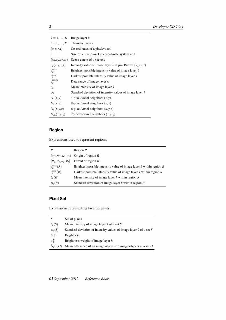
2 Developer XD 2.0.4
k = 1, . . . ,K Image layer k
t = 1, . . . ,T Thematic layer t
(x,y,z, t) Co-ordinates of a pixel/voxel
u Size of a pixel/voxel in co-ordinate system unit
(sx,sy,sz,st) Scene extent of a scene s
ck(x,y,z, t) Intensity value of image layer k at pixel/voxel (x,y,z, t)
cmaxk Brightest possible intensity value of image layer k
cmink Darkest possible intensity value of image layer k
crangek Data range of image layer k
ck Mean intensity of image layer k
σk Standard deviation of intensity values of image layer k
N4(x,y) 4-pixel/voxel neighbors (x,y)
N8(x,y) 8-pixel/voxel neighbors (x,y)
N6(x,y,z) 6-pixel/voxel neighbors (x,y,z)
N26(x,y,z) 26-pixel/voxel neighbors (x,y,z)
Region
Expressions used to represent regions.
R Region R
(xG,yG,zG, tG) Origin of region R
[Rx,Ry,Rz,Rt ] Extent of region R
cmaxk (R) Brightest possible intensity value of image layer k within region R
cmink (R) Darkest possible intensity value of image layer k within region R
ck(R) Mean intensity of image layer k within region R
σk(R) Standard deviation of image layer k within region R
Pixel Set
Expressions representing layer intensity.
S Set of pixels
ck(S) Mean intensity of image layer k of a set S
σk(S) Standard deviation of intensity values of image layer k of a set S
c(S) Brightness
wBk Brightness weight of image layer k
∆k(v,O) Mean difference of an image object v to image objects in a set O
05 September 2012 Reference Book

Introduction 3
Image Object
Expressions representing an image object as a set of pixels.
u,v Image object
O Set of image objects
Pv Set of pixels of an image object v
#Pv Total number of pixels contained in Pv
ck(v) Mean intensity of image layer k forming an image object v
σk(v) Standard deviation of intensity values of image layer k of all pixels forming imageobject v
PInnerv Set of inner border pixels of Pv
POuterv Set of outer border pixels of Pv
vi(P) Image object v in image object level i in pixel P
m(v) Classification of image object v
Bv Bounding box of an image object v
Bv(d) Extended bounding box of an image object v with distance d
xmin(v) Minimum x co-ordinate of v
xmax(v) Maximum x co-ordinate of v
ymin(v) Minimum y co-ordinate of v
ymax(v) Maximum y co-ordinate of v
bv Image object border length
b(v,u) Length of common border between v and u
Image Objects Hierarchy
Expressions used to represent relations between image objects.
u,v Image objects
Uv(d) Superobject of an image object v at a distance d
Sv(d) Sub-objects of an image object v at a distance d
Vi, i = 1, . . . ,n Image object level
Nv Direct neighbors of an image object v
Nv(d) Neighbors of an image object v at a distance d
e(u,v) Neighborhood relation between the image objects u and v
Class-Related Set
Expressions used to represent relations between classes.
Reference Book 05 September 2012

4 Developer XD 2.0.4
M Set of classes M = {m1, . . . ,ma}m A class, (m ∈M)
Nv(d,m) Neighbors classified as m within a distance d
Sv(d,m) Sub-objects classified as m with hierarchical distance d
Uv(d,m) Superobject classified as m with hierarchical distance d
Vi(m) All image objects at level i classified as m
φ(v,m) Fuzzy membership value of image object v to class m
ϕ(v,m) Stored membership value of image object v to class m
Pi(R,m) Pixels classified as m on image object level i within region R
Co-ordinate Systems Used in Definiens Software
Definiens software uses three co-ordinate systems:
• The pixel co-ordinate system is used for identifying pixel positions within a map• The user co-ordinate system allows the use of geocoding information within a map• The internal pixel co-ordinate system is used only for internal calculations by the
Analysis Engine software.
Pixel Co-ordinate System
The pixel co-ordinate system is used to identify pixel position within an image. It is usedfor calculating position features such as x -center and y -center.
This co-ordinate system is oriented from bottom to top and from left to right. The originposition is (0, 0), which is at the bottom-left corner of the image. The co-ordinate isdefined by the offset of the bottom-left corner of the pixel from the origin.
Figure 1. The pixel coordinate system
Pixel Co-ordinate Definition
xmin +1 = xmax ymin +1 = ymax
05 September 2012 Reference Book

Introduction 5
Figure 2. Coordinates of a pixel
User Co-ordinate System
The user co-ordinate system enables the use of geocoding information within a scene. Thevalues of the separate user co-ordinate system are calculated from the pixel co-ordinatesystem. In the user interface, the user co-ordinate system is referred to as the co-ordinatesystem.
This co-ordinate system is defined by geocoding information:
• The bottom-left X position• The bottom-left Y position• Resolution the size of a pixel in co-ordinate system unit. For example, if the co-
ordinate system is metric, the resolution is the size of a pixel in meters. If theco-ordinate system is lat/long, then the resolution is the size of a pixel in degrees
• Co-ordinate system name• Co-ordinate system type.
The origin of the co-ordinate system is at the bottom-left corner of the image (x0,y0) .The co-ordinate defines the position of the bottom-left corner of the pixel within the userco-ordinate system.
Figure 3. The user coordinate system
To convert a value from the pixel co-ordinate system to the user co-ordinate system and
Reference Book 05 September 2012

6 Developer XD 2.0.4
back, the following transformations are valid, where (x,y) are the co-ordinates in userco-ordinate system and u is the pixel size in units:
• x = x0 + xpixel×u• xpixel = (x− x0)/u• y = y0 + ypixel×u• ypixel = (y− y0)/u
Image Layer Related Features
Scene
A scene is a collection of combined input image data, as represented in Definiens software.A scene comprises at least one image layer. In addition, it can include more image layersand thematic layers. You are likely to encounter this concept when importing image orother data into Definiens software.
A scene can also include metadata, such as image creation information or geo-information, and hold settings such as layer aliases, unit information, or geocoding.Within Definiens software, image layers, thematic layers, and metadata are loaded byreference to the respective data files. Each scene is represented by a related map.
• A 2D image in a 3D data set is called a slice.• A 2D image in a time series data set is called a frame.• A 4D data set consists of a series of frames where each frame is a 3D data set.
Depending on the related data set, a scene can be one of the following:
Data Set Scene
2D image A rectangular area in a 2D space
3D data set A rectangular volume in a 3D space
4D data set A series of rectangular volumes in a 4D space
Time series data set A series of rectangular areas in a 2D + time space
Extents
A scene has an origin (x0,y0,z0, t0) , the extent sx in the x -direction, the extent sy in they -direction, the extent sz in the z -direction, and the extent st in the t -direction.
The expression is (sx,sy,sz,st) , where:
• #(pixels)x is the number of pixels in the x -direction• #(pixels)y is the number of pixels in the y -direction• u is the size of a slice pixel in the co-ordinate system unit• uslices is the spatial distance between slices in the co-ordinate system unit• uframes is the temporal distance between slices in the time co-ordinate unit
05 September 2012 Reference Book

Introduction 7
The formulas for scene extent are:
• sx = #(pixels)x×u• sy = #(pixels)x×u• sz = #(slices)×uslices• st = #(frames)×uframes
Co-ordinates
• xpxl is the x offset in pixels• ypxl is the y offset in pixels• zslices is the z offset in slices• tframes is the t offset in frames
Co-ordinate formulas are:
• x = xgeo0 + xpxl×u
• y = ygeo0 + ypxl×u
• z = zgeo0 + zslices×uslices
• t = tgeo0 + tframes×uframes
Figure 4. Coordinates of a multidimensional scene with four slices and three frames
Layers
Scenes can consist of an arbitrary number of image layers (k = 1, ...,K) and thematiclayers (t = 1, ...,T ) .
Maps
A map represents the combination of a scene and an image object hierarchy. It is thestructure that represents the data that the rule set operates on. Definiens software candeal with multiple maps and provides algorithms to rescale and copy maps, as well as tosynchronize image objects between them.
Reference Book 05 September 2012
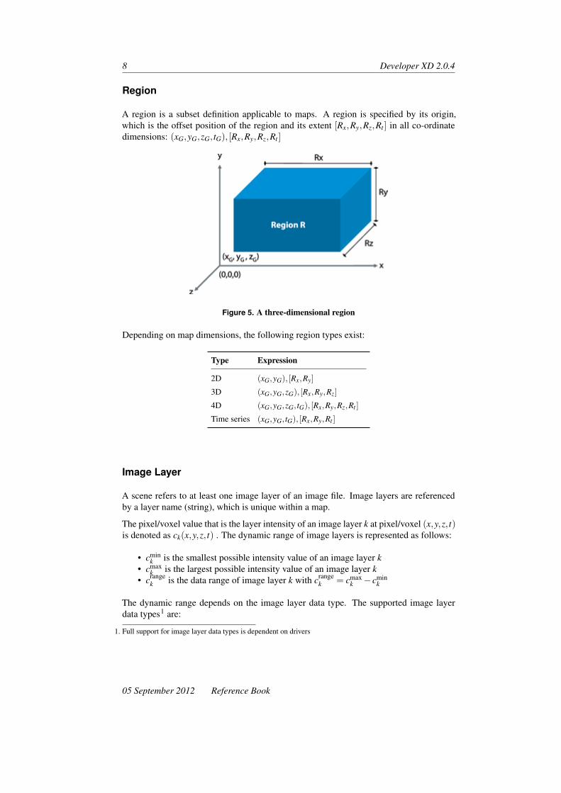
8 Developer XD 2.0.4
Region
A region is a subset definition applicable to maps. A region is specified by its origin,which is the offset position of the region and its extent [Rx,Ry,Rz,Rt ] in all co-ordinatedimensions: (xG,yG,zG, tG), [Rx,Ry,Rz,Rt ]
Figure 5. A three-dimensional region
Depending on map dimensions, the following region types exist:
Type Expression
2D (xG,yG), [Rx,Ry]
3D (xG,yG,zG), [Rx,Ry,Rz]
4D (xG,yG,zG, tG), [Rx,Ry,Rz,Rt ]
Time series (xG,yG, tG), [Rx,Ry,Rt ]
Image Layer
A scene refers to at least one image layer of an image file. Image layers are referencedby a layer name (string), which is unique within a map.
The pixel/voxel value that is the layer intensity of an image layer k at pixel/voxel (x,y,z, t)is denoted as ck(x,y,z, t) . The dynamic range of image layers is represented as follows:
• cmink is the smallest possible intensity value of an image layer k
• cmaxk is the largest possible intensity value of an image layer k
• crangek is the data range of image layer k with crange
k = cmaxk − cmin
k
The dynamic range depends on the image layer data type. The supported image layerdata types1 are:
1. Full support for image layer data types is dependent on drivers
05 September 2012 Reference Book

Introduction 9
Type cmink cmax
k crangek
8-bit unsigned (int) 0 255 256
16-bit unsigned (int) 0 65535 65536
16-bit signed (int) −32767 32767 65535
32-bit unsigned (int) 0 4294967295 4294967296
32-bit signed (int) −2147483647 2147483647 4294967295
32-bit float 1.17 × 10 − 38 3.40 × 1038 n/a
The mean value of all pixel/voxels in a layer is computed by:
ck =1
sx× sy ∑(x,y)
ck(x,y)
The standard deviation of all pixel/voxels in a layer is computed by:
σk =
√√√√ 1sx× sy
(∑(x,y)
(ck(x,y)
)2− 1sx× sy ∑
(x,y)ck(x,y) ∑
(x,y)ck(x,y)
)
Neighborhood
On raster pixel/voxels there are two ways to define the neighborhood: as 6-neighborhoodor 26-neighborhood.
Image Layer Intensity on Pixel Sets
A fundamental measurement on a pixel set S and an image object v is the distribution ofthe layer intensity. Firstly, the mean intensity within the set is defined by:
ck(S) =1#s ∑
(x,y)∃Sck(x,y)
The standard deviation is defined as:
σk(S) =
√√√√ 1#S
(∑
(x,y)∃S(ck(x,y))2− 1
#S ∑(x,y)∃S
ck(x,y) ∑(x,y)∃S
ck(x,y))
An overall intensity measurement is given by the brightness which is the mean value ofck(S) for selected image layers.
c(S) =1
wB
K
∑k=1
wBk ck(S)
If v is an image object and O a set of other image objects, then the mean difference of theobjects within O to an image object v is calculated by:
∆k(v,0) =1w ∑
uε0wu(ck(v)− ck(u)
)
Reference Book 05 September 2012

10 Developer XD 2.0.4
Image Object Related Features
Image Object
An image object is a set of pixels. The set of pixels of an image object v is denoted as Pv.
Image Object Size
At a basic level, the size of an image object is measured by the number of pixels in imageobject v. The number of pixels is denoted by #Pv , the cardinality of the respective pixelset.
Bounding Box of an Image Object
The bounding box Bv of an image object v is the most common form of measurementof the extent of an image in a scene. It is the smallest rectangular area that encloses allpixels of v along x- and y-axes. The bounding box is therefore defined by the minimumand maximum values of the x and y co-ordinates of an image object v
(xmin(v) , xmax(v)
and ymin(v) , ymax(v))
.
The extended bounding box Bv(d) is created by enlarging the bounding box with the samenumber of pixels in all directions.
Figure 6. Bounding box of an image object v
Pixel Neighborhood and Connectivity of Image Objects
Two pixels are considered to be spatially connected if they neighbor each other in thepixel raster. On 2D raster images, the neighborhood between pixels can be defined as a4- or 8-neighborhood:
With reference to the green pixel, the light-blue pixels are the 4-neighborhood. In combi-nation with the dark blue pixels, they form the 8- or diagonal neighborhood of the greenpixel. Definiens software uses the 4-neighborhood for all spatial neighborhood calcula-tions. As it assumes Image objects to be a set of spatially connected pixels, an image
05 September 2012 Reference Book

Introduction 11
Figure 7. 4- and 8-neighborhoods
object is defined as connected if it is connected according to the 4-neighborhood princi-ple.
Neighborhood Relations Between Image Objects
Two image objects are considered neighbors if they contain pixels that neighbor eachother according to the 4-neighborhood principle. In other words, two image objects uand v are considered neighboring each other if this is at least on pixel (x,y) ∈ Pv andone pixel (x′,y′) ∈ Pu so that (x′,y′) is part of N4(x,y) . The set of all image objectsneighboring v is denoted by Nv(d) :
Nv = {u ∈Vi : ∃(x,y) ∈ Pv∃(x′,y′) ∈ Pu : (x′,y′)∃N4(x,y)}
Figure 8. Neighborhood relation
The entire border line between u and v is called the neighborhood relation and is repre-sented as {$e(u,v).$ The neighborhood relations between image objects are automaticallydetermined and maintained by the Definiens software.
Border of an Image Object
The border length bv of a two-dimensional image object v is calculated by the number ofthe elementary pixel borders. The border length of a three-dimensional image object iscalculated from the borders of image object slices multiplied by the slice distance. Theborder of image object slices is counted by the number of the elementary pixel borders.
Similarly, the border length b(v,u) of the neighborhood relation between two image ob-jects v and u is calculated from the common borders of image object slices multiplied
Reference Book 05 September 2012

12 Developer XD 2.0.4
by the slice distance. The border of image object slices is counted by the number of theelementary pixel borders along the common border. Image objects are basically pixelsets. The number of pixels belonging to an image object v and its pixel set Pv is denotedby #Pv .
Figure 9. Border length of an image object v or between two objects v , u
Inner Border The set of all pixels in Pv belonging to the inner border pixels of an imageobject v is defined by PInner
v with PInnerv = {(x,y) ∈ Pv : ∃(x′,y′) ∈ N4(x,y) : (x′,y′) /∈ Pv}
Figure 10. Inner and outer borders of an image object
Outer Border The set of all pixels in Pv belonging to the outer border pixels of an imageobject v is defined by POuter
v with POuterv = {(x,y) /∈ Pv : ∃(x′,y′) ∈ N4(x,y) : (x′,y′) ∈ Pv}
Neighborhood Relations of 3D Image Objects RfB
Image objects in Definiens Developer XD 2.0.4 can be two-dimensional or three-dimensional. The two-dimensional neighborhood concept can be easily extended to threedimensions. That is, for 3D image objects, there is a 6-neighborhood resulting from thetwo additional neighboring pixels in the z dimension. This diagonal 3D neighborhood isalso referred to as the 26-neighborhood.
3D objects are usually 6-connected and may extend across several slices. Several sepa-rated parts within a single slice are also possible. However, these parts must be connectedalong parts of other slices. If you look at a 3D object in the map view using one of thethree 2D projections, a two-dimensional slice is displayed on the plane. You can use theMPR view or the 3D view to get a better impression of the shape of a 3D image object.
05 September 2012 Reference Book

Introduction 13
The software manages two- and three-dimensional neighborhood relations separately.This allows a correct determination of neighborhood relations in mixed mode situationswhere 2D and 3D image objects co-exist in the same scene. 2D image objects can onlybe connected by two-dimensional neighborhood relations while 3D image objects can beconnected by both two-dimensional and three-dimensional neighborhood relations.
Figure 11. 2D and 3D neighborhood relations
Tracking Image Objects Through Time
There is no special image object type to represent the movement of an image object intime. Instead, image object links are used to track identical image objects at differentpoints in time (a time series).
Disconnected Image Objects
In addition to normal 2D and 3D image objects, Definiens Developer XD 2.0.4 allowsyou to work with image objects that are spatially disconnected. While a connected imageobject covers one contiguous region of a scene, a disconnected image object can consistof arbitrary pixels in two or more potentially disconnected parts within a scene.
It is important to know that image objects can be defined as disconnected even thoughthey are not disconnected in reality. An image object is defined as disconnected if it lacksinformation about its spatial connectivity. The major motivation for this lack of informa-tion is the high calculation effort that is necessary to ensure spatial connectivity. If, forexample, you remove some pixels from an image object, it may divide into several parts.To connect the resulting image objects, a special algorithm needs to analyze the remain-ing objects and separate them properly into several sub-image objects. If the resultingimage objects remain disconnected, they can be simply marked as there is no need for an
Reference Book 05 September 2012

14 Developer XD 2.0.4
analysis. Disconnected image objects are therefore useful for fast object processing whenspatial information is not relevant. If you use threshold segmentation, for example, to sep-arate an image into two disconnected image objects, you can save a lot of computing timeand memory since the number of image objects is considerably reduced.
Figure 12. Disconnected image objects (left) and spatially connected image object (right)
The main purpose of working with disconnected image objects is the representation ofsimple “pixel crowds”, where several properties that can be measured for normal imageobjects might not make sense or are meaningless. You should therefore note that thefollowing information is not available for disconnected image objects:
• Neighborhood relations and all features based on these relations• Shape features• Polygons.
Image Object Hierarchy
Image objects are organized into levels, where each object on each level creates a partitionof the scene S . This can be described using the following fundamental conditions. Thetotality of all image objects covers the entire scene:
Uv∃Vi
Pv = {(x,y)}
There are no image objects that overlap (having a non-empty intersection):
∀u,v∃Vi
Pu∩Pv = ∅
The image object levels are hierarchically structured. This means that all image objectson a lower level are complete contained in exactly one image object of a higher level.
∀i< j
∀v∃Vi
∃u∃Vi
Pv ⊂ Pu
05 September 2012 Reference Book

Introduction 15
Level Distance
The level distance represents the hierarchical distance between image objects on differentlevels in the image object hierarchy. Starting from the current image object level, thelevel distance indicates the hierarchical distance of image object levels containing therespective image objects (sub-objects or superobjects).
Since each object has exactly 1 or 0 superobjects on the higher level, the superobject ofv with a level distance d can be denoted as Uv(d). Similarly, all sub-objects with a leveldistance d are denoted as Sv(d).
Figure 13. Image object hierarchy
Spatial Distance
The spatial distance represents the distance between image objects on the same level inthe image object hierarchy. If you want to analyze neighborhood relations between imageobjects on the same image object level in the image object hierarchy, the feature distanceexpresses the spatial distance (in pixels) between the image objects. The default value is0 (in other words, only neighbors that have a mutual border are considered). The set ofall neighbors within a distance d are denoted by Nv(d).
Distance Measurements Many features enable you to enter a spatial distance parameter.Distances are usually measured in pixel units. Because exact distance measurements be-tween image objects are very processor-intensive, Definiens software uses approximationapproaches to estimate the distance between image objects.
There are two different approaches: the center of gravity and the smallest enclosing rect-angle. You can configure the default distance calculations.
Center of Gravity The Center of Gravity approximation measures the distance betweenthe center of gravity between two image objects. This measure can be computed veryefficiently but it can be inaccurate for large image objects.
Reference Book 05 September 2012

16 Developer XD 2.0.4
Smallest Enclosing Rectangle The smallest enclosing rectangle approximation tries tocorrect the center of gravity approximation by using rectangular approximations of theimage object to adjust the basic measurement delivered by the center of gravity.
Figure 14. Distance calculation between image objects. (The black line is the center of gravityapproximation. The red line is the smallest enclosing rectangle approximation)
We recommend using the center of gravity distance for most applications although thesmallest enclosing rectangle may give more accurate results. A good strategy for exactdistance measurements is to use center of gravity and try to avoid large image objects, forexample, by creating border objects. To avoid performance problems, restrict the totalnumber of objects involved in distance calculations to a small number.
You can edit the distance calculation in the algorithm parameters of the Set Rule SetOptions algorithm and set the Distance Calculation option to your preferred value.
Class-Related Features
Class-Related Sets
Let M = {m1, . . . ,ma} be a set of classes with m being a specific class and m ∈M. Eachimage object has a fuzzy membership value of φ(v,m) to class m . In addition eachimage object also carries the stored membership value ϕ(u,m) that is computed duringexecution of the last classification algorithm. By restricting a set of image objects Oto only the image object that belong to class m , various class-related features can becomputed:
Nv(d,m) = {u ∈ Nv(d) : ϕ(u,m) = 1} Neighbors of class
Sv(d,m) = {u ∈ Sv(d) : ϕ(u,m) = 1} Sub-objects of class
Uv(d,m) = {u ∈Uv(d) : ϕ(u,m) = 1} Superobjects of class
Vi(m) = {u ∈Vi(m) : ϕ(u,m) = 1} Image object levels of class
Pi(R,m) = {p ∈ R : (vi(p)) = m} Pixels of class
Example: The mean difference of layer k to a neighbor image object within a distance dand that image object belongs to a class m is defined as ∆k(v,Nv(d,m)).
05 September 2012 Reference Book

Introduction 17
Shape-Related Features
Many of the Definiens form features are based on the statistics of the spatial distributionof the voxels that form an 3D image object. As a central tool to work with these statistics,Definiens Developer XD 2.0.4 uses the covariance matrix:
Parameters
• X : x co-ordinates of all voxels forming the image object• Y : y co-ordinates of all voxels forming the image object• Z : z co-ordinates of all voxels forming the image object.
Expression
C =
Var(X) Cov(XY ) Cov(XZ)Cov(XY ) Var(Y ) Cov(Y Z)Cov(XZ) Cov(Y Z) Var(Z)
Another frequently used technique to derive information about the form of image objectsis the bounding box approximation. Such a bounding box can be calculated for eachimage object and its geometry can be used as the first clue to the image object itself.
The main information provided by the bounding box is its length a , its width b , itsthickness c , its volume a×b×c and its degree of filling f , which is the volume V filledby the image object divided by the total volume a×b× c of the bounding box.
Shape Approximations Based on Eigenvalues
The shape approximations based on eigenvalues measures the statistical distribution ofthe voxel co-ordinates (x,y,z) of a set Pv .
The center of gravity of the set Pv is:
xcenter =1
#Pv∑
(x,y,z)x
ycenter =1
#Pv∑
(x,y,z)y
zcenter =1
#Pv∑
(x,y,z)z
The variances of voxel co-ordinates are:
Cxx =1
#Pv∑
(x,y,z)x2
i −(
1#P v
∑(x,y,z)
xi
)2
= Exx−E2x
Cyy =1
#Pv∑
(x,y,z)y2
i −(
1#P v
∑(x,y,z)
yi
)2
= Eyy−E2y
Reference Book 05 September 2012

18 Developer XD 2.0.4
Czz =1
#Pv∑
(x,y,z)y2
i −(
1#P v
∑(x,y,z)
yi
)2
= Ezz−E2z
Cxy =1
#Pv∑
(x,y,z)xiyi−
(1
#Pv∑
(x,y,z)xi
)×(
1#Pv
∑(x,y,z)
yi
)= Exy−ExEy
Cxz =1
#Pv∑
(x,y,z)xizi−
(1
#Pv∑
(x,y,z)xi
)×(
1#Pv
∑(x,y,z)
zi
)= Exz−ExEz
Cyz =1
#Pv∑
(x,y,z)yizi−
(1
#Pv∑
(x,y,z)yi
)×(
1#Pv
∑(x,y,z)
zi
)= Eyz−EyEz
The covariance matrix C of voxel co-ordinates is:
C =
Cxx Cxy Cxz
Cyx Cyy Cyz
Czx Czy Czz
The diagonalization of the covariance matrix gives three eigenvalues (λ1,λ2,λ3) , whichare the main, medium, and minor axes of an ellipsoid.
λ× e = C× e , where λ is the eigenvalue and e is the eigenvector.
Elliptic Approximation
The elliptic approximation uses the eigenvalues (λ1,λ2,λ3) of the covariance matrix andcomputes an ellipsis with axis along the eigenvector e1 with length a , and along theeigenvector e2 with length b , and along the eigenvector e3 with length c .
The formula is a : b : c = λ1 : λ2 : λ3 .
Figure 15. Elliptic approximation
05 September 2012 Reference Book

Introduction 19
About Algorithms
A single process executes an algorithm on an image object domain. It is the elementaryunit of a rule set and provides a solution to a specific image analysis problem. Processesare the main working tools for developing rule sets. A rule set is a sequence of processesthat are executed in a defined order.
The image object domain is a set of image objects. Every process loops through this setof image objects one by one and applies the algorithm to each single image object. Thisimage object is referred to as the current image object.
Creating a Process
A single process can be created using the Edit Process dialog box, in which you candefine:
• The method of the process from an algorithm list, for example MultiresolutionSegmentation or Classification
• The image object domain on which an algorithm should be performed• Detailed algorithm parameter settings.
Figure 16. The Edit Process dialog box
Specifying Algorithm Parameters
Depending on the chosen algorithm, several parameters may be modified:
1. Define the individual settings of the algorithm in the Algorithms Parameters groupbox. If available, click a plus sign (+) button to expand the table to access additionalparameters.
Reference Book 05 September 2012

20 Developer XD 2.0.4
2. To edit values of parameters, select the parameter name or its value by clicking onit. Depending on the type of value, change the value in one of the following ways:
• Edit values directly within the value field.• Click the ellipsis button located inside the value field. A dialog box opens,
enabling you to configure the value.• Select the value from a drop-down list. For many parameters, you can select
a feature by clicking the From feature item. or an existing variable. Alterna-tively, you can select a variable. To create a new variable, type a name for thenew variable and click OK, or press Enter to open the Create Variable dialogbox for additional settings.
05 September 2012 Reference Book

1 Process-Related OperationAlgorithms
The Process-Related Operation algorithms are used to control other processes.
1.1 Execute Child Processes
Execute all child (subordinate) processes of a process. To define a process using thisalgorithm as a parent process, you can right-click it and choose the Insert Child commandin the context menu.
1.1.1 Supported Domains
Execute
Use the Execute Child Processes algorithm in conjunction with the Execute domain tostructure your process tree. A process with this setting serves as a parent process, provid-ing a container for a sequence of functionally related child processes.
Pixel Level
Applies the algorithm at the pixel level. Typically used for initial segmentations.
Image Object Level
Use the Execute Child Processes algorithm in conjunction with other image object do-mains (for example, the image object level domain) to loop over a set of image objects.All contained child processes will be applied to the image objects in the image objectdomain. In this case the child processes usually use one of the following as image objectdomain: current image object, neighbor object, super object, sub objects.
Current Image Object
Applies the algorithm to the current internally selected image object of the parent process.
21

22 Developer XD 2.0.4
Neighbor Image Object
Applies the algorithm to all neighbors of the current internally selected image object ofthe parent process. The size of the neighborhood is defined by the Distance parameter.
Super Object
Applies the algorithm to the superobject of the current internally selected image objectof the parent process. The number of levels above in the image object level hierarchy isdefined by the Level Distance parameter.
Sub Object
Applies the algorithm to the sub objects of the current internally selected image objectof the parent process. The number of levels below in the image object level hierarchy isdefined by the Level Distance parameter.
Maps
Applies the algorithm to all specified maps of a project. You can select this domain inparent processes with the Execute Child Process algorithm to set the context for childprocesses that use the map parameter From Parent.
Linked Objects
Applies the algorithm to all linked image objects of the current internally selected imageobject of the parent process.
Image Object List
Applies the algorithm to all image objects that were collected with the algorithm UpdateImage Object List.
Array
Options for the array function are visible when Array is selected as the Image ObjectDomain (for information on using arrays, please consult the user guide):
• Array: Select a predefined array• Array Type: Displays the array type (this is not editable)• Variable: The variable holding the value of the current array item when the process
is executed• Index Variable: The scene variable holding the index of the current array item
when the process is executed
05 September 2012 Reference Book

Process-Related Operation Algorithms 23
1.2 Execute Child As Series
When items are exported during a multimap analysis they are held in memory, which canoften lead to out-of-memory problems during intensive analyses. The Execute Child asSeries algorithm allows partial results to be exported as soon as they are available, freeingup memory for other tasks.
1.2.1 Supported Domains
Execute; Image Object Level; Current Image Object; Neighbor Image Object; Sub Ob-ject; Super Object; Linked Objects; Maps; Image Object List
1.2.2 Algorithm Parameters
Series Name
Enter the series name variables and strings are possible. All export algorithms receive anew parameter: Export Series (Yes/No)
1.3 If, Then and Else
If the conditions in the If algorithm are connected, all the defined conditions must be trueto enter the Then path, otherwise the Else path is taken
• If no condition is defined, the Then path is chosen• If there is more than one Then or Else condition, all are executed.
1.3.1 Supported Domains
Execute; Pixel Level; Image Object Level; Current Image Object; Neighbor Image Ob-ject; Super Object; Sub Objects; Linked Objects; Maps; Image Object List; Array
1.4 Throw
The Throw algorithm generates an error message (the Exception Message parameter) if acertain condition occurs, for example the number of objects exceeds a defined number.
1.4.1 Supported Domains
Execute; Pixel Level; Image Object Level: Current Image Object; Neighbor Image object;Super Object; Sub Objects; Linked Objects; Maps; Image Object List; Array
Reference Book 05 September 2012

24 Developer XD 2.0.4
1.5 Catch
If an exception (generating an error message) occurs as defined in the Throw algorithmand a Catch algorithm has been defined, the error message is not generated. Instead theprocesses (and any child processes) defined in the Catch algorithm are executed. If thereare Catch processes without an exception, the Catch process is not executed.
1.5.1 Supported Domains
Execute; Pixel Level; Image Object Level: Current Image Object; Neighbor Image object;Super Object; Sub Objects; Linked Objects; Maps; Image Object List; Array
1.6 Set Rule Set Options
The Set Rule Set Options algorithm lets you control certain settings for the rule set, orparts of rule sets. For example, you may want to apply particular settings to analyze largeobjects and change them to analyze small objects. In addition, because the settings arepart of the rule set and not on the client, they are preserved when the rule set is run on aserver.
You can save the rule set or the associated project to preserve the settings chosen in thisalgorithm, because saving the project also saves the rule set. The current settings displayunder Project Settings in the Options dialog box.
1.6.1 Supported Domains
Execute
1.6.2 Algorithm Parameters
Apply to Child Processes Only
If the value is No, settings apply globally, persisting after completion of execution. If Yesis selected, changes apply only to child processes.
Distance Calculation
• Smallest Enclosing Rectangle uses the smallest enclosing rectangle of an imageobject for distance calculations
• Center of Gravity uses the center of gravity of an image object for distance calcu-lations
• Default reverts values to their defaults when the rule set is saved• Keep Current maintains the existing settings when the rule set is saved
05 September 2012 Reference Book

Process-Related Operation Algorithms 25
Current Resampling Method
• Center of Pixel initiates resampling from the center of the pixel.• Upper Left Corner of Pixel initiates resampling from the upper-left corner of the
pixel.• Default reverts values to their defaults when the rule set is saved• Keep Current maintains the existing settings when the rule set is saved
Evaluate Conditions on Undefined Features as 0
When a value is undefined, with respect to a condition you have specified, the softwarecan evaluate it as false, or perform the evaluation based on a value of zero.
• Yes: Evaluate any condition with undefined feature as “false” (this is the default).• No: Assign value “zero” to undefined feature before evaluation of any condition
with undefined feature.• Default reverts values to their defaults when the rule set is saved• Keep Current maintains the existing settings when the rule set is saved.
Polygons Base Polygon Threshold
This value sets the degree of abstraction for the base polygons. The default is 1.25.
Polygons Shape Polygon Threshold
This value determines the degree of abstraction for the shape polygons. Shape polygonsare independent of the topological structure and consist of at least three points. Thethreshold for shape polygons can be changed any time without the need to recalculate thebase vectorization. The default value is one.
Polygons Remove Slivers
Remove Slivers is used to avoid intersection of edges of adjacent polygons and self-intersections of polygons.
Sliver removal becomes necessary with higher threshold values for base polygon genera-tion. Note that the processing time to remove slivers is high, especially for low thresholdswhere it is not needed anyway.
• No enables the intersection of polygon edges and self-intersections• Yes avoids the intersection of edges of adjacent polygons and self-intersections of
polygons• Default reverts values to their defaults when the rule set is saved• Keep Current maintains the existing settings when the rule set is saved
Update Topology
Update Topology allows you to update neighborhood relations automatically or on de-mand.
Reference Book 05 September 2012

26 Developer XD 2.0.4
Save Temporary Layers
Selecting Yes saves temporary layers to your hard drive. The default layer values inDefiniens Developer XD 2.0.4 are:
• Yes for new rule sets.• No for rule sets created with Definiens Enterprise Image Intelligence 7 or earlier.• Yes for rule sets created with Definiens XD 1
Polygon Compatibility Mode
Set this option to use polygon compatibility option for polygons.
05 September 2012 Reference Book

2 Segmentation Algorithms
Segmentation algorithms are used to subdivide entire images at a pixel level, or specificimage objects from other domains into smaller image objects.
Definiens provides several different approaches to segmentation, ranging from very sim-ple algorithms, such as chessboard and quadtree-based segmentation, to highly sophisti-cated methods such as multiresolution segmentation and contrast filter segmentation.
Segmentation algorithms are required whenever you want to create new image objectslevels based on image layer information. But they are also a very valuable tool to refineexisting image objects by subdividing them into smaller pieces for more detailed analysis.
2.1 Chessboard Segmentation
The Chessboard Segmentation algorithm splits the pixel domain or an image object do-main into square image objects.
A square grid aligned to the image left and top borders of fixed size is applied to allobjects in the domain and each object is cut along these gridlines.
Figure 2.1. Result of chessboard segmentation with object size 20
27

28 Developer XD 2.0.4
2.1.1 Supported Domains
Pixel Level; Image Object Level: Current Image Object; Neighbor Image Object; SuperObject; Sub Objects; Linked Objects; Image Object List
2.1.2 Algorithm Parameters
Object Size
Object Size defines the size of the square grid in pixels. Variables are rounded to thenearest integer
Level Name
In the Level Name field, enter the name of a new image object level. This parameter isonly available, if the domain Pixel Level is selected in the process dialog.
Overwrite Existing Level
This parameter is only available when Pixel Level is selected. It allows you to automati-cally delete an existing image level above the pixel level and replace it with a new levelcreated by the segmentation.
Thematic Layer Usage
In the Thematic Layers field, specify the thematic layers to be considered in additionto segmentation. Each thematic layer used for segmentation will cause further splittingof image objects while enabling consistent access to its thematic information. You cansegment an image using more than one thematic layer. The results are image objects rep-resenting proper intersections between the thematic layers. If you want to produce imageobjects based exclusively on thematic layer information, you can select a chessboard sizelarger than your image size.
2.2 Quadtree-Based Segmentation
The Quadtree-Based Segmentation algorithm splits the pixel domain or an image objectdomain into a quadtree grid formed by square objects.
A quadtree grid consists of squares with sides each having a power of two and alignedto the image left and top borders. It is applied to all objects in the domain and eachobject is cut along these gridlines. The quadtree structure is built so that each square hasa maximum possible size and also fulfills the homogeneity criteria defined by the modeand scale parameters.
The maximum square object size is 256 x 256, or 65,536 pixels.
05 September 2012 Reference Book

Segmentation Algorithms 29
Figure 2.2. Result of quadtree-based segmentation with mode color and scale 40
2.2.1 Supported Domains
Pixel Level; Image Object Level: Current Image Object; Neighbor Image Object; SuperObject; Sub Objects; Linked Objects; Image Object List
2.2.2 Algorithm Parameters
Mode
• Color: The maximal color difference within each square image object is less thanthe Scale value
• Super Object Form: Each square image object must completely fit into the super-object. This mode only works with an additional upper image level
Scale
Scale defines the maximum color difference within each selected image layer insidesquare image objects. It is only used in conjunction with the Color mode.
Level Name
In the Level Name field, enter the name of a new image object level. This parameter isonly available if the domain Pixel Level is selected in the process dialog.
Overwrite Existing Level
This parameter is only available when Pixel Level is selected. It allows you to automati-cally delete an existing image level above the pixel level and replace it with a new levelcreated by the segmentation.
Reference Book 05 September 2012

30 Developer XD 2.0.4
Image Layer Weights
Image layers can be weighted depending on their importance or suitability for the seg-mentation result. The higher the weight assigned to an image layer, the more weightwill be assigned to that layer’s pixel information during the segmentation process, if it isused. Consequently, image layers that do not contain the information intended for repre-sentation by the image objects should be given little or no weight. For example, whensegmenting a geographical LANDSAT scene using multiresolution segmentation or spec-tral difference segmentation, the segmentation weight for the spatially coarser thermallayer should be set to 0 in order to avoid deterioration of the segmentation result by theblurred transient between image objects of this layer.
1. In the Algorithm parameters area, expand the Image Layer weights list and set theweight of the image layers to be considered by the algorithm. You can use both ofthe following methods:
• Select an image layer and edit the weight value• Select Image Layer weights and click the ellipsis button located inside the
value field to open the Image Layer Weights dialog box2. Select an image layer in the list. To select multiple image layers press Ctrl.3. Enter a new weight in the New value text box and click Apply.
Figure 2.3. Image Layer Weights dialog box
Options
• Click the Calculate Stddev button to check the image layer dynamics. The calcu-lated standard deviations of the image layer values for each single image layer arelisted in the Stddev. column.
• To search for a specific layer, type the name into the Find text box.
05 September 2012 Reference Book

Segmentation Algorithms 31
2.2.3 Thematic Layer Weights
In the Thematic Layers field, specify the thematic layers to be considered in addition tosegmentation. Each thematic layer used for segmentation will cause additional splittingof image objects while enabling consistent access to its thematic information. You cansegment an image using more than one thematic layer. The results are image objects rep-resenting proper intersections between the thematic layers. If you want to produce imageobjects based exclusively on thematic layer information, you can select a chessboard sizelarger than your image size between the thematic layers.
2.3 Contrast Split Segmentation
The Contrast Split Segmentation algorithm segments an image or image object into darkand bright regions. It is based on a threshold that maximizes the contrast between theresulting bright objects (consisting of pixels with pixel values above the threshold) anddark objects (consisting of pixels with pixel values below the threshold).
The algorithm evaluates the optimal threshold separately for each image object in the im-age object domain. If the pixel level is selected in the image object domain, the algorithmfirst executes a chessboard segmentation, then performs the split on each square.
It achieves the optimization by considering different pixel values as potential thresholds.The test thresholds range from the minimum threshold to the maximum threshold, withintermediate values chosen according to the step size and stepping type parameter. Ifa test threshold satisfies the minimum dark area and minimum bright area criteria, thecontrast between bright and dark objects is evaluated. The test threshold causing thelargest contrast is chosen as the best threshold and used for splitting.
2.3.1 Supported Domains
Pixel Level; Image Object Level: Current Image Object; Neighbor Image Object; SuperObject; Sub Objects; Linked Objects; Image Object List
2.3.2 Settings
Chessboard Tile Size
This field is available only if pixel level is selected in the Image Object Domain. Enterthe chessboard tile size (the default is 1,000).
Level Name
Select or enter the level to contain the results of the segmentation. Available only if thepixel level is in the image object domain.
Reference Book 05 September 2012

32 Developer XD 2.0.4
Overwrite Existing Level
This parameter is only available when Pixel Level is selected. It allows you to automati-cally delete an existing image level above the pixel level and replace it with a new levelcreated by the segmentation.
Minimum Threshold
Enter the minimum gray value to be considered for splitting. The algorithm calculates thethreshold for gray values from the minimum threshold value to the maximum thresholdvalue (the default is 0).
Maximum Threshold
Enter the maximum gray value to be considered for splitting. The algorithm calculates thethreshold for gray values from the minimum threshold value to the maximum thresholdvalue (the default is 255).
Step Size
Enter the step size by which the threshold increases from the minimum threshold to themaximum threshold. The value is either be added to the threshold or multiplied by thethreshold, according to the selection in the Stepping Type field. The algorithm recalcu-lates a new best threshold each time the threshold is changed by application of the valuesin the Step Size and Stepping Type fields, until the maximum threshold is reached. Highervalues entered for step size tend to execute more quickly; smaller values tend to achievea split with a larger contrast between bright and dark objects.
Stepping Type
Use the drop-down list to select one of the following:
• Add: Calculate each step by adding the value in the Scan Step field• Multiply: Calculate each step by multiplying by the value in the Scan Step field
Image Layer
Select the image layer where the contrast is to be maximized.
Class for Bright Objects
Create a class for image objects brighter than the threshold or select one from the drop-down list. Image objects are not classified if the value in the Execute splitting field isNo.
05 September 2012 Reference Book

Segmentation Algorithms 33
Class for Dark Objects
Create a class for image objects darker than the threshold or select one from the drop-down list. Image objects are not classified if the value in the Execute splitting field isNo.
2.3.3 Advanced Settings
Contrast Mode
Select the method the algorithm uses to calculate contrast between bright and dark objects.The algorithm calculates possible borders for image objects (where a is the mean of brightborder pixels and b is the mean of dark border pixels):
• Edge Ratio: (a−b)÷ (a+b)• Edge Difference: (a−b)• Object Difference: The difference between the mean of all bright pixels and the
mean of all dark pixels.
Execute Splitting
Select Yes to split objects with the best-detected threshold. Select No to simply computethe threshold without splitting.
Variable for Best Threshold
Enter a scene variable to store the computed pixel value threshold that maximizes thecontrast.
Variable for Best Contrast
Enter a scene variable to store the computed contrast between bright and dark objectswhen splitting with the best threshold. The computed value is different for each contrastmode.
Minimum Relative Area Dark
Enter the minimum relative dark area. Segmentation into dark and bright objects onlyoccurs if the relative dark area is higher than the value entered. Only thresholds thatlead to a relative dark area larger than the value entered are considered as best thresholds.Setting this value to a number greater than 0 may increase speed of execution.
Minimum Relative Area Bright
Enter the minimum relative bright area. Only thresholds that lead to a relative bright arealarger than the value entered are considered as best thresholds. Setting this value to anumber greater than 0 may increase speed of execution.
Reference Book 05 September 2012

34 Developer XD 2.0.4
Minimum Contrast
Enter the minimum contrast value threshold. Segmentation into dark and bright objectsonly occurs if a contrast higher than the value entered can be achieved.
Minimum Object Size
Enter the minimum object size in pixels that can result from segmentation. Only largerobjects are segmented. Smaller objects are merged with neighbors randomly. (The defaultvalue of 1 effectively inactivates this option.)
2.4 Multiresolution Segmentation
The Multiresolution Segmentation algorithm locally minimizes the average heterogeneityof image objects for a given resolution of image objects. It can be executed on an existingimage object level or the pixel level for creating new image objects on a new image objectlevel.
Figure 2.4. Result of multiresolution segmentation with scale 10, shape 0.1 and compactness0.5
The multiresolution segmentation algorithm consecutively merges pixels or existing im-age objects. Thus it is a bottom-up segmentation algorithm based on a pairwise regionmerging technique. Multiresolution segmentation is an optimization procedure which,for a given number of image objects, minimizes the average heterogeneity and maximizestheir respective homogeneity.
The segmentation procedure works according the following rules, representing a mutual-best-fitting approach:
1. The segmentation procedure starts with single image objects of one pixel and re-peatedly merges them in several loops in pairs to larger units as long as an upperthreshold of homogeneity is not exceeded locally. This homogeneity criterion isdefined as a combination of spectral homogeneity and shape homogeneity. You
05 September 2012 Reference Book

Segmentation Algorithms 35
can influence this calculation by modifying the scale parameter. Higher values forthe scale parameter result in larger image objects, smaller values in smaller imageobjects.
2. As the first step of the procedure, the seed looks for its best-fitting neighbor for apotential merger.
3. If best fitting is not mutual, the best candidate image object becomes the new seedimage object and finds its best fitting partner.
4. When best fitting is mutual, image objects are merged.5. In each loop, every image object in the image object level will be handled once.6. The loops continue until no further merger is possible.
Figure 2.5. Each image object uses the homogeneity criterion to determine the best neighborto merge with
Figure 2.6. If the first image object’s best neighbor (red) does not recognize the first imageobject (gray) as best neighbor, the algorithm moves on (red arrow) with the second imageobject finding the best neighbor
Figure 2.7. This branch-to-branch hopping repeats until mutual best fitting partners arefound
The procedure continues with another image object’s best neighbor. The procedure iter-ates until no further image object mergers can be realized without violating the maximumallowed homogeneity of an image object.
With any given average size of image objects, multiresolution segmentation yields goodabstraction and shaping in any application area. However, it has higher memory require-ments and significantly slower performance than some other segmentation techniques andtherefore is not always the best choice.
Reference Book 05 September 2012

36 Developer XD 2.0.4
Figure 2.8. If the homogeneity of the new image object does not exceed the scale parameter,the two partner image objects are merged.
2.4.1 Supported Domains
Pixel level; Image Object Level
2.4.2 Level Settings
Level Name
The Level Name field lets you define the name for the new image object level. It is onlyavailable if a new image object level will be created by the algorithm. To create newimage object levels, use either the image object domain pixel level in the process dialogor set the Level Usage parameter to Create Above or Create Below.
Overwrite Existing Level
This parameter is only available when Pixel Level is selected. It allows you to automati-cally delete an existing image level above the pixel level and replace it with a new levelcreated by the segmentation.
Level Usage
Select one of the available modes from the drop-down list. The algorithm is appliedaccording to the mode based on the image object level that is specified by the imageobject domain. This parameter is not visible if pixel level is selected as image objectdomain in the Edit Process dialog box.
• Use Current applies multiresolution segmentation to the existing image object level.Objects can be merged and split depending on the algorithm settings
• Use Current (Merge Only) applies multiresolution segmentation to the existing im-age object level. Objects can only be merged. Usually this mode is used togetherwith stepwise increases of the scale parameter
• Create Above creates a copy of the image object level as super objects• Create Below creates a copy of the image object level as sub objects.
05 September 2012 Reference Book
Segmentation Algorithms 37
2.4.3 Segmentation Settings
Image Layer Weights
Enter weighting values – the higher the weight assigned to an image layer, the moreweight will be given to that layer’s pixel information during the segmentation process.
You can also use a variable as a layer weight.
Thematic Layer Usage
Specify the thematic layers to be candidates for segmentation. Each thematic layer thatis used for segmentation will lead to additional splitting of image objects while enablingconsistent access to its thematic information. You can segment an image using morethan one thematic layer. The results are image objects representing proper intersectionsbetween the thematic layers.
Scale Parameter
The Scale Parameter is an abstract term that determines the maximum allowed hetero-geneity for the resulting image objects. For heterogeneous data, the resulting objects fora given scale parameter will be smaller than in more homogeneous data. By modifyingthe value in the Scale Parameter value you can vary the size of image objects.
TIP: Always produce image objects of the biggest possible scale that stilldistinguish different image regions (as large as possible and as fine as nec-essary). There is a tolerance concerning the scale of the image objectsrepresenting an area of a consistent classification due to the equalizationachieved by the classification. The separation of different regions is moreimportant than the scale of image objects.
2.4.4 Composition of Homogeneity Criterion
The object homogeneity to which the scale parameter refers is defined in the Compositionof Homogeneity criterion field. In this circumstance, homogeneity is used as a synonymfor minimized heterogeneity. Internally, three criteria are computed: color, smoothness,and compactness. These three criteria for heterogeneity may be applied in many waysalthough, in most cases, the color criterion is the most important for creating meaningfulobjects. However, a certain degree of shape homogeneity often improves the qualityof object extraction because the compactness of spatial objects is associated with theconcept of image shape. Therefore, the shape criteria are especially helpful in avoidinghighly fractured image object results in strongly textured data (for example radar data).
Reference Book 05 September 2012

38 Developer XD 2.0.4
Figure 2.9. Multiresolution concept flow diagram
Shape
The value of the Shape field modifies the relationship between shape and color criteria; Bymodifying the Shape criterion,1 you define the color criteria (color = 1 shape). In effect,by decreasing the value assigned to the Shape field, you define to which percentage thespectral values of the image layers will contribute to the entire homogeneity criterion.This is weighted against the percentage of the shape homogeneity, which is defined in theShape field.
Changing the weight for the Shape criterion to 1 will result in objects more optimized forspatial homogeneity. However, the shape criterion cannot have a value larger than 0.9,due to the fact that without the spectral information of the image, the resulting objectswould not be related to the spectral information at all. The slider bar adjusts the amountof Color and Shape to be used for the segmentation.
In addition to spectral information, the object homogeneity is optimized with regard tothe object shape, defined by the Compactness parameter.
Compactness
The compactness criterion is used to optimize image objects with regard to compactness.This criterion should be used when different image objects which are rather compact, butare separated from non-compact objects only by a relatively weak spectral contrast. Usethe slider bar to adjust the degree of compactness to be used for the segmentation.
1. A high value for the shape criterion operates at the cost of spectral homogeneity. However, spectral informationis in the end the primary information contained in image data. Using the shape criterion too intensively maythus reduce the quality of segmentation results.
05 September 2012 Reference Book

Segmentation Algorithms 39
2.5 Spectral Difference Segmentation
The Spectral Difference Segmentation algorithm merges neighboring image objects ac-cording to their mean image layer intensity values. Neighboring image objects aremerged if the difference between their layer mean intensities is below the value givenby the maximum spectral difference.
This algorithm is designed to refine existing segmentation results, by merging spectrallysimilar image objects produced by previous segmentations. It cannot be used to createnew image object levels based on the pixel level domain.
2.5.1 Supported Domains
Image Object Level
2.5.2 Level Settings
Level Usage
Define the image object level to be used: the current one or a new one to be created abovethe current.
Level Name
Define the Level Name of the image object level to be created. Not available if you usethe current image object level.
2.5.3 Segmentation Settings
Maximum Spectral Difference
Define the maximum spectral difference in gray values between image objects that areused during the segmentation. If the difference is below this value, neighboring objectsare merged.
Parameters
• wn[k1,k2,k3] are the normalized layer weights w[k1,k2,k3]
– wnk1 =wk1
(wk1 +wk2 +wk3)
– wnk2 =wk2
(wk1 +wk2 +wk3)
– wnk3 =wk3
(wk1 +wk2 +wk3)
Reference Book 05 September 2012

40 Developer XD 2.0.4
Expression
wnk1×abs(k11− k12)+wnk2×abs(k21− k22)+wnk3×abs(k31− k32)
Image Layer Weights
Enter weighting values – the higher the weight assigned to an image layer, the moreweight will be given to that layer’s pixel information during the segmentation process.
You can also use a variable as a layer weight.
Thematic Layer Usage
Specify the thematic layers that are to be considered in addition for segmentation. Eachthematic layer used for segmentation will lead to additional splitting of image objects,while enabling consistent access to its thematic information. You can segment an imageusing more than one thematic layer. The results are image objects representing properintersections between the thematic layers.
2.6 Multi-Threshold Segmentation
Multi-Threshold Segmentation splits the image object domain based on pixel values. Thiscreates image objects and classifies them based on user-created thresholds. It can also beused to create unclassified image objects based on pixel values thresholds.
2.6.1 Supported Domains
Pixel Level; Image Object Level; Current Image Object; Neighbor Image Object; SuperObject; Sub Objects; Linked Objects
2.6.2 Level Settings
Level Name
Available only if the image object domain is pixel level. Select an existing level or entera name.
Overwrite Existing Level
This parameter is only available when Pixel Level is selected. It allows you to automati-cally delete an existing image level above the pixel level and replace it with a new levelcreated by the segmentation.
05 September 2012 Reference Book

Segmentation Algorithms 41
Image Layer
Select an image layer to use for threshold evaluation.
Ensure Connected Objects
Select the type of image objects that are created (the image object domain must be pixellevel):
• If Yes, all image objects are marked as connected• If No, image objects can be marked as disconnected
Merge Image Objects First
This parameter specifies the behaviour if the Ensure Connected Objects parameter is setto Yes. It is only available if you select an image object domain that represents existingimage objects.
• If Yes, all image objects with the same classification are first merged into onedisconnected object and then separated again into connected image objects. Byusing this option you might lose some borders between image objects that existedbefore executing the algorithm. (This was the standard behaviour for Definiens XD1.0 software.)
• If No, only disconnected image objects are further separated into connected imageobjects where necessary.
Min Object Size
Limits the minimum size of resulting image objects to a defined value.
Thresholds
You can set multiple thresholds to classify image objects based on pixel values. Anadditional threshold field is added as each threshold is created. Multiple thresholds mustbe in ascending order:
Class 1 Pixels below the threshold will be classified as the class selected or entered.
Threshold 1 Enter a pixel value below which pixels will be classified as defined in theClass field. Alternatively, you can select a feature or a variable. To create a new variable,type a name for the new variable and click OK to open the Create Variable dialog box.
Reference Book 05 September 2012

42 Developer XD 2.0.4
2.7 Contrast Filter Segmentation
Pixel filters detect potential objects by contrast and gradient, and create suitable objectprimitives. An integrated reshaping operation modifies the shape of image objects to helpform coherent and compact image objects. The resulting pixel classification is stored inan internal thematic layer. Each pixel is classified as one of the following classes: NoObject, Object in First Layer, Object in Second Layer, Object in Both Layers and Ignoredby Threshold. Finally a chessboard segmentation is used to convert this thematic layerinto an image object level.
Contrast filter segmentation, as a first step, improves overall image analysis performancesubstantially.
2.7.1 Supported Domains
Pixel Level
2.7.2 Chessboard Settings
Configure the final chessboard segmentation of the internal thematic layer.
Object Size
Object Size
Level Name
Level name of the level to be created
Overwrite Existing Level
This parameter is only available when Pixel Level is selected. It allows you to automati-cally delete an existing image level above the pixel level and replace it with a new levelcreated by the segmentation.
Thematic Layer
Thematic layer usage flags
2.7.3 Input Parameters
These parameters are identical for the first and second layers.
05 September 2012 Reference Book
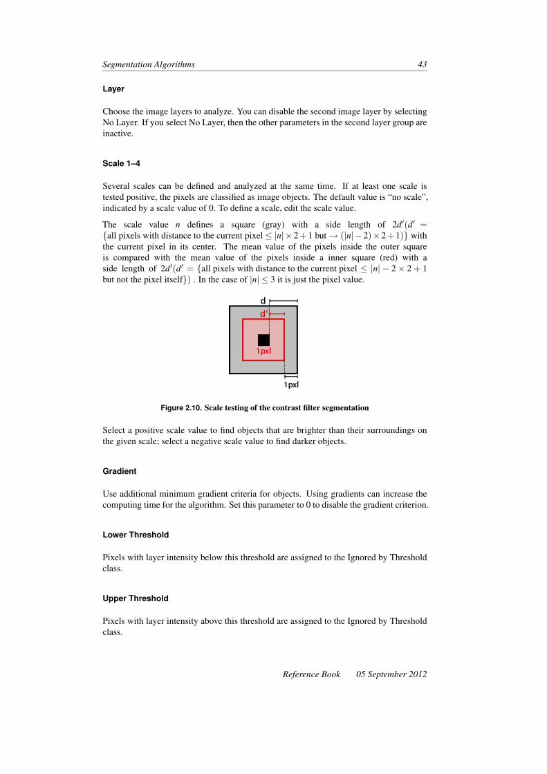
Segmentation Algorithms 43
Layer
Choose the image layers to analyze. You can disable the second image layer by selectingNo Layer. If you select No Layer, then the other parameters in the second layer group areinactive.
Scale 1–4
Several scales can be defined and analyzed at the same time. If at least one scale istested positive, the pixels are classified as image objects. The default value is “no scale”,indicated by a scale value of 0. To define a scale, edit the scale value.
The scale value n defines a square (gray) with a side length of 2d′(d′ ={all pixels with distance to the current pixel≤ |n|×2+1 but→ (|n|−2)×2+1)} withthe current pixel in its center. The mean value of the pixels inside the outer squareis compared with the mean value of the pixels inside a inner square (red) with aside length of 2d′(d′ = {all pixels with distance to the current pixel ≤ |n| − 2× 2 + 1but not the pixel itself}) . In the case of |n| ≤ 3 it is just the pixel value.
Figure 2.10. Scale testing of the contrast filter segmentation
Select a positive scale value to find objects that are brighter than their surroundings onthe given scale; select a negative scale value to find darker objects.
Gradient
Use additional minimum gradient criteria for objects. Using gradients can increase thecomputing time for the algorithm. Set this parameter to 0 to disable the gradient criterion.
Lower Threshold
Pixels with layer intensity below this threshold are assigned to the Ignored by Thresholdclass.
Upper Threshold
Pixels with layer intensity above this threshold are assigned to the Ignored by Thresholdclass.
Reference Book 05 September 2012

44 Developer XD 2.0.4
2.7.4 ShapeCriteria Settings
If you expect coherent and compact image objects, shape criteria parameters provide anintegrated reshaping operation that modifies the shape of image objects by cutting offprotruding parts and filling indentations and hollows.
ShapeCriteria Value
Protruding parts of image objects are declassified if a direct line crossing the hollow issmaller or equal than the ShapeCriteria value. Indentations and hollows of image objectsare classified as the image object if a direct line crossing the hollow is smaller or equalthan the shape criteria value. If you do not want any reshaping, set the value to 0.
Working on Class
Select a class of image objects for reshaping. The pixel classification can be transferredto the image object level using the classification parameters.
2.7.5 Classification Parameters
Enable Class Assignment
Select Yes or No in order to use or disable the classification parameters. If you select No,then the other parameters in the group are inactive.
No Objects
Pixels failing to meet the defined filter criteria are assigned the selected class.
Ignored By Threshold
Pixels with a layer intensity below or above the threshold values are assigned the selectedclass.
Object in First Layer
Pixels that match the filter criteria in first layer, but not the second layer, are assigned theselected class.
Objects in Both Layers
Pixels that match the filter criteria value in both layers are assigned the selected class.
05 September 2012 Reference Book

Segmentation Algorithms 45
Objects in Second Layer
Pixels that match the scale value in second layer, but not the first layer, are assigned theselected class.
2.8 Watershed Segmentation
The Watershed Segmentation algorithm implements a watershed transformation.
The algorithm takes in an image layer, that it regards as topographic map. It then simu-lates a rain drop falling down onto that map and pouring down into a local minima. Allpixels, whose raindrops end up in the same local minima, form an image object (catch-ment basin). Image object borders relate to the watershed lines.
To overcome over-segmentation, the user can apply the ‘seed-based fusion’ principle,where each object can be a ‘seed’ or a ‘candidate’. Objects are merged until there areonly seeds remaining. Seeds will only merge with candidate objects and candidate objectsbecome seeds when defined criteria are met.
2.8.1 Examples
Figure 2.11. Original image and watershed segmentation
Figure 2.12. Original image – Edge image(Sobel) – and watershed segmentation
Reference Book 05 September 2012

46 Developer XD 2.0.4
2.8.2 Supported Domains
Pixel Level; Image Object Level; Current Image Object; Neighbor Image Object; SuperObject; Sub Objects; Linked Objects
2.8.3 Algorithm Parameters
Layer
Select the layer for the algorithm to operate upon.
Invert Level
Specify whether to invert the layer before applying the watershed algorithm.
Connectivity
Select the pixel connectivity; choose from 4-connected or 8-connected.
Seed-Based Fusion
Seed Criterion Select a criterion for seed-based fusion. For no fusion, select <disabled>.The options are:
• Ovfl. Area (pxl): Overflow Area – the number of pixels below the minimumborder pixel
• Ovfl. Height: Overflow Height – minimum border pixel• Ovfl. Depth: Overflow Depth – the difference between the minimum border and
minimum object pixel• Ovfl. Volume: Overflow Volume – the sum of the difference between the minimum
border and the pixel, for all pixels below the minimum border pixel.
Threshold Choose a threshold for the seed criterion.
Seed Criterion Select an additional seed criterion if you wish.
Fuse Super Objects Select whether to fuse super objects.
05 September 2012 Reference Book

3 Basic ClassificationAlgorithms
Classification algorithms analyze image objects according to defined criteria and assignthem to a class that best meets them.
3.1 Assign Class
Assign all objects of the image object domain to the class specified by the Use Classparameter. The membership value for the assigned class is set to 1 for all objects inde-pendent of the class description. The second and third-best classification results are setto 0.
3.1.1 Use Class
Select the class for the assignment from the drop-down list. You can also create a newclass for the assignment.
3.2 Classification
Evaluates the membership value of an image object against a list of selected classes. Theclassification result of the image object is updated according to the class evaluation result.The three best classes are stored in the image object classification result. Classes withouta class description are assumed to have a membership value of 1.
3.2.1 Active Classes
Erase Old Classification, If There Is No New Classification
• If you select Yes and the membership value of the image object is below the accep-tance threshold (see classification settings) for all classes, the current classificationof the image object is deleted
• If you select No and the membership value of the image object is below the accep-tance threshold (see classification settings) for all classes, the current classificationof the image object is kept.
47

48 Developer XD 2.0.4
Use Class Description
• If Yes is selected, class descriptions are evaluated for all classes. The image objectis assigned to the class with the highest membership value.
• If No is selected, class descriptions are ignored. This option delivers valuableresults only if Active Classes contains exactly one class
If you do not use the class description, we recommend you use the Assign Class algorithminstead.
3.3 Hierarchical Classification
The Hierarchical Classification algorithm evaluates the membership value of an imageobject against a list of selected classes.
The classification result of the image object is updated according to the class evaluationresult. The three best classes are stored as the image object classification result. Classeswithout a class description are assumed to have a membership value of 0. Class-relatedfeatures are considered only if explicitly enabled by the according parameter.
This algorithm is optimized for applying complex class hierarchies to entire image objectlevels. This reflects the classification algorithm of eCognition Professional 4. Whenworking with domain-specific classification in processes, the algorithms Assign Classand Classification are recommended.
3.3.1 Active Classes
Choose the list of active classes for the classification.
3.3.2 Use Class-Related Features
Enable to evaluate all class-related features in the class descriptions of the selected classes.If it is disabled these features will be ignored.
3.4 Remove Classification
Delete specific classification results from image objects.
3.4.1 Classes
Select classes that should be deleted from image objects.
3.4.2 Process
Enable to delete computed classification results created via processes and other classifi-cation procedures from the image object.
05 September 2012 Reference Book

Basic Classification Algorithms 49
3.4.3 Manual
Enable to delete manual classification results from the image object.
Reference Book 05 September 2012


4 Advanced ClassificationAlgorithms
Advanced classification algorithms classify image objects that fulfill special criteria, suchas being enclosed by another image object, or being the smallest or largest object in a set.
4.1 Find Domain Extrema
Find Domain Extrema classifies image objects with the smallest or largest feature valueswithin the image object domain, according to an image object feature.
Figure 4.1. Result of Find Domain Extrema, with Extrema Type set to Maximum and FeatureSet to Area
4.1.1 Supported Domains
Image Object Level; Current Image Object; Neighbor Image Object; Super Object; SubObjects; Linked Objects; Image Object List
51

52 Developer XD 2.0.4
4.1.2 Extrema Settings
Extrema Type
Choose Minimum to classify image objects with the smallest feature values and Maxi-mum for image objects with the largest feature values.
Feature
Choose the feature to use for finding the extreme values.
Accept Equal Extrema
This feature enables the algorithm to accept equal extrema. This parameter defines thebehavior of the algorithm if more than one image object is fulfilling the extreme condition.If enabled, all image objects will be classified; if not, none of the image objects will beclassified.
4.02 Compatibility Mode
Select Yes from the Value field to enable compatibility with older software versions (ver-sion 4.02 and older). This parameter will be removed from future versions.
4.1.3 Classification Settings
Specify the classification that will be applied to all image objects fulfilling the extremecondition. At least one class needs to be selected in the active class list for this algorithm.
Active Classes
Choose the list of active classes for the classification.
Erase Old Classification if There is no New Classification
• If you select Yes and the membership value of the image object is below the accep-tance threshold (see classification settings) for all classes, the current classificationof the image object is deleted.
• If you select No and the membership value of the image object is below the accep-tance threshold (see classification settings) for all classes, the current classificationof the image object is kept.
05 September 2012 Reference Book

Advanced Classification Algorithms 53
Use Class Description
• If Yes is selected, class descriptions are evaluated for all classes. The image objectis assigned to the class with the highest membership value.
• If No is selected, class descriptions are ignored. This option delivers valuableresults only if Active Classes contains exactly one class
If you do not use the class description, we recommend you use the Assign Class algorithminstead.
4.2 Find Local Extrema
Find Local Extrema classifies image objects that fulfill a local extrema condition, accord-ing to image object features within a search domain in their neighborhoods.
Image objects with either the smallest or the largest feature value within a specific neigh-borhood will be classified according to the classification settings.
4.2.1 Supported Domains
Image Object Level; Current Image Object; Neighbor Image Object; Super Object; SubObjects; Linked Objects; Image Object List
4.2.2 Search Settings
The search settings let you specify a search domain for the neighborhood around theimage object.
Class Filter
Choose the classes to be searched. Image objects will be part of the search domain ifthey are classified with one of the classes selected in the class filter. Always add the classselected for the classification to the search class filter. Otherwise cascades of incorrectextrema resulting from the reclassification during the execution of the algorithm mayappear.
Search Range
Define the search range in pixels. All image objects with a distance below the givensearch range will be part of the search domain. Use the drop-down arrows to select zeroor positive numbers.
Connected
Enable to ensure that all image objects in the search domain are connected with the ana-lyzed image object via other objects in the search range.
Reference Book 05 September 2012

54 Developer XD 2.0.4
3.5 Compatibility Mode
Select Yes from the Value field to enable compatibility with older software versions (ver-sion 3.5 and older). This parameter will be removed in future versions.
4.2.3 Conditions
Define the extrema conditions.
Extrema Type
Choose Minimum for classifying image objects with the smallest feature values and Max-imum for classifying image objects with largest feature values.
Feature
Choose the feature to use for finding the extreme values
Equal Extrema Condition
This parameter defines the behavior of the algorithm if more than one image object isfulfilling the extrema condition:
• Do Not Accept Equal Extrema means no image objects will be classified• Accept Equal Extrema means all image objects will be classified• Accept First Equal Extrema will result in the classification of the first of the image
objects.
4.2.4 Classification Settings
Specify the classification that will be applied to all image objects fulfilling the extremecondition. At least one class needs to be selected in the active class list for this algorithm.
Active Classes
Choose the list of active classes for the classification.
Erase Old Classification if There is no New Classification
• If you select Yes and the membership value of the image object is below the accep-tance threshold (see classification settings) for all classes, the current classificationof the image object is deleted.
• If you select No and the membership value of the image object is below the accep-tance threshold (see classification settings) for all classes, the current classificationof the image object is kept.
05 September 2012 Reference Book

Advanced Classification Algorithms 55
Use Class Description
• If Yes is selected, class descriptions are evaluated for all classes. The image objectis assigned to the class with the highest membership value.
• If No is selected, class descriptions are ignored. This option delivers valuableresults only if Active Classes contains exactly one class
If you do not use the class description, we recommend you use the Assign Class algorithminstead.
4.3 Find Enclosed by Class
Find and classify image objects that are completely enclosed by image objects belongingto certain classes.
If an image object is located at the border of the image, it will not be found and classifiedby Find Enclosed by Class. The shared part of the outline with the image border will notbe recognized as the enclosing border.
Figure 4.2. Left: Input of Find Enclosed by Class: Image Object Domain: Image ObjectLevel, Class Filter: N0, N1. Enclosing class: N2. Right: Result of Find Enclosed by Class:Enclosed objects get classified with the class ‘enclosed’. Note that the objects at the upperimage border are not classified as enclosed
4.3.1 Supported Domains
Image Object Level; Current Image Object; Neighbor Image Object; Super Object; SubObjects; Linked Objects; Image Object List
4.3.2 Search Settings
Enclosing Classes
Choose the classes that might be enclosing the image objects
Reference Book 05 September 2012

56 Developer XD 2.0.4
Compatibility Mode
Select Yes from the Value field to enable compatibility with older software versions (ver-sion 3.5 and 4.0). This parameter will be removed with future versions.
4.3.3 Classification Settings
Choose the classes that should be used to classify enclosed image objects.
Active Classes
Choose the list of active classes for the classification.
Erase Old Classification If There Is No New Classification
• If you select Yes and the membership value of the image object is below the accep-tance threshold (see classification settings) for all classes, the current classificationof the image object is deleted.
• If you select No and the membership value of the image object is below the accep-tance threshold (see classification settings) for all classes, the current classificationof the image object is kept.
Use Class Description
• If Yes is selected, class descriptions are evaluated for all classes. The image objectis assigned to the class with the highest membership value.
• If No is selected, class descriptions are ignored. This option delivers valuableresults only if Active Classes contains exactly one class
If you do not use the class description, we recommend you use the Assign Class algorithminstead.
4.4 Find Enclosed by Image Object
Find and classify image objects that are completely enclosed by image objects from theimage object domain. Enclosed image objects located at the image border will be foundand classified by the Find Enclosed by Image Object algorithm. The shared part of theoutline with the image border will be recognized as the enclosing border.
In figure 4.3 on the facing page, the inputs for the left-hand image in Find Enclosedby Image Object are image object domain: image object level, class filter: N2. On theright-hand image, using the same algorithm, enclosed objects are classified with the classenclosed. Note that the objects at the upper image border are classified as enclosed.
4.4.1 Classification Settings
Choose the class that will be used to classify enclosed image objects.
05 September 2012 Reference Book

Advanced Classification Algorithms 57
Figure 4.3. Comparison of Find Enclosed by Class
Active Classes
Choose the list of active classes for the classification.
Erase Old Classification If There Is No New Classification
• If you select Yes and the membership value of the image object is below the accep-tance threshold (see classification settings) for all classes, the current classificationof the image object is deleted.
• If you select No and the membership value of the image object is below the accep-tance threshold (see classification settings) for all classes, the current classificationof the image object is kept.
Use Class Description
• If Yes is selected, class descriptions are evaluated for all classes. The image objectis assigned to the class with the highest membership value.
• If No is selected, class descriptions are ignored. This option delivers valuableresults only if Active Classes contains exactly one class
If you do not use the class description, we recommend you use the Assign Class algorithminstead.
4.5 Connector
Classify the image objects that make up the shortest connection between the current im-age object and another image object that meets the conditions described by the connectionsettings.
The process starts to search from the current image object along objects that meet theconditions as specified by Connect Via and Super Object Mode Via, until it reaches an
Reference Book 05 September 2012

58 Developer XD 2.0.4
image object that meets the conditions specified by Connect To and Super Object ModeTo. All image objects that are part of the resulting connection are assigned to the selectedclass.
You can define the maximum search range under Search Range In Pixels.
4.5.1 Connector Settings
Connector Via
Choose the classes whose image objects you want to be searched when determining theconnection. Image objects assigned to other classes will not be taken into account.
Super Object Mode Via
Limit the number of image objects that are taken into account for the connection byspecifying a superordinate object. Choose one of the following options:
• Don’t Care: Use any image object• Different Super Object: Use only images with a different superobject than the seed
object• Same Super Object: Use only image objects with the same superobject as the seed
object
Connect To
Choose the classes whose image objects you want to be searched when determining adestination for the connection. Image objects assigned to other classes will not be takeninto account.
Super Object Mode To
Limit the number of image objects that are taken into account for the destination of theconnection by specifying a superordinate object. Choose one of the following options:
• Don’t Care use any image object• Different Super Object use only images with a different superobject than the seed
object• Same Super Object use only image objects with the same superobject as the seed
object.
Search Range
Enter the Search Range in pixels that you wish to search.
05 September 2012 Reference Book

Advanced Classification Algorithms 59
4.5.2 Classification Settings
Choose the class that should be used to classify the connecting objects.
Erase Old Classification If There Is No New Classification
• If you select Yes and the membership value of the image object is below the accep-tance threshold (see classification settings) for all classes, the current classificationof the image object is deleted.
• If you select No and the membership value of the image object is below the accep-tance threshold (see classification settings) for all classes, the current classificationof the image object is kept.
Use Class Description
• If Yes is selected, class descriptions are evaluated for all classes. The image objectis assigned to the class with the highest membership value.
• If No is selected, class descriptions are ignored. This option delivers valuableresults only if Active Classes contains exactly one class
If you do not use the class description, we recommend you use the Assign Class algorithminstead.
4.6 Assign Class By Slice Overlap (Prototype)
4.6.1 Supported Domains
Execute; Image Object Level; Current Image Object; Neighbor Image Object; SuperObject; Sub Objects; Linked Objects; Image Object List
4.6.2 Algorithm Parameters
Use Class
Select class for assignment
Candidate Domain
Class filter for objects that are considered.
Create 3D Objects
Create 3D objects
Reference Book 05 September 2012

60 Developer XD 2.0.4
Slices Up
Describes how many slices the object is copied up. Use −1 for no limit.
Slices Down
Describes how many slices the object is copied down. Use −1 for no limit.
4.7 Optimal Box (Prototype)
Generate member functions for classes by looking for the best separating features basedupon sample training.
4.7.1 Supported Domains
Execute; Image Object Level; Current Image Object; Neighbor Image Object; SuperObject; Sub Objects; Linked Objects; Image Object List
4.7.2 Sample Class Parameters
For Target Samples
Select a class or create a new class that provides samples for the target class (the class tobe ‘trained’).
For Rest Samples
Select a class or create a new class that provides samples for the rest of the domain.
4.7.3 Insert Membership Function Parameters
For Target Samples Into
Select a class or create a new class that receives membership functions after optimizationfor target. If set to unclassified, the target sample class is used.
For Rest Samples Into
Select a class or create a new class that receives inverted similarity membership functionsafter optimization for target. If set to unclassified, the rest sample class is used.
05 September 2012 Reference Book
Advanced Classification Algorithms 61
Clear All Membership Functions
When inserting new membership functions into the active class, choose whether to clearall existing membership functions or clear only those from input feature space:
• No, Only Clear if Associated with Input Feature Space: Clear membership func-tions only from the input feature space when inserting new membership functionsinto the active class.
• Yes, always clear all membership functions: Clear all membership functions wheninserting new membership functions into the active class.
4.7.4 Feature Optimization Parameters
Input Feature Set
Input set of descriptors from which a subset will be chosen. Click the ellipsis buttonto open the Select Multiple Features dialog box. The Ensure Selected Features are inStandard Nearest Neighbor Feature Space checkbox is selected by default.
Minimum Number of Features
The minimum number of features descriptors to employ in a class. The default is 1.
Maximum Number of Features
The minimum number of features descriptors to employ in a class.
4.7.5 Optimization Settings Parameters
Weighted Distance Exponent
Enter a number greater than 0 to decrease weighting with increasing distance. Enter 0 toweight all distances equally. The default is 2.
Simplification Factor Mode
The simplification factor is calculated as:
ecur dimension
total dim
The following values are available:
• Do Not Apply: Simplification factor is not applied• Apply to Weighted Distance: Weighted distance is multiplied by simplification
factor trades off simplicity against distance separation for equally good overlap• Apply to Overlap: Overlap is divided by simplification factor trades off simplicity
against false positives.
Reference Book 05 September 2012

62 Developer XD 2.0.4
Simplification Factor Exponent
The exponent where the simplification factor is calculated as:
ecur dimension
total dim
4.7.6 Optimization Output Parameters
False Positives Variable
Set this variable to the number of false positives after execution.
False Negatives Variable
Set this variable to the number of false negatives after execution.
False Positives Object List
Select an existing image object list variable, to which image objects associated with falsepositive samples are added. If a value is not set, no output occurs. Please note thatsamples stored in the workspace have no associated objects, so cannot be included in thelist.
False Negatives Object List
Select an existing image object list variable, to which image objects associated with falsenegative samples are added. If a value is not set, no output occurs. Please note thatsamples stored in the workspace have no associated objects, so cannot be included in thelist.
Separated Positives Object List (For Selected Feature Space)
This list contains image objects associated with positive samples, which are separatedfrom other positive samples by false positives, using the generated feature space.
Separated Positives Object List (From ‘For Target Samples Into’ Class)
This list contains image objects associated with positive samples, which are separatedfrom other positive samples by false positives, using a feature space from ‘For TargetSamples Into’.
Show Info in Message Console
Show information on feature evaluations in message console.
05 September 2012 Reference Book
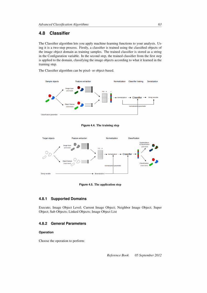
Advanced Classification Algorithms 63
4.8 Classifier
The Classifier algorithm lets you apply machine-learning functions to your analysis. Us-ing it is a two-step process. Firstly, a classifier is trained using the classified objects ofthe image object domain as training samples. The trained classifier is stored as a stringin the Configuration variable. In the second step, the trained classifier from the first stepis applied to the domain, classifying the image objects according to what it learned in thetraining step.
The Classifier algorithm can be pixel- or object-based.
Figure 4.4. The training step
Figure 4.5. The application step
4.8.1 Supported Domains
Execute; Image Object Level; Current Image Object; Neighbor Image Object; SuperObject; Sub Objects; Linked Objects; Image Object List
4.8.2 General Parameters
Operation
Choose the operation to perform:
Reference Book 05 September 2012

64 Developer XD 2.0.4
• Train: Train a classifier. The domain objects serve as training samples.• Apply: Apply a trained classifier to the domain objects.• Query: Query attributes of a trained classifier.
4.8.3 Train: General Parameters
Configuration
Enter or select the variable to store the configuration to
Use Samples Only
Choose Yes or No depending on whether you want to use sample image objects only
4.8.4 Train: Feature Parameters
Type
Choose from:
• Object-Based: Use image objects• Pixel-Based: Use the pixels contained in image objects
Feature
Select features used for object based classification.
Layer array
Select layer array used for pixel based classification.
4.8.5 Train: Classifier Parameters
Select a classifier to train from Decision Tree, Bayes, KNN or SVM. For more informa-tion about the supported classifiers, see the OpenCV C++ Reference.1
4.8.6 Apply: General Parameters
Configuration
Select the variable to load the configuration from.
1. opencv.willowgarage.com/documentation/cpp/index.html
05 September 2012 Reference Book

Advanced Classification Algorithms 65
4.8.7 Apply: Feature Parameters
Choose the same settings as in the training step.
Type
Choose from:
• Object-Based: Use image objects• Pixel-Based: Use the pixels contained in image objects
Layer Array
Select a layer array to use as pixel-based features.
4.8.8 Query: General Parameters
Configuration
Select the variable to load the configuration from.
4.8.9 Query: Query Information about a trained classifier
Type
Select from:
• Bayes• KNN• SVM• Decision Tree. Selecting Decision Tree displays the following options:
– Operation. Select from:* Query Parameter:
· Depth:· Min Sample Count:· Depth:
* Query Node:· ld: Specify the tree node to query properties from· ld leaf: Specify the variable to receive a property· Assigned Class: Specify the class variable to receive· Left Child Node: Specify the variable to receive a property· Right Child Node: Specify the variable to receive a property· Split Feature Index: Specify the variable to receive a property· Split Threshold: Specify the variable to receive a property
* Plot: Export a diagram of the decision tree as a Windows bitmap· Image Path: Enter the image path to export the image file
Reference Book 05 September 2012

66 Developer XD 2.0.4
* Convert to CNL: Generate CNL code, that is equivalent to the decisiontree
· Target Process Path: Location of the CNL tree· Prefix: Add a prefix.
For more information about classifier functions, see the OpenCV C++ Reference.2
2. opencv.willowgarage.com/documentation/cpp/index.html
05 September 2012 Reference Book

5 Variables OperationAlgorithms
Variable operation algorithms are used to modify the values of variables. They providedifferent methods for performing computations based on existing variables and imageobject features, and for storing the results within variables.
5.1 Timer
The Timer algorithm adds to a variable the elapsed time of its sub-processes (with the ex-ception of customized algorithms). It is useful for debugging and improving performancein rule sets.
5.1.1 Supported Domains
Execute
5.1.2 Algorithm Parameters
Timer Variable
Select the variable to which the process execution time and all its subprocesses will beadded.
5.2 Update Variable
Perform an arithmetic operation on a variable.
5.2.1 Supported Domains
Execute; Image Object Level; Current Image Object; Neighbor Image Object; SuperObject; Sub Objects; Linked Objects; Image Object List; Array
67

68 Developer XD 2.0.4
5.2.2 Algorithm Parameters
Variable Type
Object, scene, feature, class, level, image layer, thematic layer, or map variables must beselected as the vriable type. Select the variable assignment, according to the variable typeselected in the Variable Type field. To select a variable assignment, click in the field anddo one of the following depending on the variable type:
• For object variables, use the drop-down arrow to open the Select Single Featuredialog box and select a feature or create a new feature variable
• For scene variables, use the drop down arrow to open the Select Single Featuredialog box and select a feature or create a new feature variable
• For feature variables, use the ellipsis button to open the Select Single Feature dialogbox and select a feature or create a new feature variable
• For class variables, use the drop-down arrow to select from existing classes orcreate a new class
• For level variables, use the drop-arrow to select from existing levels• For image layer variables, select the image layer you want to use for the update
operation• For thematic layer variables, select the thematic layer you want to use for the update
operation• For map variables, select the map name you want to use for the update operation• For array variables, select the array you want to use for the update operation.
Variable
Select an existing variable or enter a name to create a new one. If you have not alreadycreated a variable, the Create Variable dialog box will open. Only scene variables can beused in this field.
Operation
This field displays only for object and scene variables. Select one of the arithmetic oper-ations:
Value Description
= Assign a value.
+= Increase by value.
-= Decrease by value.
x= Multiply by value.
/= Divide by value.
05 September 2012 Reference Book

Variables Operation Algorithms 69
Assignment
If Scene Variable or Object Variable is selected, you can assign either a value or a feature.This setting enables or disables the remaining parameters. If Image Layer Variable orThematic Layer Variable is selected, you can assign either a layer or index.
Value
This field displays only for Scene and Object variables. If you have selected to assign byvalue, you may enter a value or a variable. To enter text use quotes. The numeric valueof the field or the selected variable will be used for the update operation.
Feature
This field displays only for scene and object variables. If you have chosen to assign byfeature you can select a single feature. The feature value of the current image object willbe used for the update operation.
Comparison Unit
This field displays only for Scene and Object variables. If you have chosen to assignby feature, and the selected feature has units, then you may select the unit used by theprocess. If the feature has co-ordinates, select Co-ordinates to provide the position ofthe object within the original image or select Pixels to provide the position of the objectwithin the currently used scene.
Arithmetic Expression
For all variables, you may assign an arithmetic expression to calculate a value.
Array Item
The Array Item parameter appears when ‘by array item’ is selected in the Assignmentparameter. You may create a new array item or assign an Image Object Domain.
5.3 Compute Statistical Value
Perform a statistical operation on the feature distribution within an image object domainand store the result in a scene variable.
5.3.1 Supported Domains
Image Object Level; Current Image Object; Neighbor Image Object; Super Object; SubObjects; Linked Objects; Image Object List
Reference Book 05 September 2012

70 Developer XD 2.0.4
5.3.2 Active Classes
Choose the list of active classes for the classification.
5.3.3 Algorithm Parameters
Variable
Select an existing variable or enter a name to create a new one. If you have not alreadycreated a variable, the Create Variable dialog box will open. Only scene variables can beused in this field.
Operation
Select one of the statistical operations listed in table 5.0 on the current page, AvailableOperations for Compute Statistical Value Algorithm.
Table 5.0. Available Operations for Compute Statistical Value Algorithm
Value Description
Number Count the objects of the currently selected image object domain
Sum Return the sum of the feature values from all objects of the selected imageobject domain
Maximum Return the maximum feature value from all objects of the selected imageobject domain
Minimum Return the minimum feature value from all objects of the selected imageobject domain
Mean Return the mean feature value of all objects from the selected imageobject domain
StandardDeviation
Return the standard deviation of the feature value from all objects of theselected image object domain
Median Return the median feature value from all objects of the selected imageobject domain
Quantile Return the feature value, where a specified percentage of objects from theselected image object domain have a smaller feature value
Parameter
If you have selected the quantile operation, specify the percentage threshold.
05 September 2012 Reference Book

Variables Operation Algorithms 71
Feature
Select the feature that is used to perform the statistical operation. (This parameter is notused if you select Number as your operation.)
Unit
• You may select a unit for the operation• For positional features (such as X Max) you can choose Pixels from the drop-down
list to return the relative object position (such as the position within a tile or subset).• If you select a positional feature you can select Co-ordinates in the drop-down list
to use the absolute co-ordinates if desired.
5.4 Compose Text
Assign a string variable text parts. Content of variable will be replaced by the text as-signed with parameters text prefix and text suffix.
5.4.1 Supported Domains
Execute; Image Object Level; Current Image Object; Neighbor Image Object; SuperObject; Sub Objects; Linked Objects; Image Object List
5.4.2 Algorithm Parameters
Result
Enter the name of the variable that will store the composed text.
Text Prefix
Edit the beginning of the composed text: the text suffix is attached afterwards. You canenter one of the following:
• Text (between quotation marks)• A number value (without quotation marks)• A variable (without quotation marks)
Text Suffix
Edit the end of the composed text: it is attached after the text prefix. You can enter oneof the following:
• Text (between quotation marks)• A number value (without quotation marks)• A variable (without quotation marks)
Reference Book 05 September 2012

72 Developer XD 2.0.4
Examples Some possible combinations are shown below:
Text prefix Type Text suffix Type Composed Text
“class” Text 1 Number value class1
CLASSNAMEID Variable ID Variable class1
5.5 Update Region
Modify a region variable. You can resize or move the region defined by a region variable,or enter its co-ordinates. Alternatively, you can use the co-ordinates of an image objectbounding box or the active pixel for a region update.
5.5.1 Supported Domains
Execute; Image Object Level; Current Image Object; Neighbor Image Object; SuperObject; Sub Objects; Linked Objects; Array
5.5.2 Algorithm Parameters
Variable
Select an existing region variable or create a new one. To create a new variable, type aname for the new variable and click OK to open the Create Region Variable dialog boxfor further settings.
Mode
Select the operation for modifying the region defined by the region variable (see table 5.1,Update Region Algorithm Modes).
5.6 Update Image Object List
The Update Image Object List algorithm allows you to modify list variables, add objects,remove objects, and clear and compact lists.
5.6.1 Supported Domains
Execute; Image Object Level; Current Image Object; Neighbor Image Object; Superob-ject; Sub-objects; Linked Objects
05 September 2012 Reference Book
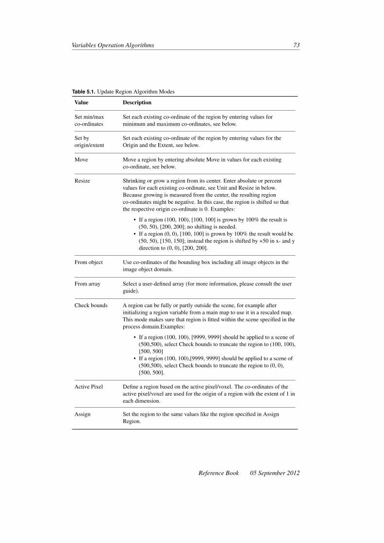
Variables Operation Algorithms 73
Table 5.1. Update Region Algorithm Modes
Value Description
Set min/maxco-ordinates
Set each existing co-ordinate of the region by entering values forminimum and maximum co-ordinates, see below.
Set byorigin/extent
Set each existing co-ordinate of the region by entering values for theOrigin and the Extent, see below.
Move Move a region by entering absolute Move in values for each existingco-ordinate, see below.
Resize Shrinking or grow a region from its center. Enter absolute or percentvalues for each existing co-ordinate, see Unit and Resize in below.Because growing is measured from the center, the resulting regionco-ordinates might be negative. In this case, the region is shifted so thatthe respective origin co-ordinate is 0. Examples:
• If a region (100, 100), [100, 100] is grown by 100% the result is(50, 50), [200, 200]; no shifting is needed.
• If a region (0, 0), [100, 100] is grown by 100% the result would be(50, 50), [150, 150]; instead the region is shifted by +50 in x- and ydirection to (0, 0), [200, 200].
From object Use co-ordinates of the bounding box including all image objects in theimage object domain.
From array Select a user-defined array (for more information, please consult the userguide).
Check bounds A region can be fully or partly outside the scene, for example afterinitializing a region variable from a main map to use it in a rescaled map.This mode makes sure that region is fitted within the scene specified in theprocess domain.Examples:
• If a region (100, 100), [9999, 9999] should be applied to a scene of(500,500), select Check bounds to truncate the region to (100, 100),[500, 500]
• If a region (100, 100),[9999, 9999] should be applied to a scene of(500,500), select Check bounds to truncate the region to (0, 0),[500, 500].
Active Pixel Define a region based on the active pixel/voxel. The co-ordinates of theactive pixel/voxel are used for the origin of a region with the extent of 1 ineach dimension.
Assign Set the region to the same values like the region specified in AssignRegion.
Reference Book 05 September 2012

74 Developer XD 2.0.4
5.6.2 Algorithm Parameters
Variable
Select an existing image object list variable or create a new one. The computed value willbe stored in the image object list variable.
Mode
Select the operation to use to modify the object list.
• Add Image Objects adds all objects in the current image object domain to the se-lected image object list. All image object domains are supported
• Remove Image Objects removes all image objects in the current image object do-main from the list. All image object domains are supported
• Clear List removes all image objects from the selected image object list. The Exe-cute image object domain is supported.
• Compact List removes all invalid objects from the list. The Execute image objectdomain is supported.
Feature
Select which feature you wish to use for sorting.
Sorting Order
Select the sorting order for the image objects.
5.7 Update Feature List
Update Feature List lets you to create a list that contains features, which can be laterexported (for example as project statistics). The feature list can contain any combinationof features, all of which can be added and removed from a list. Features can also be addedand removed between lists and entire lists can be deleted.
5.7.1 Supported Domains
Execute
5.8 Automatic Threshold
Calculates a threshold value to be used for multi-threshold segmentation.
05 September 2012 Reference Book
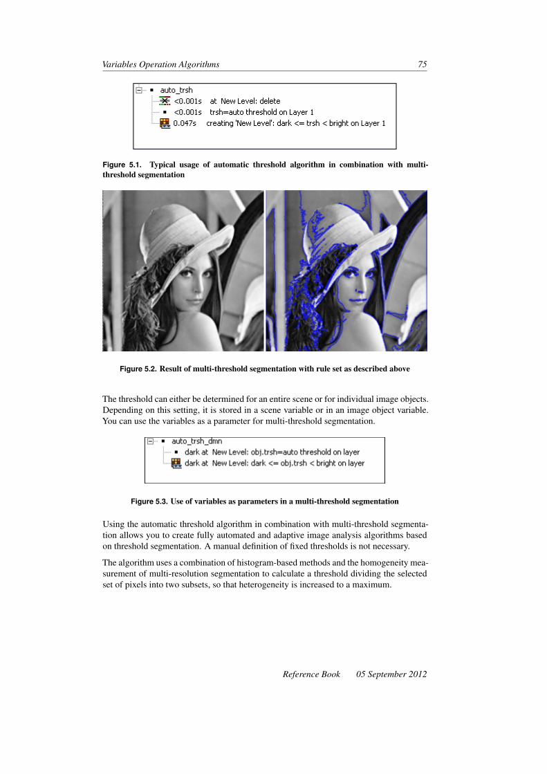
Variables Operation Algorithms 75
Figure 5.1. Typical usage of automatic threshold algorithm in combination with multi-threshold segmentation
Figure 5.2. Result of multi-threshold segmentation with rule set as described above
The threshold can either be determined for an entire scene or for individual image objects.Depending on this setting, it is stored in a scene variable or in an image object variable.You can use the variables as a parameter for multi-threshold segmentation.
Figure 5.3. Use of variables as parameters in a multi-threshold segmentation
Using the automatic threshold algorithm in combination with multi-threshold segmenta-tion allows you to create fully automated and adaptive image analysis algorithms basedon threshold segmentation. A manual definition of fixed thresholds is not necessary.
The algorithm uses a combination of histogram-based methods and the homogeneity mea-surement of multi-resolution segmentation to calculate a threshold dividing the selectedset of pixels into two subsets, so that heterogeneity is increased to a maximum.
Reference Book 05 September 2012

76 Developer XD 2.0.4
Figure 5.4. Result of automatic threshold calculation for fluorescent microscope image
5.8.1 Supported Domains
Pixel Level; Image Object Level; Current Image Object; Neighbor Image Object; SuperObject; Sub Objects; Linked Objects; Image Object List
5.8.2 Algorithm Parameters
Image Layer
Select the image layer you want to be used for automatic threshold determination.
Value Range
Define the value range that is taken into account for automatic threshold determination.
• Entire Value Range the complete threshold value range is taken into account.• Restricted Value Range the threshold values within the specified interval (Min.
Value Max.Value) are taken into account.
Min. Value
If the value range parameter is set to Restricted Value Range, define a minimum value forthe automatically determined threshold.
05 September 2012 Reference Book

Variables Operation Algorithms 77
Max. Value
If the value range parameter is set to Restricted Value Range, define a maximum valuefor the automatically determined threshold.
Threshold
Select the variable where the threshold value is to be saved. You can either select a nu-meric scene variable or a numeric image object variable (type Double). Saving thresholdvalues in scene variables is most useful in combination with the Pixel Level domain. Sav-ing threshold values in image object variables allows you to differentiate between theimage objects of different image object domains.
Quality
Select the variable in which a quality control parameter for the threshold value is to bestored. The quality control parameter reflects the internal criterion according to whichthe threshold is determined. The higher its value, the more distinct the segmentation intoimage objects. You can use the quality control parameter to implement fully automatedsegmentation processes splitting up the image object domain into image objects that meetthe predefined requirements.
5.9 Update Array
The Update Array algorithm is used to update user-defined arrays in rule sets. For moreinformation on creating arrays, please consult the Definiens Developer XD 2.0.4 userguide.
5.9.1 Supported Domains
Execute; Image Object Level; Current Image Object; Neighbor Image Object; SuperObject; Sub Objects; Linked Objects
5.9.2 Algorithm Parameters
Array
Select an array from the drop-down list.
The array may be number, string, class, image layer, thematic layer, level, feature, regionor map name.
Reference Book 05 September 2012

78 Developer XD 2.0.4
Mode
The following options are available to modify the array:
1. Add Values: Select a value to add to the array2. Add Based From Array Items: Add a value from a specified array3. Add Based From Feature: Add a value to an array derived from a feature4. Update Value: Enter an index or value pair for the value to be updated5. Remove By Value: Select a value to remove from the array6. Remove By Index: Select the index of the value to be removed7. Clear: Remove all values from the array8. Sort: Sort array values in ascending or descending order.
Selecting options 1–3 will display the Add Value parameter. Select ‘only once’ for asingle value; selecting ‘always’ allows duplicates.
05 September 2012 Reference Book

6 Basic Object ReshapingAlgorithms
Basic reshaping algorithms modify the shape of existing image objects. They executeoperations such as merging image objects and splitting them into their sub-objects.
6.1 Remove Objects
Merge image objects in the image object domain. Each image object is merged intothe neighbor image object with the largest common border. This algorithm is especiallyhelpful for clutter removal.
6.1.1 Supported Domains
Image Object Level; Current Image Object; Neighbor Image Object; Super Object; SubObjects; Linked Objects; Image Object List
6.1.2 Algorithm Parameters
Target Class
Click the ellipsis button to open the Edit Classification Filter dialog box and select thetarget classes to which the image objects in the image object domain will be merged.
Show Advanced Paramaters
Changing this value to Yes activates the following options:
Merge By Merge By allows you merge image objects based on shape or color. Mergingby shape merges image objects to their neighbors, based on the longest common border.Merging by color merges neighbors based on the smallest layer value difference.
Merging by shape activates the following parameters:
• If Use Threshold has a value of Yes, the Border Threshold parameter is activated
79

80 Developer XD 2.0.4
– Enter a value in Border Threshold – only image objects with a common borderlength longer than or equal to this threshold will be merged
– If Use Legacy Mode is set to Yes, the algorithm will not look for a commonsuperobject. (If a superobject level exists, objects may not be completelyremoved.)
Merging by color activates the following parameters:
• If Use Threshold has a value of Yes, the Color Threshold parameter is activated.– In Layer Usage, select the layers to be analyzed– Enter a value in Color Threshold – only image objects with a color difference
smaller than or equal to neigboring image objects will be merged– If Use Legacy Mode is set to Yes, the algorithm will not look for a common
superobject. (If a superobject level exists, objects may not be completelyremoved.)
6.2 Merge Region
Merge all image objects in the image object domain.
Figure 6.1. Result of merge region algorithm on all image objects classified as parts
6.2.1 Supported Domains
Image Object Level; Current Image Object; Neighbor Image Object; Super Object; SubObjects; Linked Objects; Image Object List
6.2.2 Algorithm Parameters
Fusion Super Objects
Enable the fusion of affiliated super objects.
05 September 2012 Reference Book

Basic Object Reshaping Algorithms 81
Use Thematic Layers
Enable to keep borders defined by thematic layers that were active during the initial seg-mentation of this image object level.
6.3 Grow Region
Enlarge image objects defined in the image object domain by merging them with neigh-boring image objects (“candidates”) that match the criteria specified in the parameters.
The grow region algorithm works in sweeps. That means each execution of the algorithmmerges all direct neighboring image objects according to the parameters. To grow imageobjects into a larger space, you may use the Loop While Something Changes checkboxor specify a specific number of cycles.
Figure 6.2. Result of looped grow region algorithm on image objects of class seed and candi-date class N1. Note that the two seed objects in the image center grow to fill the entire spaceoriginally covered by objects of class N1 while still being two separate objects
6.3.1 Supported Domains
Image Object Level; Current Image Object; Neighbor Image Object; Super Object; SubObjects; Linked Objects; Image Object List
6.3.2 Algorithm Parameters
Candidate Classes
Choose the classes of image objects that can be candidates for growing the image object.
Reference Book 05 September 2012
82 Developer XD 2.0.4
Fusion Super Objects
Enable the fusion of affiliated super objects.
Candidate Condition
Choose an optional feature to define a condition that neighboring image objects need tofulfill in addition to be merged into the current image object.
Use Thematic Layers
Enable to keep borders defined by thematic layers that were active during the initial seg-mentation of this image object level.
6.4 Convert to Sub-objects
Split all image objects of the image object domain into their sub-objects.
6.4.1 Supported Domains
Image Object Level; Current Image Object; Neighbor Image Object; Super Object; SubObjects; Linked Objects; Image Object List
6.4.2 Algorithm Parameters
None
6.5 Convert Image Objects
Convert image objects to a specified type, based on the differences among image objecttypes with regard to their spatial connectivity and dimensions.
6.5.1 Supported Domains
Image Object Level; Current Image Object; Neighbor Image Object; Super Object; SubObjects; Linked Objects
05 September 2012 Reference Book
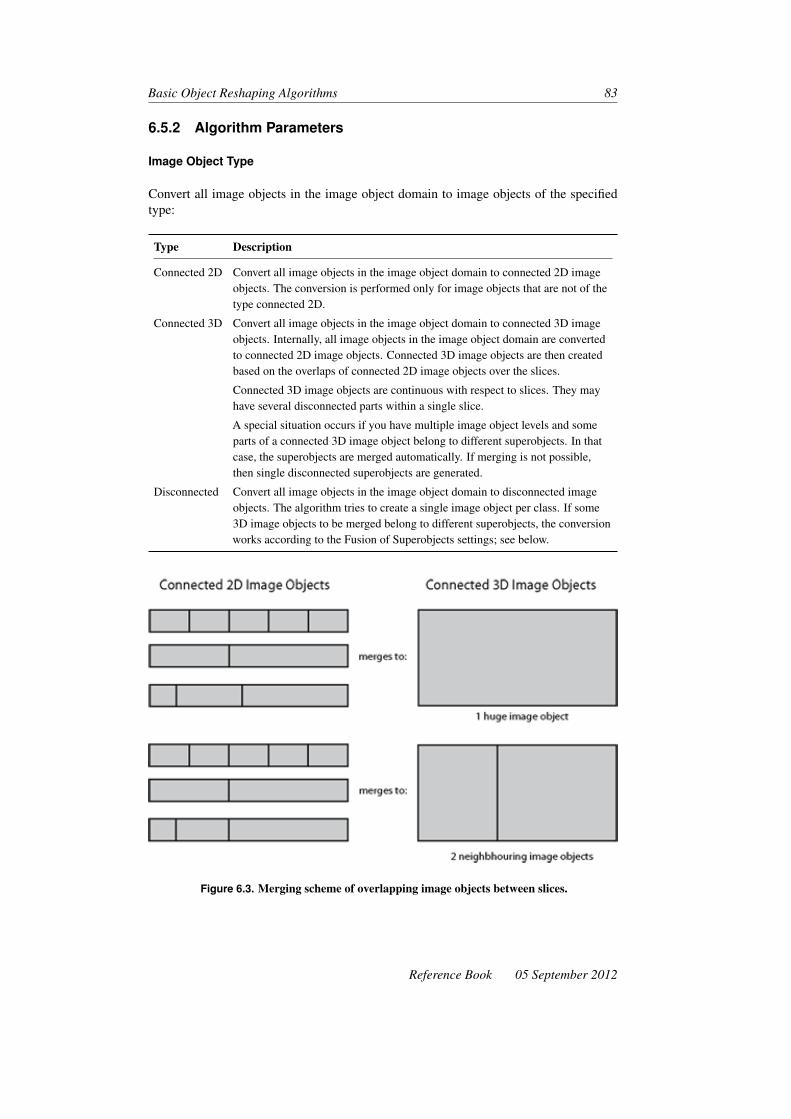
Basic Object Reshaping Algorithms 83
6.5.2 Algorithm Parameters
Image Object Type
Convert all image objects in the image object domain to image objects of the specifiedtype:
Type Description
Connected 2D Convert all image objects in the image object domain to connected 2D imageobjects. The conversion is performed only for image objects that are not of thetype connected 2D.
Connected 3D Convert all image objects in the image object domain to connected 3D imageobjects. Internally, all image objects in the image object domain are convertedto connected 2D image objects. Connected 3D image objects are then createdbased on the overlaps of connected 2D image objects over the slices.
Connected 3D image objects are continuous with respect to slices. They mayhave several disconnected parts within a single slice.
A special situation occurs if you have multiple image object levels and someparts of a connected 3D image object belong to different superobjects. In thatcase, the superobjects are merged automatically. If merging is not possible,then single disconnected superobjects are generated.
Disconnected Convert all image objects in the image object domain to disconnected imageobjects. The algorithm tries to create a single image object per class. If some3D image objects to be merged belong to different superobjects, the conversionworks according to the Fusion of Superobjects settings; see below.
Figure 6.3. Merging scheme of overlapping image objects between slices.
Reference Book 05 September 2012

84 Developer XD 2.0.4
Fusion of Super Objects
This parameter enables you to specify the effect on super objects. If this parameter is setto Yes, super objects will also be fused. This will usually have the effect that affectedsuper objects will be converted to disconnected objects. If this parameter is set to No, thesuper objects stay untouched. In this case, fusion of the active image objects is restrictedby the extent of the super objects.
• If the value is yes, superobjects are merged. If superobjects cannot be merged intoa single connected image object they are merged into single disconnected imageobjects (default)
• If the value is no, superobjects are not merged and only image objects having thesame superobject are merged. Consequently, there can be several disconnectedimage objects per class.
6.6 Cut Objects at Region
Cut all image objects within the image object domain that overlap the border of a givenregion. Each image object to be cut is split into two image objects, called pieces: one iscompletely within the region and one is completely outside.
6.6.1 Supported Domains
Image Object Level; Current Image Object; Neighbor Image Object; Super Object; SubObjects; Linked Objects
6.6.2 Algorithm Parameters
Region
Select or enter the name of an existing region. Alternatively, you can enter the co-ordinates of a region specified by its origin (xG,yG) , which is the lower left corner, andits size [Rx,Ry,Rz,Rt ]. The input pattern is: (xG,yG,zG, tG), [Rx,Ry,Rz,Rt ]. Alternatively,you can select a variable. To create a new variable, type a name for the new variable andclick OK or press Enter to open the Create Variable dialog box for further settings.
Object Type Inner Pieces
Define the type of all image objects (pieces) located inside the region, no matter if theyare cut or not:
05 September 2012 Reference Book
Basic Object Reshaping Algorithms 85
Value Description
Keep current Keep current type (default)
Connected 2D Convert resulting image objects to connected 2D image objects.
Connected 3D Convert resulting image objects to connected 3D image objects (only availablewith Definiens Developer XD 2.0.4)
Disconnected Convert resulting image objects to disconnected image objects.
Classify Inner Pieces
Select Yes to classify all image objects (pieces) located inside the region, no matter ifthey are cut or not.
Object Type Outer Pieces
Define the type of all cut image objects (pieces) located outside the region. The samesettings are available for Object Type Inner Pieces.
Classify Outer Pieces
Select Yes to classify all cut image objects (pieces) located outside the region.
Class for Inner Pieces
Select or create a class. To create a new class, type a name for the new class and clickOK to open
Class for Outer Pieces
Select or create a class. To create a new class, type a name for the new class and clickOK to open.
Reference Book 05 September 2012


7 Advanced Object ReshapingAlgorithms
Advanced reshaping algorithms include sophisticated algorithms supporting a variety ofcomplex object shape transformations.
7.1 Shape Split (Prototype)
7.1.1 Supported Domains
Execute; Image Object Level; Current Image Object; Neighbor Image Object; SuperObject; Sub Objects; Linked Objects; Image Object List
7.1.2 Algorithm Parameters
Maximum Border Ratio
Measures the relative border length of the cut line for both resulting objects. Cutting isonly executed if the measured value is below this threshold for both objects. Use a zerovalue to disable this feature. This parameter is only used for contraction mode.
Maximum Cut Point Distance
Measures the distance of the cutting points on the object border. Cutting is only per-formed if this value is below this threshold. Enter a zero value to disable this feature.
Maximum Border Length
Restricts the maximum border length of the smaller objects. Enter a zero value to disablethis feature.
87

88 Developer XD 2.0.4
7.2 Multiresolution Segmentation Region Grow
Grow segmented image objects according to the multiresolution segmentation criteria.For a detailed description of all parameters, refer to the algorithm Multiresolution Seg-mentation (p 34).
7.2.1 Supported Domains
Image Object Level; Current Image Object; Neighbor Image Object; Super Object; SubObjects; Linked Objects; Image Object List
7.2.2 Image Layer Weights
Enter weighting values the higher the weight assigned to an image layer, the more weightwill be given to that layer’s pixel information during the segmentation process.
You can also use a variable as a layer weight.
7.2.3 Thematic Layer Usage
Thematic layer usage flags
Scale Parameter
Scale parameter
Candidate Classes
Candidate classes filter
7.2.4 Composition of Homogeneity Criteria
Shape
Weight of the shape criterion
Compactness
Weight of the compactness criterion
05 September 2012 Reference Book

Advanced Object Reshaping Algorithms 89
7.3 Image Object Fusion
Define a variety of growing and merging methods and specify in detail the conditions formerger of the current image object with neighboring objects.
Image object fusion uses the term ‘seed’ for the current image object. All neighboringimage objects of the current image object are potential candidates for a fusion (merging).The image object that would result by merging the seed with a candidate is called thetarget image object.
A class filter enables users to restrict the potential candidates by their classification. Foreach candidate, the fitting function will be calculated. Depending on the fitting mode,1
one or more candidates will be merged with the seed image object. If no candidate meetsall fitting criteria no merge will take place.
Figure 7.1. Example for image object fusion with seed image object S and neighboring objectsA , B , C and D
7.3.1 Supported Domains
Image Object Level; Current Image Object; Neighbor Image Object; Super Object; SubObjects; Linked Objects; Image Object List
7.3.2 Candidate Settings
Enable Candidate Classes
Select Yes to activate candidate classes. If the candidate classes are disabled the algorithmwill behave like a region merging.
1. If you do not need a fitting function, we recommend that you use the algorithms Merge Region and GrowRegion. They require fewer parameters for configuration and provide higher performance.
Reference Book 05 September 2012

90 Developer XD 2.0.4
Candidate Classes
Choose the candidate classes you wish to consider. If the candidate classes are distinctfrom the classes in the image object domain (representing the seedclasses), the algorithmwill behave like a growing region.
7.3.3 Fitting Function
The fusion settings specify the detailed behavior of the Image Object Fusion algorithm.
Fitting Mode
Choose the fitting mode (see table 7.1, Fitting Mode Options for Image Object FusionAlgorithm).
Table 7.1. Fitting Mode Options for Image Object Fusion Algorithm
Value Description
All fitting Merges all candidates that match the fitting criteria with the seed.
First fitting Merges the first candidate that matches the fitting criteria with the seed.
Best fitting Merges the candidate that matches the fitting criteria in the best way withthe seed.
All best fitting Merges all candidates that match the fitting criteria in the best way withthe seed.
Best fitting ifmutual
Merges the best candidate if it is calculated as the best for both of the twoimage objects (seed and candidate) of a combination.
Search mutualfitting
Executes a mutual best fitting search starting from the seed. The twoimage objects fitting best for both will be merged. Note: These imageobjects that are finally merged may not be the seed and one of the originalcandidate but other image objects with an even better fitting
Fitting Function Threshold
Select the feature and the condition you want to optimize. The closer a seed candidatepair matches the condition, the better the fitting.
Use Absolute Fitting Value
Enable to ignore the sign of the fitting values. All fitting values are treated as positivenumbers independent of their sign.
05 September 2012 Reference Book

Advanced Object Reshaping Algorithms 91
7.3.4 Weighted Sum
Define the fitting function. The fitting function is computed as the weighted sum offeature values. The feature selected in Fitting Function Threshold will be calculated forthe seed, candidate, and the target image object. The total fitting value will be computedby the formula. Fitting Value = (Target * Weight) + (Seed * Weight) + (Candidate *Weight) To disable the feature calculation for any of the three objects, set the accordingweight to 0.
Target Value Factor
Set the weight applied to the target in the fitting function.
Seed Value Factor
Set the weight applied to the seed in the fitting function.
Candidate Value Factor
Set the weight applied to the candidate in the fitting function:
Typical Settings (TVF, SVF,CVF)
Description
1, 0, 0 Optimize condition on the image object resulting from themerge
0, 1, 0 Optimize condition on the seed image object
0, 0, 1 Optimize condition on the candidate image object
2, −1, −1 Optimize the change of the feature by the merge
7.3.5 Merge Settings
Fusion Super Objects
This parameter defines the behaviour when the seed and candidate objects selected formerging have different super objects. If enabled, the super objects will be merged withthe sub objects. If disabled the merge will be skipped.
Thematic Layers
Specify the thematic layers that are to be considered in addition for segmentation. Eachthematic layer used for segmentation will lead to additional splitting of image objectswhile enabling consistent access to its thematic information. You can segment an imageusing more than one thematic layer. The results are image objects representing properintersections between the thematic layers.
Reference Book 05 September 2012

92 Developer XD 2.0.4
Compatibility Mode
Select Yes from the Value field to enable compatibility with older software versions (ver-sion 3.5 and 4.0). This parameter will be removed with future versions.
7.3.6 Classification Settings
Define a classification to be applied to the merged image objects.
Active Classes
Choose the list of active classes for the classification.
Erase Old Classification If There Is No New Classification
• If you select Yes and the membership value of the image object is below the accep-tance threshold (see classification settings) for all classes, the current classificationof the image object is deleted.
• If you select No and the membership value of the image object is below the accep-tance threshold (see classification settings) for all classes, the current classificationof the image object is kept.
Use Class Description
• If Yes is selected, class descriptions are evaluated for all classes. The image objectis assigned to the class with the highest membership value.
• If No is selected, class descriptions are ignored. This option delivers valuableresults only if Active Classes contains exactly one class.
If you do not use the class description, we recommend you use the Assign Class algorithminstead.
7.4 Border Optimization
Change the image object shape by either adding sub-objects from the outer border to theimage object or removing sub-objects from the inner border of the image object.
7.4.1 Supported Domains
Image Object Level; Current Image Object; Neighbor Image Object; Super Object; SubObjects; Linked Objects; Image Object List
05 September 2012 Reference Book

Advanced Object Reshaping Algorithms 93
7.4.2 Border Optimization Settings
Candidates
Choose the classes you wish to consider for the sub-objects. Sub-objects need to beclassified with one of the selected classes to be considered by the border optimization.
Destination
Choose the classes you wish to consider for the neighboring objects of the current imageobject. To be considered by the Dilatation, sub-objects need to be part of an image objectclassified with one of the selected classes. To be considered by the Erosion sub-objectsneed to be moveable to an image object classified with one of the selected classes. Thisparameter has no effect for the Extraction.
Operation
Choose from the following values:
Value Description
Dilatation Removes all Candidate sub-objects from its Destination superobject inner borderand merges them to the neighboring image objects of the current image object.
Erosion Removes all Candidate objects from its Seed superobject inner border and mergesthem to the neighboring image objects of Destination domain.
Extraction Splits an image object by removing all sub-objects of the Candidate domain fromthe image objects of Seed domain.
7.4.3 Classification Settings
The resulting image objects can be classified.
Active Classes
Choose the list of active classes for the classification.
Erase Old Classification If There Is No New Classification
• If you select Yes and the membership value of the image object is below the accep-tance threshold (see classification settings) for all classes, the current classificationof the image object is deleted.
• If you select No and the membership value of the image object is below the accep-tance threshold (see classification settings) for all classes, the current classificationof the image object is kept.
Reference Book 05 September 2012
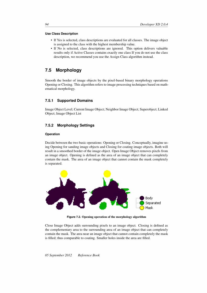
94 Developer XD 2.0.4
Use Class Description
• If Yes is selected, class descriptions are evaluated for all classes. The image objectis assigned to the class with the highest membership value.
• If No is selected, class descriptions are ignored. This option delivers valuableresults only if Active Classes contains exactly one class If you do not use the classdescription, we recommend you use the Assign Class algorithm instead.
7.5 Morphology
Smooth the border of image objects by the pixel-based binary morphology operationsOpening or Closing. This algorithm refers to image processing techniques based on math-ematical morphology.
7.5.1 Supported Domains
Image Object Level; Current Image Object; Neighbor Image Object; Superobject; LinkedObject; Image Object List
7.5.2 Morphology Settings
Operation
Decide between the two basic operations: Opening or Closing. Conceptually, imagine us-ing Opening for sanding image objects and Closing for coating image objects. Both willresult in a smoothed border of the image object. Open Image Object removes pixels froman image object. Opening is defined as the area of an image object that can completelycontain the mask. The area of an image object that cannot contain the mask completelyis separated.
Figure 7.2. Opening operation of the morphology algorithm
Close Image Object adds surrounding pixels to an image object. Closing is defined asthe complementary area to the surrounding area of an image object that can completelycontain the mask. The area near an image object that cannot contain completely the maskis filled; thus comparable to coating. Smaller holes inside the area are filled.
05 September 2012 Reference Book
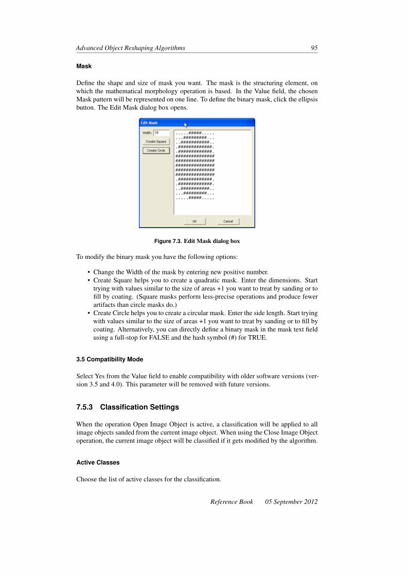
Advanced Object Reshaping Algorithms 95
Mask
Define the shape and size of mask you want. The mask is the structuring element, onwhich the mathematical morphology operation is based. In the Value field, the chosenMask pattern will be represented on one line. To define the binary mask, click the ellipsisbutton. The Edit Mask dialog box opens.
Figure 7.3. Edit Mask dialog box
To modify the binary mask you have the following options:
• Change the Width of the mask by entering new positive number.• Create Square helps you to create a quadratic mask. Enter the dimensions. Start
trying with values similar to the size of areas +1 you want to treat by sanding or tofill by coating. (Square masks perform less-precise operations and produce fewerartifacts than circle masks do.)
• Create Circle helps you to create a circular mask. Enter the side length. Start tryingwith values similar to the size of areas +1 you want to treat by sanding or to fill bycoating. Alternatively, you can directly define a binary mask in the mask text fieldusing a full-stop for FALSE and the hash symbol (#) for TRUE.
3.5 Compatibility Mode
Select Yes from the Value field to enable compatibility with older software versions (ver-sion 3.5 and 4.0). This parameter will be removed with future versions.
7.5.3 Classification Settings
When the operation Open Image Object is active, a classification will be applied to allimage objects sanded from the current image object. When using the Close Image Objectoperation, the current image object will be classified if it gets modified by the algorithm.
Active Classes
Choose the list of active classes for the classification.
Reference Book 05 September 2012
96 Developer XD 2.0.4
Erase Old Classification If There Is No New Classification
• If you select Yes and the membership value of the image object is below the accep-tance threshold (see classification settings) for all classes, the current classificationof the image object is deleted.
• If you select No and the membership value of the image object is below the accep-tance threshold (see classification settings) for all classes, the current classificationof the image object is kept.
Use Class Description
• If Yes is selected, class descriptions are evaluated for all classes. The image objectis assigned to the class with the highest membership value.
• If No is selected, class descriptions are ignored. This option delivers valuableresults only if Active Classes contains exactly one class
If you do not use the class description, we recommend you use the Assign Class algorithminstead.
7.6 Watershed Transformation
Calculate an inverted distance map based on the inverted distances for each pixel to theimage object border. Afterwards, the minima are flooded by increasing the level (inverteddistance). Where the individual catchment basins touch each other (watersheds), theimage objects are split.
The watershed transformation algorithm is commonly used to separate image objectsfrom others. Image objects to be split must already be identified and classified.
7.6.1 Supported Domains
Image Object Level; Current Image Object; Neighbor Image Object; Superobject; LinkedObject; Image Object List
7.6.2 Watershed Settings
Length Factor
The Length factor is the maximal length of a plateau, which is merged into a catchmentbasin. Use the toggle arrows in the Value field to change to maximal length. The LengthFactor must be greater or equal to zero.
7.6.3 Classification Settings
Define a classification to be applied if an image object is cut by the algorithm.
05 September 2012 Reference Book

Advanced Object Reshaping Algorithms 97
Active Classes
Choose the list of active classes for the classification.
Erase Old Classification If There Is No New Classification
• If you select Yes and the membership value of the image object is below the accep-tance threshold (see classification settings) for all classes, the current classificationof the image object is deleted.
• If you select No and the membership value of the image object is below the accep-tance threshold (see classification settings) for all classes, the current classificationof the image object is kept.
Use Class Description
• If Yes is selected, class descriptions are evaluated for all classes. The image objectis assigned to the class with the highest membership value.
• If No is selected, class descriptions are ignored. This option delivers valuableresults only if Active Classes contains exactly one class
If you do not use the class description, we recommend you use the Assign Class algorithminstead.
Reference Book 05 September 2012


8 Pixel-Based ObjectReshaping Algorithms
Pixel-based reshaping algorithms modify the shape of image objects by adding or remov-ing pixel/voxels according to given criteria.
8.1 Pixel-Based Object Resizing
Grow or shrink image objects based on pixel criteria. Typically, the Relative Area ofClassified Objects feature is used to find suitable seed image objects. These are grownor shrunken to larger or smaller image objects. In addition you can use this algorithm tosmooth the surface of image objects by growing or shrinking. You can choose to resizein one, two or three dimensions.
8.1.1 Supported Domains
Image Object Level; Current Image Object; Neighbor Image Object; Super Object; SubObjects; Linked Objects; Image Object List
8.1.2 Algorithm Parameters
Resizing modes
Growing Grow each seed image object. The starting extents of the seed image objectsare lost.
Figure 8.1. Sample starting classification (left) and after 10x growing (right)
99

100 Developer XD 2.0.4
Coating Add an new image object around each seed image objects and grows it. Theseed image objects continue to exist as separate image objects with unchanged extent.
Figure 8.2. Sample starting classification (left) and 10x coating (right). Coating works fromoutside the Candidate image objects to the center
Shrinking Add an new image object inside each candidate image objects and grows it. Acandidate image object shrinks by the extent of the new image object. This mode workssimilar like coating, but inside of candidate image objects.
Figure 8.3. Sample starting classification (left) and after 10x shrinking (right). Shrinkingworks from outside the Candidate image objects to the center
Class for New Image Objects
Select a class to be assigned to the new image objects. This feature is available forCoating or Shrinking modes, but not for Growing.
Preserve Current Object Type
Select the type of image object to determine how image objects of the target class aremerged.
Value Description
Yes Newly created image objects are 2D-connected. Other image objects maintain theirconnectivity (default)
No Newly created image objects are disconnected. Any overwritten objects or splitsub-objects are disconnected.
05 September 2012 Reference Book
Pixel-Based Object Reshaping Algorithms 101
8.1.3 Candidate Object Domain Parameters
Define the set of neighboring image objects whose pixels are considered for growing. Apixel can be only added to an image object that is part of the candidate object domain.This feature is available for Coating or Shrinking modes, but not for Growing.
Class Filter
Select a candidate class. Image objects that are selected in the image object domain areautomatically excluded from the candidates.
Threshold Condition
Define an additional threshold condition to define the candidate image object domain.Only pixels that belong to image objects that fulfill the threshold condition are consideredfor resizing.
8.1.4 Pixel Level Constraint Parameters
Pixel Layer Constraint 1; Pixel Layer Constraint 2
In addition, you can define one or two independent image layer intensity conditions to befulfilled by candidate pixels on a given image layer. The candidate pixels are only addedto the set of active pixels if the conditions defined are fulfilled.
Layer
Select any image layer to be used for the pixel layer constraint.
Operation
Select a comparison operation to be executed. An image layer must be selected.
Value Description
< Less than. (Default)
<= Less than or equal to
= Equal to
> Greater than
>= Greater than or equal to
Reference Book 05 September 2012

102 Developer XD 2.0.4
Reference
Select the type of value used for comparing to the pixel layer intensity value. An imagelayer must be selected
Value Description
Absolute value Compare with an absolute layer intensity value that you can define; see Valuebelow. It also can be represented by a variable.
Value ofcurrent pixel
Compare with the layer intensity value of the current pixel. You can define aTolerance, see below.
Value
Enter a layer intensity value used as threshold for the comparison operation. Alternatively,you can select a feature or a variable. To create a new variable, type a name for the newvariable and click OK to open the Create Variable dialog box for further settings. Anabsolute value has to be selected as a reference option.
Tolerance
Enter a value used as tolerance for the threshold Value of the comparison operation. Thevalue of the current pixel has to be selected as a reference option. Alternatively, you canselect a feature or a variable.
Tolerance Mode
Select a calculation mode for the Tolerance value of the threshold value of the comparisonoperation. The value of the current pixel must be selected as a reference option.
Value Description
Absolute The Tolerance value represents a percentage value. For example, 20 means atolerance of 20 gray values.
Percentage The Tolerance value represents a percentage value. For example, 20 means atolerance of 20% of the threshold value.
8.1.5 Candidate Surface Tension Parameters
Use surface tension options to smooth the border of the resizing object.
Additionally, you can edit the settings so that the shapes of image objects are smoothedwith no significant growing or shrinking.
Surface tension uses the Relative Area of Classified Objects region feature of pixels of agiven class to optimize the image object shape while resizing. Within a cube of given size
05 September 2012 Reference Book

Pixel-Based Object Reshaping Algorithms 103
Figure 8.4. Sample classification after 10x growing without (left) and with (right) surfacetension
Figure 8.5. Sample classification after 10x coating without (left) and with (right) surfacetension
(figure 8.8) around the current candidate pixel, the ratio of relative area of seed pixels toall pixels inside the box is calculated.
If the result is according to a given comparison operation (figure 8.9) with a given value,the current candidate is classified as seed; otherwise it keeps its current classification.
Reference
Choose to use either seed pixels of a current image object or pixels of a given class forsurface tension calculation. Your choice influences smoothing while resizing.
None Surface tension is not active.
Object Surface tension is calculated based on image objects: Within the calculation box,only pixels of the candidate image objects are mentioned. This allows you to smooththe border of each seed image object without taking neighbor seed image objects intoaccount.
Figure 8.6. Sample classification after 10x shrinking without (left) and with (right) surfacetension
Reference Book 05 September 2012
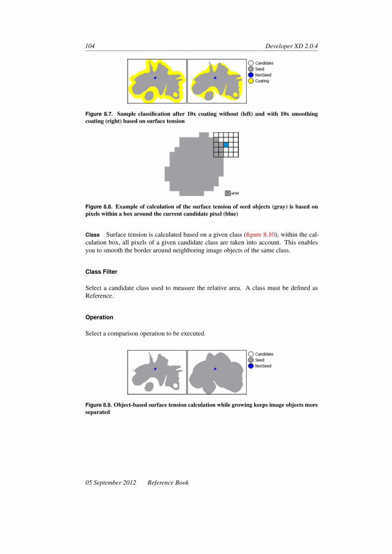
104 Developer XD 2.0.4
Figure 8.7. Sample classification after 10x coating without (left) and with 10x smoothingcoating (right) based on surface tension
Figure 8.8. Example of calculation of the surface tension of seed objects (gray) is based onpixels within a box around the current candidate pixel (blue)
Class Surface tension is calculated based on a given class (figure 8.10); within the cal-culation box, all pixels of a given candidate class are taken into account. This enablesyou to smooth the border around neighboring image objects of the same class.
Class Filter
Select a candidate class used to measure the relative area. A class must be defined asReference.
Operation
Select a comparison operation to be executed.
Figure 8.9. Object-based surface tension calculation while growing keeps image objects moreseparated
05 September 2012 Reference Book

Pixel-Based Object Reshaping Algorithms 105
Figure 8.10. Class-based surface tension calculation while growing smooths multiple imageobjects of a class
Value Description
>= Greater than or equal to (default)
< Less than
<= Less than or equal to
= Equal to
> Greater than
Value
Enter a value for the surface tension calculation. Alternatively, you can select a featureor a variable. To create a new variable, type a name for the new variable and click OK toopen the Create Variable dialog box for further settings.
Box Size in X and Y
Enter the pixel size of the square box around the current candidate pixel in x - and y-directions to use for the surface tension calculation. The integer value must be uneven;even integer values are changed to the next higher integer. You can enter a value as athreshold. Alternatively, you can select a feature or a variable. To create a new variable,type a name for the new variable and click OK to open the Create Variable dialog box forfurther settings. The default value is 5.
Box Size in Z
Similar to Box Size in X and Y. The default value is 1.
8.1.6 Size Limits Parameters
These parameters limit the sizes of growing and shrinking operations.
Min Object Size
The Minimum Object Size parameter stops an object shrinking when it reaches a mini-mum size. It is very useful for preventing a shrinking object from disappearing (that isattaining a size of zero).
Reference Book 05 September 2012

106 Developer XD 2.0.4
Max Object Size
The Maximum Object Size parameter stops an object from growing when it reaches amaximum size. It is very useful for preventing a growing object from ‘leaking’.
8.2 Pixel-Based Density Filter
Create new classified image objects from pixel/voxels of image objects in the image ob-ject domain according to the class density in the surroundings. You can use this algorithmto smooth the shape of image objects by removing protrusions.
The class density calculation is based on the Relative Area of Classified Objects Regionfeature of pixel/voxels of a given class. For each candidate pixel/voxel of image objectsin the image object domain, a cubic box of given size is used to calculate the ratio ofrelative area of classified pixel/voxels to all pixel/voxels inside the box.
Figure 8.11. Example of calculation of the class (gray) density is based on pixels within a boxaround a candidate pixel (blue)
If the class density is according to given comparison operations with a given value thecurrent candidate pixel/voxel is classified as target class, otherwise it keeps its currentclassification. Image objects of the target class are merged with each execution of thealgorithm.
8.2.1 Supported Domains
Image Object Level; Current Image Object; Neighbor Image Object; Super Object; SubObjects; Linked Objects; Image Object List
8.2.2 Algorithm Parameters
Target Class
Select a class to be assigned to image objects according to density criteria on page 108.
Preserve Current Object Type
Select the type of image object to determine how image objects of the target class aremerged.
05 September 2012 Reference Book

Pixel-Based Object Reshaping Algorithms 107
Value Description
Yes Newly created image objects are 2D-connected. Other image objects maintain theirconnectivity (default)
No Newly created image objects are disconnected. Any overwritten objects or splitsub-objects are disconnected.
8.2.3 Growing and Shrinking Directions Parameters
Growing can be enabled or disabled for each dimension. It can also be partially enabledso that growing occurs towards positive or negative co-ordinates only.
Figure 8.12. Growing directions for two dimensions
X, Y and Z Directions
Define the search order around active pixels. You can do this for each co-ordinate axisseparately:
Value Description
Yes Enable resizing.(Default for x and y -directions.)
Only Positive Restrict resizing in direction of positive co-ordinates only.
Only Negative Restrict resizing in direction of negative co-ordinates only.
No Disable resizing. (Default for z -direction.)
Balance Growing Directions by Pixel Size
If you work with a three-dimensional scene that has a different voxel size for the z-direction compared to the x - and y -directions, you can choose to take the voxel reso-lution into account. This ensures that image objects are resized evenly in all directions.Resizing must be enabled for z -direction.
Reference Book 05 September 2012

108 Developer XD 2.0.4
Figure 8.13. Example of 10x growing in x -direction is restricted to the positive direction andin y -direction to the negative direction
Value Description
No Growing is performed in all directions with the same preference.
Yes In this case the growing takes the extension of the voxel into account. For eachgrowing step in the z direction the number of growing steps in the xy direction equalsthe ratio of the voxel dimensions, for example the xy extend to z extend.
8.2.4 Density Criteria Parameters
You can define one to three independent density criteria that need to be fulfilled by candi-date pixel/voxels on a given image layer. Only if all criteria are fulfilled is the candidatepixel/voxel classified.
Reference
To activate a density criterion, select whether pixel/voxels of a current image object orpixel/voxels of a given class are used for class density calculation. That way, you influ-ence the way of smoothing while resizing:
Value Description
None Density criterion is not active. (Not available for Density Criterion 1)
Object Class density is calculated based on the image object that contains the currentcandidate pixel/voxel. Within the calculation box, only pixel/voxels of this imageobject, are mentioned. This allows you to smooth the border of the image objectwithout taking neighbor image objects into account.
Class Class density is calculated based on a given class (see below). Within the calculationbox, all pixel/voxels of the given class are taken into account. This allows you tosmooth the border around neighboring image objects of the same class.
Class Filter
Select a candidate class to use for calculation of class density. A class must be defined asReference.
05 September 2012 Reference Book

Pixel-Based Object Reshaping Algorithms 109
Operation
Select a comparison operation to be executed:
Value Description
>= Greater than or equal to. (Default)
< Less than
<= Less than or equal to
= Equal to
> Greater than
Value
Enter a value, or select a feature, or a variable used a threshold for the class densitycalculation. To create a new variable, type a name for the new variable and click OK toopen the Create Region Variable dialog box for further settings.
Box Size in X and Y
Enter the pixel/voxel size of the square box around the current candidate pixel/voxel in xand y -directions, used for the class density calculation. The integer value must be an oddnumber; even-numbered integer values are changed to the next higher integer.
You can enter a value, or select a feature, or a variable used as threshold. To create anew variable, type a name for the new variable and click OK to open the Create RegionVariable dialog box for further settings. The default value is 1.
Box Size in Z
Similar to Box Size in X and Y. The default value is 1.
8.3 Pixel-Based Shape Processing Filters
Provides a set of different filters for processing image objects with respect to variousshape criteria:
Reference Book 05 September 2012

110 Developer XD 2.0.4
Filter Description
Pixel Count Detects and modifies low-level pixel patterns.
Corner Pixels Detects the corner pixel of an image object. In conjunction with the Connect filter, itcan be used to cut image objects according to their shape.
Connect Creates a pixel connection between two linked image objects. Can be used toconnect pixels detected by the Corner Pixels or Hole Cutting Pixels filter and thus tocut image objects.
Inner Border Reclassifies all pixels at the inner border of an image object.
Outer Border Reclassifies all pixels at the outer border of an image object.
HoleCuttingPixels
Detects pairs of pixels at the inner and outer borders of image objects. Inconjunction with the Connect filter, it can be used to cut holes out of image objects.
8.3.1 Supported Domains
Image Object Level; Current Image Object; Neighbor Image Object; Super Object; SubObjects; Linked Objects
8.3.2 Algorithm Parameters
Target Class
Select a class to be assigned to the processed pixels.
Preserve Current Object Type
Select Yes or No:
Value Description
Yes Ensures that the image object type of processed image objects does not change due topixel removal.
No Changes the type of all modified image objects to disconnected, regardless of theircurrent state. You can use the Convert Image Objects algorithm (p 82) to make sureprocessed image objects are assigned the desired image object type after processing.
Filter Type
Select a filter.
05 September 2012 Reference Book

Pixel-Based Object Reshaping Algorithms 111
Pixel Count The Pixel Count filter detects basic pixel patterns in the 4-neighborhood ofa pixel and reclassifies all pixels in the domain where a pattern occurs. It can be usefulto connect border pixels to a 4-connected structure or to detect pixel bridges in imageobjects. In addition to the basic parameters mentioned above, you can set the followingparameters:
Corner Pixels The Corner Pixels filter detects the corners of an image object specifiedby the image object domain. The detected corners can be concave or convex.
The filter enables you to further connect detected concave corner pixels using imageobject links. In conjunction with the Connect filter mode, these connections can be usedto create lines along which the image objects can be cut according to their shape. Inaddition to the basic parameters mentioned above, you can set the following parameters:
Connect The Connect filter creates a pixel line between two linked image objects. Itchecks all image objects specified in the image object domain for image object links toanother image object. If an image object link exists, it creates a one pixel line betweenthe two image objects according to the filter parameters and deletes the image object link.
This mode is specifically designed to be used in conjunction with the Corner Pixel filterdetection of concave corners.
In addition to the basic parameters mentioned above, you can set the following parame-ters:
• Candidate Class Filter specifies a class filter for candidate objects. Only pixels thatbelong to an object of one of the specified classes will be taken into account for theconnection
• Exclude Border Pixels1 specifies whether pixels located at the border of areas de-fined by the Candidate Class Filter parameter are taken into account for the connec-tion:
– If the value is Yes, border pixels are not taken into account– If the value is No, all pixels of the specified areas are taken into account
• Distance Mode specifies how distances between two pixels are calculated:– Spatial Distance determines the shortest connection along the candidate pix-
els that can be found between two image objects. Uses predefined values1 for 4-connected pixels and 2 for diagonally connected pixels to calculatepixel distance
– Color Contrast determines the shortest connection along the candidate pixelsthat can be found between two image objects. Uses the difference between thepixel intensities of two pixels for an image layer to calculate pixel distance.
• Image Layer specifies the layer used to calculate pixel distances. It is only availableif the Distance Mode parameter is set to Color Contrast
Inner Border The Inner Border filter reclassifies all neighboring pixels of an image ob-ject that touch an inner border of the object. This filter is useful to detect holes withinimage objects. There are no additional parameters for this filter.
1. If you enable the Exclude Border Pixels parameter, it might not be possible to establish a valid connectionbetween two image objects. To avoid endless loops or other unwanted effects, make sure that the rule set youuse can handle this situation properly.
Reference Book 05 September 2012

112 Developer XD 2.0.4
Figure 8.14. Result of Inner Border filter processing
Outer Border The Outer Border filter reclassifies all neighboring pixels of an imageobject that touch the outer border of the object. There are no additional parameters forthis filter.
Figure 8.15. Result of Outer Border filter processing
Hole Cutting Pixels The Hole Cutting Pixels filter detects inner border pixels with closeproximity to the outer border and related pixels on the outer border.
Figure 8.16. Result of Hole Cutting Pixels filter processing
Both pixels are linked so that you can use the Connect filter to cut out so-detected innerholes from the object. In order to avoid structures that are quite similar to a nearly closedhole the filter always detects two pairs of inner and outer pixels that have a maximumdistance to each other.
05 September 2012 Reference Book

Pixel-Based Object Reshaping Algorithms 113
Figure 8.17. Result of subsequent Connect filter processing
Mode Parameters
Corner Type Specify the type of corner pixels to search for:
Value Description
Concave Detects and reclassifies concave corner pixels.
Convex Detects and reclassifies convex corner pixels.
All Detects and reclassifies both concave and convex corner pixels.
Figure 8.18. Image object (left) and its results after detection of concave (middle) and convex(right) corner pixels
Leg Length For each border pixel, the filter analyzes the angle of the border by creatingan angle between the pixel and the adjacent border pixels to the left and to the right. Theleg length describes the length of the angle legs in border pixels. Increase the leg lengthvalue to apply a smoothening to the real image object border. Typical values lie withinthe range 2 to 9.
Minimum Angle Specify the minimum angle (based on the leg length) that must bepresent at a border pixel so that it will be considered as a corner.
If you enter a value of 0°, every border pixel with an angle different to 180° is consideredas a potential corner. The larger the value, the more acute the minimum angle that isneeded for a corner to be accepted.
Reference Book 05 September 2012

114 Developer XD 2.0.4
Figure 8.19. Angle measurement at a border pixel with leg length 3 pxls (approx. 45° for aconcave corner pixel)
Connect Corners for Cutting This parameter is only available if Corner Type parameteris set to Concave. It lets you specify whether detected corners are to be connected usingimage object links:
Value Description
Yes Does not connect corners using image object links.
No Detects and connects matching corners using image object links. The connections canbe used as input for further processing with the Connect filter. Unconnected corners arenot instantiated.
Max. Cut Length This parameter is only available if Corner Type parameter is set toConcave and if Connect Corners for Cutting parameter is set to Yes.
Specify the maximum length of the direct connection between two corner pixels. Cornersare only be linked for connection if their distance is below this threshold. Values aremeasured in pixels. A value of 0 will disable this restriction.
Cut Length/Border Length This parameter is only available if Corner Type parameter isset to Concave and if Connect Corners for Cutting parameter is set to Yes. Specify themaximum ratio of the direct distance between two corners and the distance along theobject border. Corners are only linked for connection if the ratio is below this threshold.
Values must lie within the range 0 to 1. A value of 1 will link all corner pairs, a value of0 will reject all corner pairs.
The example below shows the result of concave corner pixel detection with a leg lengthof 3 and a minimum angle of 35°. The Connect Corners for Cutting parameter is set toYes; a cut length/border length ratio of up to 0.3 is allowed.
The selected pixel objects (marked in red and green) are connected using an image objectlink.
Reference Specify the reference for pixel pattern detection:
05 September 2012 Reference Book

Pixel-Based Object Reshaping Algorithms 115
Figure 8.20. Result of Pixel Corner Pixels filter processing with the settings described above
Value Description
Object Detects patterns of pixels within the same object.
Class Detects patterns of pixels assigned to the same class.
Class Filter This parameter is only available if Reference parameter is set to Class. Spec-ify the class filter used for pixel pattern detection in Class reference mode.
Pixel Pattern Specify the pattern of target pixels to search for:
Table 8.-14. Pixel Pattern Settings
Value Description
0 No neighboring pixels. Reclassifies isolated pixels
1 Exactly one neighboring pixel. Reclassifies end points of lines with awidth of one pixel
2 Exactly two neighboring pixels. Combines the reclassification results of 2(angle) and 2 (line) modes
2 (angle) Exactly two neighboring pixels forming an angle with the center pixel.Reclassifies pixels that are part of a diagonal pixel bridge. Use this modeto convert 8-connected pixel structures into 4-connected pixel structures
2 (line) Exactly two neighboring pixels forming a line with the center pixel.Reclassifies pixels (except end points) being part of lines with a width ofone pixel
3 Exactly three neighboring pixels
4 Exactly four neighboring pixels. Reclassifies pixels that are completelysurrounded by target pixels
The example below shows the result of a pixel count filter processing on the blue areausing the 2 (angle) pixel pattern. The orange pixels are used as a reference.
Reference Book 05 September 2012

116 Developer XD 2.0.4
Figure 8.21. Result of Pixel Count filter processing with the settings described in table 8.-14on the preceding page, Pixel Pattern Settings
In the course of pixel processing, the orange pixel structure is converted into a 4-connected structure that can be merged into one connected image object.
Candidate Class Filter Class filter for candidate objects. Only pixels that belong to anobject of one of the specified classes will be considered for the shortest path.
Exclude Border Pixels When this option is set to yes, the connection must not go alongpixels at the border of the selected class
Search in Z Direction Search also in Z direction (3D images only)
Distance Mode Select the way pixel distances are computed using spatial distance, colorcontrast or color value.
05 September 2012 Reference Book

9 Linking OperationAlgorithms
Use linking operations algorithms to work with image object links. Image object links canbe used to group multiple image objects in different areas of the image without creatinga common superobject.
9.1 Create Links
This algorithm allows you to create and establish object links between image objects.
Figure 9.1. Overlap calculations of the Create Links algorithm
For z = 1 slices, n and n + 1 are scanned and some overlap area is determined. Usuallyparameters x,y and t are zero. It may be useful to have values different from zero ifstructures such as blood vessels or time series are to be analyzed. For x,y, t 6= 0 , theoverlap region gets calculated with respect to the shifted template.
9.1.1 Supported Domains
Image Object Level; Current Image Object; Neighbor Image Object; Superobject; Sub-objects; Linked Objects; Image Object List
117

118 Developer XD 2.0.4
9.1.2 Algorithm Parameters
Link Class
Select a class that will be assigned to the new links. This class represents the group nameof the links and is used to compute statistics of the image objects belonging to this linkclass.
9.1.3 Candidate Object Domain Parameters
Class Filter
Specify for the classes of candidate image objects to be linked with the seed image ob-jects.
Threshold Condition
Specify an additional condition for candidate objects. Only image objects meeting thespecified condition will be considered for linking.
Map
You can specify a different map to the map selected in the image object domain. In thiscase, image object links between different maps will be created. This can be useful toexpress object relations between maps.
Candidate PPO
Select the PPO level to use for the objects from the next parent process. This parameteris only valid if domain and candidate maps are the same.
9.1.4 Overlap Settings Parameters
These parameters are used to specify the shift in space and time from the seed object todetermine the position of objects to that will be linked.
Link To
• Use ‘all’ to link to all objects that match the conditions• Use ‘best’ to create the link only to the candidate object that has the largest overlap
in the set of all possible overlapping objects.
05 September 2012 Reference Book

Linking Operation Algorithms 119
Overlap Calculation
Select one of the following options:
Value Description
Do not use overlap Overlap calculation is omitted. Link is created to any object matching thetarget conditions
Relative to largerobject
The ratio of the overlap area to the area of the larger object (between seedand target object) is calculated
Relative to smallerobject
The ratio of the overlap area to the area of the smaller object is calculated
Relative to currentobject
The ratio of the overlap area to the area of the current objects is calculated
Relative tocandidate object
The ratio of the overlap area to the area of the candidate objects iscalculated
Absolute [in pixels] The absolute overlap area in pixels is calculated
X-Position Shift
Shift in pixels in the x direction (± integer values).
Y-Position Shift
Shift in pixels in the y direction (± integer values).
Z-Position Shift
Shift in pixels in the z direction (± integer values).
T-Position Shift
Shift in pixels in the t direction (± integer values).
Min. Required Overlap
Lower threshold for image object overlap. A link will only be created if the calculatedoverlap will exceed the specified threshold. Use 0 to disable this parameter.
• If the overlap calculation is set to Do Not Use Overlap, Min. Required Overlap isnot available
• If the overlap calculation is set to Absolute [in pixels], enter any integer• If the overlap calculation is set to any other option, enter a percentage represented
by a float number between 0 and 1.
Reference Book 05 September 2012

120 Developer XD 2.0.4
Figure 9.2. Incoming and outgoing links over multiple time frames. The red circles representobjects and the green arrows represent links
Transformation Parameter Set
This parameter is only available if the map specified in the image object domain is differ-ent to the map specified in the candidate object domain.
If you don’t know the transformation parameters, you can use the Image Registrationalgorithm to perform an automatic affine registration and store the transformation matrixin a parameter set. Using this transformation information, you can then link objects thatrelate to each other in the original maps.
9.2 Delete Links
Delete all or selected object links. The parameters of this algorithm can be used to filterout specific links to be deleted. All parameters are cumulative; only links fulfilling allspecified criteria will be deleted.
9.2.1 Supported Domains
Image Object Level; Current Image Object; Neighbor Image Object; Super Object; SubObjects; Linked Objects; Image Object List
9.2.2 Algorithm Parameters
Link Class Filter
Classification filter for links to delete. Only links grouped under the selected classes willbe deleted.
Class Filter
Classification filter for linked image objects. Only links that link to an object of one ofthe selected classes will be deleted.
05 September 2012 Reference Book

10 Level Operation Algorithms
Level operation algorithms enable you to add, remove, or rename entire image objectlevels within the image object hierarchy.
10.1 Copy Image Object Level
Insert a copy of the selected image objects domain above or below the existing one.
10.1.1 Supported Domains
Image Object Level
10.1.2 Algorithm Parameters
Level Name
Enter the name for the new image object level.
Copy Level
Select whether the copied level is placed above or below the input level specified by thedomain.
10.2 Delete Image Object Level
Delete the image object level selected in the image object domain.
10.2.1 Supported Domains
Image Object Level
121

122 Developer XD 2.0.4
10.3 Rename Image Object Level
Rename an image object level.
10.3.1 Supported Domains
Execute
10.3.2 Algorithm Parameters
Level to Rename
Select the image object level to be renamed.
New Level Name
Select or edit an image object level to be changed, and select or edit the new name for thelevel. If the new name is already assigned to an existing level, that level will be deleted.This algorithm does not change names already existing in the process tree.
05 September 2012 Reference Book

11 Map Operations Algorithms
Map operations algorithms are used for working with multiple maps and can be used forthe following actions:
• Local storage of temporary results• Multi-scale image analysis and other workspace automation techniques, which en-
able you to process image data without using the Definiens Server• Comparison of competing and concurrent analysis strategies on the same image
data in parallel. This enables you to select the best results from each analysis andcombine them into a final result
• Comparison of results on different sets of image data in parallel. This enhancesinteractive training approaches and helps to develop robust ruleware.
11.1 Copy Map
Copy a map, or part of a map – such as current image object – to a new map, or overwritean existing map with the copy. 2D, 3D and 4D maps can be copied; the minimum size ofa map to be created is 4×4 pixels.
11.1.1 Supported Domains
Execute; Current Image Object; Neighbor Image Object; Super Object; Sub Objects;Linked Objects
11.1.2 Algorithm Parameters
Source Region
Define a region within the source map. Select or enter the name of an existing re-gion. Alternatively, you can enter the co-ordinates of a region specified by its origin(xG,yG) , which is the lower left corner , and its size [Rx,Ry,Rz,Rt ] . The input pattern is(xG,yG,zG, tG) , [Rx,Ry,Rz,Rt ] .
Alternatively, you can select a variable. To create a new variable, type a name for the newvariable and click OK or press Enter to open the Create Variable dialog box for furthersettings.
123

124 Developer XD 2.0.4
Target Map Name
The map to be created by copying. Select a map name from the drop-down list or entera new name. If you select an existing map, the copy will overwrite it. Alternatively, youcan create a map variable.
Use Variable As Scale
Specify the scale for copying a map using a variable, rather than defining a numericalvalue.
Scale
Figure 11.1. Select Scale dialog box
If you choose to resample, the Scale will refer to the original image data. If you choosethe default Use Current Scene Scale, the map copy will have the same scale as the map(or part of a map) being copied. For example, if the main map is copied to map2 with theScale at 50%, and map2 is copied to map3 with the Scale at 50%, map3 will be scaled to50% of the main map, and not 50% of map2:
1. If you do not want to keep the current scale of the map for the copy, click theellipsis button to open the Select Scale dialog box.
2. Selecting a scale different to the current scene scale lets you work on the map copyat a different magnification/resolution.
3. If you enter an invalid scale factor, it will be changed to the closest valid scale asdisplayed in the table below.
4. To change the current scale mode, select from the drop-down list. We recommendthat you use the scaling mode consistently within a rule set as the scaling resultsmay differ. Scaling results can differ depending on the scale mode; for example ifyou enter 40, you work at the following scales, which are calculated differently:
05 September 2012 Reference Book

Map Operations Algorithms 125
Options dialog box setting Scale of the scene copy or subset to be created
Units (m/pixel) 40m per pixel
Magnification 40x
Percent 40% of the resolution of the source scene
Pixels 1 px per 40 px of the source scene
Clockwise Rotation Angle
This feature lets you rotate a map that you have copied, by a fixed value or with respectto a variable.
Resampling
Choose whether to apply Gaussian smoothing:
Value Description
Smooth Smoothing is applied. If smoothing is applied and downsampling occurs, thealgorithm generates smoothed .tif files next to the project file (.dpr)
Fast Smoothing is not applied. Select for faster processing.
Image Layers
Select an image layer to use in the new map. If no layer is selected, all will be used.Layers are copied if downsampling occurs and Smooth is selected in the Resamplingfield.
Copy Thematic Layers
Select a thematic layer to use in the new map. If no layer is selected, all will be used. The-matic vector layers are always copied and converted to thematic raster layers. Thematicraster layers are copied if downsampling occurs and Smooth is selected in the Resamplingfield.
Copying thematic vector layers can be performance-intensive because vector layers areconverted to raster layers.
Thematic Layers
You may specify a thematic layer to use; if no layer is selected, all layers will be used.
Reference Book 05 September 2012

126 Developer XD 2.0.4
Copy Image Object Hierarchy
Choose whether the image object hierarchy is copied with the map or not:
• If Yes is selected, the image object hierarchy of the source map will be copied tothe new map.
• If No is selected, only selected image and thematic data will be copied to the newmap.
Preserve Current Object Type
When this option is set to No, then created objects can be unconnected, so one object canhave more than one polygon.
Visiblity Flag
If the value is set to Yes (the default), all maps are available from the map drop-down box.If it is set to No, the created map can be accessed, but cannot be displayed.
Compatibility Mode
Allows compatibility with previous software versions.
Scale Direction
Choose from one of the following:
• Plane only• Plane and z• Plane and time• All directions
11.2 Delete Map
Delete a specified map or maps. There are no algorithm parameters.
11.2.1 Supported Domains
Execute; Maps
11.3 Synchronize Map
Copy image objects from one map to another.
05 September 2012 Reference Book

Map Operations Algorithms 127
11.3.1 Supported Domains
Image Object Level
11.3.2 Algorithm Parameters
Target Map Name
Required. Use the dropdown list to select an existing map or map variable, or create anew map variable and assign a value to it.
Region
Define a target region to which image objects are copied. Select or enter the name of anexisting region. Alternatively, you can enter the co-ordinates of a region specified by itsorigin (xG,yG) , which is the lower left corner , and its size [Rx,Ry,Rz,Rt ] . The inputpattern is (xG,yG,zG, tG) , [Rx,Ry,Rz,Rt ] . Alternatively, you can select a variable. Tocreate a new variable, type a name for the new variable and click OK or press Enter toopen the Create Variable dialog box for further settings.
Alternatively, you can create a region by entering numbers with that exact syntax: (originx , origin y ) - (extent x , extent y ); for example (10,20) - (100,110).
Level
Required. Select the target image object level in the target map.
Class Filter
Select objects of classes on the target map (these can be overwritten). Click the ellipsisbutton to open the Edit Classification Filter dialog box. The default is none, which meansobjects of any class can be overwritten.
Threshold Condition
Select a threshold condition. Image objects matching the threshold will be overwritten.Click the ellipsis button to open the Select Single Feature dialog box. The default is none,which means objects of any class can be overwritten.
Clockwise Rotation Angle
This feature lets you rotate a map that you have synchronized, by a fixed value or withrespect to a variable. If you have rotated a copied map using the Copy Map algorithm,you can restore it with the Synchronized Map algorithm by using the negative value ofthe angle of rotation.
Reference Book 05 September 2012

128 Developer XD 2.0.4
Preserve Current Object Type
• If Yes is selected, the current object type is preserved for all affected objects• If No is selected, modified objects can become disconnected objects.
Synchronize Complete Hierarchy
When this option is set to yes, then all levels on the target map will be affected.
11.4 3D/4D Settings
Define the map layout settings for multidimensional data sets.
Because Definiens software handles multidimensional data sets internally as a two-dimensional image, you have to define how these two-dimensional maps represent thecorresponding data set.
11.4.1 Supported Domains
Execute
11.4.2 Algorithm Parameters
Mode
Select a mode:
Mode Description
Noninvasive The map size in x is assumed to be the 2D slice size in x and y. This is used tocompute the number of slices.
Example: Imagine a map with the size 256×1024. The noninvasive mode uses themap size x=256 to determine the slice size y=256. Thus, the map is handled as a3D map consisting of 1024/256=4 slices of size 256×256 each.
2D extent Enter the size of a single slice or a single frame; see below.
4D layout Depending on the data set, you can enter the number of slices and the number offrames; see below.
Slice/Frame Size X & Y
Depending on the dataset, enter the x and y sizes per single slice or frame. (2D Extentmust be selected.)
05 September 2012 Reference Book

Map Operations Algorithms 129
Number of Slices
Enter the number of slices of the data set. (4D Layout must be selected.)
Number of Frames
Enter the number of frames of the data set. (4D Layout must be selected.)
Distance Between Slices
Enter the distance between slices the distance you enter is relative to the xy resolution.The default is 0.5. For example:
• Slice Distance 1 means x = y = z = 1• Slice Distance 2 means 2x = 2y = 1z• Slice Distance 0.5 means x = y = 0.5z
Time Between Two Frames
Enter the time elapsing between frames. The default is 0.5.
Co-ordinate of the First Slice
Enter the co-ordinate of the first slice, which determines the co-ordinates of other slices.The default is 0.
Start Time
Enter the time of the first frame, which determines the time of other frames. The defaultis 0.
11.5 Scene Properties
Select the magnification, pixel size and scene unit for a scene, via a rule set.
11.5.1 Supported Domains
Execute; Maps
Reference Book 05 September 2012

130 Developer XD 2.0.4
11.5.2 Algorithm Parameters
Magnification
If appropriate, enter the magnification settings. This is most often used in microscopeimages, where a known magnification was used and the information was not embeddedin the image format. You can also enter a variable in this field. Magnification can onlybe set for a scene that was not rescaled.
Scene Unit
Set the default unit for calculating feature values. Choose from pixels, kilometers,hectometers, decameters, meters, decimeters, centimeters, millimeters, micrometers,nanometers, angstroms, inches, feet, yards, statute miles and nautical miles.
Pixel Size
If you wish to link the size of your objects to a known scale (for instance in a geographicalimage) enter the scene unit that corresponds to one pixel.
05 September 2012 Reference Book

12 Image Layer OperationAlgorithms
Image layer operation algorithms are used to create or to delete image object layers. Inaddition, you can use them to apply filters to image layers at the pixel/voxel level.
12.1 Distance Map
The Distance Map algorithm creates a layer that contains the distances of pixels to objectsof a selected class, using a flood-filling algorithm.
• In a time series, distance is not calculated between frames; only between slices inthe x− y direction
• In scaled maps, the distance corresponds to the map co-ordinates and is scaled withthe map.
12.1.1 Supported Domains
Image Object Level; Current Image Object; Neighbor Image Object; Super Object; SubObjects; Linked Objects
12.1.2 Algorithm Parameters
Distance To
The Distance To parameter lets you select a class; the distance is then calculated to allobjects that border this class. The 8-Neighborhood (p 10) calculation is used as it allowsdiagonal distance measurements. If no class is selected, the distance of each pixel to itsnext image object border is calculated.
Output Layer
Enter a layer name to be used for output. A temporary layer will be created if there is noentry in the field or if the entry does not exist. If an existing layer is selected it will bedeleted and replaced.
131

132 Developer XD 2.0.4
Output Layer Visible
Select ‘yes’ or ‘no’ to create a visible or hidden image layer.
12.2 Create Temporary Image Layer
Create a temporary image layer with values calculated from a selected feature for theimage objects selected in the image object domain.
12.2.1 Supported Domains
Image Object Level
12.2.2 Algorithm Parameters
Layer Name
Select the default name for the temporary image layer or edit it.
Feature
Select a single feature that is used to compute the pixel values filled into the new tempo-rary layer.
Value for Undefined
The value to be set, when feature value is undefined.
Output Layer
Enter a layer name to be used for output. A temporary layer will be created if there is noentry in the field or if the entry does not exist. If an existing layer is selected it will bedeleted and replaced.
Output Layer Visible
Select ‘yes’ or ‘no’ to create a visible or hidden image layer.
12.3 Delete Layer
Delete a selected image layer or thematic layer. One image must be kept in the map. Thisalgorithm is often used in conjunction with the Create Temporary Image Layer algorithmto remove this image layer after you finished working with it.
05 September 2012 Reference Book

Image Layer Operation Algorithms 133
12.3.1 Supported Domains
Execute
12.3.2 Algorithm Parameters
Layer Type
Select a type of layer to be deleted – thematic layer or image layer.
Layer
Select a layer to be deleted.
12.4 Convolution Filter
Apply a convolution filter to the image. There are two options; a preset Gaussian smooth-ing filter (Gauss Blur) and a user-defined kernel. A convolution filter uses a kernel, whichis a square matrix of a value that is applied to the image pixels. Each pixel value is re-placed by the average of the square area of the matrix centered on the pixel.
12.4.1 Supported Domains
Pixel Level; Image Object Level; Current Image Object; Neighbor Image Object; SuperObjects; Sub Objects; Linked Objects
12.4.2 Algorithm Parameters
Type
The Gauss Blur is a convolution operator used to remove noise and detail. The CustomKernel enables the user to construct a kernel with customized values.
Expression
The formula for Gaussian Blur is:
G(x) =1√2πσ
e−x2
2σ2
(Where σ is the standard deviation of the distribution.)
Advanced Parameter
Displays for Gauss Blur. Enter a value for the reduction factor of the standard deviation.A higher value results in more blur.
Reference Book 05 September 2012

134 Developer XD 2.0.4
Custom Kernel
Displays only when Custom Kernel is selected. Click the ellipsis button on the right toopen the Kernel dialog box (figure 12.1) and enter the numbers for the kernel.
Figure 12.1. Kernel dialog box
The number of entries should equal the square of the kernel size entered in the 2D kernelsize field. Use commas, spaces or lines to separate the values.
12.4.3 Kernel Parameters
2D Kernel Slice
Enter an odd number only for the filter kernel size. The default value is 3.
Number of Slices
This is available if Type is set to Gauss Blur. Enter the number of slices to be consideredas part of the kernel. If a region is specified in the image object domain, the algorithmwill use the region values in x slices above and x slices below ( x being the number ofslices entered). If there is no region, the entire area of the slices above and below willbe considered part of the kernel. If there are insufficient slices or regions, only thoseavailable will be considered.
12.4.4 Layers Parameters
Input Layer
Select a layer to be used as the input for the filter.
05 September 2012 Reference Book

Image Layer Operation Algorithms 135
Input Region
Define a region within the input image layer. Select or enter the name of an existingregion. Alternatively, you can enter the co-ordinates of a region specified by its origin(xG,yG), which is the lower left corner and its size [Rx,Ry,Rz,Rt ]. The input pattern is:(xG,yG,zG, tG), [Rx,Ry,Rz,Rt ]. Alternatively, you can select a variable. To create a newvariable, type a name for the new variable and click OK or press Enter to open the CreateVariable dialog box for further settings.
Output Layer
Enter a layer name to be used for output. A temporary layer will be created if there is noentry in the field or if the entry does not exist. If an existing layer is selected it will bedeleted and replaced.
Output Layer Visible
Select ‘yes’ or ‘no’ to create a visible or hidden image layer.
Output Layer Type
Select the data type of the output layer. Available options are:
• As input layer• 8-bit unsigned• 16-bit unsigned• 16-bit signed• 32-bit unsigned• 32-bit signed• 32-bit float
12.5 Layer Normalization
The Layer Normalization algorithm offers two options to normalize images. The linearnormalization filter stretches pixel values to the entire pixel value range. The histogramnormalization changes pixel values based on the accumulated histogram of the image.The effect is illustrated in the following histograms:
Figure 12.2. Sample histogram of original image
Reference Book 05 September 2012
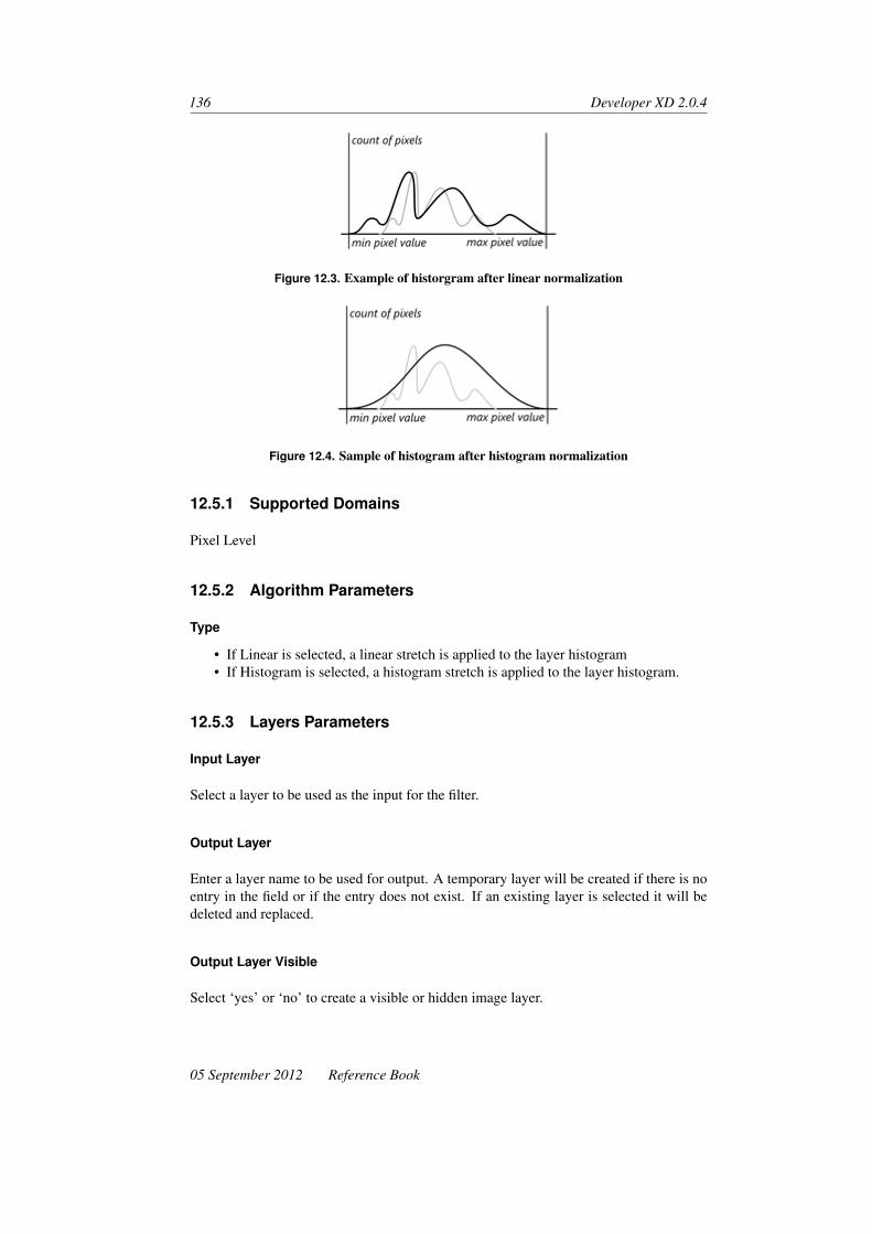
136 Developer XD 2.0.4
Figure 12.3. Example of historgram after linear normalization
Figure 12.4. Sample of histogram after histogram normalization
12.5.1 Supported Domains
Pixel Level
12.5.2 Algorithm Parameters
Type
• If Linear is selected, a linear stretch is applied to the layer histogram• If Histogram is selected, a histogram stretch is applied to the layer histogram.
12.5.3 Layers Parameters
Input Layer
Select a layer to be used as the input for the filter.
Output Layer
Enter a layer name to be used for output. A temporary layer will be created if there is noentry in the field or if the entry does not exist. If an existing layer is selected it will bedeleted and replaced.
Output Layer Visible
Select ‘yes’ or ‘no’ to create a visible or hidden image layer.
05 September 2012 Reference Book

Image Layer Operation Algorithms 137
Output Layer Type
Select the data type of the output layer. Available options are:
• As input layer• 8-bit unsigned• 16-bit unsigned• 16-bit signed• 32-bit unsigned• 32-bit signed• 32-bit float
12.6 Median Filter
Use the Median Filter algorithm to replace the pixel value with the median value ofneighboring pixels. The median filter may preserve image detail better than a mean filter.Both can be used to reduce noise.
12.6.1 Supported Domains
Pixel Level; Image Object Level; Current Image Object; Neighbor Image Object; SuperObjects; Sub Objects; Linked Objects
12.6.2 Kernel Parameters
2D Kernel Size
Enter a number to set the kernel size in one slice. The default value is 3.
Number of Slices
Enter the number of slices to be considered as part of the kernel. If a region is specifiedin the image object domain, the algorithm will use the region values in x slices above andx slices below ( x being the number of slices entered). If there is no region, the entire areaof the slices above and below will be considered part of the kernel. If there are insufficientslices or regions, only those available will be considered.
12.6.3 Layers Parameters
Input Layer
Select a layer to be used as the input for the filter.
Reference Book 05 September 2012

138 Developer XD 2.0.4
Input Region
Define a region within the input image layer. Select or enter the name of an existingregion. Alternatively, you can enter the co-ordinates of a region specified by its origin(xG,yG) , which is the lower left corner and its size [Rx,Ry,Rz,Rt ] . The input pattern is:(xG,yG,zG, tG) , [Rx,Ry,Rz,Rt ] . Alternatively, you can select a variable. To create a newvariable, type a name for the new variable and click OK or press Enter to open the CreateVariable dialog box for further settings.
Output Layer
Enter a name for the output layer or use the drop-down list to select a layer name to beused for output. If left empty, a temporary layer will be created. If a temporary layer isselected it will be deleted and replaced.
Output Layer Type
Select an output layer type from the drop-down list. Select As Input Layer to assign thetype of the input layer to the output layer.
12.7 Sobel Operation Filter
Creates a layer by applying Sobel operator.
12.7.1 Supported Domains
Pixel Level; Image Object Level; Current Image Object; Neighbor Image Object; SuperObjects; Sub Objects; Linked Objects
12.7.2 Kernel Parameters
2D Kernel Size
Enter a number to set the kernel size in one slice. The default value is 3.
Number of Slices
Enter the number of slices to be considered as part of the kernel. If a region is specifiedin the image object domain, the algorithm will use the region values in x slices above andx slices below ( x being the number of slices entered). If there is no region, the entire areaof the slices above and below will be considered part of the kernel. If there are insufficientslices or regions, only those available will be considered.
05 September 2012 Reference Book

Image Layer Operation Algorithms 139
12.7.3 Layers Parameters
Input Layer
Select a layer to be used as the input for the filter.
Input Region
Define a region within the input image layer. Select or enter the name of an existingregion. Alternatively, you can enter the co-ordinates of a region specified by its origin(xG,yG) , which is the lower left corner and its size [Rx,Ry,Rz,Rt ] . The input pattern is:(xG,yG,zG, tG) , [Rx,Ry,Rz,Rt ] . Alternatively, you can select a variable. To create a newvariable, type a name for the new variable and click OK or press Enter to open the CreateVariable dialog box for further settings.
Output Layer
Enter a layer name to be used for output. A temporary layer will be created if there is noentry in the field or if the entry does not exist. If an existing layer is selected it will bedeleted and replaced.
Output Layer Visible
Select ‘yes’ or ‘no’ to create a visible or hidden image layer.
Output Layer Type
Select the data type of the output layer. Available options are:
• As input layer• 8-bit unsigned• 16-bit unsigned• 16-bit signed• 32-bit unsigned• 32-bit signed• 32-bit float
12.8 Pixel Freq. Filter
The Pixel Frequency Filter algorithm scans the input layer and selects the color that isfound in the greatest number of pixels. The frequency is checked in the area defined bythe size of the kernel.
Reference Book 05 September 2012

140 Developer XD 2.0.4
12.8.1 Supported Domains
Pixel Level; Image Object Level; Current Image Object; Neighbor Image Object; SuperObject; Sub Objects; Linked Objects; Image Object List
12.8.2 Kernel Parameters
2D Kernel Size
Enter a number to set the kernel size. The default value is 3.
Number of Slices
Enter the number of slices to be considered as part of the kernel. If a region is specifiedin the image object domain, the algorithm will use the region values in x slices above andx slices below ( x being the number of slices entered). If there is no region, the entire areaof the slices above and below will be considered part of the kernel. If there are insufficientslices or regions, only those available will be considered.
12.8.3 Layers Parameters
Input Layer
Select a layer to be used as the input for the filter.
Input Region
Define a region within the input image layer. Select or enter the name of an existingregion. Alternatively, you can enter the co-ordinates of a region specified by its origin(xG,yG) , which is the lower left corner and its size [Rx,Ry,Rz,Rt ] . The input pattern is:(xG,yG,zG, tG) , [Rx,Ry,Rz,Rt ] . Alternatively, you can select a variable. To create a newvariable, type a name for the new variable and click OK or press Enter to open the CreateVariable dialog box for further settings.
Output Layer
Enter a layer name to be used for output. A temporary layer will be created if there is noentry in the field or if the entry does not exist. If an existing layer is selected it will bedeleted and replaced.
Output Layer Visible
Select ‘yes’ or ‘no’ to create a visible or hidden image layer.
05 September 2012 Reference Book

Image Layer Operation Algorithms 141
Output Layer Type
Select the data type of the output layer. Available options are:
• As input layer• 8-bit unsigned• 16-bit unsigned• 16-bit signed• 32-bit unsigned• 32-bit signed• 32-bit float
12.9 Pixel Min/Max Filter (Prototype)
Creates layer where each pixel has the difference of kernel max or min value to the centervalue.
12.9.1 Supported Domains
Pixel Level; Image Object Level; Current Image Object; Neighbor Image Object; SuperObject; Sub Objects; Linked Objects
12.9.2 Algorithm Parameters
Mode
Choose the min/max filter mode – diff. brightest to center, diff. center to darkest or diff.brightest to darkest.
12.9.3 Kernel Parameters
2D Kernel Size
Enter a number to set the kernel size in one slice. The default value is 3.
Number of Slices
Enter the number of slices to be considered as part of the kernel. If a region is specifiedin the image object domain, the algorithm will use the region values in x slices above andx slices below ( x being the number of slices entered). If there is no region, the entire areaof the slices above and below will be considered part of the kernel. If there are insufficientslices or regions, only those available will be considered.
Reference Book 05 September 2012

142 Developer XD 2.0.4
12.9.4 Layers Parameters
Input Layer
Select a layer to be used as the input for the filter.
Input Region
Define a region within the input image layer. Select or enter the name of an existingregion. Alternatively, you can enter the co-ordinates of a region specified by its origin(xG,yG) , which is the lower left corner and its size [Rx,Ry,Rz,Rt ] . The input pattern is:(xG,yG,zG, tG) , [Rx,Ry,Rz,Rt ] .
Alternatively, you can select a variable. To create a new variable, type a name for the newvariable and click OK or press Enter to open the Create Variable dialog box for furthersettings.
Output Layer
Enter a name for the output layer or use the drop-down list to select a layer name to beused for output. If left empty, a temporary layer will be created. If a temporary layer isselected it will be deleted and replaced.
Output Layer Visible
Select ‘yes’ or ‘no’ to create a visible or hidden image layer.
12.10 Edge Extraction Lee Sigma
The Edge Extraction Lee Sigma algorithm uses a specific edge filter that creates twoindividual layers from the original image. One layer represents bright edges, the otherone dark edges.
To extract two layers – one with bright and one with dark edges – this algorithm must beapplied twice with the appropriate settings changed. If two edge layers are created, it isimportant to give them two individual image layer aliases. Otherwise, the first existinglayer would be overwritten by the second generated layer.
12.10.1 Supported Domains
Pixel Level; Image Object Level; Current Image Object; Neighbor Image Object; SuperObjects; Sub Objects; Linked Objects
05 September 2012 Reference Book

Image Layer Operation Algorithms 143
12.10.2 Algorithm Parameters
Sigma
Set the Sigma value. The Sigma value describes how far away a data point is from itsmean, in standard deviations. A higher Sigma value results in a stronger edge detection;the default value is 5. The sigma value for a given window is:
∑ =
√σ2
(x)2
If the number of pixels P within the moving window that satisfy the criteria in the formulabelow is sufficiently large (where W is the width, a user-defined constant), the average ofthese pixels is output. Otherwise, the average of the entire window is produced.(
1−w∑
)PCenter ≤ P≤
(1+W ∑
)PCenter
Edge Extraction Mode
• If Dark is selected, edges of darker objects are extracted• If Bright is selected, edges of brighter objects are extracted
Input Layer
Use the drop-down list to select the input layer.
Input Region
Define a region within the input image layer. Select or enter the name of an existingregion. Alternatively, you can enter the co-ordinates of a region specified by its origin(xG,yG) , which is the lower left corner and its size [Rx,Ry,Rz,Rt ] . The input pattern is:(xG,yG,zG, tG) , [Rx,Ry,Rz,Rt ] .
Alternatively, you can select a variable. To create a new variable, type a name for the newvariable and click OK or press Enter to open the Create Variable dialog box for furthersettings.
Output Layer
Enter a name for the output layer or use the drop-down list to select a layer. If a temporarylayer is selected it will be deleted and replaced.
12.11 Edge Extraction Canny
Enhance or extract feature boundaries using Canny’s algorithm. Edge extraction filtersmay be used to enhance or extract feature boundaries. The resulting layer typically showshigh pixel values where there is a distinctive change of pixel values in the original imagelayer.
Reference Book 05 September 2012

144 Developer XD 2.0.4
12.11.1 Supported Domains
Pixel Level; Image Object Level; Current Image Object; Neighbor Image Object; SuperObjects; Sub Objects; Linked Objects
12.11.2 Algorithm Parameters
Algorithm
The Canny algorithm is provided.
Lower Threshold
Lower threshold is applied after higher threshold. During the first step, edges are detectedand pixels with values lower than Higher Threshold are removed from detected edges.During the final step, non-edge pixels (those previously removed because values wereless than higher threshold) with values higher than lower threshold are marked as edgenodes again. After applying the algorithm the first time, you can check results (edge pixelvalues) and the value for the threshold. Usually values for this field are from 0–5 – thedefault is 0.
Higher Threshold
After edges are detected, pixels with values lower than this threshold will not be markedas edge pixels. This allows removal of low intensity gradient edges from results. Afterapplying the algorithm once, users can check the results (values of edge pixels) and findthe correct value for the threshold. Usually values for this field are from 0–5 – the defaultis 0.
Gauss Convolution FWHM
Enter the width of the Gaussian filter in relation to full width at half maximum of theGaussian filter. This field determines the level of details covered by Gaussian filter. Ahigher value will produce a wider Gaussian filter and less detail will remain for edgedetection. Therefore, only high intensity gradient edges will be detected by Canny’salgorithm. The range of the field is 0.0001–15. The default value is 1.
Input Layer
Use the drop-down list to select a layer to use for input.
Input Region
Define a region within the input image layer. Select or enter the name of an existingregion. Alternatively, you can enter the co-ordinates of a region specified by its origin(xG,yG) , which is the lower left corner and its size [Rx,Ry,Rz,Rt ] . The input pattern is:
05 September 2012 Reference Book

Image Layer Operation Algorithms 145
(xG,yG,zG, tG) , [Rx,Ry,Rz,Rt ] . Alternatively, you can select a variable. To create a newvariable, type a name for the new variable and click OK or press Enter to open the CreateVariable dialog box for further settings.
Output Layer
Use the drop-down list to select a layer to use for output or enter a new name. Output is32-bit float. If the name of an existing 32-bit float temporary layer is entered or selected,it will be used. If a temporary layer is selected it will be deleted and replaced.
Sample Results The table below shows results of typical settings:
Original Layer Lower Threshold: 0
Higher Threshold: 0Gauss ConvolutionFWHM: 0.2
Lower Threshold: 0.3
Higher Threshold: 0.6Gauss ConvolutionFWHM: 0.2
Lower Threshold: 0.3
Higher Threshold:0.69Gauss ConvolutionFWHM: 0.2
12.12 Edge 3D Filter
The Edge 3D Filter algorithm creates a layer with 3D edge information.
12.12.1 Supported Domains
Pixel Level; Image Object Level; Current Image Object; Neighbor Image Object; SuperObject; Sub Object; Linked Objects
12.12.2 Algorithm Parameters
Smoothing Scale Factor
This parameter defines the sharpness of the detected edges. The value range is 0–1 –the larger the value, the more sharp an edge is displayed in the resulting image. Smallervalues will progressively blur the detected edges until they are unrecognizable.
Reference Book 05 September 2012

146 Developer XD 2.0.4
Return Option
• Edge 3D returns all edge signals• Mean + Edge 3D displays bright edges only (mean plus pixel value)• Mean - Edge 3D displays bright edges only (mean minus pixel value)
Edge Finding Method
• Abs. Deviation takes all pixels in the kernel• Abs. Deviation of Pixels Along Color Edges only considers pixels on edges
12.12.3 Kernel Parameters
2D Kernel Size
Enter a number to set the kernel size in one slice. The default value is 3.
Number of Slices
Enter the number of slices to be considered as part of the kernel. If a region is specifiedin the image object domain, the algorithm will use the region values in x slices above andx slices below ( x being the number of slices entered). If there is no region, the entire areaof the slices above and below will be considered part of the kernel. If there are insufficientslices or regions, only those available will be considered.
12.12.4 Layer Parameters
Input Layer
Select a layer to be used as the input for the filter.
Input Region
Define a region within the input image layer. Select or enter the name of an existingregion. Alternatively, you can enter the co-ordinates of a region specified by its origin(xG,yG), which is the lower left corner and its size [Rx,Ry,Rz,Rt ] . The input pattern is:(xG,yG,zG, tG), [Rx,Ry,Rz,Rt ] . Alternatively, you can select a variable. To create a newvariable, type a name for the new variable and click OK or press Enter to open the CreateVariable dialog box for further settings.
Output Layer
Enter a name for the output layer or use the drop-down list to select a layer name to beused for output. If left empty, a temporary layer will be created. If a temporary layer isselected it will be deleted and replaced.
05 September 2012 Reference Book

Image Layer Operation Algorithms 147
Output Layer Visible
Select ‘yes’ or ‘no’ to create a visible or hidden image layer.
12.13 Surface Calculation
Use the surface calculation algorithm to derive the slope for each pixel of a digital eleva-tion model (DEM). This can be used to determine whether an area within a landscape isflat or steep and is independent from the absolute height values. There is also an optionto calculate aspect using Horn’s method.
12.13.1 Supported Domains
Pixel Level; Image Object Level; Current Image Object; Neighbor Image Object; SuperObjects; Sub Objects; Linked Objects
12.13.2 Algorithm Parameters
Layer
Select the layer to which the filter will be applied. Gradient Unit and Unit of Pixelparameters apply to slope calculations only.
Algorithm
• Slope uses the Zevenbergen-Thorne method 1
• Aspect uses Horn’s method. 2
Gradient Unit
Available for slope. Select Percent or Degree from the drop-down list for the gradientunit.
Unit of Pixel Values
Enter the ratio of the pixel height to pixel size.
Input Layer
Use the drop-down list to select a layer for input.
1. Zevenbergen LW, Thorne CR (1987). Quantitative Analysis of Land Surface Topography. Earth SurfaceProcesses and Landforms, 12(1):47–56
2. Horn BKP (1981). Hill Shading and the Reflectance Map. Proceedings of the IEEE, 69(1):14–47
Reference Book 05 September 2012

148 Developer XD 2.0.4
Input Region
Define a region within the input image layer. Select or enter the name of an existingregion. Alternatively, you can enter the co-ordinates of a region specified by its origin(xG,yG) , which is the lower left corner and its size [Rx,Ry,Rz,Rt ] . The input pattern is:(xG,yG,zG, tG) , [Rx,Ry,Rz,Rt ] . Alternatively, you can select a variable. To create a newvariable, type a name for the new variable and click OK or press Enter to open the CreateVariable dialog box for further settings.
Output Layer
Enter a name for the output layer or use the drop-down list to select a layer name to beused for output. If left empty, a temporary layer will be created. If a temporary layer isselected it will be deleted and replaced.
Output Layer Type
Select an output layer type from the drop-down list. Select As Input Layer to assign thetype of the input layer to the output layer.
12.14 Layer Arithmetics
The layer arithmetic algorithm uses a pixel-based operation that enables the merger ofup to four layers by mathematical operations (+,−,×,÷). The layer created displaysthe result of this mathematical operation. This operation is performed on the pixel level,which means that all pixels of the image layers are used. For example, Layer 2 can besubtracted from Layer 1. This would mean that whenever the same pixel value in bothlayers exists, the result would be 0.
Before or after the operation, the layers can be normalized. Furthermore, weights can beused for each individual layer to influence the result.
12.14.1 Supported Domains
Pixel Level; Image Object Level; Current Image Object; Neighbor Image Object; SuperObjects; Sub Objects; Linked Objects
12.14.2 Algorithm Parameters
Input Layer
Select a layer to be used as the input for the filter.
05 September 2012 Reference Book
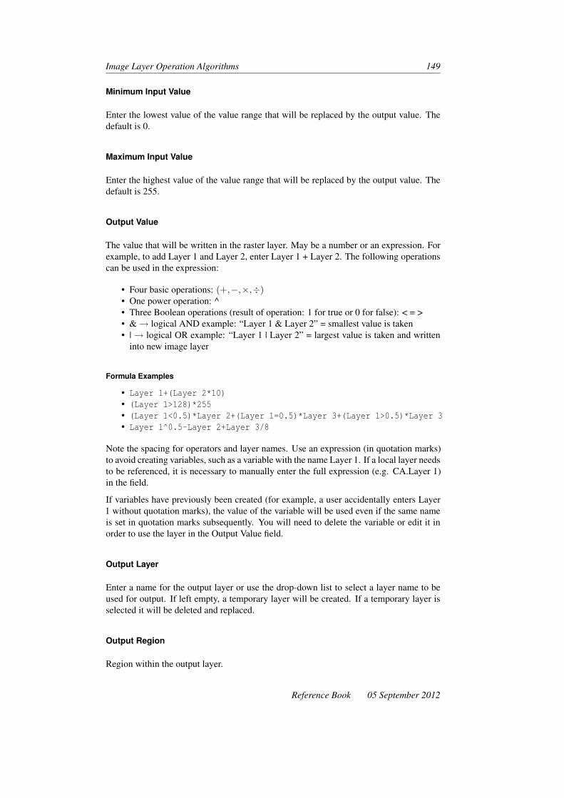
Image Layer Operation Algorithms 149
Minimum Input Value
Enter the lowest value of the value range that will be replaced by the output value. Thedefault is 0.
Maximum Input Value
Enter the highest value of the value range that will be replaced by the output value. Thedefault is 255.
Output Value
The value that will be written in the raster layer. May be a number or an expression. Forexample, to add Layer 1 and Layer 2, enter Layer 1 + Layer 2. The following operationscan be used in the expression:
• Four basic operations: (+,−,×,÷)• One power operation: ^• Three Boolean operations (result of operation: 1 for true or 0 for false): < = >• &→ logical AND example: “Layer 1 & Layer 2” = smallest value is taken• |→ logical OR example: “Layer 1 | Layer 2” = largest value is taken and written
into new image layer
Formula Examples
• Layer 1+(Layer 2*10)• (Layer 1>128)*255• (Layer 1<0.5)*Layer 2+(Layer 1=0.5)*Layer 3+(Layer 1>0.5)*Layer 3• Layer 1^0.5-Layer 2+Layer 3/8
Note the spacing for operators and layer names. Use an expression (in quotation marks)to avoid creating variables, such as a variable with the name Layer 1. If a local layer needsto be referenced, it is necessary to manually enter the full expression (e.g. CA.Layer 1)in the field.
If variables have previously been created (for example, a user accidentally enters Layer1 without quotation marks), the value of the variable will be used even if the same nameis set in quotation marks subsequently. You will need to delete the variable or edit it inorder to use the layer in the Output Value field.
Output Layer
Enter a name for the output layer or use the drop-down list to select a layer name to beused for output. If left empty, a temporary layer will be created. If a temporary layer isselected it will be deleted and replaced.
Output Region
Region within the output layer.
Reference Book 05 September 2012

150 Developer XD 2.0.4
Output Layer Visible
Select ‘yes’ or ‘no’ to create a visible or hidden image layer.
Output Layer Type
This field is available if the output layer does not yet exist. Select a data type for the rasterchannel if it must be created:
• 8-bit unsigned• 16-bit unsigned• 16-bit signed• 32-bit unsigned• 32-bit signed• 32-bit float
12.15 Line Extraction
The line extraction algorithm creates a layer and classifies the pixels of the input layeraccording to their line filter signal strength.
12.15.1 Supported Domains
Pixel Level
12.15.2 Algorithm Parameters
Line Direction
Enter the direction of the extracted line in degrees, between 0 and 179. The default valueis 0.
Line Length
Enter the length of the extracted line. The default value is 12.
Line Width
Enter the length of the extracted line. The default value is 4.
Border Width
Enter the width of the homogeneous border at the side of the extracted line. The defaultvalue is 4.
05 September 2012 Reference Book

Image Layer Operation Algorithms 151
Max Similarity of Line to Border
Enter a value to specify the similarity of lines to borders. The default value is 0.9.
Min Pixel Variance
Enter a value to specify the similarity of lines to borders. Use −1 to use the variance ofthe input layer. The default value is 0.
Min Mean Difference
Enter a value for the minimum mean difference of the line pixels to the border pixels. Ifpositive, bright lines are detected. Use 0 to detect bright and dark lines.
Input Layer
Use the drop-down list to select the layer where lines are to be extracted.
Output Layer
Enter or select a layer where the maximal line signal strength will be written. If a tempo-rary layer is selected it will be deleted and replaced.
Output Layer Visible
Select ‘yes’ or ‘no’ to create a visible or hidden image layer.
12.16 Pixel Filters Sliding Window
Creates a filtered image layer using various sliding window filter methods along orthogo-nal axes x,y or z .
12.16.1 Supported Domains
Pixel Level; Image Object Level; Current Image Object; Neighbor Image Object; SuperObjects; Sub Objects; Linked Objects
12.16.2 Algorithm Parameters
Algorithm
Choose the algorithm used in filtering.
Reference Book 05 September 2012
152 Developer XD 2.0.4
Input Image Layer
Select the image layer used for filtering. For some object-based filters, no input layer isneeded.
Filtered Layer
Float-valued image layer which stores the filter results.
12.16.3 Filter Kernel Sizes Selection Parameters
Kernel Size in x
Kernel size used for sliding window filter, which should always be an odd number. If thekernel size is 1, this filter axis is not used.
Kernel Size in y
Kernel size used for sliding window filter, which should always be an odd number. If thekernel size is 1, this filter axis is not used.
Kernel Size in z
Kernel size used for sliding window filter, which should always be an odd number. If thekernel size is 1, this filter axis is not used.
12.17 Abs. Mean Deviation Filter (Prototype)
The Abs. Mean Deviation Filter algorithm creates an image layer, where each pixel hasthe absolute deviation from mean with Gaussian weight.
12.17.1 Supported Domains
Pixel Level; Image Object Level; Current Image Object; Neighbor Image Object; SuperObject; Sub Objects; Linked Objects
12.17.2 Algorithm Parameters
Gauss Reduction
Reduction factor of standard deviation along the (unrotated) x axis
05 September 2012 Reference Book

Image Layer Operation Algorithms 153
Return Option
Select the filter response option:
• Circular• Elliptic:
– Gauss reduction ( y axis) is the reduction factor of the standard deviationalong the (unrotated) y axis
– Rotation angle ( xy axis) is the y axis rotation angle in the xy plane• Elliptic difference:
– Gauss reduction ( y axis) is the reduction factor of the standard deviationalong the (unrotated) y axis
– Rotation angle ( xy axis) is the y axis rotation angle in the xy plane
12.17.3 Kernel Parameters
2D Kernel Slice
Enter an odd number only for the filter kernel size. The default value is 3.
Number of Slices
Enter the number of slices to be considered as part of the kernel. If a region is specifiedin the image object domain, the algorithm will use the region values in x slices above andx slices below ( x being the number of slices entered). If there is no region, the entire areaof the slices above and below will be considered part of the kernel. If there are insufficientslices or regions, only those available will be considered.
12.17.4 Layers Parameters
Input Layer
Select a layer to be used as the input for the filter.
Input Region
Define a region within the input image layer. Select or enter the name of an existingregion. Alternatively, you can enter the co-ordinates of a region specified by its origin(xG,yG), which is the lower left corner and its size [Rx,Ry,Rz,Rt ]. The input pattern is:(xG,yG,zG, tG), [Rx,Ry,Rz,Rt ]. Alternatively, you can select a variable. To create a newvariable, type a name for the new variable and click OK or press Enter to open the CreateVariable dialog box for further settings.
Reference Book 05 September 2012

154 Developer XD 2.0.4
Output Layer
Enter a layer name to be used for output. A temporary layer will be created if there is noentry in the field or if the entry does not exist. If an existing layer is selected it will bedeleted and replaced.
Output Layer Visible
Select ‘yes’ or ‘no’ to create a visible or hidden image layer.
Output Layer Type
Select the data type of the output layer. Available options are:
• As input layer• 8-bit unsigned• 16-bit unsigned• 16-bit signed• 32-bit unsigned• 32-bit signed• 32-bit float
12.18 Contrast Filter (Prototype)
12.18.1 Supported Domains
Pixel Level
12.18.2 Algorithm Parameters
Input Layer
Input Layer
Temp Channel Alias
Name of generated temporary channel.
Calc Mode
Calculation Mode.
Channels Are Temp
New channels may be temporary or added to the project.
05 September 2012 Reference Book

Image Layer Operation Algorithms 155
12.19 Fill Pixel Values
The Fill Pixel Values algorithm lets you fill in raster regions based on the image objectdomain, by interpolation from neighbor object pixels. It is generally suitable for interpo-lating non-data areas in continuously varying rasters (such as elevation models).
To use this function, it is necessary to create and classify objects that define the pixels tobe interpolated (such as those with a zero value). This function works only on temporaryimage layers – these can be created or copied using the Layer Arithmetics on page 148algorithm).
12.19.1 Supported Domains
Image Object Level; Current Image Object; Neighbor Image Object; Super Objects; SubObjects; Linked Objects
12.19.2 Algorithm Parameters
Input Layer
Select the temporary image layer to be modified.
Class Filter
Object classes with known pixel values.
Calculation Mode
The following modes are available:
• Inverse Distance Weighting• Bi-linear Interpolation (a legacy function)
IDW Distance Weight A general form of finding an interpolated value u at a given pointx based on samples ui = u(xi) for i = 0,1, ...,N using IDW is an interpolating function:
φ(x,u) =(
∑Ni=0
(u−ui)2
d(x,xi)p
) 1p
derived from the minimizing condition∂φ(x,u)
∂u = 0
x denotes an interpolated (arbitrary) point, xi is an interpolating (known) point, d is agiven distance metric operator) from the known point xi to the unknown point x . N is thetotal number of known points used in interpolation and p is a positive real number, calledthe power parameter.
Reference Book 05 September 2012

156 Developer XD 2.0.4
IDW Distance Weight
This value corresponds to the exponent p in the formula for IDW distance weight.
05 September 2012 Reference Book

13 Thematic Layer OperationAlgorithms
Thematic layer operation algorithms are used to transfer data from thematic layers toimage objects and vice-versa.
13.1 Assign Class by Thematic Layer
Assign the classes stored in a thematic layer to image objects. This algorithm quicklyassigns all classes in thematic layers to an image object level. If an image object con-tains pixels with different classification within the thematic layer, the classification of themajority of the pixels is assigned to the image object.
Classes are matched by name between the thematic layer and the class hierarchy. Thealgorithm assumes that classes with the same names must be present in the class hierarchy.The class mode parameter sets the behavior if no matching class can be found.
13.1.1 Supported Domains
Image Object Level; Image Object List
13.1.2 Algorithm Parameters
Thematic Layer
Specify the thematic layer where classification values will be read.
Thematic Layer Attribute
Specify the thematic layer attribute column that contains classification values.
Class Mode
Specify the behavior when the class specified in the thematic layer is not present in therule set.
157

158 Developer XD 2.0.4
• Skip if class does not exist – class assignment is skipped if the class specified inthe thematic layer is not present in the rule set
• Use default class – use a default class if the class specified in the thematic layer isnot present in the rule set
• Create new class – a random, unique color will be assigned to the new class in theClass Hierarchy window.
Default Class
Only available if class mode is Use Default Class. Specify the default class for this mode.
13.2 Synchronize Image Object Hierarchy
Change an image object level to exactly represent the thematic layer. Image objectssmaller than the overlapping thematic object will be merged; image objects intersectingwith several thematic objects will be cut.
13.2.1 Supported Domains
Image Object Level; Image Object List
13.2.2 Algorithm Parameters
Thematic Layer
Select a thematic layer to be represented.
13.3 Read Thematic Attribute
Create and assign local image object variables according to a thematic layer attributetable. A variable with the same name as the thematic attribute will be created, attachedto each image object in the domain and filled with the value given by the attribute table.
13.3.1 Supported Domains
Image Object Level; Image Object List
13.3.2 Algorithm Parameters
Thematic Layer
Select the thematic layer for the algorithm.
05 September 2012 Reference Book
Thematic Layer Operation Algorithms 159
Thematic Layer Attribute
Choose attributes from the thematic layer for the algorithm. You can select any numericattribute from the attribute table of the selected thematic layer.
Variable
Select an existing variable or enter a new name to add a new one. If you have not alreadycreated a variable, the Create Variable dialog box will open.
13.4 Write Thematic Attributes
Generate a attribute column entry from an image object feature. The updated attributetable can be saved to a .shp file.
13.4.1 Supported Domains
Image Object Level
13.4.2 Algorithm Parameters
Thematic Layer
Select the thematic layers for the algorithm.
Feature
Select the feature for the algorithm.
Save Changes to File
If the thematic layer is linked with a shapefile, the changes can be updated to the file.
Reference Book 05 September 2012


14 Workspace AutomationAlgorithms
Workspace automation algorithms are used for working with subroutines of rule sets.These algorithms enable you to automate and accelerate the processing of workspaceswith particularly large images. Using workspace automation algorithms you can createmulti-scale workflows, which integrate analysis of images at different scales, magnifica-tions, or resolutions.
14.1 Create Scene Copy
Create a scene copy that is a duplicate of a project with image layers and thematic lay-ers, but without any results such as image objects, classes, or variables. This algorithmenables you to use subroutines.
14.1.1 Supported Domains
Execute; Maps
14.1.2 Algorithm Parameters
Scene Name
Edit the name of the scene copy to be created.
Scale
See Scale (p 124) for an explanation of the Select Scale dialog box.
Additional Thematic Layers
Edit the thematic layers you wish to load to a scene copy. This option is used to loadintermediate result information that has been generated within a previous subroutine andexported to a geocoded thematic layer. Use semicolons to separate multiple thematiclayers, for example, ThematicLayer1.tif;ThematicLayer2.tif.
161

162 Developer XD 2.0.4
14.2 Create Scene Subset
Copy a portion (subset) of a scene as a project with a subset of image layers and thematiclayers. Image objects, classes and variables are not copied. The algorithm uses the givenco-ordinates (geocoding or pixel co-ordinates) of the source scene. You can create subsetcopies of an existing subset.
14.2.1 Supported Domains
Execute; Image Object Level
14.2.2 Algorithm Parameters
Scene Name
Edit the name of the scene copy to be created.
Use Variable as Scale
Specify the scale for copying a map using a variable, rather than defining a numericalvalue.
Scale
See Scale (p 124) for an explanation of the Select Scale dialog box.
Border Size
Extends the bounding box of the image object by the entered border size in pixels. (Onlyavailable when image object level is selected as the image object domain.)
Include Maps With Objects Linked Via
Class filter for object link class that links objects on different maps. the subset willcontain all maps where the current object has linked objects on. (Only available whenimage object level is selected as the image object domain.)
Exclude Other Image Objects
Define a no-data area outside of the current image object to exclude other image objectsfrom further processing. (Only available when image object level is selected as the imageobject domain.) Selecting ‘yes’ brings up two further parameters:
• Customize Path – if set to ‘yes’, the Export Path parameter is activated
05 September 2012 Reference Book

Workspace Automation Algorithms 163
• In Export Path, enter the file attributes and filepath in the form{:Workspc.Output.Root}\:Scene.Name}_{:Variable:MyVariable}.ext orsimply C:\MyFile.tif
Desktop Export Folder
Specify the file export folder used for desktop processing. If the algorithm is run indesktop mode, files will be stored at this location. In server processing mode, the filelocation is defined in the export settings specified in the workspace.
Minimum and Maximum X, Y, Z & T Co-ordinates
Edit the co-ordinates of the subset. For the default co-ordinates orientation (0,0) in thebottom left-hand corner, the different co-ordinates are defined as follows:
Figure 14.1. Co-ordinates of a subset
• The minimum X co-ordinates describe the left border• The maximum X co-ordinates describe the right border• The minimum Y co-ordinates describe the lower border• The maximum Y co-ordinates describe the upper border.
Alternatively, click the drop-down arrow button to select available variables. Entering aletter will open the Create Variable dialog box.
Co-ordinates Orientation
You can change the corner of the subset that is used as the calculation base for the co-ordinates. The default is (0,0) in the lower-left corner.
Additional Thematic Layers
Edit the thematic layers you wish to load to a scene copy. This option is used to loadintermediate result information that has been generated within a previous subroutine andexported to a geocoded thematic layer. Use semicolons to separate multiple thematiclayers, for example, ThematicLayer1.tif;ThematicLayer2.tif.
Reference Book 05 September 2012

164 Developer XD 2.0.4
14.3 Create Scene Tiles
Create a tiled copy of a scene. Each tile is a separate project with its own image layersand thematic layers. Together the tile projects represent the complete scene as it wasbefore creating the tiled copy. The given co-ordinates (geocoding or pixel co-ordinates)of the source scene of the rule set are used. Results are not included before the tiles areprocessed.
After processing, you can stitch the tile results together and add them to the completescene within the dimensions as it was before creating the tiled copy. You can tile scenesand subsets several times.
14.3.1 Supported Domains
Execute
14.3.2 Tile Size Parameters
Tile Height
Edit the height of the tiles to be created. Minimum height is 100 pixels.
Tile Width
Edit the width of the tiles to be created. Minimum with is 100 pixels.
14.4 Submit Scenes for Analysis
This algorithm enables you to connect subroutines with any process of the main processtree or other subroutines. You also can also choose whether to stitch the results of theanalysis of subset copies.
A rule set that contains the submit scenes for analysis algorithm can only be executedif you are connected to Definiens Server. Rule sets that include subroutines cannot beprocessed on a local machine.
14.4.1 Supported Domains
Execute
14.4.2 Algorithm Parameters
Type of Scenes
Select the type of scene to submit to analysis – the top level scenes, tiles, or subsets andcopies.
05 September 2012 Reference Book

Workspace Automation Algorithms 165
If you select top-level scenes, they can only be submitted on the client, and not on a server.This option is designed for use with actions that are used in the Analysis Builder windowand that will not be analyzed on the server.
State Filter
This field only displays for top-level scenes. The default is any state. use the drop-downlist to select a processing state: created, edited, processed, failed, canceled or rejected.
Submit Recursively
Submits scenes recursively.
Scene Name Prefix
Enter the prefix of the names of scene copies to be selected for submitting. A prefix isdefined as the complete scene name or the beginning of it. Enter the unique part of thename to select only that scene, or the beginning of the name to select a group with similaror sequential names. For example, if you have scene names 7a, 7b and 7c, you can selectthem all by entering a 7, or select one by entering 7a, 7b or 7c.
Process Name
Address a subroutine or a process in the process tree of a subroutine for execution byusing a forward slash before hierarchy steps, for example, subroutine/process name. Youcan use the context menu in the Process Tree window to copy a process and paste it intothis field.
Parameter Set for Process
Select a parameter set to transfer variables to the following subroutines. Click the ellipsisbutton to open the Select Parameter Set dialog box.
Percent of Tiles to Submit
If you do not want to submit all tiles for processing but only a certain percentage, youcan edit the percentage of tiles to be processed. If you change the default value of 100,the tiles are selected randomly. If the calculated number of tiles to be submitted is not aninteger it is rounded up to the next integer.
If the value entered is less than or equal to 0, 1.0 will be used. If the value entered isgreater than 100, 100 will be used. Tiles that are not selected are automatically assignedthe status “skipped”.
Reference Book 05 September 2012

166 Developer XD 2.0.4
14.4.3 Stitching Parameters
Stitch Subscenes
Select Yes to stitch the results of subscenes together and add them to the complete scenewithin its original dimensions. Only the main map of a tile projects can be stitched.
Overlap Handling
If Subsets and Copies are stitched, the overlapping must be managed. You can opt tocreate Intersection image objects (default) or select Union to merge the overlapping imageobjects.
Class for Overlap Conflict
Overlapping image objects may have different classifications. In that case, you can definea class to be assigned to the image objects resulting from overlap handling.
14.4.4 Post-Processing Parameters
Request Post-Processing
Select Yes to execute another process after subscenes are processed.
Post-Process Name
Address a subroutine or a process in the process tree of a subroutine for execution byusing a forward slash before hierarchy steps, for example, subroutine/process name. Youcan use the context menu in the Process Tree window to copy a process and paste it intothis field.
Parameter Set for Post-Process
Select a parameter set to transfer variables to the following subroutines. Click the ellipsisbutton to open the Select Parameter Set dialog box.
14.5 Delete Scenes
Delete the scenes you no longer want to use or store.
14.5.1 Supported Domains
Execute
05 September 2012 Reference Book

Workspace Automation Algorithms 167
14.5.2 Algorithm Parameters
Type of Subscenes
Select the type of scene copy to be deleted: tiles or subsets and copies.
Scene Name Prefix
Enter the prefix of the names of scene copies to be selected for deleting. A prefix isdefined as the complete scene name or the beginning of it. Enter the unique part of thename to select only that scene, or the beginning of the name to select a group with similaror sequential names. For example, if you have scene names 7a, 7b and 7c, you can selectthem all by entering a 7, or select one by entering 7a, 7b or 7c.
Delete Results
If No is selected, the subset or tile is removed from the Workspace, along with the .dprfile and the shapefile. If Yes is selected (the default), all exported results will additionallybe deleted.
2.0.3 Compatibility Mode
Selecting Yes activates backward compatibility for Developer XD 2.0.3
14.6 Read Subscene Statistics
Read exported result statistics and perform a defined mathematical summary operation.The resulting value is stored as a variable that can be used for further calculations orexport operations concerning the main scene. This algorithm summarizes all values inthe selected column of a selected export item, using the selected summary type.
When the analysis of subscenes results in exporting statistics for each scene, the algorithmallows you to collect and merge the statistical results of multiple files. The advantage isthat you do not need to stitch the subscenes results for result operations concerning themain scene. The following preconditions apply:
• For each subscene analysis, a project or domain statistic has already been exported• All preceding subscene analysis including export has been processed completely
before the read subscene statistics algorithm starts any result summary calculations.To ensure this, result calculations are done within a separate subroutine.
14.6.1 Supported Domains
Execute
Reference Book 05 September 2012

168 Developer XD 2.0.4
14.6.2 Algorithm Parameters
Use Variable as Scene Type
This function lets you use the text of a variable containing a scene type, rather than thescene type itself. Selecting ‘yes’ activates the Scene Type Variable parameter.
Scene Type Variable
Create or select a scene type variable.
Type of Scene
Select the type of scene to be submitted (this parameter only appears if Use Variable asScene Type is set to ‘no’):
• Current scene• Subsets and copies• Subset and copies recursively• Tiles• Tiles recursively• Tiles from subset.
Scene Name Prefix
Enter the prefix of the names of the scenes to be selected for reading. A prefix is definedas the complete or the beginning of the scene name. Enter the unique part of the nameto select only that scene, or the beginning of the name to select a group with similar orsequential names. For example, if you have scene names 7a, 7b and 7c, you can selectthem all by entering a 7, or select one individually by entering 7a, 7b or 7c.
Export Item
Enter the name of the export item statistics to be summarized (for exampleProjectStatistics or ObjectStatistics).
Output Type
This value specifies the type of statistical output:
• Single Column reads single column values and writes output to the specified vari-able
• All Columns reads all available columns, creates a variable for each one, then putsthese variables into a specified feature list
05 September 2012 Reference Book

Workspace Automation Algorithms 169
Column
If ‘single column’ is selected as the Output Type, specify which column should be usedby the algorithm for the statistical summary operation.
Feature List
The Feature List parameter appears when ‘all columns’ is selected as the output type.Enter the feature list variable to receive the columns.
Add Summary Prefix
The Add Summary Prefix option appears when the Output Type parameter is set to ‘allcolumns’. It adds the summary type as a prefix to each variable’s name.
14.6.3 Mathematical Parameters
The following summary operations are available:
Value Description
Count Calculate the number of items
Sum Sum all values of appropriate statistics table columns
Mean Calculate the average of all values
Std. Dev. Calculate the standard deviation of all values
Min Calculate the minimal value of all values
Max Calculate the maximal value of all values
The following parameters are common to all the mathematical parameters:
Use Variable for Usage Flag
If ‘yes’ is selected, a variable value is used to calculate a summary; if set to ‘no’, a fixedvalue is used
Calculate Summary
Select ‘yes’ to calculate the summary.
Result Variable
Enter a variable to store the resulting value. (This parameter is only visible if SingleColumn is selected and Calculate Summary is set to ‘yes’.)
Reference Book 05 September 2012


15 Interactive OperationAlgorithms
Interactive operation algorithms are used to provide user interaction with the user ofactions in Architect XD.
15.1 Show User Warning
Edit and display a user warning.
15.1.1 Supported Domains
Execute
15.1.2 Algorithm Parameters
Message
Edit the text of the user warning.
15.2 Delete a File
Delete any file or folder in a Workspace directory.
15.2.1 Supported Domains
Execute
15.2.2 Algorithm Parameters
File Name
Define the filename and the path of the parameter set files to be loaded.
171

172 Developer XD 2.0.4
You can use the suggested file name pattern {:Workspc.OutputRoot\}parameter_sets\paramset.psf. It defines the folder parameter_sets locatedin the workspace output root folder as displayed in the Workspace Properties dialogbox. The parameter set files are named paramset, followed by the filename ending asdescribed below and the file extension .psf.
Click the drop-down arrow to select text elements for editing the filename pattern.
File Name Ending
Define the filename ending to add to the File Name field. Click the drop-down arrowto select an available variable. Alternatively, you can insert text between the quotationmarks.
15.3 Set Active Pixel
Sets the active pixel to the given co-ordinate.
15.3.1 Supported Domains
Execute
15.3.2 Algorithm Parameters
X Co-ordinate/Y Co-ordinate
There are two ways to set the value:
1. Assign the value by entering a numeric value, or enter a non-numeric value tocreate a variable
2. Click the drop-down list to select a feature.
15.4 Create/Modify Project
Create a new project or modify an existing one.
15.4.1 Supported Domains
Execute
05 September 2012 Reference Book

Interactive Operation Algorithms 173
15.4.2 Image Layer Parameters
Image File
Browse for an image file containing the image layers. Alternatively you can edit the path.
Image Layer ID
Change the image layer ID within the file. Note, that the ID is zero-based.
Image Layer Alias
Edit the image layer alias.
15.4.3 Thematic Layer Parameters
Thematic File
Browse for a thematic file containing the thematic layers. Alternatively, you can edit thepath.
Attribute Table File
Browse for an attribute file containing thematic layer attributes. Alternatively, you canedit the path.
Attribute ID Column Name
Edit the name of the column of the attribute table containing the thematic layer attributesof interest.
Thematic Layer Alias
Edit the thematic layer analysis.
15.4.4 General Settings Parameters
Show Subset Selection
Opens the Subset Selection dialog box when executed interactively.
Enable Geocoding
Activate to select the bounding co-ordinates based on the respective geographical co-ordinate system.
Reference Book 05 September 2012
174 Developer XD 2.0.4
15.5 Manual Classification
This algorithm allows the user of an action to classify image objects of the selected classmanually by clicking on them.
15.5.1 Supported Domains
Execute
15.5.2 Algorithm Parameters
Class
Select a class that can be assigned manually.
Use Brush
The Use Brush parameter, when assigned the value Yes, activates a brush tool. Holdingdown the left mouse button allows a user to manually classify objects by dragging themouse over them. If this action is performed while pressing the Shift key, objects areunclassified.
Brush Size
Define the brush size used for classification.
15.6 Configure Object Table
Display a list of all image objects together with selected feature values in the ImageObject Table window.
15.6.1 Supported Domains
Execute
15.6.2 Algorithm Parameters
Classes
Select classes to list all of its image objects.
05 September 2012 Reference Book

Interactive Operation Algorithms 175
Features
Select the features to display the feature values of the image objects.
15.7 Select Input Mode
Set the mode for user input via graphical user interface.
15.7.1 Supported Domains
Execute
15.7.2 Algorithm Parameters
Input Mode
Select an input mode:
• If Normal is selected, normal input mode is returned to (for example, selection ofimage objects by clicking them)
• Manual Object Cut activates the Cut Objects Manually function.
15.8 Start Thematic Edit Mode
The Start Thematic Edit Mode algorithm activates thematic editing, creation of thematiclayers and drawing functions. This mode can call on any map, not just the active one.The following actions are available after execution:
• Click and hold the left mouse button as you drag the cursor across the image tocreate a path with points in the image
• To create points at closer intervals, drag the cursor more slowly or hold the Ctrl keywhile dragging.
• Release the mouse button to automatically close the polygon• Click along a path in the image to create points at each click. To close the polygon,
double-click or select Close Polygon in the context menu• To delete the last point before the polygon is complete, select Delete Last Point in
the context menu.
15.8.1 Supported Domains
Execute
Reference Book 05 September 2012

176 Developer XD 2.0.4
15.8.2 Algorithm Parameters
Mode
Select Full Editing or Classify Only. The Classify Only option enables the editing ofclass and layer name parameters only.
Class
Selct an annotation class.
Use Magnetic Snap
When this function is activated and the user draws a line around an image object with themouse, the line will automatically snap to the area of highest contrast.
Magnetic Snap Radius
Insert a value to specify a detection radius; the magnetic snap detects edges only withinthe specified distance. A value of zero means no magnetic snap.
Thematic Layer Name
The thematic layer name for manual annotation.
15.9 Select Thematic Objects
Use the Select Thematic Objects algorithm to enable selection of thematic objects inthe user interface. The algorithm activates thematic editing and enables cursor selectionmode. It is designed to be used with actions.
15.9.1 Algorithm Parameters
Layer Name
Enter the name of the layer where thematic objects are to be selected.
Selection Mode
Choose the type of selection:
• Single: enables selection of single polygons.• Polygon: enables selection of all shapes within a user-drawn polygon.• Line: enables selection of all shapes crossed by a user-drawn line.• Rectangle: enables selection of all shapes within a user-drawn rectangle.
05 September 2012 Reference Book
Interactive Operation Algorithms 177
15.10 Finish Thematic Edit Mode
Use the Finish Thematic Edit Mode algorithm to switch back from thematic editing toimage object editing and save the shapefile. It is designed to be used with actions and canbe used on multi-scene projects.
15.10.1 Supported Domains
Execute
15.10.2 Algorithm Parameters
Save Changes
Selct Yes to save manual editing changes into the file.
File Name
Define the file name of the shapes file.
15.11 Select Image Object
Select an image object designated in the image object domain in the active view. The pro-cess has the same effect as if the user manually selects the image object with the mouse.You can use this algorithm in Architect solutions if you want to highlight an image objector automatically display its properties in the Image Object Information window. Only thefirst image object in the selected domain will be selected.
15.11.1 Supported Domains
Image Object Level; Current Image Object; Super Object; Sub Objects; Linked Objects
15.11.2 Algorithm Parameters
None
15.12 Polygon Cut
The Polygon Cut algorithm allows users to manually cut image objects. When activated,the client will enter polygon input mode, which allows line or polygon editing as specifiedby the rule set writer. Line and polygon mode are identical except in polygon mode, theuser can close a shape by double-clicking or releasing the mouse button near the start
Reference Book 05 September 2012

178 Developer XD 2.0.4
point. New objects can be classified according to classification parameters and there isan option to store them in an object list variable.
When creating a polygon, displaying the context menu by right-clicking offers the follow-ing options for a open polygon:
• Cancel Split deletes the entire polygon• Close and Split joins the first and last points together• Delete Last Point removes the last point created
The following restrictions apply:
• In polygon mode, if the area of the bounding box exceeds 2,048 x 2,048, a warningwill appear that the process will take some time to excecute and prompts users ifthey want to continue
• In polygon mode, if the area of the bounding box exceeds 10,000 x 10,000, awarning is shown that this value cannot be exceeded and the cutting action is notexecuted
• In 3D and 4D projects, the cutting is always performed within a single xy slice at asingle time point.
15.12.1 Supported Domain
Execute
15.12.2 Algorithm Parameters
Mode
• Polygon Cut – in polygon mode, a closed polygon is drawn and the area inside it iscut
• Line Cut – in line mode, a line is drawn and rasterized by creating pixel widthimage objects along the line
Class
Specify the class of objects to be annotated.
Use Magnetic Snap
Select ‘yes’ or ‘no’. If ‘yes’ is selected, the drawn line will automatically snap to high-contrast areas, when the user drags the mouse while holding down the left mouse button
Magnetic Snap Radius
Insert a value to specify a detection radius; the magnetic snap detects edges only withinthe specified distance. A value of zero means no magnetic snap. The default value is 30.
05 September 2012 Reference Book

Interactive Operation Algorithms 179
Class Filter
Specify the class of objects to be cut.
Image Object List
If selected, the image object list variable that will receive the cut image objects.
Callback Process
The path to the process invoked after each cut operation.
Preserve Object Type for Cut Objects
Select ‘yes’ or ‘no’. If ‘yes’ is selected, the image object type will be preserved for cutimage objects. If ‘no’ is chosen, cut image objects will be marked as disconnected (thisoption is less processor intensive).
Ensure Connected for Objects Created by the Cut
Select ‘yes’ or ‘no’. If ‘yes’ is selected, the resulting image objects will be converted toconnected 2D. If ‘no’ is chosen, resulting image objects will be marked as disconnected.
15.13 Save/Restore View Settings
Save and restore view settings of the active view. Use this algorithm to configure thecurrent view to a predefined setting used in Architect XD solutions. This is achieved intwo steps: first the current view settings are stored using the Save View Settings mode.Then the active view can be restored to the saved view settings by invoking it in theRestore View Settings mode.
15.13.1 Supported Domain
Execute
15.13.2 Algorithm Parameters
Mode
• Save view settings – in this mode the view settings can be saved. They will bestored together with the algorithm. Use the View Settings parameter to save thecurrent view.
• Restore view settings – in this mode the view settings are restored to the staterepresented by another process using this algorithm in the Save View Settings mode.Use the Process Path parameter to specify the process that stores the view settings.
Reference Book 05 September 2012

180 Developer XD 2.0.4
View Settings
This parameter is only available in the Save View Settings mode. Click the ellipsis in theValue column (which displays Click to Capture View Settings) to store the current viewsettings. In addition to main maps, the view settings for maps and window splits are alsosaved.
Process Path
This parameter is only available in the Restore View Settings mode. Refer to anotherprocess using this algorithm in Save View Settings mode to restore the view settings thatare stored in this algorithm. To refer to a process, right-click on it and select Go To toopen the Go To Process dialog box.
15.14 Display Map
This algorithm displays a specific map in the currently active view. It can be used toconfigure the correct view for the user in interactive Architect solutions that use multiplemaps.
15.14.1 Supported Domains
Execute
15.14.2 Algorithm Parameters
Map Name
Select the name of the map to display in the current active view.
15.15 Define View Layout
In Architect XD you can define a particular window layout for end users. The DefineView Layout algorithm allows you to display windows split into one, two or four with adifferent map displayed in each pane or a 3D projection.
The following view properties apply:
• If a map is not available, the main map is displayed• When changing layouts using the same map, the zoom properties of the active
window are used• When changing maps, the image is adjusted to the size of the window• Any layout settings, such as numbers of layers or outlines, are reset when changing
layouts.
05 September 2012 Reference Book

Interactive Operation Algorithms 181
15.15.1 Supported Domains
Execute
15.15.2 Algorithm Parameters
Split Type
• No Split• Split Vertically• Split Horizontally• 4 Panes• Comparison View for a 2D project, two vertical panes; for a 3D project, compar-
isons of XY, XZ or YZ views
View Type
• Independent View• Side by Side View• Swipe View
Synchronize Views
Define how image views are laid out and what content is displayed, for each image view.Select yes to synchronize all the map views with each other.
15.15.3 Pane Parameters
Map Name
Select the name of the map to display in the current active view.
Projection
XY, XZ, YZ or 3D
15.16 Set Custom View Settings
Apply custom view settings to the active view.
15.16.1 Supported Domains
Execute
Reference Book 05 September 2012

182 Developer XD 2.0.4
15.16.2 Algorithm Parameters
Classification
Select which classification display settings should be applied. Values are On or Off.
Outlines
Select which outline display settings should be applied; available values are None,Opaque and Transparent.
Thematic Objects
Display vector layer polygons in image view, without entering particular editing mode.Values are On or Off.
15.17 Change Visible Layers
Many algorithms use temporary layers for computation purposes; however, this may beconfusing for people who are running solutions in Architect XD and Tissue Studio™.The Change Visible Layers algorithm allows rule-set developers to specify the visibilityof new image layers. Hidden layers are hidden by default in Definiens Developer XD2.0.4, although it is possible to turn this option on and off in Tools > Options (for moredetails consult the user guide).
15.17.1 Supported Domains
Execute
15.17.2 Algorithm Parameters
Apply to
Select whether to apply the action to image layers or thematic layers.
Mode
The following options are available:
• Show single layer• Hide single layer• Show all layers• Hide all layers
05 September 2012 Reference Book

Interactive Operation Algorithms 183
Image Layer/Thematic Layer
Select the image layer or thematic layer (depending on your selection in the Apply Tofield) to show or hide.
15.18 Change Visible Map
The Change Visible Map algorithm lets you show or hide maps in image view. You candefine which maps can be displayed.
15.18.1 Supported Domains
Execute
15.18.2 Algorithm Parameters
Show Map
Choose from the following values:
• Main• From Parent• Active Map• <Create New Variable>
Hide Map
Values for the Hide Map parameter are the same as those for Show Map.
Allow Empty Image View
When Allow Empty Image View has a value of “yes”:
• If Show Map has no value and a map is selected in the Hide Map field, this map isremoved and a black image view is displayed
• If a map is selected in the Show Map field but Hide Map has no value, all blackimage views will display the selected map
15.19 Show Scene
The Show Scene algorithm allows the user to navigate through the slide hierarchy. Thisfacility only functions in the context of workspaces.
Reference Book 05 September 2012

184 Developer XD 2.0.4
15.19.1 Algorithm Parameters
Show Scene
Select from the following:
• First child• First slide• Next sibling• Next slide• Previous sibling• Previous slide• Parent
15.20 Ask Question
15.20.1 Supported Domains
Execute
15.20.2 Algorithm Parameters
Message
Amend this value to change the title of the dialog box.
Result
Insert a value that will store the result. If the user selects ‘yes’, the value is 1; if ‘no’ isselected, the value is 0.
15.21 Set Project State
The standard configuration of Definiens Developer XD 2.0.4 is to prompt the user to savea project upon closing, even if the user has not made any changes to the file. The SetProject State algorithm allows rule-set writers to disable this prompt.
15.21.1 Supported Domains
Execute
05 September 2012 Reference Book

Interactive Operation Algorithms 185
15.21.2 Algorithm Parameters
Mark Project As
Set this value to modified or unmodified. If modified is selected, the user will be promptedto save; if unmodified is selected, this option will not appear.
15.22 Save/Restore Project State
This algorithm lets you save or restore the state of all maps, levels and image projects aspart of a rule set.
15.22.1 Supported Domains
Execute
15.22.2 Algorithm Parameters
Mode
Choose either ‘save state’ or ‘restore’:
• In save mode, the algorithm saves all maps to a temporary project file• in restore mode, the algorithm restores the previously saved state from the project
file.
Name of the State to be Saved or Restored
Enter a name in quotes, or use the drop-down list to select a variable, feature or arrayitem.
15.23 Show HTML Help
The Show HTML Help algorithm allows developers to incorporate an HTML file into arule set. This can be displayed as a pop-up window that launches in response to a useraction. This is useful for adding additional help information to a function.
The help dialog contains a checkbox with the label ‘do not show again’, which disablesthe function for a period of two weeks.
15.23.1 Supported Domains
Execute
Reference Book 05 September 2012

186 Developer XD 2.0.4
15.23.2 Algorithm Parameters
Help File Name
Define the name of the help file. The HTML file must be created independently andconform to the defined address.
Shapes File
Enter the name of the shape file
15.24 Configure Manual Image Equalization
The Configure Manual Image Equalization algorithm sets the manual image layer equal-ization display for active or all image views.
15.24.1 Supported Domains
Execute
15.24.2 Algorithm Parameters
Apply to all Image Views
Select ‘yes’ to apply settings to all image views. If ‘no’ is selected, settings will beapplied to the active image view only.
Use Variable for Equalization
If ‘yes’ is selected, the software will expect a scene variable of the string type as anequalization parameter. If ‘no’ is selected, equalization must be specified explicitly.
Equalization
Select one of the following equalization modes:
• Linear• Linear – Inverse• Gamma Correction (Positive)• Gamma Correction (Negative)• Gamma Correction (Positive) – Inverse• Gamma Correction (Negative) – Inverse
05 September 2012 Reference Book

Interactive Operation Algorithms 187
Range Type
There are two ways to define the range – Min/Max or Center/Width. The value range willnot exceed the limitations of the channel; for example, the value for an 8-bit channel willalways be between 0 and 255.
min = center− width2
,max = center+width
2
Min/Max Specify the minimum and maximum value for the layer equalization range.
Center/Width Specify the center and width values for the layer equalization range.
Apply to all Visible Layers
Select ‘yes’ to apply manual equalization to all visible image layers.
Interactive Range Editing Step
The value of the Interactive Range Editing Step represents the step-size in pixels, for theinteractive mouse action.
15.25 Edit Aperio Annotation Links
This algorithm launches the Aperio annotation Link Manager dialog, where users candefine annotation mapping. Two options are available in the Link Manager:
• Link by name: Aperio annotations are linked by name (defined layer name) withDefiniens ROI.
• Link by position: Aperio annotations are linked by position (1st Aperio–last Aperiolayer position) with Definiens ROI.
Pressing OK executes the child process Apply Aperio Annotation Links.
This function requires a connection to a Aperio Spectrum database. For more informationon configuration options and the Link Manager, please consult the Aperio chapter of theTissue Studio User Guide.
15.25.1 Supported Domains
Execute
15.25.2 General Parameters
Threshold Condition
Define an additional threshold condition to define the candidate image object domain.
Reference Book 05 September 2012

188 Developer XD 2.0.4
Map
Choose one of the following values:
• Main• From Parent• Active Map• <Create New Variable>
15.25.3 Algorithm Parameters
Variable Holding Links
AperioLinkStr
Definiens ROIs
Select the available Developer ROI classes to be linked to Aperio annotation layers.
15.26 Apply Aperio Annotation Links
This algorithm creates thematic layer, applies the mapping defined and imports any ex-isting Aperio annotation links (from an Aperio Spectrum database) defined in the parentprocess.
This function requires a database connection for more information on configuration op-tions, please consult the Aperio chapter of the Tissue Studio user guide.
15.26.1 Supported Domains
Execute
15.26.2 General Parameters
Threshold Condition
Add an additional threshold condition to define the candidate image object domain.
Map
Choose one of the following values:
• Main• From Parent• Active Map• <Create New Variable>
05 September 2012 Reference Book

Interactive Operation Algorithms 189
15.26.3 Algorithm Parameters
Variable Containing Links
AperioLinkStr
Thematic Layer Name
Enter a name for the thematic layer to be used for manual annotation.
Reference Book 05 September 2012


16 Parameter Set OperationsAlgorithms
Parameter set operations algorithms enable the automated exchange of parameter setsamong actions. Parameter sets are especially important in rule sets using workspaceautomation and rule sets created for actions.
16.1 Apply Parameter Set
Writes the values stored inside a parameter set into the related variables. For each pa-rameter in the parameter set, the algorithm scans for a variable with the same name. Ifthis variable exists, then the value of the variable is updated by the value specified in theparameter set.
16.1.1 Supported Domains
Execute
16.1.2 Parameter Set Name
Select the name of a parameter set.
16.2 Update Parameter Set
Writes the values of variables into a parameter set. For each parameter in the parameterset, the algorithm scans for a variable with the same name. If this variable exists, then thevalue of the variable is written to the parameter set.
16.2.1 Supported Domains
Execute
191

192 Developer XD 2.0.4
16.2.2 Parameter Set Name
Select the name of a parameter set.
TIP: Parameters are created with the Manage Parameter Sets dialog box,which is available on the menu bar under Process or on the toolbar.
16.3 Load Parameter Set
Load a parameter set from file. Use this algorithm to exchange parameter sets amongactions.
16.3.1 Supported Domains
Execute
16.3.2 Algorithm Parameters
File Name
Define the file name and the path of the parameter set files to be loaded. You may use thesame settings as used for a related Save Parameter Set action.
You can use the suggested file name pattern {:Workspc.OutputRoot\}parameter_sets\paramset.psf. It defines the folder parameter_sets locatedin the workspace output root folder as displayed in the Workspace Properties dialogbox. The parameter set files are named paramset, followed by the file name ending asdescribed below and the file extension .psf.
Click the drop-down arrow to select text elements for editing the file name pattern.
File Name Ending
Define the file name ending to add to the File Name field. You may use the same settingsas used for a related Save Parameter Set action. Click the drop-down arrow to select anavailable variable. Alternatively, you can insert text between the quotation marks.
16.4 Save Parameter Set
Save a parameter set as a file. Use this algorithm to exchange parameter sets amongactions.
05 September 2012 Reference Book
Parameter Set Operations Algorithms 193
16.4.1 Supported Domains
Execute
16.4.2 Algorithm Parameters
Parameter Set Name
Click the drop-down arrow to select a parameter set to save to file. Alternatively, you canenter a given parameter set name.
File Name
See the explanation contained in Load Parameter Set on the facing page.
File Name Ending
See the explanation contained in Load Parameter Set on the preceding page.
16.5 Update Action from Parameter Set
Synchronize the values of an action according to the values of a parameter set.
16.5.1 Supported Domain
Execute
16.5.2 Algorithm Parameters
Action Name
Type the name of an action.
Parameter Set Name
Select the name of a parameter set.
16.6 Update Parameter Set from Action
Synchronize the values of a parameter set according to the values of an action.
Reference Book 05 September 2012
194 Developer XD 2.0.4
16.6.1 Supported Domains
Execute
16.6.2 Algorithm Parameters
Action Name
Type the name of an action.
Parameter Set Name
Select the name of a parameter set.
16.7 Apply Active Action to Variables
Apply Active Action to Variables updates variables that have been set by action widgets.
16.7.1 Supported Domains
Execute
16.7.2 Algorithm Parameters
None
05 September 2012 Reference Book
17 Sample OperationAlgorithms
Use sample operation algorithms to handle samples for Nearest Neighbor classificationand to configure the Nearest Neighbor settings.
17.1 Classified Image Objects to Samples
Create a sample for each classified image object in the image object domain.
17.1.1 Supported Domains
Image Object Settings; Image Object List
17.1.2 Algorithm Parameters
None
17.2 Cleanup Redundant Samples
Remove all samples with membership values higher than the membership threshold.1
17.2.1 Supported Domains
Image Object Level
17.2.2 Algorithm Parameters
Membership Threshold
You can modify the default value of 0.9.
1. This algorithm might produce different results each time it is executed, because the order of sample deletion israndom.
195

196 Developer XD 2.0.4
17.3 Nearest Neighbor Configuration
Select classes, features and function slopes to use for nearest neighbor classification.
17.3.1 Supported Domains
Execute
17.3.2 Algorithm Parameters
Active Classes Choose the classes you wish to use for nearest neighbor classification.
NN Feature Space
Select as many features as you like for the nearest neighbor feature space.
Function Slope
Enter the function slope for the nearest neighbor.
17.4 Delete All Samples
Delete all samples. This algorithm has no parameters.
17.4.1 Supported Domains
Execute
17.5 Delete Samples of Classes
Delete all samples of certain classes.
17.5.1 Supported Domains
Execute
17.5.2 Algorithm Parameters
Class List
Select the classes for which samples are to be deleted.
05 September 2012 Reference Book

Sample Operation Algorithms 197
17.6 Disconnect All Samples
Disconnect samples from image objects to enable creation of samples that are not lostwhen image objects are deleted. Samples are stored in the solution file. This algorithmhas no parameters.
17.6.1 Supported Domains
Execute
17.7 Sample Selection
Use the sample selection algorithm to switch the cursor to sample selection mode usingthe selected class.
17.7.1 Supported Domains
Execute
17.7.2 Algorithm Parameters
Class
Choose a class to use in selecting samples.
Use Brush
The Use Brush parameter, when assigned the value Yes, activates a brush tool. Holdingdown the left mouse button allows a user to manually classify objects by dragging themouse over them. If this action is performed while pressing the Shift key, objects areunclassified.
Reference Book 05 September 2012


18 Export Algorithms
Export algorithms are used to export table data, vector data and images derived from theimage analysis results.1
18.1 Export Classification View
18.1.1 Supported Domains
Image Object Level
18.1.2 Algorithm Parameters
Export Mode
• Static Export Item writes the export item to the workspace– Enter a name in Export Item Name, or use the default name
• Dynamic Export Item lets you enter or select a variable as an export item– Select a variable from the drop-down box or enter a name in the Export Item
Variable Name field (entering a name launches the Create Variable dialog box,where you can enter a value and variable type)
• Use Explicit Path exports to the location defined in the Export Path field. Thedefault export path is {:Workspc. OutputRoot} \results\{:Item. Name}\{:Project. Name}.v {:Project.Ver}.{:Ext}
Export Series
If set to yes, then multiple files per series will be exported, or additional columns will becreated for table exports.
Export Unclassified as Transparent
Select Yes to export unclassified image objects as transparent pixels.
1. In Windows there is a 260-character limit on filenames and filepaths (http://msdn.microsoft.com/en-us/library/windows/desktop/aa365247%28v=vs.85%29.aspx). Definiens software does not have this restriction and canexport paths and create workspaces beyond this limitation. For examples of this feature, refer to the FAQs inthe Windows installation guide.
199

200 Developer XD 2.0.4
Enable Geo Information
Activate to add geographic information.
Default File Format
Select the export file type used for desktop processing. If the algorithm is run in desktopmode, files will be stored in this format. In server processing mode, the file format isdefined in the export settings specified in the workspace.
Desktop Export Folder
Specify the file export folder used for desktop processing. If the algorithm is run indesktop mode, files will be stored at this location. In server processing mode, the filelocation is defined in the export settings specified in the workspace.
18.2 Export Current View
Export the current map view to a raster file.
18.2.1 Supported Domains
Execute; Maps
18.2.2 Algorithm Parameters
Export Mode
• Static Export Item writes the export item to the workspace– Enter a name in Export Item Name, or use the default name
• Dynamic Export Item lets you enter or select a variable as an export item– Select a variable from the drop-down box or enter a name in the Export Item
Variable Name field (entering a name launches the Create Variable dialog box,where you can enter a value and variable type)
• Use Explicit Path exports to the location defined in the Export Path field. Thedefault export path is {:Workspc. OutputRoot} \results\{:Item. Name}\{:Project. Name}.v {:Project.Ver}.{:Ext}
Export Series
If set to yes, then multiple files per series will be exported, or additional columns will becreated for table exports.
05 September 2012 Reference Book

Export Algorithms 201
Enable Geo Information
Activate to add geo information.
Save Current View Settings
Click the ellipsis button to capture current view settings. Transparency settings may affectthe appearance of the exported view.2
Scale
See Scale (p 124) for an explanation of the Select Scale dialog box.
Default File Format
Select the export file type used for desktop processing. If the algorithm is run in desktopmode, files will be stored in this format. In server processing mode, the file format isdefined in the export settings specified in the workspace.
Desktop Export Folder
Specify the file export folder used for desktop processing. If the algorithm is run indesktop mode, files will be stored at this location. In server processing mode, the filelocation is defined in the export settings specified in the workspace. This feature is onlyavailable if Use Export Item is selected in the Export Mode field.
Export Multiple Slices As
Specify how the slices of a three-dimensional scene are exported.3 You can export theslices into a single montage image, into multiple files or into a multi-page .tif file. Toexport only a selection of slices, you can additionally change the settings under Slicesand Frames:
• Select Current to export the current slice or slices of the current time frame.• Select Single to export a certain slice or slices of a certain time frame. Indicate the
slice or time frame using the slice and frame index respectively.• Select Range to export a range of slices or slices of several time frames. Indicate
the range using the slice and time frame index respectively.The settings can be made independently. By default, both values are set to all.
2. Projects created with versions of Definiens Developer XD prior to 1.1 will display with the current transparencysettings. If you want to use the Export Current View algorithm and preserve the current transparency settings,access the Algorithm parameters. Then select Click to Capture Current View Settings in the Save Current Viewsettings field. (If you want to preserve the original transparency settings, do not select Click to Capture CurrentView Settings.)
3. The Export Current View algorithm only exports the slices that lie within the selected range or time frame. Thatis, if you select a range or time frame that does not contain any slices for the current map, no image file iswritten.
Reference Book 05 September 2012

202 Developer XD 2.0.4
18.2.3 Slices Parameters
Slice Selection
Defines which Z slices are exported.
Slice Index
Selected slice index.
First Slice Index
First slice index.
Last Slice Index
Last slice index.
18.2.4 Frames Parameters
Frame Selection
Defines which time frames are exported.
Frame Index
Selected time frame index.
First Frame Index
First time frame index.
Last Frame Index
Last time frame index.
18.3 Export Thematic Raster Files
Export thematic raster files.
18.3.1 Supported Domains
Image Object Level
05 September 2012 Reference Book
Export Algorithms 203
18.3.2 Algorithm Parameters
Export Mode
• Static Export Item writes the export item to the workspace– Enter a name in Export Item Name, or use the default name
• Dynamic Export Item lets you enter or select a variable as an export item– Select a variable from the drop-down box or enter a name in the Export Item
Variable Name field (entering a name launches the Create Variable dialog box,where you can enter a value and variable type)
• Use Explicit Path exports to the location defined in the Export Path field. Thedefault export path is {:Workspc. OutputRoot} \results\{:Item. Name}\{:Project. Name}.v {:Project.Ver}.{:Ext}
Export Series
If set to yes, then multiple files per series will be exported, or additional columns will becreated for table exports.
Export Type
Select the type of export:
• Select Image Objects to export feature values• Select Classification to export classification by unique numbers associated with
classes.
Features
Select one or multiple features to export their values.
Default File Format
Select the export file type used for desktop processing. If the algorithm is run in desktopmode, files will be stored in this format. In server processing mode, the file format isdefined in the export settings specified in the workspace.
Desktop Export Folder
Specify the file export folder used for desktop processing. If the algorithm is run indesktop mode, files will be stored at this location. In server processing mode, the filelocation is defined in the export settings specified in the workspace. This feature is onlyavailable if Use Export Item is selected in the Export Mode field.
Geo-Coding Shift X
Shift the geocoding lower-left corner in the X direction. Use the drop-down list to shifthalf a pixel to the left or right.
Reference Book 05 September 2012

204 Developer XD 2.0.4
Geo-Coding Shift Y
Shift the geocoding lower-left corner in the Y direction. Use the drop-down list to shifthalf a pixel up or down.
18.4 Export Domain Statistics
Select an image object domain and export statistics regarding selected features to a file.
18.4.1 Supported Domains
Image Object Level; Image Object List
18.4.2 Algorithm Parameters
Export Mode
• Static Export Item writes the export item to the workspace– Enter a name in Export Item Name, or use the default name
• Dynamic Export Item lets you enter or select a variable as an export item– Select a variable from the drop-down box or enter a name in the Export Item
Variable Name field (entering a name launches the Create Variable dialog box,where you can enter a value and variable type)
• Use Explicit Path exports to the location defined in the Export Path field. Thedefault export path is {:Workspc. OutputRoot} \results\{:Item. Name}\{:Project. Name}.v {:Project.Ver}.{:Ext}
Export Series
If set to yes, then multiple files per series will be exported, or additional columns will becreated for table exports.
Domain Features
Select the features whose statistical calculations you want to be exported.
Project Features
Select any features not subject to statistical calculations that you wish to export.
Default File Format
Select the export file type used for desktop processing. If the algorithm is run in desktopmode, files will stored in this format. In server processing mode, the file format is definedin the export settings specified in the workspace.
05 September 2012 Reference Book

Export Algorithms 205
Desktop Export Folder
Specify the file export folder used for desktop processing. If the algorithm is run indesktop mode, files will be stored at this location. In server processing mode, the filelocation is defined in the export settings specified in the workspace.
File Name Suffix
File Name Suffix allows users to select features or variables or enter a string. The valueof this parameter is then added to the name of the exported file.
When you define a suffix, be aware that certain characters in Windows are invalid infilenames – invalid filename characters will result in Windows error code 123.
Feature Header Suffix
Use Feature Header Suffix to insert text and variables (using square brackets) into thecolumn name of an exported table. Double and string values can be used.
18.4.3 Statistical Operations
Select statistical operators with a Yes or No from the drop-down arrow. The followingsix operators are available: Number, Sum, Mean, Std. Dev, Min and Max. Users can alsoselect – in addition to Yes or No – a scene variable:
• 0 = No• <>0 = Yes
18.5 Export Project Statistics
Export values of selected project features to a file.
18.5.1 Supported Domains
Execute
18.5.2 Algorithm Parameters
Export Mode
• Static Export Item writes the export item to the workspace– Enter a name in Export Item Name, or use the default name
• Dynamic Export Item lets you enter or select a variable as an export item– Select a variable from the drop-down box or enter a name in the Export Item
Variable Name field (entering a name launches the Create Variable dialog box,where you can enter a value and variable type)
Reference Book 05 September 2012

206 Developer XD 2.0.4
• Use Explicit Path exports to the location defined in the Export Path field. Thedefault export path is {:Workspc. OutputRoot} \results\{:Item. Name}\{:Project. Name}.v {:Project.Ver}.{:Ext}
Export Series
If set to yes, then multiple files per series will be exported, or additional columns will becreated for table exports.
Features
Select one or multiple features for exporting their values.
Default File Format
Select the export file type used for desktop processing. If the algorithm is run in desktopmode, files will stored in this format. In server processing mode, the file format is definedin the export settings specified in the workspace.
Desktop Export Folder
Specify the file export folder used for desktop processing. If the algorithm is run indesktop mode, files will be stored at this location. In server processing mode, the filelocation is defined in the export settings specified in the workspace. This feature is onlyavailable if Use Export Item is selected in the Export Mode field.
18.6 Export Object Statistics
Export statistics of selected features per image object. Per project, one file is generated.In spreadsheet files the following table columns are included:
• inner_x: x co-ordinate of the inner pixel4
• inner_y: y co-ordinate of the inner pixel• level_name: The image object level of the image object• class_name: The class of the image object• An additional column per selected feature.
18.6.1 Supported Domains
Image Object Level; Image Object List
4. The inner pixel is a pixel located within the image object serving as image object reference. The calculationof inner pixel co-ordinates has changed with Definiens Developer EII version 8 and co-ordinate values of innerpixel exported with the latest version are different to those exported with earlier versions.
05 September 2012 Reference Book

Export Algorithms 207
18.6.2 Algorithm Parameters
Export Mode
• Static Export Item writes the export item to the workspace– Enter a name in Export Item Name, or use the default name
• Dynamic Export Item lets you enter or select a variable as an export item– Select a variable from the drop-down box or enter a name in the Export Item
Variable Name field (entering a name launches the Create Variable dialog box,where you can enter a value and variable type)
• Use Explicit Path exports to the location defined in the Export Path field. Thedefault export path is {:Workspc. OutputRoot} \results\{:Item. Name}\{:Project. Name}.v {:Project.Ver}.{:Ext}
Customize Path
Selecting Yes allows you to customized the default export path.
Export Series
If set to Yes, then multiple files per series will be exported, or additional columns will becreated for table exports.
Features
Select one or multiple features for export.
Default File Format
Select the export file type used for desktop processing. If the algorithm is run in desktopmode, files will stored in this format. In server processing mode, the file format is definedin the export settings specified in the workspace.
Desktop Export Folder
Specify the file export folder used for desktop processing. If the algorithm is run indesktop mode, files will be stored at this location. In server processing mode, the filelocation is defined in the export settings specified in the workspace. This feature is onlyavailable if Use Export Item is selected in the Export Mode field.
File Name Suffix
File Name Suffix allows users to select features or variables or enter a string. The valueof this parameter is then added to the name of the exported file.
Reference Book 05 September 2012

208 Developer XD 2.0.4
18.6.3 Report Parameters
Create Summary Report
Select Yes to create a summary report after processing is complete.
Creation Mode
• Select Recreate to generate a new file; this report is based on the current set ofsource files. The source files are sorted before the report is created and will alwaysbe in the same order
• Selecting Append Only New Data will simply update the file, adding results to theend of the report. Processing the same project several times will add data to thereport without deleting existing data.
Remove Auxillary Columns
Choose whether reports should contain auxillary columns.
Split File By
This feature allows you to create a separate export file based on one or more features.
18.7 Export Object Statistics for Report
Export image object statistics to a file. This generates one file per workspace.
18.7.1 Supported Domains
Image Object Level; Image Object List
18.7.2 Algorithm Parameters
Export Mode
• Static Export Item writes the export item to the workspace– Enter a name in Export Item Name, or use the default name
• Dynamic Export Item lets you enter or select a variable as an export item– Select a variable from the drop-down box or enter a name in the Export Item
Variable Name field (entering a name launches the Create Variable dialog box,where you can enter a value and variable type)
• Use Explicit Path exports to the location defined in the Export Path field. Thedefault export path is {:Workspc. OutputRoot} \results\{:Item. Name}\{:Project. Name}.v {:Project.Ver}.{:Ext}
05 September 2012 Reference Book

Export Algorithms 209
Export Series
If set to yes, then multiple files per series will be exported, or additional columns will becreated for table exports.
Features
Select one or multiple features for exporting their values.
Default File Format
Select the export file type used for desktop processing. If the algorithm is run in desktopmode, files will stored in this format. In server processing mode, the file format is definedin the export settings specified in the workspace.
Desktop Export Folder
Specify the file export folder used for desktop processing. If the algorithm is run indesktop mode, files will be stored at this location. In server processing mode, the filelocation is defined in the export settings specified in the workspace. This feature is onlyavailable if Use Export Item is selected in the Export Mode field.
18.7.3 Report Parameters
Create Summary Report
Select Yes to create a summary report after processing is complete.
Creation Mode
• Select Recreate to generate a new file; this report is based on the current set ofsource files. The source files are sorted before the report is created and will alwaysbe in the same order
• Selecting Append Only New Data will simply update the file, adding results to theend of the report. Processing the same project several times will add data to thereport without deleting existing data.
Remove Auxillary Columns
Choose whether reports should contain auxillary columns.
Split File By
This feature allows you to create a separate export file based on one or more features.
Reference Book 05 September 2012

210 Developer XD 2.0.4
18.8 Export Vector Layers
Export vector layers to file. If you use Definiens Data Management in combination withthe Definiens Server this algorithm provides additional parameters for connecting to theArcGIS Server.
18.8.1 Supported Domains
Image Object Level
18.8.2 Algorithm Parameters
Export Mode
• Static Export Item writes the export item to the workspace– Enter a name in Export Item Name, or use the default name
• Dynamic Export Item lets you enter or select a variable as an export item– Select a variable from the drop-down box or enter a name in the Export Item
Variable Name field (entering a name launches the Create Variable dialog box,where you can enter a value and variable type)
• Use Explicit Path exports to the location defined in the Export Path field. Thedefault export path is {:Workspc. OutputRoot} \results\{:Item. Name}\{:Project. Name}.v {:Project.Ver}.{:Ext}
Export Series
If set to yes, then multiple files per series will be exported, or additional columns will becreated for table exports.
18.8.3 Export Data Parameters
Attribute Table
Attribute table.
Shape Type
Select a type of shape for export – polygons, lines or points.
Export Type
Select a type of export for the type of shape selected:
• Polygons (raster or smoothed)• Lines (main line or skeleton)• Points (center of main line or center of gravity)
05 September 2012 Reference Book
Export Algorithms 211
Dimension
Dimension of vertex co-ordinates in the shape file. If 2D dimension for a 3D scene isselected, then a vertical series of slices is exported.
Use Geocoded Co-ordinates
Choose between geo co-ordinates or pixels for exported vertices in the shapefile.
Co-ordinates Orientation
Specifies how the given co-ordinates should be interpreted.
18.8.4 Export Format Parameters
Name of Feature Class to Export
Click to open the Select Feature Class to Export dialog box and select a feature class. Thisfield displays if you use Definiens Data Management in combination with the DefiniensServer.
Export Format
Click the drop-down arrow to select Shapefile.
Desktop Export Folder
Use the drop-down list to browse to a storage location. Displays only if Use Export Itemis selected in the Export Mode field.
18.9 Export Image Object View
The Export Image Object View algorithm lets you export an image file for each imageobject.
18.9.1 Supported Domains
Image Object Level; Current Image Object; Neighbor Image Object; Super Object; SubObjects; Linked Objects; Image Object List
Reference Book 05 September 2012

212 Developer XD 2.0.4
18.9.2 Output Parameters
Export Mode
• Static Export Item writes the export item to the workspace– Enter a name in Export Item Name, or use the default name
• Dynamic Export Item lets you enter or select a variable as an export item– Select a variable from the drop-down box or enter a name in the Export Item
Variable Name field (entering a name launches the Create Variable dialog box,where you can enter a value and variable type)
• Use Explicit Path exports to the location defined in the Export Path field. Thedefault export path is {:Workspc. OutputRoot} \results\{:Item. Name}\{:Project. Name}.v {:Project.Ver}.{:Ext}
Customize Path
If Static Export Item or Dynamic Export Item are selected and this parameter is set to‘yes’, you may enter an file export location in the Export Path field.
Export Series
If set to ‘yes’, then multiple files per series will be exported, or additional columns willbe created for table exports.
Default File Format
Select the export file type used for desktop processing. If the algorithm is run in desktopmode, files will stored in this format. In server processing mode, the file format is definedin the export settings specified in the workspace.
Desktop Export Folder
Specify the file export folder used for desktop processing. If the algorithm is run indesktop mode, files will be stored at this location. In server processing mode, the filelocation is defined in the export settings specified in the workspace. This feature is onlyavailable if Use Export Item is selected in the Export Mode field.
Image File Name
Enter the file name for the exported image. If multiple files are exported, this name isused as a prefix, to which numbers are added.
18.9.3 Settings
View Settings Source
Select from ‘local’ or ‘from process’:
05 September 2012 Reference Book

Export Algorithms 213
• If you select ‘local’, you can use the local settings derived from the Save CurrentView Settings below parameter
• Selecting ‘from process’ displays the View Settings Process Path parameter. Youcan use this parameter in conjunction with the View Settings parameter of theSave/Restore View Settings (p 179) algorithm.
Save Current View Settings
Click the ellipsis button to capture current view settings.
Border Size Around Object
Enter a value for the thickness of the pixels around the bounding box of the exportedimage object (the default is 0).
Use Fixed Image Size
Select ‘yes’ to export to a predetermined image size.
Size X
Enter a value to fix the width ( x -direction) of the exported image.
Size Y
Enter a value to fix the height ( y -direction) of the exported image.
Draw Object Outline
If ‘yes’ is selected, a red outline is drawn around the image object.
18.10 Export Mask Image
Export the data of specific regions of interest to a file. A background fill color is used forall areas of the scene copy that are not part of the selected regions of interest. For three-dimensional maps, an individual file is exported per image object slice of the originalmap.
18.10.1 Supported Domains
Image Object Level
Reference Book 05 September 2012

214 Developer XD 2.0.4
18.10.2 Algorithm Parameters
Export Mode
• Static Export Item writes the export item to the workspace– Enter a name in Export Item Name, or use the default name
• Dynamic Export Item lets you enter or select a variable as an export item– Select a variable from the drop-down box or enter a name in the Export Item
Variable Name field (entering a name launches the Create Variable dialog box,where you can enter a value and variable type)
• Use Explicit Path exports to the location defined in the Export Path field. Thedefault export path is {:Workspc. OutputRoot} \results\{:Item. Name}\{:Project. Name}.v {:Project.Ver}.{:Ext}
Export Series
If set to yes, then multiple files per series will be exported, or additional columns will becreated for table exports.
Scale
See Scale (p 124) for an explanation of the Select Scale dialog box.
Default File Format
Select the export file type used for desktop processing. If the algorithm is run in desktopmode, files will stored in this format. In server processing mode, the file format is definedin the export settings specified in the workspace.
Background Fill Color
Select the channel value of the required background fill color. You can enter any integervalue that represents an actual gray value. If you enter a value that is invalid for thecurrent image file, it will automatically be changed to the closest valid one.
Desktop Export Folder
Specify the file export folder used for desktop processing. If the algorithm is run indesktop mode, files will be stored at this location. In server processing mode, the filelocation is defined in the export settings specified in the workspace. This feature is onlyavailable if Use Export Item is selected in the Export Mode field.
18.11 Export Image
Export an image using predefined settings.
05 September 2012 Reference Book

Export Algorithms 215
18.11.1 Supported Domains
None
18.11.2 Algorithm Parameters
Layer
Select the layer for export.
Export Mode
• Static Export Item writes the export item to the workspace– Enter a name in Export Item Name, or use the default name
• Dynamic Export Item lets you enter or select a variable as an export item– Select a variable from the drop-down box or enter a name in the Export Item
Variable Name field• Use Explicit Path exports to the location defined in the Export Path field. The
default export path is {:Workspc. OutputRoot} \results\{:Item. Name}\{:Project. Name}.v {:Project.Ver}.{:Ext}
Default File Format
Select from the following formats if exporting in desktop mode (if you are using servermode, then the export settings defined in the workspace will define the file format):
• Tagged Image Files (Geocoded) (*.tif)• Tagged Image Files (*.tif)• Erdas Imagine Images (*.img)• JPEG JFIF (*.jpg)• JPEG2000 (*.jp2)• Portable Network Graphics (*.png)• Windows or OS/2 Bitmap (*.bmp)• National Imagery Transmission (NITF) (*.ntf)• PCIDSK (*.pix)• 8-bit png (*.png)• 16-bit png (*.png)
Desktop Export Folder
Specify the file export folder used for desktop processing. If the algorithm is run indesktop mode, files will be stored at this location. In server processing mode, the filelocation is defined in the export settings specified in the workspace.
Geo-Coding Shift X
Shift the geocoding lower-left corner in the X direction. Use the drop-down list to shifthalf a pixel to the left or right.
Reference Book 05 September 2012

216 Developer XD 2.0.4
Geo-Coding Shift Y
Shift the geocoding lower-left corner in the Y direction. Use the drop-down list to shifthalf a pixel to the left or right.
18.12 Export Result Preview
The Export Result Preview algorithm exports results as overlay images, which allowsfaster previews of results.
18.12.1 Supported Domains
Pixel Level; Image Object Level
18.12.2 Algorithm Parameters
Export Mode
• Static Export Item writes the export item to the workspace– Enter a name in Export Item Name, or use the default name
• Dynamic Export Item lets you enter or select a variable as an export item– Select a variable from the drop-down box or enter a name in the Export Item
Variable Name field (entering a name launches the Create Variable dialog box,where you can enter a value and variable type)
• Use Explicit Path exports to the location defined in the Export Path field. Thedefault export path is {:Workspc. OutputRoot} \results\{:Item. Name}\{:Project. Name}.v {:Project.Ver}.{:Ext}.
Customize Path
Select ‘yes’ to customize the default export path.
Mode
Select the algorithm mode:
• Create creates a new result preview layer from the domain level• Create from Subscenes creates a new result preview layer from specified subscenes• Append appends or creates a domain level into a result preview layer• Generate Overview generates an overview of an existing result preview layer.
Target Map
Enter the target map for the result preview export.
05 September 2012 Reference Book

Export Algorithms 217
Generate Overview
Select ‘yes’ to generate an overview.
Desktop Export Folder
Specify the file export folder used for desktop processing. If the algorithm is run indesktop mode, files will be stored at this location. In server processing mode, the filelocation is defined in the export settings specified in the workspace.
Reference Book 05 September 2012


19 Image RegistrationAlgorithms
Image registration algorithms are used to transform two or more sets of image data intoone system of co-ordinates.
19.1 Image Registration
Perform the registration of the scenes stored in two different maps.
The resulting registered scene is stored in a new map. Landmark-based image registrationrequires that you have created landmarks before. This can be done either manually usinga Definiens client or automatically by rule sets using the Set Landmarks algorithm.
Figure 19.1. Workflow for registering two 2D images
Landmarks may be created manually or automatically with results similar to A2 and B2.B1/A1 illustrates the result of the registration of B1 with respect to A1.
219

220 Developer XD 2.0.4
19.1.1 Supported Domains
Execute
19.1.2 Algorithm Parameters
Target Map Name
Name of the target map that provides the matched data.
Maps to Register
List of maps that should be registered to the map selected in the domain.
Transformation Type
• Elastic (Spline) – use an elastic transformation algorithm based on splines• Affine – use an affine transformation.
Registration Mode
This option is only active for affine transformation types.
• Landmarks – use landmarks for registration• Automatic by pixel brightness – use automatic registration by optimizing the match-
ing pixel brightness.
Fixed Layer
This parameter is only available for affine transformations using the Automatic by pixelbrightness mode. Select the reference layer for pixel brightness optimization.
Iterations
This parameter is only available for affine transformations. Number of iterations whenoptimizing the affine transformation parameters.
Save Transformation In Parameter Set
Name of the parameter set to save the affine transformation matrix in case of a single mapregistration.
05 September 2012 Reference Book

Image Registration Algorithms 221
Resample Type
Resampling method for the transformed image layer.
Value Description
Linear Use linear resampling method. This methods offers a good trade-offbetween quality and performance.
B-spline Use B-spline resampling method. This method can produce betterresampling results than linear but requires more computing time.
Nearest Neighbor This resampling method is the fastest. It may produce results with lessquality than linear or B-spline.
Default Pixel Value
Pixel value to use for empty areas in the transformed image.
19.2 Delete Landmarks
Delete all landmarks in the specified map.
19.2.1 Supported Domains
Execute
19.3 Set Landmark
Set a landmark at the center of each object in the selected domain.
19.3.1 Supported Domains
Image Object Level; Current Image Object; Neighbor Image Object; Super Object; SubObjects; Linked Objects
Reference Book 05 September 2012


20 About Features
20.1 About Features as a Source of Information
Image objects have spectral, shape, and hierarchical characteristics. These characteristicattributes are called features in Definiens software. Features are used as source of infor-mation to define the inclusion-or-exclusion parameters used to classify image objects.
There are two major types of features:
• Object features are attributes of image objects, for example area• Global features are not connected to an individual image object, for example the
number of image objects of a certain class.
20.1.1 Conversions of Feature Values
The conversion of feature values is handled differently, depending on the value type:
• Values identifying a position (position values)• Values identifying certain distance measurements such as length or are (unit val-
ues).
Conversion of Position Values
Position values can be converted from one co-ordinate system to another. The followingposition conversions are available:
• If the unit is a pixel, a position within the pixel co-ordinate system is identified• If the unit is a co-ordinate, a position within the user co-ordinate system is identi-
fied
The position conversion is applied for image object features such as Y center, Y max andX center.
Conversion of Unit Values
Distance values such as length and area are initially calculated in pixels. They can beconverted to a distance unit. To convert a pixel value to a unit, the following informationis needed:
223

224 Developer XD 2.0.4
• Pixel size in meters• Value dimension, for example 1 for length and 2 for area• Unit factor, relative to the meter, for example 1 for meter, 100 for centimeter and
0.001 for kilometer
The following formula is valid for converting value from pixel to a unit:
valunit = valpixel×udim×F
(Where u is pixel size in units, F is the unit factor and dim the dimension.)
20.2 Object Features
Object features are calculated by evaluating image objects themselves as well as theirembedding in the image object hierarchy. Object Features are grouped as follows:
• Customized object features are user-defined and reference existing object features• Type features refer to the spatial connectivity of an image object• Layer value features evaluate the first, second, and third statistical moment (mean,
standard deviation, and skewness) of an image object’s pixel value and the object’srelations to other image object’s pixel values. Use these to describe image objectswith information derived from their spectral properties
• Geometry features evaluate the image object’s shape. The basic geometry featuresare calculated based on the pixels forming an image object. If image objects ofa certain class stand out because of their shape, you are likely to find a geometryfeature that describes them
• Position features refer to the position of an image object relative to the entire scene.These features are of special interest when working with geographically referenceddata, as an image object can be described by its geographic position
• Texture features are used to evaluate the texture of image objects. They includetexture features based on an analysis of sub-objects helpful for evaluating highlytextured data. In addition, features based upon the gray level co-occurrence matrixafter Haralick are available
• Object Variables are local variables. In contrast to scene variables they store valuesfor each individual image object. (Think of it as each image object having its ownversion of the variable.) There is one instance per image object in a project
• Hierarchy features provide information about the embedding of an image objectwithin the image object hierarchy.
Thematic attribute features are used to describe an image object using information pro-vided by thematic layers. If your scene contains a thematic layer, its thematic object’sproperties, can be used to create thematic attribute features, which can be used for de-veloping ruleware. Depending on the attributes of the thematic layer, a large range ofdifferent features becomes available.
05 September 2012 Reference Book

21 Object Features: Customized
Object Features > Customized
Customized features are Definiens features that you can create and adapt to your needs.They can be arithmetic or relational features that depend on other existing features. Allcustomized features are based on the features shipped with Definiens Developer XD 2.0.4,as well as newly created customized features.
• Arithmetic features are composed of existing features, variables, and constants,which are combined via arithmetic operations. Arithmetic features can be com-posed of multiple features but apply only to a single object.
• Relational features are used to compare a particular feature of one object to thoseof related objects of a specific class within a specified distance. Related objects aresurrounding objects such as neighbors, sub-objects, superobjects, sub-objects of asuperobject or a complete image object level. Relational features are composed ofonly a single feature but refer to a group of related objects.
21.1 Create Customized Features
The Manage Customized Features dialog box allows you to add, edit, copy, and deletecustomized features. It enables you to create new arithmetic and relational features basedon the existing ones.
1. To open the Manage Customized Features dialog box, do one of the following:• On the menu bar click on Tools and then select Manage Customized Features.• On the Tools toolbar click on the Manage Customized Features icon.
2. Click Add to create a new customized feature. The Customized Features dialogbox will open, providing you with tools for the creation of arithmetic and relationalfeatures.
3. To edit a feature, select it and click Edit to open the Customized Features dialogbox
4. To copy or delete a feature, select it and click Copy or Delete.
21.2 Arithmetic Customized Features
Object Features > Customized > Create New Arithmetic Feature
225

226 Developer XD 2.0.4
Figure 21.1. Manage Customized Features dialog box
To create an arithmetic customized feature:
1. In the Feature View window, double-click on Create New Arithmetic Feature2. Insert a name for the customized feature to be created3. Use the calculator to create the arithmetic expression. You can:
• Type in new constants• Select features or variables in the feature tree on the right• Choose arithmetic operations or mathematical functions
4. The expression you create is displayed in the text area above the calculator5. To calculate or delete an arithmetic expression, highlight the expression with the
cursor and then click either Calculate or Del as appropriate6. You can switch between degrees (Deg) or radians (Rad) measurements and invert
the expression7. To create the new feature click Apply, to create the feature without leaving the
dialog box, or OK to create the feature and close the dialog box8. After creation, the new arithmetic feature can be found in either one of the follow-
ing locations:• In the Image Object Information window• In the Feature View window under Object features > Customized
NOTE: The calculator buttons are arranged in a standard layout. In addi-tion:
• ^ signifies an exponent (x^2 for x2 ) or a square root (x^0.5 for√
x )• Use abs for an absolute value• Use floor to round down to the next lowest integer (whole value). You
can use floor (0.5+x) to round up to the next integer value.
(Note that e is the exponential function and PI (P) is π .)
05 September 2012 Reference Book

Object Features: Customized 227
Figure 21.2. Creating an arithmetic feature in the Customized Features dialog box
21.3 Relational Customized Features
Object Features > Customized > Create New ‘Relational Feature ’
To create a relational customized feature:
1. In the Feature View window, double-click on Create New ‘Relational Feature’2. Insert a name for the relational feature to be created.3. In the Relational Function area, select the relation existing between the image ob-
jects4. In the drop-down list, choose the relational function to be applied.5. Define the distance of the related image objects. Depending on the related image
objects, the distance can be either horizontal (units, for example, pixels) or vertical(image object levels)
6. In the Feature Selection pane, select the feature for which to compute the relation.7. In Class Selection, select a class, group or no class to apply the relation.8. To create the new feature click Apply to create the feature without leaving the
dialog box or OK to create the feature and close the dialog box9. After creation, the new relational feature can be found in the Feature View window
under Class-Related Features > Customized.
NOTE: As with class-related features, the relations refer to the groupshierarchy. This means if a relation refers to one class, it automaticallyrefers to all subclasses of this class in the groups hierarchy.
Reference Book 05 September 2012

228 Developer XD 2.0.4
Figure 21.3. Creating a relational feature at the Customized Features dialog box
21.3.1 Relations Between Surrounding Objects
Relations between surrounding objects can exist either on the same level or on a levellower or higher in the image object hierarchy (table 21.1, Relations Between SurroundingObjects).
Table 21.1. Relations Between Surrounding Objects
Relation Description
Neighbors Related image objects on the same level. If the distance of the imageobjects is set to 0 then only the direct neighbors are considered. When thedistance is greater than 0 then the relation of the objects is computed usingtheir centers of gravity. Only those neighbors whose center of gravity iscloser than the distance specified from the starting image object areconsidered. The distance is calculated either in metric units or pixels. Forexample, a direct neighbor might be ignored if its center of gravity isfurther away from the specified distance.
Sub-objects Image objects that exist under other image objects (superobjects) whoseposition in the hierarchy is higher. The distance is calculated in levels.
Superobject Contains other image objects (sub-objects) on lower levels in thehierarchy. The distance is calculated in levels.
Sub-objects ofsuperobject
Only the image objects that exist under a specific superobject areconsidered in this case. The distance is calculated in levels.
Continues. . .
05 September 2012 Reference Book

Object Features: Customized 229
Relation Description
Level Specifies the level on which an image object will be compared to all otherimage objects existing at this level. The distance is calculated in levels.
21.3.2 Relational Functions
An overview of all functions existing in the drop-down list under the Relational Functionsection is shown in table 21.2 on the current page, Relational Function Options.
Table 21.2. Relational Function Options
Relationalfunction
Description
Mean Calculates the mean value of selected features of an image object and itsneighbors. You can select a class to apply this feature or no class if youwant to apply it to all image objects. Note that for averaging, the featurevalues are weighted with the area of the image objects.
Standarddeviation
Calculates the standard deviation of selected features of an image objectand its neighbors. You can select a class to apply this feature or no class ifyou want to apply it to all image objects.
Mean difference Calculates the mean difference between the feature value of an imageobject and its neighbors of a selected class. Note that the feature valuesare weighted by either by the border length (distance = 0) or by the area(distance > 0) of the respective image objects.
Mean absolutedifference
Calculates the mean absolute difference between the feature value of animage object and its neighbors of a selected class. Note that the featurevalues are weighted by either by the border length (distance = 0) or by thearea (distance > 0)of the respective image objects.
Ratio Calculates the proportion between the feature value of an image objectand the mean feature value of its neighbors of a selected class. Note thatfor averaging the feature values are weighted with the area of thecorresponding image objects.
Sum Calculates the sum of the feature values of the neighbors of a selectedclass.
Number Calculates the number of neighbors of a selected class. You must select afeature in order for this feature to apply, but it does not matter whichfeature you pick.
Min Returns the minimum value of the feature values of an image object andits neighbors of a selected class.
Max Returns the minimum value of the feature values of an image object andits neighbors of a selected class.
Continues. . .
Reference Book 05 September 2012

230 Developer XD 2.0.4
Relationalfunction
Description
Mean differenceto higher values
Calculates the mean difference between the feature value of an imageobject and the feature values of its neighbors of a selected class, whichhave higher values than the image object itself. Note that the featurevalues are weighted by either by the border length (distance = 0) or by thearea (distance > 0) of the respective image objects.
Mean differenceto lower values
Calculates the mean difference between the feature value of an imageobject and the feature values of its neighbors of a selected class, whichhave lower values than the object itself. Note that the feature values areweighted by either by the border length (distance = 0) or by the area(distance > 0) of the respective image objects.
Portion of highervalue area
Calculates the portion of the area of the neighbors of a selected class,which have higher values for the specified feature than the object itself tothe area of all neighbors of the selected class.
Portion of lowervalue area
Calculates the portion of the area of the neighbors of a selected class,which have lower values for the specified feature than the object itself tothe area of all neighbors of the selected class.
Portion of highervalues
Calculates the feature value difference between an image object and itsneighbors of a selected class with higher feature values than the objectitself divided by the difference of the image object and all its neighbors ofthe selected class. Note that the features are weighted with the area of thecorresponding image objects.
Portion of lowervalues
Calculates the feature value difference between an image object and itsneighbors of a selected class with lower feature values than the objectitself divided by the difference of the image object and all its neighbors ofthe selected class. Note that the features are weighted with the area of thecorresponding image object.
Mean absolutedifference toneighbors
Available only if sub-objects is selected for Relational functionconcerning. Calculates the mean absolute difference between the featurevalue of sub-objects of an object and the feature values of a selected class.Note that the feature values are weighted by either by the border length(distance = 0) or by the area (distance > 0) of the respective image objects.
21.4 Finding Customized Features
You can find customized features at different places in the feature tree, depending on thefeatures to which they refer. For example, a customized feature depending on an objectfeature is sorted below the group Object Features > Customized.
If a customized feature refers to different feature types, they are sorted in the featuretree according to the interdependencies of the features used. For example, a customizedfeature with an object feature and a class-related feature displays below Class-RelatedFeatures.
05 September 2012 Reference Book

22 Object Features: Type
Object Features > Type
Type features are based on whether image objects are physically connected within ascene.
22.1 Is 3D
Object Features > Type > Is 3D
The Is 3D feature checks if an image object has three dimensions. If the image objecttype is 3D, the feature value is 1 (true), if not it is 0 (false).
22.2 Is Connected
Object Features > Type > Is Connected
The Is Connected feature checks if the image object is connected. If the image objecttype is connected in two-dimensional space, the feature value is 1 (true), otherwise it is 0(false).
231


23 Object Features: LayerValues
Object Features > Layer Values
Layer value features evaluate the first (mean), second (standard deviation), and third(skewness) statistical moments of an image object’s pixel value and the object’s relationsto other image objects’ pixel values. Use these to describe image objects with informationderived from their spectral properties.
23.1 Mean
Object Features > Layer Values > Mean
Features in this group refer to the mean layer intensity value of an image object.
23.1.1 Brightness
Object Features > Layer Values > Mean > Brightness
Editable Parameter
To set which image layers providing the spectral information are used for calculation,select Classification > Advanced Settings > Select Image Layers for Brightness from themain menu. The Define Brightness dialog box opens.
Parameters
• wBk is the brightness weight of image layer k with wB
k = {01
• K is the number of image layers k used for calculation• wB is the sum of brightness weights of all image layers k used for calculation with
wB = ∑Kk=1 wB
k• ck(v) is mean intensity of image layer k of image object v• cmin
k is the darkest possible intensity value of image layer k• cmin
k is the brightest possible intensity value of image layer k.
233

234 Developer XD 2.0.4
Figure 23.1. Define Brightness dialog box
Expression
c(v) =1
wB
K
∑k=1
wBk ck(v)
Feature Value Range
[cmink ,cmax
k ]
Conditions
• The scene includes more than one image layer• Because combined negative and positive data values would create an erroneous
feature value for brightness, it is only calculated using image layers with positivevalues.
23.1.2 Layer 1/2/3
Object Features > Layer Values > Mean > Layer
The mean intensity of all pixel/voxels forming an image object.
Parameters
• Pv is the set of pixels/voxels of an image object v with Pv = {(x,y,z, t) : (x,y,z, t) ∈v}
• #Pv is the total number of pixel/voxels contained in Pv• ck(x,y,z, t) is the image layer intensity value at pixel/voxel (x,y,z, t)• cmin
k is the darkest possible intensity value of image layer k• cmax
k is the brightest possible intensity value of image layer k• ck is the mean intensity of image layer k.
05 September 2012 Reference Book

Object Features: Layer Values 235
Expression
ck(v) = ck(Pv) =1
#Pv∑
(x,y,z,t)∈Pv
ck(x,y,z, t)
Feature Value
[cmink ,cmax
k ]
23.1.3 Max. Diff.
Object Features > Layer Values > Mean > Max. Diff.
Parameters
• i, j are image layers• c(v) is the brightness of image object v• ci(v) is the mean intensity of image layer i of image object v• c j(v) is the mean intensity of image layer j of image object v• cmax
k is the brightest possible intensity value of image layer k• KB are image layers of positive brightness weight with KB = {k ∈ K : wk = 1},
where wk is the image layer weight.
Expression
maxi, jεKB
∣∣ci(v)− c j(v)∣∣
c(v)
Feature Value Range[0,
1KB
cmaxk
]Typically, the feature values are between 0 and 1.
Conditions
• The scene includes more than one image layer• If c(v) = 0 the expression is undefined.
23.2 Standard Deviation
Object Features > Layer Values > Standard Deviation
The standard deviation is calculated from the image layer intensity values of allpixel/voxels forming an image object.
Reference Book 05 September 2012
236 Developer XD 2.0.4
23.2.1 Layer 1/2/3
Object Features > Layer Values > Standard Deviation > Layer. . .
For each image layer, a separate standard deviation feature is listed in Feature View.
Parameters
• σk(v) is the standard deviation of intensity values of image layer k of allpixel/voxels forming an image object v
• Pv is the set of pixel/voxels of an image object v• #Pv is the total number of pixel/voxels contained in Pv• (x,y,z, t) are the pixel/voxel co-ordinates• ck(x,y,z, t) is the image layer intensity value at pixel/voxel (x,y,z, t)• crange
k is the data range of image layer k with crangek = cmax
k − cmink .
Expression
σk(v) = σk(Pv) =√√√√√ 1#Pv
∑(x,y,z,t)∈Pv
c2k(x,y,z, t)−
1#Pv
(∑
(x,y,z,t)∈Pv
ck(x,y,z, t)
)2
Feature Value Range[0,
12
crangek
]
23.3 Skewness
Object Features > Layer Values > Skewness
The Skewness feature describes the distribution of all the image layer intensity values ofall pixel/voxels that form an image object; this distribution is typically Gaussian. Thevalue is calculated by the asymmetry of the distribution of image layer intensity values inan image object.
A normal distribution has a skewness of zero. A negative skewness value indicates thatan image object has more pixel/voxels with an image layer intensity value smaller thanthe mean; a positive value indicates a value larger than the mean.
23.3.1 Layer Values
For each image layer, a separate skewness feature is listed in Feature View.
05 September 2012 Reference Book
Object Features: Layer Values 237
Parameters
• γk(v) is the skewness of intensity values of image layer k of an image object v• Pv is the set of pixel/voxels of image object v• #Pv is the total number of pixel/voxels contained in Pv• (x,y,z, t) are the pixel/voxel co-ordinates• ck(x,y,z, t) is the image layer value at pixel/voxel (x,y,z, t)• ck(v) is the mean intensity of image layer k of an image object v• cmax
k is the brightest image layer intensity value of image layer k.
Expression
γk(v) = γk(Pv) =√
#Pv =∑
(x,y,z,t)∈Pv
(ck(x,y,z, t)− ck(v)
)3
(∑
(x,y,z,t)∈Pv
(ck(x,y,z, t)− ck(v)
)2) 3
2
Feature Value Range
[−(cmaxk )3,(cmax
k )3]
23.4 Pixel Based
Object Features > Layer Values > Pixel Based
Features in this group refer to the values of specific pixel/voxels in an image object.
23.4.1 Ratio
Object Features > Layer Values > Pixel Based > Ratio
The amount that a given image layer contributes to the total brightness.
Editable Parameters
Image Layer
Parameters
• wBk is the brightness weight of image layer k
• ck(v) is the mean intensity of image layer k of an image object v• c(v) is brightness.
Reference Book 05 September 2012

238 Developer XD 2.0.4
Expression
If wBk = 1 and c(v) 6= 0 then:
ck(v)n∑
k=11ck(v)
If wBk = 0 or c(v) = 0 then the ratio is equal to 0.
Feature Value Range
[0,1]
Conditions
• The scene includes more than one image layer• Only image layers containing spectral information can be used to achieve reason-
able results• Because combined negative and positive data values would create an erroneous
feature value for brightness, it is only calculated with image layers of positivevalues.
23.4.2 Min. Pixel Value
Object Features > Layer Values > Pixel Based > Min. Pixel Value
The value of the pixel/voxel with the minimum layer intensity value in the image object.
Editable Parameters
Image Layer
Parameters
• (x,y) are pixel/voxel co-ordinates• ck(x,y) is the image layer intensity value at pixel/voxel (x,y,z, t)• cmin
k darkest possible intensity value of image layer k• cmax
k brightest possible intensity value of image layer k• Pv is the set of pixel/voxels of an image object v.
Expression
min(x,y)∈Pv
ck(x,y)
Feature Value Range
[cmink ,cmax
k ]
05 September 2012 Reference Book

Object Features: Layer Values 239
Figure 23.2. Minimum pixel value of an image object consisting of three pixels
Conditions
None
23.4.3 Max. Pixel Value
Object Features > Layer Values > Pixel Based > Max. Pixel Value
The value of the pixel/voxel with the maximum layer intensity value of the image object.
Editable Parameters
Image Layer
Parameters
• (x,y,z, t) are pixel/voxel co-ordinates• ck(x,y,z, t) are image layer intensity value at pixel/voxel (x,y,z, t)• cmin
k is the darkest possible intensity value of image layer k• cmax
k is the brightest possible intensity value of image layer k• Pv is the set of pixel/voxels of image object v.
Expression
max(x,y)∈Pv
ck(x,y)
Figure 23.3. Maximum pixel value of an image object consisting of three pixels
Reference Book 05 September 2012

240 Developer XD 2.0.4
Feature Value Range
[cmink ,cmax
k ]
23.4.4 Mean of Inner Border
Object Features > Layer Values > Pixel Based > Mean of Inner Border
The mean layer intensity value of the pixel/voxels belonging to an image object, whichshares its border with other image objects, thereby forming an inner border.
Editable Parameters
Image Layer
Parameters
• ck is the mean intensity of image layer k• PInner
v is the set of inner border pixel/voxels of image object v with PInnerv =
{(x,y,z) ∈ Pv : ∃(x′,y′,z′) ∈ N6(x,y,z) : (x′,y′,z′) /∈ Pv}• cmin
k is the darkest possible intensity value of image layer k• cmax
k is the brightest possible intensity value of image layer k.
Expression
ck(PInnerv )
Figure 23.4. Inner border of a image object
Feature Value Range
[cmink ,cmax
k ]
05 September 2012 Reference Book

Object Features: Layer Values 241
23.4.5 Mean of Outer Border
Object Features > Layer Values > Pixel Based > Mean of Outer Border
The mean layer intensity value of pixel/voxels not belonging to an image object of interest,which shares its border, thereby forming the outer border of the image object.
Editable Parameter
Image Layer
Parameters
• ck is the mean intensity of image layer k• POuter
v is the set of outer border pixel/voxels of image object v with POuterv =
{(x,y,z) ∈ Pv : ∃(x′,y′,z′) ∈ N6(x,y,z) : (x′,y′,z′) /∈ Pv}• cmin
k is the darkest possible intensity value of image layer k• cmax
k is the brightest possible intensity value of image layer k.
Expression
ck(POuterv )
Figure 23.5. Outer borders of a image object
Feature Value Range
[cmink ,cmax
k ]
23.4.6 Border Contrast
Object Features > Layer Values > Pixel Based > Border Contrast
The Border Contrast algorithm looks at each edge pixel p , bordering an image object inx , y and z directions and calculates how much it contrasts with the neighboring object atthe border.
Reference Book 05 September 2012

242 Developer XD 2.0.4
Editable Parameter
Image Layer.
Parameters
• Let v be an image object,• Let E(v) = {set of all pixel pairs (p,q) : p is in Pvouter and q is in Pvinner and q is in
N6(p) } be the set of all pixel edges of v• For e in E(v) the pixel edge contrast in layer k is contrast(e) : ck(q)− ck(p)
The border contrast is defined as the mean value of the pixel edge contrasts for all pixeledges in E(v) :
bc =1n× ∑
[e=(p,q) in E(v)]ck(q)− ck(p)
with n = #E(v)
Figure 23.6. Border Contrast algorithm: Where a pixel has a single border with an imageobject (1), this value is taken; where it has multiple borders (2), the different is subtracted
23.4.7 Contrast to Neighbor Pixels
Object Features > Layer Values > Pixel Based > Contrast to Neighbor Pixels
The mean difference in contrast compared to a surrounding volume of a given size. Thisfeature is used to find borders and gradations in the scene.
Editable Parameters
Image Layer; Distance (edit the size of the surrounding volume)
05 September 2012 Reference Book
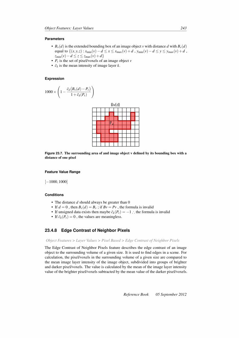
Object Features: Layer Values 243
Parameters
• Bv(d) is the extended bounding box of an image object v with distance d with Bv(d)equal to {(x,y,z) : xmin(v)−d ≤ x ≤ xmax(v)+ d , ymin(v)−d ≤ y ≤ ymax(v)+ d ,zmin(v)−d ≤ z≤ zmax(v)+d}
• Pv is the set of pixel/voxels of an image object v• ck is the mean intensity of image layer k.
Expression
1000×
(1−
ck(Bv(d)−Pv
)1+ ck(Pv)
)
Figure 23.7. The surrounding area of and image object v defined by its bounding box with adistance of one pixel
Feature Value Range
[−1000,1000]
Conditions
• The distance d should always be greater than 0• If d = 0 , then Bv(d) = Bv ; if Bv = Pv , the formula is invalid• If unsigned data exists then maybe ck(Pv) =−1 ∴ the formula is invalid• If ck(Pv) = 0 , the values are meaningless.
23.4.8 Edge Contrast of Neighbor Pixels
Object Features > Layer Values > Pixel Based > Edge Contrast of Neighbor Pixels
The Edge Contrast of Neighbor Pixels feature describes the edge contrast of an imageobject to the surrounding volume of a given size. It is used to find edges in a scene. Forcalculation, the pixel/voxels in the surrounding volume of a given size are compared tothe mean image layer intensity of the image object, subdivided into groups of brighterand darker pixel/voxels. The value is calculated by the mean of the image layer intensityvalue of the brighter pixel/voxels subtracted by the mean value of the darker pixel/voxels.
Reference Book 05 September 2012

244 Developer XD 2.0.4
Figure 23.8. Pixels of the surrounding area are compared to the mean image layer intensityof the image object v
Editable Parameters
Image Layer; Distance (the size of the surrounding area)
Parameters
• Pbrighter : {P : ck(x,y,z) > ck(v)} within the surrounding volume of image object vdefined by the bounding box (Bv(d))
• Pdarker : (Bv(d)) = {P : ck(x,y,z) < ck(v)} within the surrounding volume of imageobject v defined by the bounding box (Bv(d))
• (Bv(d)) is the extended bounding box of an image object v with distance d with{(x,y,z) : xmin(v)−d ≤ x≤ xmax(v)+d , ymin(v)−d ≤ y≤ ymax(v)+d , zmin(v)−d ≤ z≤ zmax(v)+d}
• ck(x,y,z) is the image layer intensity value at pixel/voxel (x,y,z)• ck(v) is the mean intensity of image layer k of all pixel/voxels forming an image
object v• Pv is the set of pixel/voxels of an image object v.
Expression
ck(Pbrighter)− ck(Pdarker)
Feature Value Range
[0,255]
Conditions
If Pbrighter(Bv(d)) = ∅ or Pdarker(Bv(d)) = ∅ then ck(v) is returned.
05 September 2012 Reference Book

Object Features: Layer Values 245
23.4.9 Std Dev. to Neighbor Pixels
Object Features > Layer Values > Pixel Based > Std Dev. to Neighbor Pixels
The standard deviation of layer intensity values of pixel/voxels within the surroundingvolume of a given size. The surrounding volume consists of the pixel/voxels locatedwithin the extended bounding box of an image object, but do no belong this image object.
Editable Parameters
Image Layer; Distance (edit the size of the surrounding volume)
Parameters
• Pv is the set of pixel/voxels of an image object v• (Bv(d)) is the extended bounding box of an image object v with distance d with{(x,y,z) : xmin(v)−d ≤ x≤ xmax(v)+d , ymin(v)−d ≤ y≤ ymax(v)+d , zmin(v)−d ≤ z≤ zmax(v)+d}.
Expression
σk(Bv(d)−Pv)
Feature Value Range[0,
cmaxk2
]
Conditions
If d = 0 , then Bv(d) = Bv and if Bv = Pv ∴ the formula is invalid.
23.4.10 Circular Mean
Object Features > Layer Values > Pixel Based > Circular Mean
Calculates the mean for all pixels within a ring around the center of an image object. Thethickness of the ring is defined by two radius values R1 and R2 .
Editable Parameters
• Layer• Radius Mode
– Number of Pixels – radius calculated from the number of pixels in the object
R =√
#Pxlπ
– Length – radius will equal half the length– Width – radius will equal half the width
Reference Book 05 September 2012

246 Developer XD 2.0.4
– User – radius will be specified in next parameter• Delta/User – defines delta in pixels for radius of number of pixels, length, width
and user modes. It can be positive, negative or zero• Second Radius Mode
– Same ( = R1 ), border – second radius will be equal to first radius. Pixels willbe used that form a thin border along the first radius
– None (=0), entire circle – second radius is set to zero. Entire circle of firstradius will be processed
– Relative to R1 – second radius is set to R1 . Users can define an offset (pos-itive, negative number or zero) to where the second radius will be extended(positive number) or shortened (negative number)
– User – radius will be specified in next parameter.
Parameters
• R1 is the inner radius of the ring• R2 is the outer radius of the ring• c is the center of the object• d(u,v) is the distance between objects.
Expression
(R1−0.5)≤ d(u,v)≤ (R2 +0.5)
Feature Value Range
[R1,R2]
Conditions
None
23.4.11 Circular StdDev
Object Features > Layer Values > Pixel Based > Circular StdDev
Calculates the standard deviation for all pixels within a ring around the center of an imageobject. The thickness of the ring is defined by two radius values, R1 and R2. Parametersand expressions are identical to the Circular Mean feature.
23.4.12 Circular Std Dev/Mean
Object Features > Layer Values > Pixel Based > Circular Std Dev/Mean
Calculates the ratio of the mean to the standard deviation for all pixels within a ringaround the center of an image object. The thickness of the ring is defined by two radiusvalues, R1 and R2. Parameters and expressions are identical to the Circular Mean feature.
05 September 2012 Reference Book
Object Features: Layer Values 247
23.4.13 Quantile
Object Features > Layer Values > Pixel Based > Quantile
Select the quantile of a layer.
Editable Parameters
• Select a layer from the Layer drop-down box, from which to extract the quantile• Insert a percentage value into the Quantile field (or get the value from a feature or
array item).
Parameters
The quantile is given by the element of the list Y with index equal to int(r)
• Y is the list of pixel intensities (sorted in increasing order)• N is the number of pixels• p is a number between 0 and 100 (i.e. a percentage)• The rank, r = p
100 ×N
Feature Value Range
[min layer value, max layer value]
23.5 To Neighbors
Object Features > Layer Values > To Neighbors
23.5.1 Mean Diff. to Neighbors
Object Features > Layer Values > To Neighbors > Mean Diff. to Neighbors
The Mean Diff. to Neighbors feature describes the difference between an image objectand its neighbor image objects, in terms of mean layer intensity values. For each neigh-boring image object of the image object of interest, the mean layer difference is computedand weighted as follows:
• If the neighboring image objects are direct neighbors (feature distance = 0), thelength of the border between the image objects is used for weighting
• If the neighborhood of image objects is defined within a certain perimeter aroundthe image object of interest (feature distance > 0), the area covered by the neighborimage objects is used for weighting.
Reference Book 05 September 2012

248 Developer XD 2.0.4
Editable Parameters
• Image Layer• Feature Distance: Radius of the perimeter in pixel/voxel. Direct neighbors have a
value of 0.
Parameters
• u,v are image objects• b(v,u) is the length of the common border between v and u• ck is the mean intensity of image layer k• cmin
k is the darkest possible intensity value of image layer k• cmax
k is the brightest possible intensity value of image layer k• #Pu is the total number of pixels/voxels contained in Pv• d is the distance between neighbors• w is the image layer weight with w = ∑u∈Nv(d) wu
• wu is the weight of image object u with wu = {b(v,u),d=0)#Pu,d>0
• Nv is the direct neighbor to image object v with Nv : {u ∈Vi : ∃(x,y) ∈ Pv∃(x′,y′) ∈Pu : (x′y′) ∈ N4(x,y)}
• Nv(d) is a neighbor to v at a distance d with Nv(d) = {u ∈Vi : d(v,u)≤ d}.
Expression
∆k(v) =1w ∑
uεNv(d)wu(ck(v)− ck(u)
)
Figure 23.9. Direct neighbors (x) and the neighborhood within perimeter d of image object v
Feature Value Range
[cmink ,cmax
k ]
Conditions
If w = 0 the feature value is 0; therefore the formula is invalid.
05 September 2012 Reference Book

Object Features: Layer Values 249
23.5.2 Mean Diff. to Neighbors (Abs)
Object Features > Layer Values > To Neighbors > Mean Diff. to Neighbors (Abs.)
The Mean Diff. to Neighbors (Abs) feature describes the difference between an imageobject and its neighbor image objects, in terms of their mean layer intensity values. It iscalculated in a similar way to the Mean Diff. to Neighbors feature; the only difference isthat absolute values of differences are averaged.
Editable Parameters
• Image Layer• Feature Distance – the radius of the perimeter in pixels. Direct neighbors have a
value of 0.
Parameters
• u,v are image objects• b(v,u) is the length of the common border between v and u• ck is the mean intensity of image layer k• cmin
k is the darkest possible intensity value of image layer k• cmax
k is the brightest possible intensity value of image layer k• crange
k is the data range of image layer k• d is the distance between neighbors• #Pu is the total number of pixels contained in Pu• w is the image layer weight with w = ∑u∈Nv(d) wu
• wu is the weight of image object u with wu = {b(v,u),d=0)#Pu,d>0
• Nv is the direct neighbor to image object v with Nv : {u ∈Vi : ∃(x,y) ∈ Pv∃(x′,y′) ∈Pu : (x′y′) ∈ N4(x,y)}
• Nv(d) is a neighbor to v at a distance d with Nv(d) = {u ∈Vi : d(v,u)≤ d}.
Expression
∆k(v) =1w ∑
u∈Nv(d)wu(|ck(v)− ck(u)|
)
Feature Value Range
[0,crangek ]
Conditions
If w = 0 the feature value is 0; therefore the formula is invalid.
Reference Book 05 September 2012

250 Developer XD 2.0.4
23.5.3 Mean Diff. to Darker Neighbors
Object Features > Layer Values > To Neighbors > Mean Diff. to Darker Neighbors
The Mean Diff. to Darker Neighbors feature describes the difference between an imageobject and its darker neighbor image objects, in terms of their mean layer intensity values.In contrast to the Mean Diff. to Neighbors feature, only direct neighbor image objectsare counted that have a lower mean layer value than the image object of interest.
Editable Parameters
Image Layer
Parameters
• u,v are image objects• b(v,u) is the length of the common border between v and u• ck is the mean intensity of image layer k• cmin
k is the darkest possible intensity value of image layer k• cmax
k is the brightest possible intensity value of image layer k• crange
k is the data range of image layer k , with crangek = cmax
k − cmink
• w is the image layer weight with w = ∑u∈Nv(d) wu , where wu is the weight of image
object u with wu = {b(v,u),d=0)#Pu,d>0
• Nv is the direct neighbor to image object v with Nv : {u ∈Vi : ∃(x,y) ∈ Pv∃(x′,y′) ∈Pu : (x′y′) ∈ N4(x,y)}
• NDv is the darker direct neighbor to v , with ND
v {u ∈ Nv : ck(u) < ck(v)}.
Expression
∆Dk (v) =
1w ∑
uεNDv
wu(ck(v)− ck(u)
)
Feature Value Range
[−crangek ,crange
k ]
Conditions
If w = 0 the feature value is 0; therefore the formula is invalid. If NDv = 0 the formula is
invalid.
23.5.4 Mean Diff. to Brighter Neighbors
Object Features > Layer Values > To Neighbors > Mean Diff. to Brighter Neighbors
The Mean Diff. to Brighter Neighbors feature describes the difference between an imageobject and its darker neighbor image objects, in terms of their mean layer intensity values.
05 September 2012 Reference Book

Object Features: Layer Values 251
In contrast to the Mean Diff. to Neighbors feature, only direct neighbor image objectsare counted that have a mean layer value less than that of the image object of interest.
Editable Parameters
• Image Layer
Parameters
• u,v are image objects• b(v,u) is the length of the common border between v and u• ck is the mean intensity of image layer k• cmin
k is the darkest possible intensity value of image layer k• cmax
k is the brightest possible intensity value of image layer k• crange
k is the data range of image layer k , with crangek = cmax
k − cmink
• w is the image layer weight with w = ∑u∈Nv(d) wu , where wu is the weight of image
object u with wu = {b(v,u),d=0)#Pu,d>0
• Nv is the direct neighbor to image object v with Nv : {u ∈Vi : ∃(x,y) ∈ Pv∃(x′,y′) ∈Pu : (x′y′) ∈ N4(x,y)}
• NBv is the brighter direct neighbor to v , with NB
v {u ∈ Nv : ck(u) < ck(v)}.
Expression
∆Bk (v) =
1w ∑
uεNBv
wu(ck(v)− ck(u)
)
Feature Value Range
[−crangek ,crange
k ]
23.5.5 Number of Brighter Objects
Object Features > Layer Values > To Neighbors > Number of Brighter Objects
The Number of Brighter Objects feature counts the neighboring objects – those objectswith a common border – with a higher intensity. Neighboring objects with the same meanvalue are not counted.
23.5.6 Number of Darker Objects
Object Features > Layer Values > To Neighbors > Number of Darker Objects
The Number of Darker Objects feature counts the neighboring objects – those objectswith a common border – with a lower intensity. Neighboring objects with the same meanvalue are not counted.
Reference Book 05 September 2012
252 Developer XD 2.0.4
23.5.7 Rel. Border to Brighter Neighbors
Object Features > Layer Values > To Neighbors > Rel. Border to Brighter Neighbors
The Rel. Border to Brighter Neighbors feature describes the extent to which an imageobject is surrounded by brighter or darker direct neighbor image objects. In a given imagelayer, it is the ratio of the shared image border of an image object to the total border. Avalue of 1 that the image object is surrounded completely by brighter neighbors; a valueof 0 means it has no brighter direct neighbors.
Editable Parameters
Image Layer
Parameters
• NBv is the darker direct neighbor to v , with NB
v {u ∈ Nv : ck(u) < ck(v)}• bv is the image object border length• b(v,u) is the length of common border between v and u.
Expression
∑u∈NB
v
b(v,u)bv
Feature Value Range
[0,1]
23.6 To Superobject
Object Features > Layer Values > To Superobject
23.6.1 Mean Diff. to Superobject
Object Features > Layer Values > To Superobject > Mean Diff. to Superobject
The difference between the mean layer intensity value of an image object and the meanlayer intensity value of its superobject.
Editable Parameters
• Image Layer• Image Object Level Distance – the upward distance of image object levels in the
image object hierarchy between the image object and the superobject.
05 September 2012 Reference Book
Object Features: Layer Values 253
Parameters
• ck is the mean intensity of image layer k• crange
k is the data range of image layer k , with crangek = cmax
k − cmink
• Sv(d) is the sub-object of image object v with level distance d• Uv(d) is the superobject of image object v with level distance d.
Expression
ck(v)− ck(Uv(d)
)Feature Value Range
[−crangek ,crange
k ]
23.6.2 Ratio to Superobject
Object Features > Layer Values > To Superobject > Ratio to Superobject
The ratio of the mean layer intensity value of an image object and the mean layer intensityvalue of its superobject.
Editable Parameters
• Image Layer• Image Object Level Distance – the upward distance of image object levels in the
image object hierarchy between the image object and the superobject.
Parameters
• ck is the mean intensity of image layer k• Uv(d) is the superobject of image object v with level distance d
Expression
ck(v)ck(Uv(d)
)Feature Value Range
[0,∞]
Conditions
If Uv(d) = ∅ or Uv(d) = 0→ ∞ the expression is undefined.
Reference Book 05 September 2012

254 Developer XD 2.0.4
23.6.3 Std. Dev. Diff. to Superobject
Object Features > Layer Values > To Superobject > Std. Dev. Diff to Superobject
Editable Parameters
• Image Layer• Image Object Level Distance – the upward distance of image object levels in the
image object hierarchy between the image object and the superobject.
Parameters
• σk(v) is the standard deviation of intensity values of image layer k of allpixel/voxels forming an image object v
• Uv(d) is the superobject of image object v with level distance d• crange
k is the data range of image layer k with crangek = cmax
k − cmink .
Expression
σk(v)−σk(Uv(d)
)Feature Value Range
[−12
crangek ,
12
crangek ]
Condition
If Uv(d) = ∅ the expression is undefined.
23.6.4 Std. Dev. Ratio to Superobject
Object Features > Layer Values > To Superobject > Std. Dev Ratio to Superobject
The ratio of the standard deviation of the layer intensity of an image object to the standarddeviation of the layer intensity of its superobject.
Editable Parameters
• Image Layer• Image Object Level Distance – the upward distance of image object levels in the
image object hierarchy between the image object and the superobject.
Parameters
• σk(v) is the standard deviation of intensity values of image layer k of allpixel/voxels forming an image object v
• Uv(d) is the superobject of image object v with level distance d
05 September 2012 Reference Book

Object Features: Layer Values 255
Expression
σk(v)σk(Uv(d))
Feature Value Range
[0,∞]
Conditions
• If Uv(d) = ∅ or Uv(d) = 0→ ∞ the expression is undefined.• If σv(Uv(d)) = 0⇒ the standard deviation ratio to (Uv(d)) = 1.
23.7 To Scene
Object Features > Layer Values > To Scene
23.7.1 Mean Diff. to Scene
Object Features > Layer Values > To Scene > Mean Diff. to Scene
Editable Parameters
• Image Layer
Parameters
• ck(v) is the mean intensity of image layer k of all pixels forming an image object v• ck is the mean intensity of image layer k• crange
k is the data range of image layer k , with crangek = cmax
k − cmink
Expression
ck(v)− ck
Feature Value Range
[−crangek ,crange
k ]
23.7.2 Ratio To Scene
Object Features > Layer Values > To Scene > Ratio to Scene
Reference Book 05 September 2012

256 Developer XD 2.0.4
Editable Parameter
• Image Layer
Parameters
• ck(v) is the mean intensity of image layer k of all pixels forming an image object v• ck is the mean intensity of image layer k.
Expression
ck(v)ck
Feature Value Range
[−∞,∞]
Condition
If ck = 0⇔ the expression is undefined.
23.8 Hue, Saturation, Intensity
Object Features > Layer Values > Hue, Saturation, Intensity
Hue, Saturation, and Intensity features convert RGB color space values to HSI values.
23.8.1 HSI Transformation
Editable Parameters
• Layer red, layer green, layer blue – for each parameter, assign a correspondingimage layer from the drop-down list. By default these are the first three imagelayers of the scene.
• Output: Select the type of HSI transformation feature to be created: hue (color),saturation or intensity (brightness).
Parameters
• RGB values are expressed as numbers from 0 to 1• max is the greatest of the RGB values• min is the smallest of the RGB values.
05 September 2012 Reference Book

Object Features: Layer Values 257
Expression
H =
undefined if max = min
60◦× G−Bmax−min
360◦ if max = R
60◦× B−Rmax−min +120◦
360◦ if max = G
60◦× R−Gmax−min +240◦
360◦ if max = B
Feature Value Range
[0,1]
Reference Book 05 September 2012

24 Object Features: Geometry
Object Features > Geometry
Geometry features are based on an image object’s shape, calculated from the pixels thatform it. Because images are raster-based, geometry features may be rotation variant: afterimage objects are rotated, different feature values may arise.
24.1 Extent
Object Features > Geometry > Extent
24.1.1 Area
Object Features > Geometry > Extent > Area
The number of pixels forming an image object. If unit information is available, the num-ber of pixels can be converted into a measurement. In scenes that provide no unit infor-mation, the area of a single pixel is 1 and the area is simply the number of pixels thatform it. If the image data provides unit information, the area can be multiplied using theappropriate factor.
Parameters
• Av is the area of image object v• #Pv is the total number of pixels contained in Pv• u is the pixel size in co-ordinate system units. If the unit is a pixel, then u = 1.
Expression
Av = #Pv×u2
Feature Value Range
[0,scene size]
259

260 Developer XD 2.0.4
24.1.2 Border Length [for 2D Image Objects]
Object Features > Geometry > Extent > Border Length
The border length of an image object is defined as the sum of edges of the image objectshared with other image objects, or situated on the edge of the entire scene. For a torus –and other image objects with holes – the border length is the sum of the inner and outerborders.
Parameters
• bv is the border length of image object• bo is the length of outer border• bi is the length of inner border
Expression
bv = bo +bi
Figure 24.1. Border length of an image object v , or between two objects v and u
Figure 24.2. Inner and outer border length of a torus image object
Feature Value Range
[0,∞]
05 September 2012 Reference Book

Object Features: Geometry 261
24.1.3 Border Length [for 3D Image Objects]
Object Features > Geometry > Extent > Border Length
The border length of a 3D image object is the sum of border lengths of all image objectslices, multiplied by the spatial distance between them.
Image object slices are 2D pieces of the image object in each slice. The border lengthof an image object slice is defined as the sum of edges shared with other image objectpieces, or are situated on the edge of the entire slice. For a torus and other image objectswith holes the border length sums the inner and outer border.
Parameters
• bv is the border length of image object v• bv(slice) is the border length of image object slice• bv(z) is the border length of image object in z -direction• uslices is the spatial distance between slices in the co-ordinate system unit• bo is the length of the outer border• bi is the length of the inner border
Expression
bv =
(#(slices)
∑n=1
bv(slice)
)×uslices +bv(z)
where bv(slice) = bo +bi
Feature Value Range
[0,∞]
24.1.4 Length [for 2D Image Objects]
Object Features > Geometry > Extent > Length
The length of a 2D image object is calculated using the length-to-width ratio.
Parameters
• #Pv is the total number of pixels contained in Pv• γv is the length-width ratio of an image object v
Expression√#Pv · γv
Reference Book 05 September 2012

262 Developer XD 2.0.4
Feature Value Range
[0,∞]
24.1.5 Length [for 3D Image Objects]
Object Features > Geometry > Extent > Length
The length of an image object is the largest of three eigenvalues of a rectangular 3Dspace that is defined by the same volume, and same proportions of eigenvalues, as theimage object. The length of an image object can be smaller or equal than the largest ofdimensions of the smallest rectangular 3D space enclosing the image object.
Feature Value Range
[0,∞]
24.1.6 Length/Thickness
Object Features > Geometry > Extent > Length/Thickness
The length-to-thickness ratio of an image object.
Parameters
• Length of the image object• Thickness of the image object
Expression
LengthThickness
Feature Value Range
[0,∞]
24.1.7 Length/Width [for 2D Image Objects]
Object Features > Geometry > Extent > Length/Width
The length-to-width ratio of an image object. There are two methods to approximate this:
1. The ratio of length to width is identical to the ratio of the eigenvalues of the covariancematrix, with the larger eigenvalue being the numerator of the fraction:
γEVv =
λ1(v)λ2(v)
05 September 2012 Reference Book
Object Features: Geometry 263
2. The ratio of length to width can also be approximated using the bounding box:
γBBv =
(kbb′
v)2
#Pv
Both calculations are compared; the smaller of both results is returned as the featurevalue.
Parameters
• #Pv is the Size of a set of pixels of an image object v• λ1λ2 are eigenvalues• γEV
v is the ratio length of v of the eigenvalues• γBB
v is the ratio length of v of the bounding box• γv is the length-width ratio of an image object v• kBB′
v• hBB′
v• a is the bounding box fill rate• #Pxl• h• w is the image layer weight
• kbb1v =
√(kbb′
v )2 +(1−a)(hbb′v )2
• a = #Pvkbb′
v −hbb′v
• k ·h = #Pv⇒ k = #Pvw ,h = #Pv
k ⇒kw = k2
#Pxl= #Pxl
w2
Expression
γv = minγEVv ,maxγ
BBv
Feature Value Range
[0,∞]
24.1.8 Length/Width [for 3D Image Objects]
Object Features > Geometry > Extent > Length/Width
The length-to-width ratio of an image object.
Parameters
• Length of the image object• Width of the image object
Expression
LengthWidth
Reference Book 05 September 2012

264 Developer XD 2.0.4
Feature Value Range
[0,∞]
24.1.9 Number of Pixels
Object Features > Geometry > Extent > Number of Pixels
The number of pixels forming an image object. Unit information is not taken into account.
Parameters
• #Pv is the total number of pixels contained in Pv
Feature Value Range
[0,scene size]
24.1.10 Thickness
Object Features > Geometry > Extent > Thickness
The thickness of an image object is the smallest of three eigenvalues of a rectangular 3Dspace with the same volume as the image object and the same proportions of eigenvaluesas the image object. The thickness of an image object can be smaller or equal to thesmallest of dimensions of the smallest rectangular 3D space enclosing the image object.
Feature Value Range
[0,∞]
24.1.11 Volume
Object Features > Geometry > Extent > Volume
The number of voxels forming an image object rescaled by using unit information for xand y co-ordinates and distance information between slices.
Parameters
• Vv is the volume of image object v• #Pv is the total number of voxels contained in Pv• u is the size of a slice pixel in the co-ordinate system unit• uslices is the spatial distance between slices in the co-ordinate system unit
05 September 2012 Reference Book

Object Features: Geometry 265
Expression
Vv = #Pv×u2×uslices
Feature Value Range
[0,scene size]
24.1.12 Width [for 2D Image Objects]
Object Features > Geometry > Extent > Width
The width of an image object is calculated using the length-to-width ratio.
Parameters
• #Pv is the total number of pixels contained in Pv• γv is the length/width ratio of an image object v
Expression
#Pv
γv
Feature Value Range
[0,∞]
24.1.13 Width [for 3D Image Objects]
Object Features > Geometry > Extent > Width
The width of an image object is the mid-point of three eigenvalues of a rectangular 3Dspace with the same volume as the image object and the same proportions of eigenvaluesas the image object. The width of an image object can be smaller or equal to the mid-pointof dimensions of the smallest rectangular 3D space enclosing the image object.
Feature Value Range
[0,∞]
24.2 Shape
Object Features > Geometry > Shape
Reference Book 05 September 2012
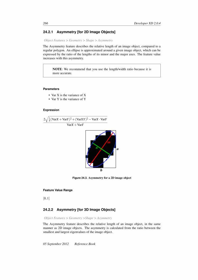
266 Developer XD 2.0.4
24.2.1 Asymmetry [for 2D Image Objects]
Object Features > Geometry > Shape > Asymmetry
The Asymmetry feature describes the relative length of an image object, compared to aregular polygon. An ellipse is approximated around a given image object, which can beexpressed by the ratio of the lengths of its minor and the major axes. The feature valueincreases with this asymmetry.
NOTE: We recommend that you use the length/width ratio because it ismore accurate.
Parameters
• Var X is the variance of X• Var Y is the variance of Y
Expression
2√
14 (VarX +VarY )2 +(VarXY )2−VarX ·VarY
VarX +VarY
Figure 24.3. Asymmetry for a 2D image object
Feature Value Range
[0,1]
24.2.2 Asymmetry [for 3D Image Objects]
Object Features > Geometry >Shape > Asymmetry
The Asymmetry feature describes the relative length of an image object, in the samemanner as 2D image objects. The asymmetry is calculated from the ratio between thesmallest and largest eigenvalues of the image object.
05 September 2012 Reference Book

Object Features: Geometry 267
Parameters
• λmin is the minimal eigenvalue• λmax is the maximal eigenvalue
Expression
1−
√λmin
λmax
Figure 24.4. Asymmetry based on maximal and minimal eigenvalues
Feature Value Range
[0,1]
24.2.3 Border Index
Object Features > Geometry > Shape > Border Index
The Border Index feature describes how jagged an image object is; the more jagged,the higher its border index. This feature is similar to the Shape Index feature, but theBorder Index feature uses a rectangular approximation instead of a square. The smallestrectangle enclosing the image object is created and the border index is calculated as theratio between the border lengths of the image object and the smallest enclosing rectangle.
Parameters
• bv is the image object border length• lv is the length of an image object v• wv is the width of an image object v
Expression
bv
2(lv +wv)
Reference Book 05 September 2012

268 Developer XD 2.0.4
Figure 24.5. Border index of an image object v
Feature Value Range
[1,∞] ; 1 = ideal.
24.2.4 Compactness [for 2D Image Objects]
Object Features > Geometry > Shape > Compactness
The Compactness feature describes how compact an image object is. It is similar toBorder Index, but is based on area. However, the more compact an image object is, thesmaller its border appears. The compactness of an image object is the product of thelength and the width, divided by the number of pixels.
Parameters
• lv is the length of an image object v• wv is the width of an image object v• #Pv is the total number of pixels contained in Pv
Expression
2λ1×2λ2×2λ3
Vv
Figure 24.6. Compactness of an image object v
05 September 2012 Reference Book

Object Features: Geometry 269
Feature Value Range
[0,∞] ; 1 = ideal.
24.2.5 Compactness [for 3D Image Objects]
Object Features > Geometry >Shape > Compactness
Compactness describes how compact a 3D image object is. Appropriately scaled eigen-vectors of an image object’s covariance matrix provide a rough figure of the object’sextent in three dimensions.
A figure for the compactness of a 3D image object is calculated by a scaled product ofits three eigenvalues (2×λ1,2×λ2,2×λ3) divided by the number of its pixel/voxel. Weinclude a factor of 2 with each eigenvalue, since λi× eigenvectors represent otherwisehalf axes of an ellipsoid defined by its covariance matrix. The chosen approach thereforeprovides an estimate of a cuboid occupied by the object.
Parameters
• λ1 is eigenvalue 1 of a 3D image object v• λ2 is the eigenvalue 2 of a 3D image object v• λ3 is eigenvalue 3 of a 3D image object v• Vv is the volume of image object v
Expression
2λ1×2λ2×2λ3
Vv
Feature Value Range
[0,∞] ; 1 = ideal.
24.2.6 Density [for 2D Image Objects]
Object Features > Geometry > Shape > Density
The Density feature describes the distribution in space of the pixels of an image object.In Definiens Developer XD 2.0.4 the most “dense” shape is a square; the more an objectis shaped like a filament, the lower its density. The density is calculated by the num-ber of pixels forming the image object divided by its approximated radius, based on thecovariance matrix.
Parameters
•√
#Pv is the diameter of a square object with #Pv pixels•√
VarX +VarY is the diameter of the ellipse
Reference Book 05 September 2012

270 Developer XD 2.0.4
Expression
√#Pv
1+√
VarX +VarY
Feature Value Range
[0,depending on shape of image object]
24.2.7 Density [for 3D Image Objects]
Object Features > Geometry > Shape > Density
Using the same principle as Density [for 2D Image Objects], the most “dense” shape fora 3D object is a cube. The more filament-shaped an image object is, the lower its density.The value is calculated by dividing the edge of the volume of a fitted cuboid by the radiusof a fitted sphere.
Parameters
• Vv is the volume of image object v• 3√
Vv is the edge of the volume fitted cuboid•√
Var(X)+Var(Y )+Var(Z) is the radius of the fitted sphere
Expression
3√
Vv√Var(X)+Var(Y )+Var(Z)
Feature Value Range
[0,depending on shape of image object]
24.2.8 Elliptic Fit [for 2D Image Objects]
Object Features > Geometry > Shape > Elliptic Fit
The Elliptic Fit feature describes how well an image object fits into an ellipse of similarsize and proportions. While 0 indicates no fit, 1 indicates a perfect fit.
The calculation is based on an ellipse with the same area as the selected image object. Theproportions of the ellipse are equal to the length to the width of the image object. Thearea of the image object outside the ellipse is compared with the area inside the ellipsethat is not filled by the image object.
05 September 2012 Reference Book

Object Features: Geometry 271
Parameters
• εv(x,y) is the elliptic distance at a pixel (x,y)• Pv is the set of pixels of an image object v• #Pv is the total number of pixels contained in Pv
Expression
ϕ = 2 ·#{(x,y)εPv : εv(x,y)≤ 1
}#Pv
−1
Figure 24.7. Elliptic fit of an image object v
Feature Value Range
[0,1] ; 1 = complete fitting, 0 = <50% fit.
24.2.9 Elliptic Fit [for 3D Image Objects]
Object Features > Geometry > Shape > Elliptic Fit
The Elliptic Fit feature describes how well an image object fits into an ellipsoid of similarsize and proportions. While 0 indicates no fit, 1 indicates a perfect fit.
The calculation is based on an ellipsoid with the same volume as the considered imageobject. The proportions of the ellipsoid are equal to the proportions of the length, widthand thickness of the image object. The volume of the image object outside the ellipsoid iscompared with the volume inside the ellipsoid that is not filled out with the image object.
Parameters
• εv(x,y,z) is the elliptic distance at a pixel (x,y,z)• Pv is the set of pixels of an image object v• #Pv is the total number of pixels contained in Pv
Expression
ϕ = 2 ·#{(x,y,z)εPv : εv(x,y,z)≤ 1
}#Pv
−1
Reference Book 05 September 2012

272 Developer XD 2.0.4
Figure 24.8. Elliptic fit of an image object v
Feature Value Range
[0,1] ; 1 = complete fitting, whereas 0 = < 50% voxels.
24.2.10 Main Direction [for 2D Image Objects]
Object Features > Geometry > Shape > Elliptic Fit > Main Direction
The Main Direction feature of an image object is defined as the direction of the eigenvec-tor belonging to the larger of the two eigenvalues, derived from the covariance matrix ofthe spatial distribution of the image object.
Parameters
• VarX is the variance of X• VarY is the variance of Y• λ1 is the eigenvalue
Expression
180◦
πtan−1(VarXY,λ1−VarY )+90◦
Figure 24.9. The main direction is based on the direction of the larger eigenvector
05 September 2012 Reference Book

Object Features: Geometry 273
Feature Value Range
[0,180]
24.2.11 Main Direction [for 3D Image Objects]
Object Features > Geometry > Shape > Main Direction
The Main Direction feature of a three-dimensional image object is computed as follows:
1. For each (2D) image object slice, the centers of gravities are calculated.2. The co-ordinates of all centers of gravities a reused to calculate a line of best fit,
according to the Weighted Least Square method.3. The angle a between the resulting line of best fit and the z-axis is returned as feature
value.
Figure 24.10. The line of best fit (blue) calculated from centers of gravity of image objectslices (light blue)
Feature Value Range
[0,90]
24.2.12 Radius of Largest Enclosed Ellipse [for 2D Image Objects]
Object Features > Geometry > Shape > Radius of Largest Enclosed Ellipse
Reference Book 05 September 2012

274 Developer XD 2.0.4
The Radius of Largest Enclosed Ellipse feature describes how similar an image object isto an ellipse. The calculation uses an ellipse with the same area as the object and basedon the covariance matrix. This ellipse is scaled down until it is totally enclosed by theimage object. The ratio of the radius of this largest enclosed ellipse to the radius of theoriginal ellipse is returned as feature value.
Parameters
• εv(x,y) is the elliptic distance at a pixel (x,y)
Expression
εv(xo,yo) , where (xo,yo) = min εv(x,y),(x,y) /∈ Pv
Figure 24.11. Radius of the largest enclosed ellipse of in image object v , for a 2D image object
Feature Value Range
[0,∞]
24.2.13 Radius of Largest Enclosed Ellipse [for 3D Image Objects]
Object Features > Geometry > Shape > Radius of Largest Enclosed Ellipse
The Radius of Largest Enclosed Ellipse feature describes how much the shape of animage object is similar to an ellipsoid. The calculation is based on an ellipsoid with thesame volume as the object and based on the covariance matrix. This ellipsoid is scaleddown until it is totally enclosed by the image object. The ratio of the radius of this largestenclosed ellipsoid to the radius of the original ellipsoid is returned as feature value.
Parameters
• εv(x,y,z) is the elliptic distance at a pixel (x,y,z)
Expression
εv(xo,yo,zo) , where (xo,yo,zo) = min εv(x,y,z),(x,y,z) /∈ Pv
05 September 2012 Reference Book

Object Features: Geometry 275
Figure 24.12. Radius of the largest enclosed ellipse of in image object v , for a 3D image object
Feature Value Range
[0,∞]
24.2.14 Radius of Smallest Enclosing Ellipse [for 2D Image Objects]
Object Features > Geometry >Shape > Radius of Smallest Enclosing Ellipse
The Radius of Smallest Enclosing Ellipse feature describes how much the shape of animage object is similar to an ellipse. The calculation is based on an ellipse with the samearea as the image object and based on the covariance matrix. This ellipse is enlarged untilit encloses the image object in total. The ratio of the radius of this smallest enclosingellipse to the radius of the original ellipse is returned as feature value.
Figure 24.13. Radius of the smallest enclosed ellipse of in image object v , for a 2D imageobject
Parameters
• εv(x,y) is the elliptic distance at a pixel (x,y)
Expression
εv(xo,yo) , where (xo,yo) = max εv(x,y),(x,y) /∈ Pv
Reference Book 05 September 2012

276 Developer XD 2.0.4
Feature Value Range
[0,∞]
24.2.15 Radius of Smallest Enclosing Ellipse [for 3D Image Objects]
Object Features > Geometry > Shape > Radius of Smallest Enclosing Ellipse
The Radius of Smallest Enclosing Ellipse feature describes how much the shape of animage object is similar to an ellipsoid. The calculation is based on an ellipsoid with thesame volume as the image object and based on the covariance matrix. This ellipsoid isenlarged until it encloses the image object in total. The ratio of the radius of this smallestenclosing ellipsoid to the radius of the original ellipsoid is returned as feature value.
Figure 24.14. Radius of the smallest enclosed ellipse of in image object v , for a 3D imageobject
Parameters
• εv(x,y,z) is the elliptic distance at a pixel (x,y,z)
Expression
εv(xo,yo,zo) , where (xo,yo,zo) = max εv(x,y,z),(x,y,z) ∈ σPv
Feature Value Range
[0,∞]
24.2.16 Rectangular Fit [for 2D Image Objects]
Object Features > Geometry > Shape > Rectangular Fit
The Rectangular Fit feature describes how well an image object fits into a rectangle ofsimilar size and proportions. While 0 indicates no fit, 1 indicates for a complete fittingimage object.
05 September 2012 Reference Book

Object Features: Geometry 277
The calculation is based on a rectangle with the same area as the image object. Theproportions of the rectangle are equal to the proportions of the length to width of theimage object. The area of the image object outside the rectangle is compared with thearea inside the rectangle.
Parameters
• ρv(x,y) is the elliptic distance at a pixel (x,y)
Expression{#(x,y)εPv : ρv(x,y)≤ 1
}#Pv
Figure 24.15. Rectangular fit of an image object v
Feature Value Range
[0,1] ; where 1 is a perfect rectangle.
24.2.17 Rectangular Fit [for 3D Image Objects]
Object Features > Geometry > Shape > Rectangular Fit
The Rectangular Fit feature describes how well an image object fits into a cuboid ofsimilar size and proportions. While 0 indicates no fit, 1 indicates a perfect fit.
The calculation is based on a cuboid with the same volume as the considered imageobject. The proportions of the cuboid are equal to the proportions of the length to widthto thickness of the image object. The volume of the image object outside the rectangle iscompared with the volume inside the cuboid that is not filled out with the image object.
Parameters
• ρv(x,y,z) is the rectangular distance at a pixel (x,y,z)• #Pv is the total number of pixels contained in Pv
Reference Book 05 September 2012

278 Developer XD 2.0.4
Expression{#(x,y,z)εPv : ρv(x,y,z)≤ 1
}#Pv
Feature Value Range
[0,1] ; 1 = complete fitting, whereas 0 = 0% fits inside the rectangular approximation.
24.2.18 Roundness [for 2D Image Objects]
Object Features > Geometry > Shape > Roundness
The Roundness feature describes how similar an image object is to an ellipse. It is calcu-lated by the difference of the enclosing ellipse and the enclosed ellipse. The radius of thelargest enclosed ellipse is subtracted from the radius of the smallest enclosing ellipse.
Parameters
• εmaxv is the radius of the smallest enclosing ellipse
• εminv is the radius of the largest enclosed ellipse
Expression
εmaxv − ε
minv
Figure 24.16. Roundness feature of image object v
Feature Value Range
[0,∞] ; 0 = ideal.
05 September 2012 Reference Book

Object Features: Geometry 279
24.2.19 Roundness [for 3D Image Objects]
Object Features > Geometry > Shape > Roundness
The Roundness feature describes how much the shape of an image object is similar to anellipsoid. The more the shape of an image object is similar to an ellipsoid, the lower itsroundness.
It is calculated by the difference of the enclosing ellipsoid and the enclosed ellipsoid.The radius of the largest enclosed ellipsoid is subtracted from the radius of the smallestenclosing ellipsoid.
Parameters
• εmaxv is the radius of the smallest enclosing ellipsoid
• εminv is the radius of the largest enclosed ellipsoid
Expression
εmaxv − ε
minv
Feature Value Range
[0,∞] ; 0 = ideal.
24.2.20 Shape Index [for 2D Image Objects]
Object Features > Geometry > Shape > Shape Index
The Shape index describes the smoothness of an image object border. The smoother theborder of an image object is, the lower its shape index. It is calculated from the BorderLength feature of the image object divided by four times the square root of its area.
Parameters
• bv is the image object border length• 4√
#Pv is the border of square with area #Pv
Expression
bv
4√
#Pv
Feature Value Range
[1,∞] ; 1 = ideal.
Reference Book 05 September 2012

280 Developer XD 2.0.4
Figure 24.17. Shape index of an image object v
24.2.21 Shape Index [for 3D Image Objects]
Object Features > Geometry > Shape > Shape Index
The Shape Index describes the smoothness of the surface of an image object. Thesmoother the surface of an image object is, the lower its shape index. It is calculatedfrom the Border Length feature of the image object divided by the volume of the imageobject.
Parameters
• bv is the image object border length• Vv is the volume of image object v
Expression
bv
Vv
Feature Value Range
[0,1]
24.3 To Super-Object
Object Features > Geometry > To Super-Object
Use the To Super-Object feature to describe an image object by its shape and relationshipto one of its superobjects, where appropriate. Editing the feature distance determineswhich superobject is referred to. When working with thematic layers these features canbe of interest.
24.3.1 Rel. Area to Super-Object
Object Features > Geometry > To Super-Object > Rel. Area to Super-Object
05 September 2012 Reference Book

Object Features: Geometry 281
The area of an image object divided by the area of its superobject. If the feature value is1, the image object is identical to its superobject. Use this feature to describe an imageobject in terms of the amount of area it shares with its superobject.
Parameters
• #Pv is the total number of pixels contained in Pv• #PUv(d) is the the size of the superobject of v in the image object level of the level
distance d
Expression
#Pv
#PUv(d)
Conditions
If Uv(d) = ∅ ∴ the formula is undefined.
Feature Value Range
[0,1]
24.3.2 Rel. Rad. Position to Super-Object
Object Features > Geometry > To Super-Object > Rel. Rad. Position to Super-Object
This value is calculated by dividing the distance between the center of a selected imageobject and the center of its superobject, by the distance of the center of the most distantimage object (which has the same superobject). Use this feature to describe an imageobject by its position relative to the center of its superobject.
Parameters
• #Pv is the total number of pixels contained in Pv• #PUv(d) is the the size of the superobject of an image object v• dg(v,Uv(d)) is the distance of v to the center of gravity of the superobject Uv(d)
Expression
dg(v,Uv(d)
)max
u∈SUv(d)(d)
dg(u,Uv(d)
)
Conditions
If Uv(d) = ∅ ∴ the formula is undefined.
Reference Book 05 September 2012

282 Developer XD 2.0.4
Figure 24.18. Relative radial position to superobject
Feature Value Range
[0,1]
24.3.3 Rel. Inner Border to Super-Object
Object Features > Geometry > To Super-Object > Rel. Inner Border to Super-Object
This feature is calculated by dividing the sum of the border shared with other imageobjects, which have the same superobject, by the total border of the image object. If therelative inner border to the superobject is 1, the image object of concern is not situated onthe border of its superobject. Use this feature to describe how much of an image object issituated at the edge of its superobject.
Parameters
• Nu(v) are neighbors of v that exist within the superobject Nu(v) : {u ∈ Nv : Uu(d)−Uv(d)}
• bv is the image object border length
Expression
∑u∈NU (v) b(v,m)bv
Conditions
If the feature range is 0 then v = Uv(d)
If the feature range is 1 then v is an inner object.
Feature Value Range
[0,1]
05 September 2012 Reference Book

Object Features: Geometry 283
Figure 24.19. Relative inner border of an image object v to superobject u
24.3.4 Distance to Super-Object Center
Object Features > Geometry > To Super-Object > Distance to Super-Object Center
The distance of an image object’s center to the center of its superobject. The calculateddistance is based upon segmentation on the image object level of the object of interest,within the boundaries of the superobject.
Expression
dg(v,Uv(d)) is the distance of v to the center of gravity of the superobject Uv(d)
Feature Value Range
[0,sx× sy]
Reference Book 05 September 2012
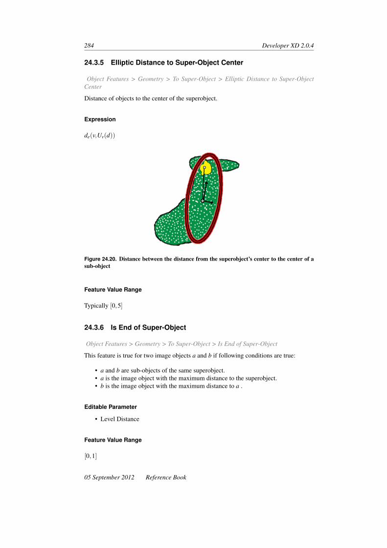
284 Developer XD 2.0.4
24.3.5 Elliptic Distance to Super-Object Center
Object Features > Geometry > To Super-Object > Elliptic Distance to Super-ObjectCenter
Distance of objects to the center of the superobject.
Expression
de(v,Uv(d))
Figure 24.20. Distance between the distance from the superobject’s center to the center of asub-object
Feature Value Range
Typically [0,5]
24.3.6 Is End of Super-Object
Object Features > Geometry > To Super-Object > Is End of Super-Object
This feature is true for two image objects a and b if following conditions are true:
• a and b are sub-objects of the same superobject.• a is the image object with the maximum distance to the superobject.• b is the image object with the maximum distance to a .
Editable Parameter
• Level Distance
Feature Value Range
[0,1]
05 September 2012 Reference Book

Object Features: Geometry 285
24.3.7 Is Center of Super-Object
Object Features > Geometry > To Super-Object > Is Center of Super-Object
This feature is true if the image object is the center of its superobject.
Editable Parameter
• Level Distance
Feature Value Range
[0,1]
24.3.8 Rel. X Position to Super-Object
Object Features > Geometry > To Super-Object Rel. X Position to Super-Object
This feature returns the relative x position of an image object with regard to its superob-ject, based on the centers of gravity of both objects.
Editable Parameters
• Level Distance – the upward distance of image object levels in the image objecthierarchy between the image object and the superobject.
Expression
∆x = xCG of current image object−xCG of superobject (where xCG is the center of gravity)
Feature Value Range
− scene width2
+scene width
2
24.3.9 Rel. Y Position to Super-Object
Object Features > Geometry > To Super-Object > Rel. Y Position to Super-Object
This feature returns the relative y position of an image object with regard to its superob-ject, based on the centers of gravity of both objects.
Editable Parameter
• Level Distance: Upward distance of image object levels in the image object hierar-chy between the image object and the superobject.
Reference Book 05 September 2012

286 Developer XD 2.0.4
Expression
∆y = yCG of current image object−yCG of superobject (where yCG is the center of gravity)
Feature Value Range
− scene height2
+scene height
2
24.4 Based on Polygons
Object Features > Geometry > Based on Polygons
The polygon features provided by Definiens Developer XD 2.0.4 are based on the vector-ization of the pixels that form an image object.
Figure 24.21. Raster image object (black area) with its polygon object (red lines) after vector-ization
24.4.1 Edges Longer Than
Object Features > Geometry > Based on Polygons > Edges Longer Than
Editable Parameters
• Minimum Length
24.4.2 Number of Right Angles With Edges Longer Than
Object Features > Geometry > Based on Polygons > Number of Right Angles with EdgesLonger Than
The number of right angles that have at least one side edge longer than a given threshold.
Editable Parameters
• Minimum length
05 September 2012 Reference Book

Object Features: Geometry 287
Figure 24.22. A polygon with one rectangular angle
24.4.3 Area (Excluding Inner Polygons)
Object Features > Geometry > Based on Polygons > Area (Excluding Inner Polygons)
The Area (Excluding Inner Polygons) feature calculates the area of a polygon based onGreen’s Theorem in a plane. In contrast to the Area (Including Inner Polygons) feature,the feature value does not include the areas of any existing inner polygons.
Parameters
• (xi,yi), i = 0, . . . ,n, with xo = xn and yo = yn as the given points• ai = xiyi+1− xi+1yi
Expression
12
n−1
∑i=0
ai
Figure 24.23. A polygon with an inner polygon that is not included in the feature value
Reference Book 05 September 2012

288 Developer XD 2.0.4
Feature Value Range
[0,scene size]
24.4.4 Area (Including Inner Polygons)
Object Features > Geometry > Based on Polygons > Area (Including Inner Polygons)
The Area (Excluding Inner Polygons) feature calculates the area of a polygon based onGreen’s Theorem in a plane. Different to the Area (Excluding Inner Polygons) feature,the feature value includes the areas of any existing inner polygons (for instance the singlepolygon formed in the center of a donut-shaped object).
Figure 24.24. A polygon with an inner polygon that is included in the feature value
24.4.5 Average Length of Edges (Polygon)
Object Features > Geometry > Based on Polygons > average Length of Edges (Polygon)
The average length of all edges in a polygon.
Parameters
• Xi is the length of edge i• n is the total number of edges
Expression
Average =
n
∑i=1
Xi
n
24.4.6 Compactness (Polygon)
Object Features > Geometry > Based on Polygons > Compactness (Polygon)
The ratio of the area of a polygon to the area of a circle with the same perimeter.
05 September 2012 Reference Book

Object Features: Geometry 289
Parameters
• Area• Perimeter
Expression
4×π×AreaPerimeter2
Feature Value Range
[0,1 for a circle]
24.4.7 Length of Longest Edge (Polygon)
Object Features > Geometry > Based on Polygons > Length of Longest Edge (Polygon)
The length of the longest edge of a polygon.
24.4.8 Number of Edges (Polygon)
Object Features > Geometry > Based on Polygons > Number of Edges (Polygon)
The number of edges of a polygon.
24.4.9 Number of Inner Objects (Polygon)
Object Features > Geometry > Based on Polygons > Number of Inner Objects (Polygon)
The number of inner polygons that are completely surrounded by a selected outer poly-gon.
24.4.10 Perimeter (Polygon)
Object Features > Geometry > Based on Polygons > Perimeter (Polygon)
The sum of the lengths of all the edges of a polygon.
24.4.11 Polygon Self-Intersection (Polygon)
Object Features > Geometry > Based on Polygons > Polygon Self-Intersection (Polygon)
The Polygon Self-Intersection (Polygon) feature allows the identification of a rare ar-rangement of image objects, leading to a polygon self-intersection when exported as apolygon vector file.
Reference Book 05 September 2012

290 Developer XD 2.0.4
This feature enables you to identify the affected image objects and take measures Toavoid this self-intersection. All image objects with a value of 1 will cause a polygonself-intersection when exported to a shapefile.
Figure 24.25. This type of image object leads to a self-intersection at the circled point
To avoid the self-intersection, the enclosed image object needs to be merged with theenclosing image object.
TIP: Use the Image Object Fusion algorithm to remove polygon intersec-tions. To do so, set the domain to all image objects with a value largerthan 0 for the polygon intersection feature. In the algorithm parameter, setthe Fitting Function Threshold to Polygon Self-Intersection (Polygon) fea-ture to zero and in the Weighted Sum group, set Target Value Factor to 1.This will merge all image objects with a value of 1 for the Polygon Self-Intersection (Polygon) feature, so that the resulting image object will notinclude a self-intersection.
Feature Value Range
[0,1]
24.4.12 Std. Dev. of Length of Edges (Polygon)
Object Features > Geometry > Based on Polygons > Stddev of Length of Edges (Polygon)
The Std. Dev. of Length of Edges (Polygon) feature measures how the lengths of edgesdeviate from their mean value.
Parameters
• xi is the length of edge i• X is the mean value of all lengths• n is the total number of edges
05 September 2012 Reference Book

Object Features: Geometry 291
Expression√√√√√ n
∑i=1
(xi− x)2
n
24.5 Based on Skeletons
Object Features > Geometry > Based on Skeletons
For the better understanding of the following descriptions, the skeleton is structured in amain line and subordinate branches. A node is a mid-point of the triangles created by theDelaunay triangulation.
24.5.1 Number of Segments of Order
Object Features > Geometry > Based on Skeletons > Number of Segments of Order
The number of line segments of branches of an object that are of a given order. Note thatonly segments that do not belong to a lower order are counted
Editable Parameter
• Branch order: The main line of the skeleton has the order 0.
Feature Value Range
[0,depending on shape of objects]
24.5.2 Number of Branches of Order
Object Features > Geometry > Based on Skeletons > Number of Branches of Order
The number of branches of an object that are of a given order.
Editable Parameter
• Branch order: The main line of the skeleton has the order 0
Feature Value Range
[0,depending on shape of objects]
Reference Book 05 September 2012

292 Developer XD 2.0.4
24.5.3 Average Length of Branches of Order
Object Features > Geometry > Based on Skeletons > average Length of Branches ofOrder
The average length of branches of an object that are of a given order. The length of thebranch of the selected order is measured from the intersect point of the whole branch andthe main line to the end of the branch.
Editable Parameter
• Branch order: The main line of the skeleton has the order 0.
Feature Value Range
[0,depending on shape of objects]
24.5.4 Number of Branches of Length
Object Features > Geometry > Based on Skeletons > Number of Branches of Length
The number of branches of an object that are of a special length up to a selected order.All ends of branches are counted up to the selected order.
Editable Parameter
• Branch order: The main line of the skeleton has the order 0.• Minimum length• Maximum length
Feature Value Range
[0; depending on shape of objects]
24.5.5 Average Branch Length
Object Features > Geometry > Based on Skeletons > Average Branch Length
The average length of all branches of an object.
Feature Value Range
[0,depending on shape of objects]
05 September 2012 Reference Book

Object Features: Geometry 293
24.5.6 Avrg. Area Represented by Segments
Object Features > Geometry > Based on Skeletons > Avrg. Area Represented by Seg-ments
The average area of all triangles created by a Delaunay triangulation.
Feature Value Range
[0,depending on shape of objects]
24.5.7 Curvature/Length (Only Main Line)
Object Features > Geometry > Based on Skeletons > Curvature/Length (only main line)
The length-to-curvature ratio of the main line of an object. The curvature is the sum ofall changes in direction of the main line. Changes in direction are expressed by the acuteangle a in which sections of the main line, built by the connection between the nodes,cross each other.
Figure 24.26. The main line (green) connects the mid-points of triagles (black and blue) cre-ated by a Delaunay triangulation of the objects’ shape (not depicted)
Feature Value Range
[0,depending on shape of objects]
24.5.8 Degree of Skeleton Branching
Object Features > Geometry > Based on Skeletons > Degree of Skeleton Branching
The highest order of branching in an object.
Feature Value Range
[0,depending on shape of objects]
Reference Book 05 September 2012

294 Developer XD 2.0.4
24.5.9 Length of Main Line (No Cycles)
Object Features > Geometry > Based on Skeletons > Length of Main Line (No Cycles)
The sum of all distances between the nodes of the main line of an object. If an objectcontains an island polygon – a polygon derived from the inner borders of an image object– it is ignored and the main line may cross it (no cycles). This is different to the Length ofMain Line (regarding cycles) feature where the main line goes around the island polygon.This feature does not visualize skeletons.
Feature Value Range
[0,depending on shape of objects]
24.5.10 Length of Main Line (Regarding Cycles)
Object Features > Geometry > Based on Skeletons > Length of Main Line (regardingcycles)
The sum of all distances between the nodes of the main line of an object. If an objectcontains an island polygon – a polygon derived from the inner borders of an image object– the main line is calculated so as not to cross it (Regarding Cycles). In contrast to theLength of Main Line (No Cycles) feature, the skeletons are visualized.
Feature Value Range
[0,depending on shape of objects]
24.5.11 Length/Width (Only Main Line)
Object Features > Geometry > Based on Skeletons >Length/Width (Only Main Line)
The length-to-width ratio of the main line of an object.
Feature Value Range
[0,depending on shape of objects]
24.5.12 Maximum Branch Length
Object Features > Geometry > Based on Skeletons > Maximum Branch Length
The length of the longest branch of an object. It is measured from the intersect point ofthe branch and the main line to the end of the branch.
05 September 2012 Reference Book

Object Features: Geometry 295
Feature Value Range
[0,depending on shape of objects]
24.5.13 Number of Segments
Object Features > Geometry > Based on Skeletons > Number of Segments
The number of all segments of the main line and the branches of an object.
Feature Value Range
[0,depending on shape of objects]
24.5.14 Stddev Curvature (Only Main Line)
Object Features > Geometry > Based on Skeletons > Stddev Curvature (Only Main Line)
The standard deviation of the curvature is the result of the standard deviation of thechanges in direction of the main line. Changes in direction are expressed by the acuteangle in which sections of the mainline, built by the connection between the nodes, crosseach other.
Feature Value Range
[0,depending on shape of objects]
24.5.15 Stddev of Area Represented by Segments
Object Features > Geometry > Based on Skeletons > Stddev. of Area Represented bySegments
The standard deviation of all triangles created by the Delaunay triangulation.
Feature Value Range
[0,depending on shape of objects]
24.5.16 Width (Only Main Line)
Object Features > Geometry > Based on Skeletons > Width (Only Main Line)
The width of an object based on the height of triangles created by a Delaunay triangula-tion. It is calculated by the average height h of all triangles crossed by the main line.
An exception is triangles where the height h does not cross one of the sides of the triangle.In this case, the nearest side s is used to define the height.
Reference Book 05 September 2012

296 Developer XD 2.0.4
Figure 24.27. Height h of an triangle that is crossed by the main line
Figure 24.28. Height of an triangle that is crossed by the main line. In this case the side sdefines the height
Feature Value Range
[0,depending on shape of objects]
05 September 2012 Reference Book
25 Object Features: Position
Object Features > Position
Position features refer to the position of an image object relative to the entire scene. Thesefeatures are of special interest when working with geographically referenced data, as animage object can be described by its geographic position. Position features refer to thepixel co-ordinate definition.
25.1 Distance
Object Features > Position > Distance
25.1.1 Distance to Line
Object Features > Position > Distance > Distance to Line
The distance between the center of gravity of a two-dimensional image object and a givenline. The line is defined manually by entering two points that are a part of this line. Notethat the line has neither a start nor an end.
Editable Parameters
To set, right-click the Distance to Line feature, select Edit Feature and adapt the co-ordinates of the two points:
• First Co-ordinate (X)• First Co-ordinate (Y )• Second Co-ordinate (X)• Second Co-ordinate (Y )
Feature Value Range
[0,∞]
297

298 Developer XD 2.0.4
Figure 25.1. Distance between an image object and a line
25.1.2 Distance to Scene Border
Object Features > Position > Distance > Distance to Scene Border
The distance of an image object slice (a 2D piece of the image object in a slice) to thenearest border of the scene within the current slice. (The Z-direction is ignored.)
Parameters
• min x is the minimum distance from the scene border at x -axis• max x is the maximum distance from the scene border at x -axis• min y is the minimum distance from the scene border at y -axis• max y is the maximum distance from the scene border at y -axis• (sx,sy) is the scene size
Expression
min{min x,sx−max x,min y,sy−max y}
Figure 25.2. Examples of the distance between an image object and the nearest scene border
Feature Value Range
[0,max sx−1,sy−1]
05 September 2012 Reference Book

Object Features: Position 299
25.1.3 T Distance to First Frame (Pxl)
Object Features > Position > Distance > T Distance to First Frame (Pxl)
The distance of an image object to the first frame of the scene.
25.1.4 T Distance to Last Frame
Object Features > Position > Distance > T Distance to Last Frame
The distance of an image object to the last frame of the scene.
25.1.5 X Distance to Scene Left Border
Object Features > Position > Distance > X Distance to Scene Left Border
Horizontal distance of an image object slice (a 2D piece of the image object in a slice) tothe left border of the scene within the current slice.
Parameters
• sx is the scene size at the x -axis• min x is the minimum distance from the scene border at x -axis
Expression
min(x,y)∈Pv
x
Figure 25.3. X-distance between the image object and the left border
Feature Value Range
[0,sx−1]
Reference Book 05 September 2012

300 Developer XD 2.0.4
25.1.6 X Distance to Scene Right Border
Object Features > Position > Distance > X Distance to Scene Right Border
Horizontal distance of an image object slice (a 2D piece of the image object in a slice) tothe right border of the scene within the current slice.
Parameters
• sx is the scene size at the x -axis• max x is the maximum distance from the scene border at x -axis
Expression
sx− max(x,y)∈Pv
x
Figure 25.4. X-distance to the image object right border
Feature Value Range
[0,sx−1]
25.1.7 Y Distance to Scene Bottom Border
Object Features > Position > Distance > Y Distance to Scene Bottom Border
Vertical distance of an image object slice (a 2D piece of the image object in a slice) to thebottom border of the scene within the current slice.
Parameters
• sy is the scene size• min y is the minimum distance from the scene border at y -axis
Expression
min(x,y)∈Pv
y
05 September 2012 Reference Book

Object Features: Position 301
Figure 25.5. Y-distance between the image object and the bottom border
Feature Value Range
[0,sy−1]
25.1.8 Y Distance to Scene Top Border
Object Features > Position > Distance > Y Distance to Scene Top Border
Vertical distance of an image object slice (a 2D piece of the image object in a slice) to thetop border of the scene within the current slice.
Parameters
• sy is the scene size• max y is the maximum distance from the scene border at y -axis
Expression
sy− max(x,y)∈Pv
y
Figure 25.6. Y-distance between the image object and the top border of the scene
Feature Value Range
[0,sy−1]
Reference Book 05 September 2012

302 Developer XD 2.0.4
25.1.9 Z Distance to First Slice (Pxl)
Object Features > Position > Distance > Z Distance to First Slice (Pxl)
Distance of an image object to the first slice of the scene.
25.1.10 Z Distance to Last Slice (Pxl)
Object Features > Position > Distance > Z Distance to Last Slice (Pxl)
Distance of an image object to the last slice of the scene.
25.2 Co-ordinate
Object Features > Position > Co-ordinate
25.2.1 Hilbert Index
Object Features > Position > Co-ordinate > Hilbert Index
Generates a Hilbert Curve1 within an object; for a given curve, the feature returns theposition on the Hilbert curve on which an image object lies.
Parameters
• Pxl – enter a value for the resolution of the grid in pixels
25.2.2 Is at Active Pixel
Object Features > Position > Co-ordinate > Is at Active Pixel
This feature returns 1 if the current active pixel is within the image object, otherwise 0.
25.2.3 Time (Pxl)
Object Features > Position > Co-ordinate > Time
T-position of the center of an image object. The calculation is based on the center ofgravity (geometric center) of the image object in the internal map.
Parameters
• tv is the t -center of an image object v• xv is the x -center of an image object v in an internal map with xv(map) = 1
#Pv×
∑(xmap,ymap)∈Pv xmap• sxframe is the extent in x of each slice and frame
1. en.wikipedia.org/wiki/Hilbert_curve
05 September 2012 Reference Book
Object Features: Position 303
Expression
tv = floor(
xv(map)sxframe
)
Feature Value Range
[0.5,number of frames in map−0.5]
25.2.4 Time Max (Pxl)
Object Features > Position > Co-ordinate > Time Max (Pxl)
Maximum t -position of an image object derived from its bounding box. The calculationis based on the maximum t -position of the image object in the internal map.
Parameters
• tmax(v) is the maximum t -position of an image object v• xmax(v,map) is the maximum x -position of an image object v in an internal map• sx f rame is the extent in x of each slice and frame
Expression
tv = floor(
xv(map)sxframe
)
Feature Value Range
[1,number of frames in map]
25.2.5 Time Min (Pxl)
Object Features > Position > Co-ordinate > Time Min (Pxl)
Minimum t -position of an image object derived from its bounding box. The calculationis based on the minimum t -position of the image object in the internal map.
Parameters
• tmin(v) is the minimum t -position of an image object v• xmin(v,map) is the minimum x -position of an image object t in an internal map• sxframe is the extent in x of each slice and frame
Reference Book 05 September 2012

304 Developer XD 2.0.4
Expression
tmin(v) = floor(
xmin(v,map)sxframe
)
Feature Value Range
[0.5,number of frames in map−1]
25.2.6 X Center
Object Features > Position > Co-ordinate > X Center
X-position of the center of an image object. The calculation is based on the center ofgravity (geometric center) of the image object in the internal map.
Parameters
• xv is the x -center of an image object v• xv(map) is the x -center of an image object v in an internal map with xv(map) =
1#Pv×∑(xmap,ymap)∈Pv xmap
• #Pv is the total number of pixels contained in Pv• (xmap,ymap) are the co-ordinates in an internal map• sxframe is the extent in x of each slice and frame
Expression
xv = xv(map)−floor(
xv(map)sxframe
)× sxframe
Feature Value Range
[scene extent in x,0.5]
25.2.7 X Max.
Object Features > Position > Co-ordinate > X Max
Maximum x -position of an image object derived from its bounding box. The calculationis based on the maximum x -position of the image object in the internal map.
Parameters
• xmax(v) is the minimum x -position of an image object v• xmax(v,map) is the maximum x -position of an image object t in an internal map• sxframe is the extent in x of each slice and frame
05 September 2012 Reference Book

Object Features: Position 305
Expression
xmax(v) = xmax(v,map)−floor(
xmax(map)sxframe
)× sxframe
Figure 25.7. Maximum value of the x-coordinate at the image object border
Feature Value Range
[1,scene extent in x]
25.2.8 X Min.
Object Features > Position > Co-ordinate > X Min
Minimum x-position of an image object derived from its bounding box. The calculationis based on the minimum x-position of the image object in the internal map.
Parameters
• xmin(v) is the minimum x -position of an image object v• xmin(v,map) is the minimum x -position of an image object v in an internal map• sxframe is the extent in x of each slice and frame
Expression
xmin(v) = xmin(v,map)−floor(
xmin(v,map)sxframe
)× sxframe
Figure 25.8. Minimum value of the x-coordinate at the image object border
Reference Book 05 September 2012

306 Developer XD 2.0.4
Feature Value Range
[0,scene extent in x−1]
25.2.9 Y Center
Object Features > Position > Co-ordinate > Y Center
Y-position of the center of an image object. The calculation is based on the center ofgravity (geometric center) of the image object in the internal map.
Parameters
• yv is the y -center of an image object v• yv(map) is the y -center of an image object v in an internal map with yv(map) =
1#Pv×∑(xmap,ymap)∈Pv ymap
• #Pv is the total number of pixels contained in Pv• (xmap,ymap) are the co-ordinates in an internal map• syslice is the extent in y of each slice and frame
Expression
yv = yv(map)−floor(
yv(map)syslice
)× syslice
Figure 25.9. Center of gravity of an image object
Feature Value Range
[0.5,scene extent in x−0.5]
25.2.10 Y Max.
Object Features > Position > Co-ordinate > Y Max
Maximum y-position of an image object derived from its bounding box. The calculationis based on the maximum y-position of the image object in the internal map.
05 September 2012 Reference Book

Object Features: Position 307
Parameters
• ymax(v) is the maximum y -position of an image object v• ymax(v,map) is the minimum y -position of an image object v in an internal map• syslice is the extent in y of each slice and frame
Expression
ymax(v) = ymax(v,map)−floor(
ymax(v,map)syslice
)× syslice
Figure 25.10. Maximum value of the y-coordinate at the image object border
Feature Value Range
[1,scene extent in y]
25.2.11 Y Min.
Object Features > Position > Co-ordinate > Y Min
Minimum y-position of an image object derived from its bounding box. The calculationis based on the minimum y-position of the image object in the internal map.
Parameters
• ymin(v) is the minimum y -position of an image object v• ymin(v,map) is the minimum y -position of an image object v in an internal map• syslice is the extent in y of each slice and frame
Expression
ymin(v) = ymin(v,map)−floor(
ymin(v,map)syslice
)× syslice
Feature Value Range
[0,scene extent in y−1]
Reference Book 05 September 2012

308 Developer XD 2.0.4
Figure 25.11. Minimum value of the y-coordinate at the image object border
25.2.12 Z Center
Object Features > Position > Co-ordinate > Z Center
Z -position of the center of an image object. The calculation is based on the center ofgravity (geometric center) of the image object in the internal map.
Parameters
• zv is the z -center of an image object v• yv(map) is the y -center of an image object v in an internal map with yv(map) =
1#Pv×∑(xmap,ymap)∈Pv ymap
• syslice is the extent in y of each slice and frame
Expression
zv = floor(
yv(map)syslice
)
Feature Value Range
[0.5,number of slices in map−0.5]
25.2.13 Z Max
Object Features > Position > Co-ordinate > Z Max
Maximum z -position of an image object derived from its bounding box. The calculationis based on the maximum z -position of the image object in the internal map.
Parameters
• zmax(v) is the maximum z -position of an image object v• ymax(v,map) is the minimum y -position of an image object v in an internal map• syslice is the extent in y of each slice and frame
05 September 2012 Reference Book

Object Features: Position 309
Expression
zmax(v) = floor(
ymax(v,map)syslice
)
Feature Value Range
[1,number of slices in map]
25.2.14 Z Min
Object Features > Position > Co-ordinate > Z Min
Minimum z -position of an image object derived from its bounding box. The calculationis based on the minimum z -position of the image object in the internal map.
Parameters
• zmin(v) is the maximum z -position of an image object v• ymin(v,map) is the minimum y -position of an image object v in an internal map• syslice is the extent in y of each slice and frame
Expression
zmin(v) = floor(
ymin(v,map)syslice
)
Feature Value Range
[0,number of slices in map−1]
25.3 Is Object in Region
Object Features > Position > Is Object in Region
The Is Object In Region feature checks if an image object is located in a given region. Ifthis is true, the feature value is 1 (= true), otherwise it is 0 (= false).
25.3.1 Editable Parameters
• Region
25.3.2 Feature Value Range
[0,1]
Reference Book 05 September 2012


26 Object Features: Texture
Object Features > Texture
Texture features are used to evaluate the texture of image objects and include featuresbased on an analysis of sub-objects helpful for evaluating highly textured data. In addi-tion, features based upon the gray level co-occurrence matrix after Haralick are available.Features are structured in the following groups:
• Texture concerning the spectral information of the sub-objects• Texture concerning the form of the sub-objects• Texture after Haralick based on the gray level co-occurrence matrix (GLCM),
which is a tabulation of how often different combinations of pixel gray levels occurin an image.
26.1 Layer Value Texture Based on Sub-objects
Object Features > Texture > Layer Value Texture Based on Sub-objects
Layer Value Texture Based on Sub-objects features refer to the spectral information pro-vided by the image layers. To refer to an image object level of sub-objects, you can editthe level distance.
26.1.1 Mean of Sub-objects: Std. Dev.
Object Features > Texture > Layer Value Texture Based on Sub-objects > Mean of Sub-objects: Stddev.
Standard deviation of the different layer mean values of the sub-objects. This featuremight appear very similar to the simple standard deviation computed from the single pixelvalues (layer values); however it can be more meaningful because – assuming an adequatesegmentation – the standard deviation is computed over homogeneous and meaningfulareas.
The smaller the sub-objects, the more the feature value approaches the standard deviationcalculated from single pixels.
Parameters
• Sv(d) is the sub-object of an image object v at distance d
311

312 Developer XD 2.0.4
• ck(u) is the mean intensity of layer k of an image object u• d is the image object level distance
Expression√√√√ 1#Sv(d)
(∑
uεSv(d)(ck(u))2− 1
#Sv (d) ∑uεSv(d)
ck(u) ∑uεSv(d)
ck(u)
)
Feature Value Range
[0,depending on bit depth of data]
Conditions
If Sv(d) = ∅ ∴ the expression is invalid.
26.1.2 Avrg. Mean Diff. to Neighbors of Sub-objects
Object Features > Texture > Layer Value Texture Based on Sub-objects > Avrg. MeanDiff. to Neighbors of Sub-objects
The contrast inside an image object expressed by the average mean difference of all itssub-objects for a specific layer.
This feature has a certain spatial reference, because a local contrast inside the area cov-ered by the image object is described. For each single sub-object the layer L mean differ-ence (absolute values) to adjacent sub-objects of the same superobject is calculated. Thefeature value is the mean value of the layer L mean differences.
Parameters
• Sv(d) is the sub-object of an image object v at distance d• δk(u) is the mean difference to neighbor of layer k of an image object u• d is the image obejct level distance
Expression
1#Sv(d)
εuεSv(d)∆k(u)
Feature Value Range
[0,depending on bit depth of data]
05 September 2012 Reference Book

Object Features: Texture 313
Conditions
If Sv(d) = ∅ ∴ the formula is invalid
26.2 Shape Texture Based on Sub-objects
Object Features > Texture > Shape Texture Based on Sub-objects
Shape Texture Based on Sub-objects features refer to the shape of sub-objects. To usethese features successfully we recommend an accurate segmentation of the map to ensuresub-objects are as meaningful as possible. To refer to an image object level of sub-objects,you can edit the level distance.
26.2.1 Area of Sub-objects: Mean
Object Features > Texture > Shape Texture Based on Sub-objects > Area of Sub-objects:Mean
Mean value of the areas of the sub-objects.
Parameters
• Sv(d) is the sub-object of an image object v at distance d• #Pu is the total number of pixels contained in u• d is the image object level distance
Expression
1#Sv(d) ∑
εSv(d)#Pu
Feature Value Range
[0,scene size]
Condition
If Sv(d) = ∅ ∴ the formula is invalid.
26.2.2 Area of Sub-objects: Std. Dev.
Object Features > Texture > Shape Texture Based on Sub-objects > Area of Sub-objects:Std Dev.
Standard deviation of the areas of the sub-objects.
Reference Book 05 September 2012

314 Developer XD 2.0.4
Parameters
• Sv(d) is the sub-object of an image object v at distance d• Pu is the total number of pixels contained in u• d is the image object level distance
Expression√√√√ 1#Sv(d)
(∑
uεSv(d)#P2
u −1
#Sv (d) ∑uεSv(d)
#Pu ∑uεSv(d)
#Pu
)
Feature Value Range
[0,scene size]
Condition
If Sv(d) = ∅ ∴ the formula is invalid.
26.2.3 Density of Sub-objects: Mean
Object Features > Texture > Shape Texture Based on Sub-objects > Density of Sub-objects: Mean
Mean value calculated from the densities of the sub-objects.
Parameters
• Sv(d) is the sub-object of an image object v at distance d• a(u) is the density of u• d is the image object level distance
Expression
1#Sv(d) ∑
uεSv(d)a(u)
Feature Value Range
[0,depending on image object shape]
Condition
If Sv(d) = ∅ ∴ the formula is invalid.
05 September 2012 Reference Book

Object Features: Texture 315
26.2.4 Density of Sub-objects: Std. Dev.
Object Features > Texture > Shape Texture Based on Sub-objects > Density of Sub-objects: Stddev.
Standard deviation calculated from the densities of the sub-objects.
Parameters
• Sv(d) is the sub-object of an image object v at distance d• a(u) is the density of u• d is the image object level distance
Expression√√√√ 1#Sv(d)
(∑
uεSv(d)a2(u)− 1
#Sv (d) ∑uεSv(d)
a(u) ∑uεSv(d)
a(u)
)
Feature Value Range
[0,depending on image object shape]
Condition
If Sv(d) = ∅ ∴ the formula is invalid.
26.2.5 Asymmetry of Sub-objects: Mean
Object Features > Texture > Shape Texture Based on Sub-objects > Asymmetry of Sub-objects: Mean
Mean value of the asymmetries of the sub-objects.
Parameters
• Sv(d) is the sub-object of an image object v at distance d• a(u) is the asymmetry of u• d is the image object level distance
Expression
1#Sv(d) ∑
uεSv(d)a(u)
Reference Book 05 September 2012
316 Developer XD 2.0.4
Feature Value Range
[0,depending on image object shape]
Condition
If Sv(d) = ∅ ∴ the formula is invalid.
26.2.6 Asymmetry of Sub-objects: Std. Dev.
Object Features > Texture > Shape Texture Based on Sub-objects > Asymmetry of Sub-objects: Stddev.
Standard deviation of the asymmetries of the sub-objects.
Parameters
• Sv(d) is the sub-object of an image object v at distance d• a(u) is the asymmetry of u• d is the image object level distance
Expression
1#Sv(d) ∑
uεSv(d)a(u)
Feature Value Range
[0,depending on image object shape]
Condition
If Sv(d) = ∅ ∴ the formula is invalid.
26.2.7 Direction of Sub-objects: Mean
Object Features > Texture > Shape Texture Based on Sub-objects > Direction of Sub-objects: Mean
The mean value of the directions of the sub-objects. In the computation, the directionsare weighted with the asymmetry of the respective sub-objects. The more asymmetric animage object, the more significant its main direction.
Before computing the actual feature value, the algorithm compares the variance of allsub-object main directions with the variance of the sub-object main directions, whereall directions between 90° and 180° are inverted. The set of sub-object main directionswhich has the lower variance is selected for the calculation of the main direction meanvalue, weighted by the sub-object asymmetries.
05 September 2012 Reference Book

Object Features: Texture 317
Figure 26.1. For calculation, the directions between 90° and 180° are inverted, which meansthe direction is reduced by 180°
Parameters
• Sv(d) is the sub-object of an image object v at distance d• a(u) is the main direction of u• d is the image object level distance
Expression
1#Sv(d) ∑
uεSv(d)a(u)
Feature Value Range
[0◦,180◦]
Condition
If Sv(d) = ∅ ∴ the formula is invalid.
26.2.8 Direction of Sub-objects: Std. Dev.
Object Features > Texture > Shape Texture Based on Sub-objects > Direction of Sub-objects: Stddev
Standard deviation of the directions of the sub-objects. Similar to Direction of Sub-objects: Mean feature, the sub-object main directions are weighted by the asymmetries ofthe respective sub-objects. The set of sub-object main directions from which the standarddeviation is calculated is determined in the same way.
26.3 Texture After Haralick
Object Features > Texture > Texture After Haralick
Reference Book 05 September 2012

318 Developer XD 2.0.4
The gray level co-occurrence matrix (GLCM) is a tabulation of how often different com-binations of pixel gray levels occur in a scene. A different co-occurrence matrix exists foreach spatial relationship. To receive directional invariance, the sum of all four directions(0°, 45°, 90°, 135°) are calculated before texture calculation. An angle of 0° representsthe vertical direction, an angle of 90° the horizontal direction. In Definiens software, tex-ture after Haralick is calculated for all pixels of an image object. To reduce border effects,pixels bordering the image object directly (surrounding pixels with a distance of 1) areadditionally taken into account.
The normalized GLCM is symmetrical. The diagonal elements represent pixel pairs withno gray level difference. Cells, which are one cell away from the diagonal, represent pixelpairs with a difference of only one gray level. Similarly, values in cells that are two pixelsaway from the diagonal, show how many pixels have two gray levels and so forth. Themore distant to the diagonal, the greater the difference between the pixels’ gray levels is.Summing-up the values of these parallel diagonals, gives the probability for each pixel tobe 0, 1, 2 or 3 etc. different from its neighbor pixels.
Another approach to measure texture is to use a gray-level difference vector (GLDV)instead of the GLCM. The GLDV is the sum of the diagonals of the GLCM. It countsthe occurrence of references to the neighbor pixels’ absolute differences. In Definienssoftware the GLCM and GLDV are calculated based on the pixels of an object. They arecomputed for each input layer. Within each Texture after Haralick feature you have thechoice of either one of the above directions or of all directions.
The calculation of Texture after Haralick is independent of the image data’s bit-depth.The dynamic range is interpolated to 8 bit before evaluating the co-occurrence. However,
05 September 2012 Reference Book

Object Features: Texture 319
if 8 bit data is used directly the results will be most reliable. When using data of higherdynamic than 8 bit, the mean and standard deviation of the values is calculated. Assuminga Gaussian distribution of the values, a value greater than 95% is inbetween the interval,which is subdivided into 255 equal sub-intervals to obtain an 8-bit representation.
x−3×σ < x < x+3×σ
The result of any texture after Haralick analysis is dependent upon the direction of theanalysis, whether it is All Directions, Direction 0°, Direction 45°, Direction 90° or Di-rection 135°. In addition, each feature is calculated based upon the gray values of oneselectable layer.
The calculation of any Haralick texture feature is very processor intensive because of thecalculation of the GLCM; as a result, performance may suffer.
26.3.1 Calculation of GLCM
Image object pixels are scanned and put into a 256 x 256 matrix, with pixel value andneighboring pixel value as co-ordinates. The value of the matrix is a normalized numberof pair occurrences (number of occurrences ÷ number of all pairs). So GLCM matrixvalues are always within the range [0,1] . The pixel value is either the pixel value of aparticular layer or the mean value of all layers (depending on the Haralick feature chosen).The neighboring pixel calculation depends upon the feature angle:
• 0° – (x;y−1) and (x;y+1)• 45° – (x−1,y−1) and (x+1,y+1)• 90° – (x−1;y) and (x+1;y)• 135° – (x−1,y+1) and (x+1,y−1)• All dir – all neighbor pixels described above.
The actual Haralick feature is calculated using the GLCM matrix and algorithm of aparticular feature. For example, the contrast feature is calculated using the formulae:
• for (int i=0; i<mtrx.Rows(); i++)• for (int j=0; j<mtrx.Cols(); j++)• ctrst += mtrx[i][j] * ((i-j)*(i-j)).
TIP: For each Haralick texture feature there is a performance optimizedversion labeled quick 8/11. The performance optimization works only ondata with a bit depth of 8 bit or 11-bit. Hence the label quick 8/11. Use theperformance optimized version whenever you work with 8- or 11-bit data.For 16 bit data, use the conventional Haralick feature.
26.3.2 Parameters
• i is the row number• j is the column number• Vi, j is the value in the cell i, j of the matrix• Pi, j is the normalized value in the cell i, j• N is the number of rows or columns
Reference Book 05 September 2012

320 Developer XD 2.0.4
26.3.3 Expression
Every GLCM is normalized according to the following operation:
Pi, j =Vi, j
N−1
∑i, j=0
Vi, j
26.3.4 References
Haralick RM, Shanmugan K and Dinstein I (1973). Textural Features for Image Classi-fication. IEEE Transactions on Systems, Man and Cybernetics. Vol SMC-3, No. 6 pp.610–621
Haralick RM (1979). Statistical and Structural Approaches to Texture. Proceedings ofthe IEEE. Vol. 67, No. 5, pp. 786–804
Conner RW and Harlow CA (1980). A Theoretical Comparison of Texture Algorithms.IEEE Transactions on Pattern Analysis and Machine Intelligence. Vol PAMI-2, No. 3.
26.3.5 GLCM Homogeneity
Object Features > Texture > Texture After Haralick > GLCM Homogeneity
If the image is locally homogeneous, the value is high if GLCM concentrates along thediagonal. Homogeneity weights the values by the inverse of the contrast weight withweights, decreasing exponentially according to their distance to the diagonal.
Parameters
• i is the row number• j is the column number• Pi, j is the normalized value in the cell i, j• N is the number of rows or columns
Expression
N−1
∑i, j=0
Pi, j
1+(i− j)2
Feature Value Range
[0,1]
05 September 2012 Reference Book

Object Features: Texture 321
26.3.6 GLCM Contrast
Object Features > Texture > Texture After Haralick > GLCM Contrast
Contrast is the opposite of homogeneity. It is a measure of the amount of local variationin the image. It increases exponentially as i− j increases.
Parameters
• i is the row number• j is the column number• Pi, j is the normalized value in the cell i, j• N is the number of rows or columns
Expression
N−1
∑i, j=0
Pi, j(i− j)2
Feature Value Range
[0,65025]
26.3.7 GLCM Dissimilarity
Object Features > Texture > Texture After Haralick > GLCM dissimilarity
Similar to contrast, but increases linearly. High if the local region has a high contrast.
Parameters
• i is the row number• j is the column number• Pi, j is the normalized value in the cell i, j• N is the number of rows or columns
Expression
N−1
∑i, j=0
Pi, j |i− j|
Feature Value Range
[0,255]
Reference Book 05 September 2012
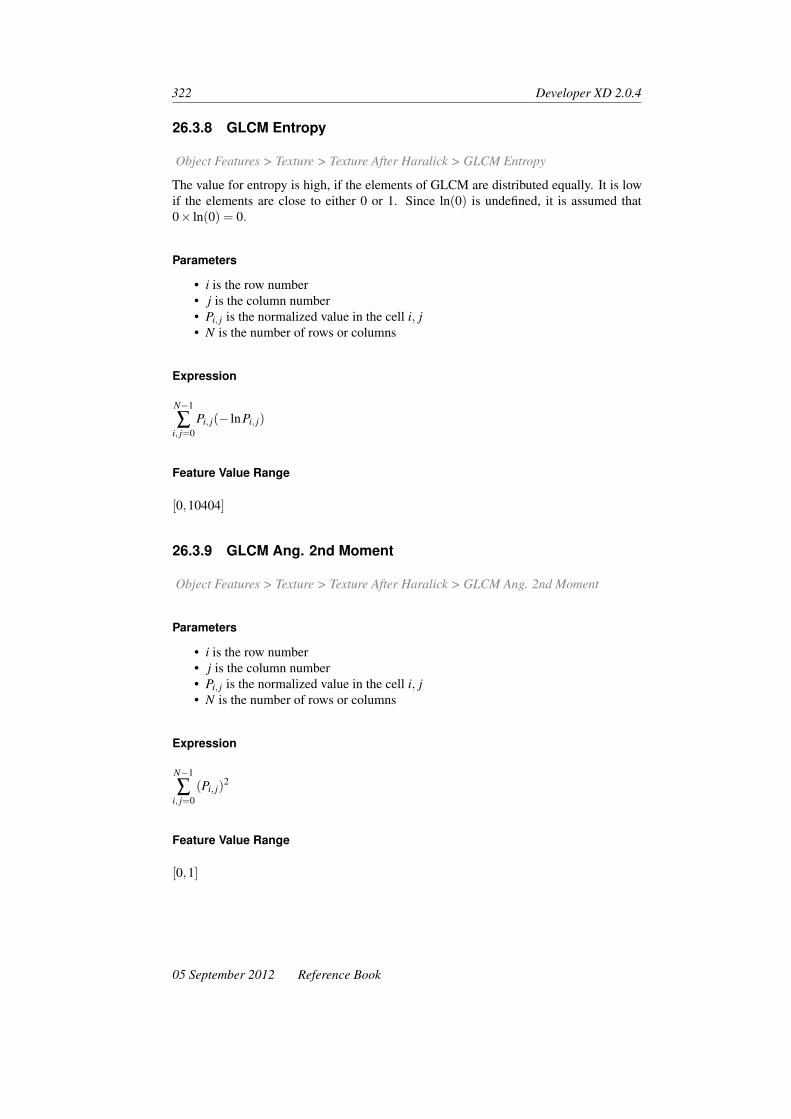
322 Developer XD 2.0.4
26.3.8 GLCM Entropy
Object Features > Texture > Texture After Haralick > GLCM Entropy
The value for entropy is high, if the elements of GLCM are distributed equally. It is lowif the elements are close to either 0 or 1. Since ln(0) is undefined, it is assumed that0× ln(0) = 0.
Parameters
• i is the row number• j is the column number• Pi, j is the normalized value in the cell i, j• N is the number of rows or columns
Expression
N−1
∑i, j=0
Pi, j(− lnPi, j)
Feature Value Range
[0,10404]
26.3.9 GLCM Ang. 2nd Moment
Object Features > Texture > Texture After Haralick > GLCM Ang. 2nd Moment
Parameters
• i is the row number• j is the column number• Pi, j is the normalized value in the cell i, j• N is the number of rows or columns
Expression
N−1
∑i, j=0
(Pi, j)2
Feature Value Range
[0,1]
05 September 2012 Reference Book

Object Features: Texture 323
26.3.10 GLCM Mean
Object Features > Texture > Texture After Haralick > GLCM Mean
The GLCM mean is the average expressed in terms of the GLCM. The pixel value is notweighted by its frequency of occurrence itself, but by the frequency of its occurrence incombination with a certain neighbor pixel value.
Parameters
• i is the row number• j is the column number• Pi, j is the normalized value in the cell i, j• N is the number of rows or columns
Expression
µi, j =
N−1
∑i, j=0
Pi, j
N2
Feature Value Range
[0,255]
26.3.11 GLCM Std. Dev.
Object Features > Texture > Texture After Haralick > GLCM Std Dev
GLCM standard deviation uses the GLCM, therefore it deals specifically with the combi-nations of reference and neighbor pixels. Thus, it is not the same as the simple standarddeviation of gray levels in the original image.
Calculating the standard deviation using i or j gives the same result, since the GLCM issymmetrical.
Standard deviation is a measure of the dispersion of values around the mean. It is similarto contrast or dissimilarity.
Parameters
• i is the row number• j is the column number• Pi, j is the normalized value in the cell i, j• N is the number of rows or columns• µi, j is the GLCM mean
Reference Book 05 September 2012

324 Developer XD 2.0.4
Expression
σ2i, j =
N−1
∑i, j=0
Pi, j(i, j−µi, j)
Standard Deviation
σ =√
σ2i, j
Feature Value Range
[0,255]
26.3.12 GLCM Correlation
Object Features > Texture > Texture After Haralick > GLCM Correlation
Measures the linear dependency of gray levels of neighboring pixels.
Parameters
• i is the row number• j is the column number• Pi, j is the normalized value in the cell i, j• N is the number of rows or columns• µi, j is the GLCM mean• σi, j is the GLCM standard deviation
Expression
N−1
∑i, j=0
Pi, j
(i,µi)( j−µ j)√(σ2
i )(σ2i )
Feature Value Range
[0,1]
26.3.13 GLDV Angular 2nd Moment
Object Features > Texture > Texture After Haralick > GLDV Ang. 2nd Moment
Similar to GLCM Angular Second Moment: it measures the local homogeneity. Thevalue is high if some elements are large and the remaining ones are small.
05 September 2012 Reference Book

Object Features: Texture 325
Parameters
• N is the number of rows or columns• Vk is the image object level, k = 1, . . .n
Expression
N−1
∑k=0
V 2k
Feature Value Range
[0,1]
26.3.14 GLDV Entropy
Object Features > Texture > Texture After Haralick > GLDV Entropy
The values are high if all elements have similar values. It is the opposite of GLDVAngular Second Moment.
Parameters
• i is the row number• j is the column number• Pi, j is the normalized value in the cell i, j• N is the number of rows or columns• Vk is the image object level, k = 1, . . .n
Expression
Since ln(0) is undefined, it is assumed that 0× ln(0) = 0.
N−1
∑k=0
Vk(−lnVk)
Feature Value Range
[0,10404]
26.3.15 GLDV Mean
Object Features > Texture > Texture After Haralick > GLDV Mean
The mean is mathematically equivalent to GLCM Dissimilarity on page 321. It is onlyleft here for compatibility reasons.
Reference Book 05 September 2012

326 Developer XD 2.0.4
Parameters
• N is the number of rows or columns• Vk is the image object level, k = 1, . . .n
Expression
N−1
∑k=0
k(Vk)
Feature Value Range
[0,255]
26.3.16 GLDV Contrast
Object Features > Texture > Texture After Haralick > GLDV Contrast
It is mathematically equivalent to the GLCM Contrast measure, described previously. Itis still included for compatibility reasons.
Parameters
• N is the number of rows or columns• Vk is the image object level, k = 1, . . .n
Expression
N−1
∑k=0
Vkk2
Feature Value Range
[0,65025]
26.3.17 GLCM/GLDV . . . (Quick 8/11)
Object Features > Texture > Texture After Haralick GLCM/GLDV [quick 8/11]
For each Haralick texture feature there is a performance optimized version with a ‘quick8/11’ suffix.
They are labeled ‘quick 8/11’ because the performance optimization works only on datawith a bit depth of 8 or 11-bits. Use the performance optimized version whenever youwork with 8- or 11-bit data; for 16 bit data, use the conventional Haralick feature.
05 September 2012 Reference Book

27 Object Features: Variables
Object Features > Variables
Object Variables are local variables. In contrast to scene variables they store values foreach individual image object. Think of it as each image object having its own version ofthe variable. There is one instance per image object in a project.
27.1 [Object Variable]
Object Features > Variables > Object Variable
If existing, all object variables are listed in the feature tree.
You can define a new object variable by clicking on Create new Object Variable to storeinterim values for each individual image object.
27.1.1 Editable Parameters
• Name• Value: Insert an initial value for the variable.• Choose whether the new variable is numeric (Double) or textual (String)• Shared: Select if you want to share the new variable among different rule sets
327


28 Object Features: Hierarchy
Object Features > Hierarchy
Hierarchy features provide information about the embedding of an image object withinthe image object hierarchy.
28.1 Level
Object Features > Hierarchy > Level
Returns the level object associated with an image object.
28.2 Level Number
Object Features > Hierarchy > Level Number
The number of the image object level an image object is situated in.
This feature is helpful when performing classifications on different image object levels todefine which class description is valid for which image object level.
28.2.1 Parameters
• Uv(d) are superobjects of an image object v at distance d
28.2.2 Expression
mind
Uv(d) = 0
28.2.3 Feature Value Range
[1,number of image object levels]
28.2.4 Conditions
This feature requires more than one image object level.
329

330 Developer XD 2.0.4
28.3 Number of Higher Levels
Object Features > Hierarchy > Number of Higher Levels
28.3.1 Parameters
• d is the distance between neighbors• Sv(d) are sub-objects of an image object v at a distance d
28.3.2 Expression(mind
Sv(d) = ∅)−1
28.3.3 Feature Value Range
[1,number of image object levels−1]
28.4 Number of Neighbors
Object Features > Hierarchy > Number of Neighbors
The number of the direct neighbors of an image object (in other words, neighbors withwhich it has a common border) on the same image object level in the image object hierar-chy.
28.4.1 Parameters
• Nv(d) are neighbors of an image object v at a distance d
28.4.2 Expression
#Nv(d)
28.4.3 Feature Value Range
[0,number of pixels of entire scene]
28.5 Number of Sub-Objects
Object Features > Hierarchy > Number of Sub-objects
Concerning an image object, the number of sub-objects that are located on the next lowerimage object level in the image object hierarchy.
05 September 2012 Reference Book

Object Features: Hierarchy 331
28.5.1 Parameters
• Sv(d) are sub-objects of an image object v at a distance d
28.5.2 Expression
#Sv(d)
28.5.3 Feature Value Range
[0,number of pixels of entire scene]
28.6 Number of Sublevels
Object Features > Hierarchy > Number of Sublevels
The number of image object levels situated below a given image object.
28.6.1 Parameters
• d is the distance between neighbors• Uv(d) are superobjects of an image object v at a distance d
28.6.2 Expression(mind
Uv(d) = ∅)−1
28.6.3 Feature Value Range
[1,number of image object levels−1]
Reference Book 05 September 2012

29 Object Features: ThematicAttributes
Object Features > Thematic Attributes
Thematic attribute features are used to describe an image object using information pro-vided by thematic layers. If your scene contains a thematic layer, its thematic object’sproperties, can be used to create thematic attribute features, which can be used for de-veloping ruleware. Depending on the attributes of the thematic layer, a large range ofdifferent features becomes available.
29.1 Number of Overlapping Thematic Objects
Object Features > Hierarchy > Number of Overlapping Thematic Objects
The number of thematic objects that an image object overlaps with. The scene contains athematic layer, otherwise the feature value is 0.
29.1.1 Editable Parameter
• Thematic Layer
29.1.2 Feature Value Range
[0,number of thematic objects]
29.2 Thematic Objects Attribute
Object Features > Hierarchy > [Thematic Objects Attribute]
If existing, Thematic Objects Attribute features referring to a thematic layer are listed inthe feature tree. Preconditions:
• The scene includes a thematic layer, otherwise the feature value is 0.• Available only for image objects that overlap with one thematic object, otherwise
the feature value is undefined.
333

334 Developer XD 2.0.4
29.2.1 Editable Parameters
• Thematic Layer• Thematic Layer Attribute
05 September 2012 Reference Book

30 Class-Related Features
Class-related features depend on image object features and refer to the class assigned otimage objects situated at any location in the image object hierarchy.
This location is specified for superobjects and sub-objects by the level distance definingthe vertical distance in the image object hierarchy. For neighbor image objects the lo-cation is specified by the spatial distance defining the horizontal distance in the imageobject hierarchy. These feature distances can be edited.
Class-related features are global features because they are not related to individual imageobjects. Class-Related Features are grouped as follows:
• Customized class-related features refer to class-related features. They are availableafter they have been created.
• Relations to neighbor objects features are used to describe an image object by itsrelationships to other image objects of a given class on the same image object level.
• Relations to Sub-objects features describe an image object by its relationships toother image objects of a given class on a lower image object level in the imageobject hierarchy. You can use these features to evaluate sub-scale information be-cause the resolution of image objects increases the lower you move in the imageobject hierarchy.
• Relations to Superobjects features describe an image object by its relations to otherimage objects of a given class on a higher image object level in the image objecthierarchy. You can use these features to evaluate super-scale information becausethe resolution of image objects decreases the higher you move in the image objecthierarchy.
• Relations to Classification features are used to find out about the current or poten-tial classification of an image object.
30.1 Relations to Neighbor Objects
Class-Related Features > Relations to Neighbor Objects
Relations to neighbor objects features are used to describe an image object by its relation-ships to other image objects of a given class on the same image object level.
30.1.1 Existence of
Class-Related Features > Relations to Neighbor Objects > Existence Of
335

336 Developer XD 2.0.4
Existence of an image object assigned to a defined class in a certain perimeter (in pixels)around the image object concerned. If an image object of the defined classification isfound within the perimeter, the feature value is 1 (= true), otherwise it would be 0 (= false).The radius defining the perimeter can be determined by editing the feature distance.
Expression
0 if Nv(d,m) = ∅ , 1 if Nv(d,m) 6= ∅
Feature Value Range
[0,1]
30.1.2 Number Of
Class-Related Features > Relations to Neighbor Objects > Number Of
Number of objects belonging to the selected class in a certain distance (in pixels) aroundthe image object.
Parameters
• v is the image object• d is the distance between neighbors• m is a class containing image objects
Expression
#Nv(d,m)
Feature Value Range
[0,∞]
30.1.3 Border To
Class-Related Features > Relations to Neighbor Objects > Border To
The absolute border of an image object shared with neighboring objects of a definedclassification. If you use geo-referenced data, the feature value is the real border toimage objects of a defined class; otherwise it is the number of pixel edges shared with theadjacent image objects, as by default the pixel edge-length is 1.
Parameters
• b(v,u) is the length of common border between v and u• Nv(d) are neighbors to an image object v at a distance d
05 September 2012 Reference Book

Class-Related Features 337
Expression
∑u∈Nv(d,m)
b(v,u)
Figure 30.1. The absolute border between unclassified and classified image objects
Feature Value Range
[0,∞]
30.1.4 Rel. Border to
Class-Related Features > Relations to Neighbor Objects > Rel. Border To
The feature Rel. Border To determines the relative border length an object shares withthe image border. It describes the ratio of the shared border length of an image object(with a neighboring image object assigned to a defined class) to the total border length. Ifthe relative border of an image object to image objects of a certain class is 1, the imageobject is totally embedded in them.
If the relative border is 0.5 then the image object is surrounded by half of its border. Therelative border length can only be expressed in pixels.
Parameters
• b(v,u) is the length of common border between v and u• Nv(d) are neighbors to an image object v at a distance d• bv is the image object border length
Expression
∑u∈Nv(d,m)
b(v,u)
bv
Feature Value Range
[0,1]
Reference Book 05 September 2012

338 Developer XD 2.0.4
Figure 30.2. Relative border between neighbors
Conditions
If the relative border is 0 then the class m does not exist. If the relative border is 1 thenthe object v is completely surrounded by class m
30.1.5 Rel. Area of
Class-Related Features > Relations to Neighbor Objects > Rel. Area Of
The area covered by image objects of a selected class, found within a user-defined circulararea around the selected image object, divided by the total area of image objects insidethis area.
Editable Parameters
• Class• Feature Distance: Radius (from the selected image object) of the area in pixels.
Parameters
• Nv(d) are neighbors to an image object v at a distance d• #Pu is total number of pixels contained in Pu
Expression
∑u∈Nv(d,m)
#Pu
∑u∈Nv(d)
#Pu
Feature Value Range
[0,1]
05 September 2012 Reference Book

Class-Related Features 339
Conditions
If the relative border is 0 then the class m does not exist. If the relative border is 1 thenthe object v is completely surrounded by class m
30.1.6 Distance to
Class-Related Features > Relations to Neighbor Objects > Distance To
The distance (in pixels) of the image object’s center concerned to the closest image ob-ject’s center assigned to a defined class. The image objects on the line between the imageobjects’ centers have to be of the defined class.
Parameters
• d(v,u) is the distance between v and u• Vi(m) is the image object level of a class m• bv is the image object border length
Expression
minu∈Vi(m)
d(v,u)
Figure 30.3. Distance between the centers of neighbors
Feature Value Range
[0,∞]
30.1.7 Mean Diff. to
Class-Related Features > Relations to Neighbor Objects > Mean Diff. To
The mean difference of the layer L mean value of the image object concerned to the layerL mean value of all image objects assigned to a defined class.
Reference Book 05 September 2012

340 Developer XD 2.0.4
Parameters
• v is the image object• Nvm is a neighbors to an image object v of a class m
Expression
∆(v,Nv(m))
Feature Value Range
[0,∞]
30.2 Relations to Sub-Objects
Class-Related Features > Relations to Sub Objects
Relations to sub-objects features describe an image object by its relationships to otherimage objects of a given class on a lower image object level in the image object hierarchy.You can use these features to evaluate sub-scale information because the resolution ofimage objects increases the lower you move in the image object hierarchy.
30.2.1 Existence Of
Class-Related Features > Relations to Sub Objects > Existence Of
The Existence Of feature checks if there is at least one sub-object assigned to a definedclass. If there is one, the feature value is 1 (= true), otherwise the feature value is 0 (=false).
Parameters
• v is the image object• d is the distance between neighbors• m is a class containing image objects
Expression
0 if Sv(d,m) = ∅ , 1 if Sv(d,m) 6= ∅
Feature Value Range
[0,1]
05 September 2012 Reference Book

Class-Related Features 341
30.2.2 Number of
Class-Related Features > Relations to Sub Objects > Number Of
The number of sub-objects assigned to a defined class.
Parameters
• v is the image object• d is the distance between neighbors• m is a class containing image objects
Expression
#Sv(d,m)
Feature Value Range
[0,∞]
30.2.3 Area of
Class-Related Features > Relations to Sub Objects > Area Of
The absolute area covered by sub-objects assigned to a defined class. If your data aregeo-referenced, the feature value represents the real area.
Parameters
• d is the distance• m is the class• M is a sub-object in class m
Expression
∑MESv(d,m)
#PM
Feature Value Range
[0,∞]
30.2.4 Rel. Area of
Class-Related Features > Relations to Sub Objects > Rel. Area Of
Area covered by sub-objects assigned to a given class divided by the total area of theimage object concerned.
Reference Book 05 September 2012

342 Developer XD 2.0.4
Editable Parameters
• Class• Image object level Distance: Downward distance of image object levels in the
image object hierarchy between the image object and the sub-object.
Parameters
• d is the image object level distance• m is the class• M is a sub-object in class m
Expression
∑MESv(d,m)
#PM
#Pv
Feature Value Range
[0,1]
30.2.5 Clark Aggregation Index
Class-Related Features > Relations to Sub Objects > Clark Aggregation Index
For a superobject the Clark aggregation index gives evidence about the spatial distributionof its sub-objects of a certain class.
Parameters
• D(x) is the mean spatial distance to next neighbor of the sub-objects of the class x• N(x) is the number of sub-objects of class x• A is the number of pixels of the superobject (Area)• Obs_mean_dist is the observed mean distance of sub objects to their spatial nearest
neighbor with Obs_mean_dist = ∑(D(x))N(x)
• Exp_mean_dist is the expected mean distance of sub objects to their spatial nearestneighbor with Exp_mean_dist = 1
2√
N(x)A
• CAI is the Clark aggregation index
Expression
CAI =Obs_Mean_DistanceExp_Mean_Distance
05 September 2012 Reference Book
Class-Related Features 343
Feature Value Range
[0,2.149]
• 0 – heavily clumped sub-objects• 1 – homogeneous spatial distribution of sub-objects• 2.149 – hexagonal distribution (edges of a honeycomb) of the sub-objects
30.3 Relations to Superobjects
Class-Related Features > Relations to Super Objects
Relations to superobjects features describe an image object by its relations to other imageobjects of a given class on a higher image object level in the image object hierarchy. Youcan use these features to evaluate super-scale information because the resolution of imageobjects decreases the higher you move in the image object hierarchy.
30.3.1 Existence of
Class-Related Features > Relations to Super Objects > Existence of
Checks if the superobject is assigned to a defined class. If this is true, the feature value is1, otherwise 0.
Parameters
• v is the image object• d is the distance to superobjects• m is the a class containing image objects
Expression
0 if Uv(d,m) = ∅ , 1 if Uv(d,m) 6= ∅
Feature Value Range
[0,1]
30.4 Relations to Classification
Class-Related Features > Relations to Classification
Relations to classification features are used to find out about the current or potentialclassification of an image object.
Reference Book 05 September 2012

344 Developer XD 2.0.4
30.4.1 Membership to
Class-Related Features > Relations to Classification > Membership to
In some cases it is important to incorporate the membership value to different classes inone class. This function allows explicit addressing of the membership values to differentclasses. If the membership value is below the assignment threshold, this value turns to 0.
Parameters
• v is the image object• m is the a class containing image objects• ϕ(v,m) stored membership value of an image object v to a class m
Expression
ϕ(v,m)
Feature Value Range
[0,1]
30.4.2 Assigned Class
Class-Related Features > Relations to Classification > Assigned Class
Returns the class associated with an image object.
30.4.3 Classified as
Class-Related Features > Relations to Classification > Classified As
The idea of this feature is to enable the user to refer to the classification of an imageobject without regard to the membership value. It can be used to freeze a classification.
Parameters
• v is the image object• m is a class containing image objects
Expression
m(v)
Feature Value Range
[0,1]
05 September 2012 Reference Book

Class-Related Features 345
30.4.4 Classification Value of
Class-Related Features > Relations to Classification > Classification Value Of
This feature Classification value of allows you to explicitly address the membership val-ues to all classes. As opposed to the feature Membership to it is possible to apply allmembership values to all classes without restrictions.
Parameters
• v is the image object• m is the a class containing image objects• ϕ(v,m) is a fuzzy membership value of an image object v to a class m
Expression
ϕ(v,m)
Feature Value Range
[0,1]
30.4.5 Class Name
Class-Related Features > Relations to Classification > Class Name
The Class name feature returns the name of the class (or superclass) of an image object(or its superobject).
Parameters
Distance in class hierarchy specifies the number of hierarchical levels when navigatingfrom class to superclass. Using a distance of 0 the class name is returned, a distance of1 will return the superclass name and so on. Distance in image object hierarchy specifiesthe number of hierarchical levels when navigating from object to superobject. Using adistance of 0 the class of the image object is used as a starting point for the navigation inthe class hierarchy, a distance of 1 will start at the class of the superobject.
30.4.6 Class Color
Class-Related Features > Relations to Classification > Class Color
The Class color feature returns either the red, green or blue color component of the class(or superclass) of an image object (or its superobject).
Reference Book 05 September 2012

346 Developer XD 2.0.4
Parameters
Color component is red, green or blue.
Distance in class hierarchy specifies the number of hierarchical levels when navigatingfrom class to superclass. Using a distance of 0 the class name is returned, a distance of 1will return the superclass name and so on.
Distance in image object hierarchy specifies the number of hierarchical levels when nav-igating from object to superobject. Using a distance of 0 the class of the image object isused as a starting point for the navigation in the class hierarchy, a distance of 1 will startat the class of the superobject.
05 September 2012 Reference Book

31 Linked Object Features
Linked Object features are calculated by evaluating linked objects themselves.
31.1 Linked Object Count
Linked Object Features > Linked Objects Count
The number of objects connected by object links fulfilling the filter parameters.
This feature traverses all links complying with the filter parameters and counts all objectsvisited while traversing. You can use this feature to measure the number of objects in alinked structure.
31.1.1 Editable Parameters
• Link Class Filter: Select the classes that contain the links to be counted• Link Direction: Filter on the link direction:
– All: Count all links, independent of link direction.– In: Count only inbound links.– Out: Count only outbound links.
• Max. Distance: Maximum number of links in a path that will be taken into account.This parameter lets you limit the counting to an object’s local neighborhood. Use0 for objects one link away, 1 for objects two links away and 999999 to count alllinked objects.
31.2 Linked Objects Statistics
Linked Object Features > Linked Objects Statistics
This feature allows computing a variety of statistical values for a group of linked objects.
31.2.1 Editable Parameters
• Operation: Select the type of statistical operation to be performed:– Sum: Compute the sum of the selected feature for all linked objects– Mean: Compute the mean value of the selected feature for all linked objects
347

348 Developer XD 2.0.4
Figure 31.1. Example of a linked objects domain of outgoing direction within a maximumdistance of 3
– Std Dev: Compute the standard deviation of the selected feature for all linkedobjects
– Min: Returns the minimum value of the selected feature for all linked objects– Max: Returns the maximum value of the selected feature for all linked objects– Is Min: Returns 1 if the image object is the minimum for the selected feature
for all linked objects– Is Max: Returns 1 if the image object is the maximum for the selected feature
for all linked objects– Count: Counts the linked objects. Ignores the selected feature
• Feature: Select the image object feature that will be used for the statistical opera-tion.
• Link Class Filter: Select the classes that contain the links to be counted• Candidate Condition: Select the condition the linked objects must fulfill to be
included in the statistical computation• Link Direction: Filter on the link direction:
– All: Use all links, independent of link direction.– In: Use only inbound links.– Out: Use only outbound links.
• Max. Distance: The maximum number of links in a path that will be taken intoaccount. This parameter allows you to limit the counting to the local neighborhoodof the object. Use 0 for objects one link away, 1 for objects two links away and999999 to count all linked objects
31.3 Linked Weight to PPO
Linked Object Features > Linked Weight to PPO
This feature calculates the link weight to a selected PPO. The weight is a measure of thedegree of the overlap: if the overlap of the seed and target objects is 100% then the weightis 1. If the overlap is 50% only, then the weight is 0.5. If there are many links available,this should return the maximum of the given link weights.
05 September 2012 Reference Book

Linked Object Features 349
In order to display meaningful values, create a feature with default values, select theimage object of interested using Ctrl + left-mouse click (the object will outlined in darkgreen), then select a linked image object.
31.3.1 Editable Parameters
• Hierarchical Distance to PPO (the default is 1)• Link Class Filter: Select the classes that contain the links to be taken into account.• Link Direction: Filter on the link direction:
– All: Use all links, independent of link direction– In: Use only inbound links– Out: Use only outbound links.
Hierarchical Distance to PPO
The number of hierarchical levels to reach PPO.
Link Class Filter
Restricts the active link classes.
Link Direction
Link Direction specifies the permitted link directions that create the linked object domain.
Reference Book 05 September 2012


32 Scene Features
Scene features return properties referring to the entire scene or map. They are globalbecause they are not related to individual image objects. Scene Features are grouped asfollows:
• Scene variables are global variables that exist only once within a project. They areindependent of the current image object.
• Class-related scene features provide information on all image objects of a givenclass per map.
• Scene-related features provide information on the scene.• Customized scene features refer to scene features. They are available after they
have been created.
32.1 Scene Variables
Scene Features > Scene Variables
Scene Variables are global variables that exist only once within a project. They are in-dependent of the current image object. If they exist, all scene variables are listed inthe feature tree. You can define a new scene variable by clicking on Create New SceneVariable. to store global interim values.
32.1.1 Editable Parameters
• Name• Value: Insert an initial value for the variable• Choose whether the new variable is numeric (Double) or textual (String)• Part of Rule Set Parameters: When checked, the variable is added to the default
parameter set, if not already present. If unchecked, the variable is removed fromthe default parameter set if already present.
• Shared: Select if you want to share the new variable among different rule sets.
32.2 Class-Related
Scene Features > Class-Related
Class-related scene features provide information on all image objects of a given class permap.
351

352 Developer XD 2.0.4
32.2.1 Number of Classified Objects
Scene Features > Class-Related > Number of Classified Objects
The absolute number of all image objects of the selected class on all image object levels.
Editable Parameters
• Class
Parameters
• V (m) is all image objects classified as m• m is the given class
Expression
#V (m)
Feature Value Range
[0,number of image objects]
32.2.2 Number of Samples Per Class
Scene Features > Class-Related > Number of Samples Per Class
The number of all samples of the selected class on all image object levels.
Editable Parameters
• Class
Feature Value Range
[0,number of samples]
32.2.3 Area of Classified Objects
Scene Features > Class-Related > Area of Classified Objects
Editable Parameters
• Class
05 September 2012 Reference Book

Scene Features 353
Parameters
• v is the image object• m is the given class• V (m) is all image objects classified as m• #Pv is the total number of pixels of image object v
Expression
∑veV (m)
#Pv
Feature Value Range
[0,sx× sy× sz× st]
32.2.4 Layer Mean of Classified Objects
Scene Features > Class-Related > Layer Mean of Classified Objects
The mean of all image objects of the selected class on the selected image object levels.
Editable Parameters
• Class• Image layer
Parameters
• v is the image object• m is the given class• V (m) is all image objects classified as m• ckv is the mean intensity layer of an image object v
Expression
1#V (m) ∑
veV (m)ck(v)
Feature Value Range
[0,1]
32.2.5 Layer Std. Dev. of Classified Objects
Scene Features > Class-Related > Layer Stddev. of Classified Objects
Reference Book 05 September 2012

354 Developer XD 2.0.4
Editable Parameters
• Class• Image layer
Parameters
• v is the image object• m is the given class• V (m) is all image objects classified as m• ckv is the mean intensity layer of an image object v
Expression
σk(V (m)
)=
√√√√ 1#V (m)
(∑
veV (m)
(ck(v)
)2− 1#V (m)
(∑
veV (m)ck(v)
)2)
Feature Value Range
[0,1]
32.2.6 Statistic of Object Value
Scene Features > Class-Related > Statistic of Object Value
This feature allows the calculation of statistical operators over an existing object’s feature.
Editable Parameters
• Class• Statistical Operation• Feature
32.2.7 Class Variables
Scene Features > Class-Related > Class Variable
Class Variables use classes as values. In a rule set they can be used instead of ordinaryclasses to which they point. If any exist, all variables that use classes as values are listedin the feature tree. You can define a new class variable by clicking on Create new ClassVariable.
Editable Parameters
• Name: To define an new class variable, enter a name and click OK. The CreateClass Variable dialog box opens for class variable settings.
05 September 2012 Reference Book

Scene Features 355
32.3 Scene-Related
Scene Features > Scene-Related
Scene-related features provide information on the scene.
32.3.1 Existence of Object Level
Scene Features > Scene-Related > Existence of Object Level
This feature lets you test the existence of an object level with a given name. If the objectlevel with the given name does not exist within the project, the feature value is 1 (true),otherwise it is 0 (false).
Editable Parameters
• Level Name
Feature Value Range
[0,1]
32.3.2 Existence of Image Layer
Scene Features > Scene-Related > Existence of Image Layer
Existence of a given image layer.
If the image layer with the given alias exists within the map the feature value is 1 (= true),otherwise it is 0 (= false).
Editable Parameter
• Image Layer alias
Feature Value Range
[0,1]
32.3.3 Existence of Thematic Layer
Scene Features > Scene-Related > Existence of Thematic Layer
Existence of a given thematic layer. If the thematic layer with the given alias exists withinthe map the feature value is 1 (true), otherwise it is 0 (false).
Reference Book 05 September 2012

356 Developer XD 2.0.4
Editable Parameter
• Thematic layer alias
Feature Value Range
[0,1]
32.3.4 Existence of Map
Scene Features > Scene-Related > Existence of Map
This feature lets you test the existence of a map with a given name.
If the map with the given name does exist within the project, the feature value is 1 (true),otherwise it is 0 (false).
Editable Parameter
• Map
Feature Value Range
[0,1]
32.3.5 Mean of Scene
Scene Features > Scene-Related > Existence of Thematic Layer > Mean of Scene
Mean value of the selected image layer.
Editable Parameters
• Image Layer
Expression
ck
Feature Value Range
[cmink ,cmax
k ]
05 September 2012 Reference Book

Scene Features 357
32.3.6 Std. Dev.
Scene Features > Scene-Related > Std Dev
Standard deviation of the selected layer.
Expression
σk
32.3.7 Smallest Actual Pixel Value
Scene Features > Scene-Related > Smallest Actual Pixel Value
Darkest actual intensity value of all pixel values of a given image layer.
Editable Parameter
• Image Layer
Expression
c′mink
Feature Value Range
[cmink ,cmax
k ]
32.3.8 Magnification Read from Metadata
Scene Features > Scene-Related > Magnification Read from Metadata
Returns a value if the software has read a magnification value in the metadata.
Feature Value Range
[0,1]
32.3.9 Resolution Read from Metadata
Scene Features > Scene-Related > Resolution Read from Metadata
Returns a value if the software has read a resolution value in the metadata.
Reference Book 05 September 2012

358 Developer XD 2.0.4
Feature Value Range
[0,1]
32.3.10 Bit Depth Read from Metadata
Scene Features > Scene-Related > Bit Depth Read from Metadata
Returns a value if the software has read a bit-depth value in the metadata.
Feature Value Range
[0,1]
32.3.11 Existence of Magnification in Metadata
Scene Features > Scene-Related > Existence of Magnification in Metadata
Checks whether magnification metadata is present in an imported project.
Feature Value Range
[0,1]
32.3.12 Existence of Resolution in Metadata
Scene Features > Scene-Related > Existence of Resolution in Metadata
Checks whether resolution metadata is present in an imported project.
Feature Value Range
[0,1]
32.3.13 Existence of Bit Depth in Metadata
Scene Features > Scene-Related > Existence of Bit Depth in Metadata
Checks whether bit-depth metadata is present in an imported project.
Feature Value Range
[0,1]
05 September 2012 Reference Book

Scene Features 359
32.3.14 Largest Actual Pixel Value
Scene Features > Scene-Related > Largest Actual Pixel Value
Brightest actual intensity value of all pixel values of a given image layer.
Editable Parameter
• Image Layer
Expression
c′maxk
Feature Value Range
[cmink ,cmax
k ]
32.3.15 Validity of Region
Scene Features > Scene-Related > Validity of Region
The Validity of region feature checks if a given region is located within the scene.
If the given regions is located within the scene the feature value is 1 (true), otherwise it is0 (false).
Editable Parameter
• Region
Feature Value Range
[0,1]
32.3.16 Random
Scene Features > Scene-Related > Random
This feature generates identical sets of random numbers for processes that require randomnumbers but need to be run several times. Examples include test and training tables, andcross-validation.
Reference Book 05 September 2012

360 Developer XD 2.0.4
Editable Parameters
• Min – the lower limit for generated random numbers• Max – the upper limit for generated random numbers• Seed variable – an optional variable that, if specified, is used to seed the random
number generator.
32.3.17 Active Pixel T
Scene Features > Scene-Related > Active Pixel T
The pixel/voxel t -co-ordinate of the last-clicked cursor position.
Feature Value Range
[0,scene extent]
32.3.18 Active Pixel X
Scene Features > Scene-Related > Active Pixel X
The pixel x -co-ordinate of the last-clicked cursor position.
Feature Value Range
[0,scene extent]
32.3.19 Active Pixel Y
Scene Features > Scene-Related > Active Pixel Y
The pixel y -co-ordinate of the last-clicked cursor position.
Feature Value Range
[0,scene extent]
32.3.20 Active Pixel Z
Scene Features > Scene-Related > Active Pixel Z
The pixel/voxel z -co-ordinate of the last-clicked cursor position.
Feature Value Range
[0,scene extent]
05 September 2012 Reference Book

Scene Features 361
32.3.21 Existence of Scene Resolution
Scene Features > Scene-Related > Existence of Scene Resolution
Existence of a scene resolution.
If scene resolution metadata exists, the feature value is 1 (= true), otherwise it is 0 (=false).
Feature Value Range
[0,1]
32.3.22 Is Active Vector Layer Changed
Scene Features > Scene-Related > Is Active Vector Layer Changed
Returns a value if a user has edited a polygon (a value of one is true).
Feature Value Range
[0,1]
32.3.23 Is Aperio Server Alive
Scene Features > Scene-Related > Is Aperio Server Alive
Returns a value of 1 if a user is connected to an Aperio Server; if not, a value of 0 isreturned.
Feature Value Range
[0,1]
32.3.24 Is Aperio Server Slide
Scene Features > Scene-Related > Is Aperio Server Slide
Returns a value of 1 if an Aperio slide is being used; if not, a value of 0 is returned.
Feature Value Range
[0,1]
Reference Book 05 September 2012

362 Developer XD 2.0.4
32.3.25 Map Origin T
Scene Features > Scene-Related > Map Origin T
The t -co-ordinate of the origin of a map. If the unit is a pixel, the origin is 0; if it is aco-ordinate, the origin is the absolute position of the map.
32.3.26 Map Origin X
Scene Features > Scene-Related > Map Origin X
The x -co-ordinate of the origin of a map. If the unit is a pixel, the origin is 0; if it is aco-ordinate, the origin is the absolute position of the map.
32.3.27 Map Origin Y
Scene Features > Scene-Related > Map Origin Y
The y -co-ordinate of the origin of a map. If the unit is a pixel, the origin is 0; if it is aco-ordinate, the origin is the absolute position of the map.
32.3.28 Map Origin Z
Scene Features > Scene-Related > Map Origin Z
The z -co-ordinate of the origin of a map. If the unit is a pixel, the origin is 0; if it is aco-ordinate, the origin is the absolute position of the map.
32.3.29 Map Size T
Scene Features > Scene-Related > Map Size T
The extent of a scene in time, calculated by the number of frames multiplied by thetemporal distance between slices in time co-ordinate units.
Parameters
• st is the extent of a scene s in the t -direction• uframes is the temporal distance between slices in the time co-ordinate unit
Expression
st = #(frames)×uframes
Feature Value Range
[1,∞]
05 September 2012 Reference Book

Scene Features 363
32.3.30 Map Size X
Scene Features > Scene-Related > Map Size X
The horizontal extent of a scene in the display unit.
Parameters
• sx is the extent of a scene s in the x -direction• # (pixels)x×u is number of pixels in the x -direction• u is the size of a pixel in the co-ordinate system unit
Expression
sx = #(pixels)x×u
Feature Value Range
[1,∞]
32.3.31 Map Size Y
Scene Features > Scene-Related > Map Size Y
The horizontal extent of a scene in the display unit.
Parameters
• sy is the extent of a scene s in the y -direction• # (pixels)y×u is number of pixels in the y -direction• u is the size of a pixel in the co-ordinate system unit
Expression
sy = #(pixels)y×u
Feature Value Range
[1,∞]
32.3.32 Map Size Z
Scene Features > Scene-Related > Map Size Z
The extent of a scene in depth, calculated by the number of slices multiplied by the spatialdistance between slices in the co-ordinate system units.
Reference Book 05 September 2012
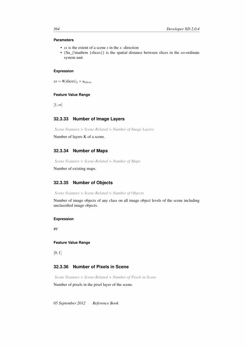
364 Developer XD 2.0.4
Parameters
• sx is the extent of a scene s in the x -direction• {$u_{\mathrm {slices}} is the spatial distance between slices in the co-ordinate
system unit
Expression
sx = #(slices)y×uslices
Feature Value Range
[1,∞]
32.3.33 Number of Image Layers
Scene Features > Scene-Related > Number of Image Layers
Number of layers K of a scene.
32.3.34 Number of Maps
Scene Features > Scene-Related > Number of Maps
Number of existing maps.
32.3.35 Number of Objects
Scene Features > Scene-Related > Number of Objects
Number of image objects of any class on all image object levels of the scene includingunclassified image objects.
Expression
#V
Feature Value Range
[0,1]
32.3.36 Number of Pixels in Scene
Scene Features > Scene-Related > Number of Pixels in Scene
Number of pixels in the pixel layer of the scene.
05 September 2012 Reference Book

Scene Features 365
Parameters
• sx is the scene extent in x• sy is the scene extent in y• sz is the scene extent in z• st is the scene extent in t• (sx,sy,sz,st) is the scene extent
Expression
sx× sy× sz× st
Feature Value Range
[0,scene extent]
32.3.37 Number of Samples
Scene Features > Scene-Related > Number of Samples
Number of all samples on all image object levels of the map.
Feature Value Range
[0,number of samples]
32.3.38 Number of Thematic Layers
Scene Features > Scene-Related > Number of Thematic Layers
The number of thematic layers layers included in the map.
32.3.39 Original Scene ID
Scene Features > Scene-Related > Original Scene ID
The original identification number of the scene. It is generated automatically by DefiniensDeveloper XD 2.0.4.
32.3.40 Original Scene Name
Scene Features > Scene-Related > Original Scene Name
The original name of the scene. It is generated automatically by Definiens Developer XD2.0.4.
Reference Book 05 September 2012

366 Developer XD 2.0.4
32.3.41 Scene ID
Scene Features > Scene-Related > Scene ID
The identification number of the scene. It is generated automatically by Definiens Devel-oper XD 2.0.4.
32.3.42 Scene Magnification
Scene Features > Scene-Related > Scene Magnification
Returns the scene magnification defined in a rule set.
32.3.43 Scene Name
Scene Features > Scene-Related > Scene Name
Returns the scene name.
32.3.44 Scene Pixel Size
Scene Features > Scene-Related > Scene Pixel Size
The scene unit that corresponds to one pixel, as defined in the metadata or in the ModifyProject dialog box.
32.3.45 Scene Resolution
Scene Features > Scene-Related > Scene Resolution
The resolution of the scene as given in the metadata of the project. The resulting numberrepresents the size of a pixel in co-ordinate system unit. The value is 1 if no resolution isset.
32.3.46 Scene Bits Per Sample
Scene Features > Scene-Related > Scene Bits per Sample
Returns a value if the program has read a bits per sample value in the metadata.1
32.3.47 Second Level Scene Name
Scene Features > Scene-Related > Second Level Scene Name
Displays the name of second-level scenes.
1. This feature was previously called Scene Bit Depth
05 September 2012 Reference Book

Scene Features 367
32.3.48 Slice Distance
Scene Features > Scene-Related > Slice Distance
The spatial distance between slices in the co-ordinate system unit.
Expression
uslices
32.3.49 TMA Core Position
Scene Features > Scene-Related > TMA Core Position
The TMA Core Position feature returns a string in the format “A7” for TMA Cores andtheir sibling scenes, such as tiles or subsets. For non-TMA cores, an empty string (“ “) isreturned.
32.3.50 TMA Core Type
Scene Features > Scene-Related > TMA Core Type
The TMA Core Type feature returns a string in the form of “positive”,”negative”, “empty”or “normal” for TMA cores and their child scenes, such as tiles or subsets. For non-TMAcores, an empty string (“ “) is returned.
32.3.51 TMA Number of Annotations
Scene Features > Scene-Related > TMA Number of Annotations
Returns the number of annotations in a TMA core.
32.3.52 Time Series Distance
Scene Features > Scene-Related > Time Series Distance
The temporal distance between slices in the time co-ordinate unit.
Expression
uframes
Reference Book 05 September 2012

368 Developer XD 2.0.4
32.3.53 Top Scene ID
Scene Features > Scene-Related > Top Scene ID
The identification number of the top scene.
A top scene is the original scene that was used to create scene copies, subsets, or tiles.2
32.3.54 User Name
Scene Features > Scene-Related > User Name
The user name.
32.4 Rule-Set Related
32.4.1 Class Variable
Scene Features > Rule-Set Related > Class Variable
Enter a name, color and value.
32.4.2 Level Variable
Scene Features > Rule-Set Related > Level Variable
Enter a name and value.
32.4.3 Map Name Variable
Scene Features > Rule-Set Related > Map Name Variable
Enter a name and value.
32.4.4 Image Layer Variable
Scene Features > Rule-Set Related > Image Layer Variable
Enter a name and value.
32.4.5 Thematic Layer Variable
Scene Features > Rule-Set Related > Thematic Layer Variable
Enter a name and value.
2. The Top Scene ID feature returns correct values in Definiens Developer XD only.
05 September 2012 Reference Book

Scene Features 369
32.4.6 Number of Features in Feature List
Scene Features > Rule-Set Related > Number of Features in Feature List
Enter a name and feature(s).
32.4.7 Number of Specified Features in Feature List
Scene Features > Rule-Set Related > Number of Specified Features in Feature List
Enter a name and feature(s) for the Feature List and Feature(s).
32.4.8 Rule Set Array Values
Scene Features > Rule-Set Related > Rule Set Array Values
Enter the name of an array.
32.4.9 Rule Set Array Size
Scene Features > Rule-Set Related > Rule Set Array Size
Enter the name of an array.
32.4.10 Rule Set Array Item
Scene Features > Rule-Set Related > Rule Set Array Item
Enter the name of an array and the index value to access an array item.
32.5 Architect Related
Scene Features > Rule-Set Related
32.5.1 Number of Actions
Scene Features > Rule-Set Related > Number of Actions
The Number of Actions features allows a rule set to keep track of the structure of theanalysis.
• If the value is 0, the action is not present in the library• If the value is 1, the action is present in the library• Where there are multiple actions, the value increases.
Reference Book 05 September 2012

370 Developer XD 2.0.4
32.6 File System
Scene Features > File System
32.6.1 Resolve Path
Scene Features > File System > Resolve Path
Resolve Path lets you enter a string that will be converted to a file path relative to theWorkspace folder. Paths can contain shortcuts and variables, which will be converted tothe file path.
Supported Shortcuts
Definiens Developer XD 2.0.4 will replace the following variables with actual values:
Shortcut Description
"{:Workspc.Name}" Name of the workspace
"{:Workspc.Guid}" GUID of the workspace
"{:Workspc.Dir}" Path of the workspace file
"{:Project.Name}" Name of the scene (absolute in the workspace)
"{:Project.Guid}" GUID of the scene
"{:Scene.Dir}" Directory of the scene
"{:Scene.Name}" Name of the scene
"{:ImgLayer(n).Dir}" Path to the input image layer n
"{:Workspc.OutputRoot}" Path of the output root
"{:Workspc.InputRoot}" Path of the input root
"{:ActionLib.Dir}" Directory of the action library (if any)
"{:Variable:abcde}" Value of variable abcde
"{:Application.Dir}" Directory of the loaded application/portal (if any)
Example
The Workspace file is located at C:\My Samples\Workspaces\1206\WKSP_20110111–1206.dpjand the value of the variable str_temp1 is 91.32.12. The Resolve Path feature will convertthe input path”{:Workspc.OutputRoot}\results\report_Variable [str_temp1].html” to”C:\My Samples\Workspaces\WKSP_20110111–1206\results\report_91.32.12.html”
32.7 UI Related
Scene Features > UI Related
05 September 2012 Reference Book

Scene Features 371
32.7.1 Equalization
Scene Features > UI Related > Equalization
Equalization features return the level equalization values selected by users (which can bechanged via the Edit Image Layer Mixing dialog box, or by dragging the mouse acrossthe image with the right mouse button, if this option is enabled in Tools > Options).
Equalization Mode
Values may be:
• Linear• Linear – Inverse• Gamma Correction (Positive)• Gamma Correction (Negative)• Gamma Correction (Positive) – Inverse• Gamma Correction (Negative) – Inverse
Window Level Center
The mid-point of the defined equalization range.
Window Level Max
The end-point of the defined equalization range.
Window Level Min
The beginning of the defined equalization range.
Window Level Width
The equalization range either side of the center (Window Level Max minus Window LevelMin)
Reference Book 05 September 2012


33 Process-Related Features
Process-related features are image object dependent features. They involve the relation-ship of a child process image object to a parent process. They are used in local processing.A process-related feature refers to a relation of an image objects to a parent process object(PPO) of a given process distance in the process hierarchy.
The process distance in the process hierarchy represents the upward distance of hierarchi-cal levels in process tree between a process and the parent process. The process distanceis a basic parameter of process-related features. Practically, that is the number of hierar-chy levels in the Process Tree window above the current editing line, in which you findthe definition of the parent object.
In the Process Tree, hierarchical levels are indicated by different indentations.
Figure 33.1. Process Tree window displaying a prototype of a process hierarchy. The pro-cesses are named according to their connection mode
For example, a process distance of 1 means that the parent process is located one hier-archical level above the current process. A process distance of 2 means that the parentprocess is located two hierarchical levels above the current process. Figuratively, youmay say, a process distance of 2 defines the “grandparent” process.
33.1 Customized
Process-Related Features > Customized
33.1.1 Diff. PPO
Process-Related Features > Customized > Create New Diff. PPO
373

374 Developer XD 2.0.4
Define a customized feature in relation to the difference between a given feature value ofan image object and the feature value of its parent process object (PPO).
Editable Parameters
• Distance: Upward distance of hierarchical levels in process tree between a processand the parent process.
• Feature
Parameters
• v is the image object• f is any feature• ρ is a parent process object (PPO)
Expression
f (v)− f (ρ)
Feature Value Range
The range depends on the value of the feature in use.
Conditions
If f (ρ) = 0 ∴ the formula is undefined.
33.1.2 Ratio PPO
Process-Related Features > Customized > Ratio PPO
Define a customized feature by the ratio between a given feature value of an image objectand the feature value of its parent process object (PPO).
Editable Parameters
• Distance: Upward distance of hierarchical levels in process tree between a processand the parent process.
• Feature
Parameters
• v is the image object• f is any feature• ρ is a parent process object (PPO)
05 September 2012 Reference Book
Process-Related Features 375
Expression
f (v)f (ρ)
Feature Value Range
The range depends on the value of the feature in use.
Conditions
If f (ρ) = 0 ∴ the formula is undefined.
33.2 Border to PPO
Process-Related Features > Border to PPO
The absolute border of an image object shared with its parent process object.
33.2.1 Editable Parameters
• Distance: Upward distance of hierarchical levels in process tree between a processand the parent process.
33.2.2 Parameters
• b(v,ρ) is the length of common border between v and ρ with the parent processobject
33.2.3 Expression
b(v,r)
33.2.4 Feature Value Range
[0,maximum size]
33.3 Distance to PPO
The distance between two parent process objects.
Reference Book 05 September 2012

376 Developer XD 2.0.4
33.3.1 Editable Parameter
• Distance: Upward distance of hierarchical levels in process tree between a processand the parent process.
33.4 Elliptic Dist. from PPO
Process-Related Features > Elliptic Dist. from PPO
The elliptic distance of an image object to its parent process object (PPO).
The ellipse is derived from area and center of gravity of the parent process object. Thefeature value is the distance between the center of gravity of the image object and theellipse.
33.4.1 Parameters
• xv, yv
33.4.2 Editable Parameters
• Metadata Name: Name of the metadata source as used in the Modify Project di-alog box. This name will be used in the feature tree for grouping correspondingmetadata items. You can type a name of a not existing metadata source, to create afeature group in advance.
• Name: Name of the metadata item as used in the source data.• Type: Select the type of the metadata item: string, double, or integer.• Distance: Upward distance of hierarchical levels in process tree between a process
and the parent process.
33.4.3 Expression
ερ(xv, yv)
33.4.4 Feature Value Range
[0,∞]
33.5 Rel. border to PPO
Process-Related Features > Rel. Border to PPO
The ratio of the border length of an image object shared with the parent process object(PPO) to its total border length.
05 September 2012 Reference Book

Process-Related Features 377
33.5.1 Editable Parameters
Process Distance: Upward distance of hierarchical levels in process tree between a pro-cess and the parent process.
33.5.2 Parameters
• bv is the image object border length• b(v,ρ) is the length of common border between v and ρ with the parent process
object
33.5.3 Expression
b(v,ρ)bv
33.5.4 Feature Value Range
[0,1]
33.6 Same Superobject as PPO
Process-Related Features > Same Super Object as PPO
The Same super object as PPO feature checks whether an image object and its parentprocess object (PPO) are parts of the same superobject.
33.6.1 Editable Parameters
• Process Distance: Upward distance of hierarchical levels in process tree between aprocess and the parent process.
33.6.2 Parameters
• v is the image object• ρ is the parent process object (PPO)• Uv(d) is the superobject of an image object v at a distance d
33.6.3 Expression
1 : Uv(d) = Uρ(d)0 : Uv(d) 6= Uρ(d)
Reference Book 05 September 2012
378 Developer XD 2.0.4
33.6.4 Feature Value Range
[0,1]
33.7 Series ID
Process-Related Features > Series ID
The Execute Child as Series algorithm executes its child domains based on the Number ofCycles parameter. For each execution, a unique identifier is generated and the parameterSeries Name prefixes this identifier. Therefore, if the domain has four image objects, andthe number of cycles is set to 1, the child processes will be executed four times (once foreach image object). On each cycle, the value attached to the series increases by one, forexample:
• 1st cycle = “series1”• 2nd cycle = “series2”
Therefore, the feature acts as a loop counter inside the Execute Child as Series algorithm.
05 September 2012 Reference Book

34 Customized Features
34.1 Stain2 Isolation
Customized > Stain2 Isolation
Stain2 Isolation lets you separate two stains (for example, Brown stain and Blue stain).
34.1.1 Editable Parameters
Mean of which stain
Choose from 1 or 2. These values correspond to the numbers in the Stain Calibrationparameters.
Input Layers
Select the image layers for the red, green and blue channels.
• Image layer red• Image layer green• Image layer blue
Stain Calibration
Enter the cx and cy values for the first (0) and second (1) stain these are converted fromRGB.1
• cx stain 0• cy stain 0• cx stain 1• cy stain 1
1. Van der Laak JAWM, Pahlplatz MMM, Hanselaar AGJM and De Wilde PCM (2000). Hue-Saturation-Density(HSD) Model for Stain Recognition in Digital Images From Transmitted Light Microscopy. Cytometry 39:275–284.
379

380 Developer XD 2.0.4
White Calibrations
Sample the the values for each layer in the background and enter the RGB values.
• White background red• White background green• White background blue
34.2 Stain3 Isolation
Customized > Stain3 Isolation
Stain2 Isolation lets you separate three stains.
34.2.1 Editable Parameters
Mean of which stain
Choose from 1, 2 or 3. These values correspond to the numbers in the Stain Calibrationparameters.
Input Layers
Select the image layers for the red, green and blue channels.
• Image layer red• Image layer green• Image layer blue
Stain Calibration
Enter the cx and cy values for the first (0), second (1) and third (2) stain these are con-verted from RGB.2
• cx stain 0• cy stain 0• cx stain 1• cy stain 1• cx stain 2• cy stain 2
2. Van der Laak JAWM, Pahlplatz MMM, Hanselaar AGJM and De Wilde PCM (2000). Hue-Saturation-Density(HSD) Model for Stain Recognition in Digital Images From Transmitted Light Microscopy. Cytometry 39:275–284.
05 September 2012 Reference Book

Customized Features 381
White Calibrations
Sample the the values for each layer in the background and enter the RGB values.
• White background red• White background green• White background blue
Reference Book 05 September 2012


35 Region Features
Region features return properties referring to a given region. They are global becausethey are not related to individual image objects. They are grouped as follows:
• Region-related features provide information on a given region.• Layer-related region features evaluate the first and second statistical moment
(mean, standard deviation) of a region’s pixel value.• Class-related region features provide information on all image objects of a given
class per region.
35.1 Region-Related
Region Features > Region-Related
Region-related features provide information on a given region.
35.1.1 Number of Pixels in Region
Region Features > Region-Related > Number of pixels in region
Number of pixel, voxels, or voxel series forming a region.
Editable Parameters
• Region
Parameters
• Rx is the region extent in x• Ry is the region extent in y• Rz is the region extent in z• Rt is the region extent in t
Expression
Rx×Ry×Rz×Rt
383

384 Developer XD 2.0.4
Feature Value Range
[0,∞]
35.1.2 T Extent
Region Features > Region Related > T Extent
Number of frames within a region.
Editable Parameters
• Region
Expression
Rt
Feature Value Range
[0,∞]
35.1.3 T Origin
Region Features > Region Related > T Origin
The t -co-ordinate of the origin of a region.
Editable Parameters
• Region
Expression
tG
Feature Value Range
[0,∞]
35.1.4 X Extent
Region Features > Region Related > X Extent
The extent of a region in x
05 September 2012 Reference Book

Region Features 385
Editable Parameters
• Region
Expression
Rx
Feature Value Range
[0,∞]
35.1.5 X Origin
Region Features > Region Related > X Origin
The x -co-ordinate of the origin of a region.
35.1.6 Y Extent
Region Features > Region Related > Y Extent
The pixel extent of a region in y .
Editable Parameters
• Region
Expression
xG
Feature Value Range
[0,∞]
35.1.7 Y Origin
Region Features > Region Related > Y Origin
The y -co-ordinate of the origin of a region.
Editable Parameters
• Region
Reference Book 05 September 2012

386 Developer XD 2.0.4
Expression
yG
Feature Value Range
[0,∞]
35.1.8 Z Extent
Region Features > Region Related > Z Extent
The number of slices within a region.
Editable Parameters
• Region
Expression
Rz
Feature Value Range
[0,∞]
35.1.9 Z Origin
Region Features > Region Related > Z Origin
The z -co-ordinate of the origin of a region.
Editable Parameter
• Region
Expression
zG
Feature Value Range
[0,∞]
05 September 2012 Reference Book

Region Features 387
35.2 Layer-Related
Region Features > Layer-Related
Layer-related region features evaluate the first and second statistical moment (mean, stan-dard deviation) of a region’s pixel value.
35.2.1 Mean
Region Features > Layer Related > Mean
Mean image layer value of a given image layer within a region.
Editable Parameters
• Region• Image layer
Parameters
• ck is the mean intensity of image layer k
Expression
ck(R)
Feature Value Range
[cminR ,cmax
R ]
35.2.2 Standard Deviation
Region Features > Layer Related > Std Dev
The layer standard deviation of a given image layer within a region.
Editable Parameters
• Region• Image layer
Parameters
• σk is the standard deviation of image layer k
Reference Book 05 September 2012

388 Developer XD 2.0.4
Expression
σk(R)
Feature Value Range
[cminR ,cmax
R ]
35.3 Class-Related
Region Features > Class Related
Class-related region features provide information on all image objects of a given classper region.
35.3.1 Area of Classified Objects
Region Features > Class Related > Area of Classified Objects
The absolute area in pixels, voxels, voxel series of all image objects classified as a givenclass on a given image object level within a region.
Editable Parameters
• Region• Class• Image object level
Parameters
• #P is the total number of pixels• i is the the given image object level• R is the the given region• m is the the given class
Expression
#Pi(R,m)
Feature Value Range
[0,Rx×Ry×Rz×Rt ]
05 September 2012 Reference Book
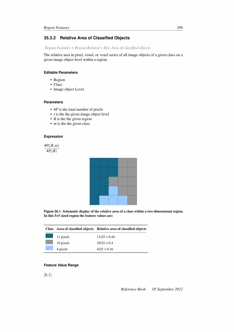
Region Features 389
35.3.2 Relative Area of Classified Objects
Region Features > Region-Related > Rel. Area of classified objects
The relative area in pixel, voxel, or voxel series of all image objects of a given class on agiven image object level within a region.
Editable Parameters
• Region• Class• Image object Level
Parameters
• #P is the total number of pixels• i is the the given image object level• R is the the given region• m is the the given class
Expression
#Pi(R,m)#Pi(R)
Figure 35.1. Schematic display of the relative area of a class within a two dimensional region.In this 5×5 sized region the feature values are:
Class Area of classified objects Relative area of classified objects
11 pixels 11/25 = 0.44
10 pixels 10/25 = 0.4
4 pixels 4/25 = 0.16
Feature Value Range
[0,1]
Reference Book 05 September 2012


36 Image Registration Features
Region Features > Image Registration Features
36.1 Object-Related
Region Features > Image Registration Features > Object Related
36.1.1 Object Landmarks on the Map
Region Features > Image Registration Features > Object Related > Object Landmarkson the Map
Returns the number of landmarks within the image object in the current map.
36.2 Scene-Related
Region Features > Image Registration Features > Scene Related
36.2.1 Landmarks on the Map
Region Features > Image Registration Features > Object Related > Landmarks on theMap
Returns the number of landmarks with the current map.
391

37 Metadata
Metadata items can be used as a feature in rule set development. To do so, you haveto provide external metadata in the feature tree. If you are not using data import proce-dures to convert external source metadata to internal metadata definitions, you can createindividual features from a single metadata item.
37.1 [Metadata Item]
Metadata > [Metadata item]
If existing, all metadata items are listed in the feature tree.
You can define a new metadata item by clicking on Create new Metadata item.
37.1.1 Editable Parameters
• Map• Metadata Name: Name of the metadata source as used in the Modify Project di-
alog box. This name will be used in the feature tree for grouping correspondingmetadata items. You can type a name of a not existing metadata source, to create afeature group in advance.
• Metadata Access: Select the mode of accessing the metadata:– Direct: Metadata is accessed by the name of the metadata item– Conversion: Metadata is converted as defined in the Metadata Conversion
dialog box• Name: Name of the metadata item as used in the source data.• Value: If Metadata Access is set to Conversion , you can define an internal metadata
item value , which can be different from the external value.• Type: Select the type of the metadata item: string, double, or integer.
37.2 [Active Slice Metadata Item]
Metadata > [Active Slice Metadata Item]
Where a project are made up of multiple image slices, there may be different metadatavalues on every slice this is especially the case for DICOM images. The Active SliceMetadata Item feature allows you to capture metadata values for the image slice in thecurrent active view.
393

394 Developer XD 2.0.4
37.2.1 Editable Parameters
• Metadata Name: Name of the metadata source as used in the Modify Project di-alog box. This name will be used in the feature tree for grouping correspondingmetadata items. You can type a name of a not existing metadata source, to create afeature group in advance.
• Name: Name of the metadata item as used in the source data.• Type: Select the type of the metadata item: string, double, or integer.
05 September 2012 Reference Book

38 Feature Variables
Feature Variables have features as their values. Once a feature is assigned to a featurevariable, the feature variable can be used like that feature. It returns the same value as thefeature to which it points. It uses the unit of whatever feature is assigned as a variable.It is possible to create a feature variable without a feature assigned, but the calculationvalue would be invalid.
In a rule set, feature variables can be used like the corresponding feature.
38.1 [Feature Variable]
Feature Variables > [Feature variable]
If existing, all variables that use features as values are listed in the feature tree. You candefine a new feature variable by clicking on Create New Feature Variable.
38.1.1 Editable Parameters
• Name• Value: The selected feature.
395


39 Widget Parameters forArchitect Action Libraries
Listed below are all available widgets and parameters for use in Action Libraries.Definiens Developer XD 2.0.4 now has additional features that allow you to display TIFFimages: if you use these functions, ensure your images are stored in the same folder asyour Action Library, to ensure they will be visible to other users.
39.1 Add Checkbox
• Text: Enter the text that will be displayed to the user• Description: Enter a description of your widget. The text will appear in the De-
scription pane when the cursor hovers over the widget. You may have a text de-scription or an image description, but not both
• Description Image: Allows you to display a TIFF image in the Description pane(transparency is supported). You may have a text description or an image descrip-tion, but not both
• Show/Hide Variable: Enter or select the name of the variable that defines whetherthe widget is visible. If you enter 0, the widget is hidden
• Enable/Disable Variable: Enter or select the name of the variable that defineswhether the widget is enabled or disabled. A zero value defines the widget state asdisabled
• Variable: Select or enter the variable that gets updated by this control• Value Checked: The value of the variable if the checkbox is checked• Value Unchecked: The value of the variable if the checkbox is unchecked• Process on Change: The name of the process that will be executed when a user
changes a value
39.2 Add Drop-down List
• Text: Enter the text that will be displayed to the user• Description: Enter a description of your widget. The text will appear in the De-
scription pane when the cursor hovers over the widget. You may have a text de-scription or an image description, but not both
• Description Image: Allows you to display a TIFF image in the Description pane(transparency is supported). You may have a text description or an image descrip-tion, but not both
397

398 Developer XD 2.0.4
• Show/Hide Variable: Enter or select the name of the variable that defines whetherthe widget is visible. If you enter 0, the widget is hidden
• Enable/Disable Variable: Enter or select the name of the variable that defineswhether the widget is enabled or disabled. A zero value defines the widget state asdisabled
• Variable: Select or enter the variable that gets updated by this control• Process on Selection Change: The name of the process that will be executed when
the selection changes• Items: Add or edit the items in the drop-down list
39.3 Add Button
• Text: Enter the text that will be displayed to the user• Description: Enter a description of your widget. The text will appear in the De-
scription pane when the cursor hovers over the widget. You may have a text de-scription or an image description, but not both
• Description Image: Allows you to display a TIFF image in the Description pane(transparency is supported). You may have a text description or an image descrip-tion, but not both
• Show/Hide Variable: Enter or select the name of the variable that defines whetherthe widget is visible. If you enter 0, the widget is hidden
• Enable/Disable Variable: Enter or select the name of the variable that defineswhether the widget is enabled or disabled. A zero value defines the widget state asdisabled
• Process on Press: Enter the name of the process executed when the button ispressed
• Process on Release: Enter the name of the process executed when the button isreleased
• Button Text: Enter the text to be displayed on the button• Image: Allows you to display a TIFF image (transparency is supported)• Radio Button: If set to ‘yes’, a radio button is displayed• Ruleset: Navigate to the ruleset (.dcp file) containing the processes to be executed
39.4 Add Radio Button Row
• Rule Set: Navigate to the ruleset (.dcp file) containing the processes to be executed• Radio Mode: If set to ‘true’, the buttons become radio buttons; if set to ‘false’ they
are normal buttons• Show/Hide Variable: Enter or select the name of the variable that defines whether
the widget is visible. If you enter 0, the widget is hidden• Enable/Disable Variable: Enter or select the name of the variable that defines
whether the widget is enabled or disabled. A zero value defines the widget state asdisabled
• Action Buttons:– Text: Enter the text to be displayed on the action button– Description: Enter a description to appear at the bottom of the description
pane. The text will also display as a tooltip. You may have a text descriptionor an image description, but not both
05 September 2012 Reference Book
Widget Parameters for Architect Action Libraries 399
– Description Image: Add a TIFF image to the description area (transparencyis supported). You may have a text description or an image description, butnot both
– Process Path: Enter the process path to be executed by the action button– Process Path on Release: Enter the process path to be executed when the
button is released– Execute on a Separate Thread: If set to ‘yes’, the process will be executed on
a separate thread– Image File: Navigate to the path of the image file for the button image– Highlight Image File: Navigate to the path of the image file for the high-
lighted button image– Hot Key: Lets you define a single hot key to execute an action– Radio Mode: Select ‘push button’ to use this style specifically; if ‘from wid-
get’ is selected, the radio mode from the widget is used
39.5 Add Toolbar
• Text: Enter the text that will be displayed to the user• Description: Enter a description of your widget. The text will appear in the De-
scription pane when the cursor hovers over the widget. You may have a text de-scription or an image description, but not both
• Description Image: Allows you to display a TIFF image in the Description pane(transparency is supported). You may have a text description or an image descrip-tion, but not both
• Show/Hide Variable: Enter or select the name of the variable that defines whetherthe widget is visible. If you enter 0, the widget is hidden
• Enable/Disable Variable: Enter or select the name of the variable that defineswhether the widget is enabled or disabled. A zero value defines the widget state asdisabled
• Variable: Select or enter the variable that gets updated by this control• Process on Change: The name of the process that will be executed when a user
changes a value
39.6 Add Editbox
• Text: Enter the text that will be displayed to the user• Description: Enter a description of your widget. The text will appear in the De-
scription pane when the cursor hovers over the widget. You may have a text de-scription or an image description, but not both
• Description Image: Allows you to display a TIFF image in the Description pane(transparency is supported). You may have a text description or an image descrip-tion, but not both
• Show/Hide Variable: Enter or select the name of the variable that defines whetherthe widget is visible. If you enter 0, the widget is hidden
• Enable/Disable Variable: Enter or select the name of the variable that defineswhether the widget is enabled or disabled. A zero value defines the widget state asdisabled
• Variable: Select or enter the variable that gets updated by this control
Reference Book 05 September 2012

400 Developer XD 2.0.4
• Process on Change: The name of the process that will be executed when a userchanges a value
39.7 Add Editbox With Slider
• Text: Enter the text that will be displayed to the user• Description: Enter a description of your widget. The text will appear in the De-
scription pane when the cursor hovers over the widget. You may have a text de-scription or an image description, but not both
• Description Image: Allows you to display a TIFF image in the Description pane(transparency is supported). You may have a text description or an image descrip-tion, but not both
• Show/Hide Variable: Enter or select the name of the variable that defines whetherthe widget is visible. If you enter 0, the widget is hidden
• Enable/Disable Variable: Enter or select the name of the variable that defineswhether the widget is enabled or disabled. A zero value defines the widget state asdisabled
• Variable: Select or enter the variable that gets updated by this control• Process on Change: The name of the process that will be executed when a user
changes a value• Maximum Value: Enter the maximum value for the slider• Minumum Value: Enter the minimum value for the slider• Tick Frequency: Enter a value to define how often tick marks appear next to the
slider• Jump Value: Enter a value to define the increments when the slider is moved• Ruleset: Navigate to the ruleset (.dcp file) containing the processes to be executed
39.8 Add Select Class
• Text: Enter the text that will be displayed to the user• Variable: Select or enter the variable that gets updated by this control• Available Classes: Select the classes to be made available (if none are selected,
classes are displayed based on action dependencies)• Process on Selection Change: Enter the name of the process to be executed when
a selection changes• Dependency Handling: The dependency effect of the selected class. Choose from
one of the following:– None– Required. This activates the parameter Dependency Error Message, which is
displayed when a dependency conflict occurs. Use the tag #class within theerror text to identify the class name
– Forbidden. This activates the parameter Dependency Error Message, whichis displayed when a dependency conflict occurs. Use the tag #class withinthe error text to identify the class name
– Added– Removed
• Allow Create New Class: Select ‘yes’ to allow the user to create a new class fromthe widget.
05 September 2012 Reference Book

Widget Parameters for Architect Action Libraries 401
• Description: Enter a description of your widget. The text will appear in the De-scription pane when the cursor hovers over the widget. You may have a text de-scription or an image description, but not both
• Description Image: Allows you to display a TIFF image in the Description pane(transparency is supported). You may have a text description or an image descrip-tion, but not both
• Show/Hide Variable: Enter or select the name of the variable that defines whetherthe widget is visible. If you enter 0, the widget is hidden
• Enable/Disable Variable: Enter or select the name of the variable that defineswhether the widget is enabled or disabled. A zero value defines the widget state asdisabled
39.9 Add Select Feature
• Text: Enter the text that will be displayed to the user• Variable: Select or enter the variable that gets updated by this control• Type: Select the filter type for selectable features – all, scene features or object
features• Description: Enter a description of your widget. The text will appear in the De-
scription pane when the cursor hovers over the widget. You may have a text de-scription or an image description, but not both
• Description Image: Allows you to display a TIFF image in the Description pane(transparency is supported). You may have a text description or an image descrip-tion, but not both
• Show/Hide Variable: Enter or select the name of the variable that defines whetherthe widget is visible. If you enter 0, the widget is hidden
• Enable/Disable Variable: Enter or select the name of the variable that defineswhether the widget is enabled or disabled. A zero value defines the widget state asdisabled
• Process on Change: The name of the process that will be executed when a userchanges a value
39.10 Add Select Multiple Features
• Text: Enter the text that will be displayed to the user• Image File: Navigate to the path of the image file for the button image• Highlight Image File: Navigate to the path of the image file for the highlighted
button image• Variable: Select or enter the variable that gets updated by this control• Type: Select the filter type to be used:
– All– Object Features– Scene Features– Custom Filter – this option brings up the Custom Feature Filter parameter,
which allows you to select which features are available for selection• Show Template Features: Select ‘yes’ to show template features, while selecting
features
Reference Book 05 September 2012

402 Developer XD 2.0.4
• Description: Enter a description of your widget. The text will appear in the De-scription pane when the cursor hovers over the widget. You may have a text de-scription or an image description, but not both
• Description Image: Allows you to display a TIFF image in the Description pane(transparency is supported). You may have a text description or an image descrip-tion, but not both
• Show/Hide Variable: Enter or select the name of the variable that defines whetherthe widget is visible. If you enter 0, the widget is hidden
• Enable/Disable Variable: Enter or select the name of the variable that defineswhether the widget is enabled or disabled. A zero value defines the widget state asdisabled
• Process on Change: The name of the process that will be executed when a userchanges a value
39.11 Add Select File
• Text: Enter the text that will be displayed to the user• Description: Enter a description of your widget. The text will appear in the De-
scription pane when the cursor hovers over the widget. You may have a text de-scription or an image description, but not both
• Description Image: Allows you to display a TIFF image in the Description pane(transparency is supported). You may have a text description or an image descrip-tion, but not both
• Show/Hide Variable: Enter or select the name of the variable that defines whetherthe widget is visible. If you enter 0, the widget is hidden
• Enable/Disable Variable: Enter or select the name of the variable that defineswhether the widget is enabled or disabled. A zero value defines the widget state asdisabled
• Variable for File: Add or select the variable that gets updated by this control• File Filter: Add a filter for file type, for example *.tif or *.*• Type: Select the file to be selected:
– Image– Thematic: If this option is selected, two more parameters appear:
* Variable for Attribute File, to be updated by this control* Variable for Attribute ID Column, to be updated by this control
• Mode: Select between ‘open’ and ‘save’• Process on Change: The name of the process that will be executed when a user
changes a value
39.12 Add Select Level
• Text: Enter the text that will be displayed to the user• Variable: Select or enter the variable that gets updated by this control• Show all Levels: If set to ‘yes’, action dependencies for listing available levels are
ignored• Process on Selection Change: The name of the process that will be executed when
the selection changes• Show Pixel Level: Select ‘yes’ to show the pixel level
05 September 2012 Reference Book

Widget Parameters for Architect Action Libraries 403
• Dependency Handling: The dependency effect of the selected class. Choose fromone of the following:
– None– Required. This activates the parameter Dependency Error Message, which is
displayed when a dependency conflict occurs. Use the tag #class within theerror text to identify the class name
– Forbidden. This activates the parameter Dependency Error Message, whichis displayed when a dependency conflict occurs. Use the tag #class withinthe error text to identify the class name
– Added– Removed
• Description: Enter a description of your widget. The text will appear in the De-scription pane when the cursor hovers over the widget. You may have a text de-scription or an image description, but not both
• Description Image: Allows you to display a TIFF image in the Description pane(transparency is supported). You may have a text description or an image descrip-tion, but not both
• Show/Hide Variable: Enter or select the name of the variable that defines whetherthe widget is visible. If you enter 0, the widget is hidden
• Enable/Disable Variable: Enter or select the name of the variable that defineswhether the widget is enabled or disabled. A zero value defines the widget state asdisabled
39.13 Add Select Image Layer
• Text: Enter the text that will be displayed to the user• Variable: Select or enter the variable that gets updated by this control• Process on Selection Change: The name of the process that will be executed when
the selection changes• Description: Enter a description of your widget. The text will appear in the De-
scription pane when the cursor hovers over the widget. You may have a text de-scription or an image description, but not both
• Description Image: Allows you to display a TIFF image in the Description pane(transparency is supported). You may have a text description or an image descrip-tion, but not both
• Show/Hide Variable: Enter or select the name of the variable that defines whetherthe widget is visible. If you enter 0, the widget is hidden
• Enable/Disable Variable: Enter or select the name of the variable that defineswhether the widget is enabled or disabled. A zero value defines the widget state asdisabled
39.14 Add Select Thematic Layer
• Text: Enter the text that will be displayed to the user• Variable: Select or enter the variable that gets updated by this control• Process on Selection Change: The name of the process that will be executed when
the selection changes
Reference Book 05 September 2012
404 Developer XD 2.0.4
• Description: Enter a description of your widget. The text will appear in the De-scription pane when the cursor hovers over the widget. You may have a text de-scription or an image description, but not both
• Description Image: Allows you to display a TIFF image in the Description pane(transparency is supported). You may have a text description or an image descrip-tion, but not both
• Show/Hide Variable: Enter or select the name of the variable that defines whetherthe widget is visible. If you enter 0, the widget is hidden
• Enable/Disable Variable: Enter or select the name of the variable that defineswhether the widget is enabled or disabled. A zero value defines the widget state asdisabled
39.15 Add Select Folder
• Text: Enter the text that will be displayed to the user• Description: Enter a description of your widget. The text will appear in the De-
scription pane when the cursor hovers over the widget. You may have a text de-scription or an image description, but not both
• Description Image: Allows you to display a TIFF image in the Description pane(transparency is supported). You may have a text description or an image descrip-tion, but not both
• Show/Hide Variable: Enter or select the name of the variable that defines whetherthe widget is visible. If you enter 0, the widget is hidden
• Enable/Disable Variable: Enter or select the name of the variable that defineswhether the widget is enabled or disabled. A zero value defines the widget state asdisabled
• Variable: Select or enter the variable that gets updated by this control• Process on Change: The name of the process that will be executed when a user
changes a value
39.16 Add Slider
• Text: Enter the text that will be displayed to the user• Description: Enter a description of your widget. The text will appear in the De-
scription pane when the cursor hovers over the widget. You may have a text de-scription or an image description, but not both
• Description Image: Allows you to display a TIFF image in the Description pane(transparency is supported). You may have a text description or an image descrip-tion, but not both
• Show/Hide Variable: Enter or select the name of the variable that defines whetherthe widget is visible. If you enter 0, the widget is hidden
• Enable/Disable Variable: Enter or select the name of the variable that defineswhether the widget is enabled or disabled. A zero value defines the widget state asdisabled
• Variable: Select or enter the variable that gets updated by this control• Process on Change: The name of the process that will be executed when a user
changes a value• Maximum Value: Enter the maximum value for the slider• Minumum Value: Enter the minimum value for the slider
05 September 2012 Reference Book

Widget Parameters for Architect Action Libraries 405
• Tick Frequency: Enter a value to define how often tick marks appear next to theslider
• Jump Value: Enter a value to define the increments when the slider is moved• Ruleset: Navigate to the ruleset (.dcp file) containing the processes to be executed
39.17 Add Edit Layer Names
• Text: Enter the text that will be displayed to the user• Tooltip: Enter the text to appear as a tooltip• Image File: Navigate to the path of the image file for the button image• Highlight Image File: Navigate to the path of the image file for the highlighted
button image• Button Size: Button size in pixels• Description: Enter a description of your widget. The text will appear in the De-
scription pane when the cursor hovers over the widget. You may have a text de-scription or an image description, but not both
• Description Image: Allows you to display a TIFF image in the Description pane(transparency is supported). You may have a text description or an image descrip-tion, but not both
• Show/Hide Variable: Enter or select the name of the variable that defines whetherthe widget is visible. If you enter 0, the widget is hidden
• Enable/Disable Variable: Enter or select the name of the variable that defineswhether the widget is enabled or disabled. A zero value defines the widget state asdisabled
39.18 Add Layer Drop-down List
• Text: Enter the text that will be displayed to the user• Description: Enter a description of your widget. The text will appear in the De-
scription pane when the cursor hovers over the widget. You may have a text de-scription or an image description, but not both
• Description Image: Allows you to display a TIFF image in the Description pane(transparency is supported). You may have a text description or an image descrip-tion, but not both
• Show/Hide Variable: Enter or select the name of the variable that defines whetherthe widget is visible. If you enter 0, the widget is hidden
• Enable/Disable Variable: Enter or select the name of the variable that defineswhether the widget is enabled or disabled. A zero value defines the widget state asdisabled
• Items: Add or edit the items in the drop-down list• Process on Selection Change: The name of the process that will be executed when
the selection changes
39.19 Add Manual Classification Buttons
• Rule Set: Navigate to the ruleset (.dcp file) containing the processes to be executed• Mode: Choose between push button or checkbox
Reference Book 05 September 2012

406 Developer XD 2.0.4
• Show Edit Classes Button: Select ‘yes’ to display the Edit Classes button, whichallows users to change the class names and colors of widget classes
• Image File for Edit Classes: Navigate to the path of the image file for the buttonimage
• Show/Hide Variable: Enter or select the name of the variable that defines whetherthe widget is visible. If you enter 0, the widget is hidden
• Enable/Disable Variable: Enter or select the name of the variable that defineswhether the widget is enabled or disabled. A zero value defines the widget state asdisabled
• Action Buttons:– Class: Assign a class to the button– Description: Enter a description to appear at the bottom of the description
pane. The text will also display as a tooltip– Description Image: Add a TIFF image to the description area (transparency
is supported). Uploading an image will replace the text in the description inthe description area. You may have a text description or an image description,but not both
– Process Path: Enter the process path to be executed by the action button– Process Path on Release: Enter the process path to be executed when the
button is released– Hot Key: Lets you define a single hot key to execute an action
39.20 Add Select Array Items
• Text: Enter the text that will be displayed to the user• Items: Enter a name then select the array that defines the selectable items• Selected Items: Enter a name then select the array that receives the selectable
items• Process on Change: The name of the process that will be executed when a user
changes a value• Description: Enter a description to appear at the bottom of the description pane.
The text will also display as a tooltip• Description Image: Add a TIFF image to the description area (transparency is
supported). Uploading an image will replace the text in the description in the de-scription area. You may have a text description or an image description, but notboth
• Show/Hide Variable: Enter or select the name of the variable that defines whetherthe widget is visible. If you enter 0, the widget is hidden
• Enable/Disable Variable: Enter or select the name of the variable that defineswhether the widget is enabled.
05 September 2012 Reference Book

40 General Reference
40.1 Use Variables as Features
The following variables can be used as features:
• Scene variables• Object variables• Class variables• Feature variables.
They are displayed in the feature tree of, for example, the Feature View window or theSelect Displayed Features dialog box.
40.2 About Metadata as a Source of Information
Many image data formats include metadata or come with separate metadata files, whichprovide information about the related image (for example, the acquisition time). Thismetadata information can be converted into features, to use in image analysis.
The available metadata depends on the image reader or camera used, the industry-specificenvironment, and the settings. Some industry-specific examples are:
• Satellite image data containing metadata providing information on cloudiness• Microscopy image data that contains metadata on the magnification used. The
metadata provided can be displayed in the Image Object Information window andcan also be displayed in the feature tree, in the Feature View window or the SelectDisplayed Features dialog box.
40.2.1 Convert Metadata and Add it to the Feature Tree
When importing data, you can load metadata source files to make them available withinthe map. To provide external metadata items as features in the feature tree, you mustconvert external source metadata to an internal metadata definition.
When developing rule sets, metadata definitions will be included in rule sets allowingthe serialization of metadata usage. Metadata conversion is available through importfunctions and creating metadata item features.
407

408 Developer XD 2.0.4
40.3 General Reference
40.3.1 Rendering a Displayed Image
1. The first step reads out the displayed area from the selected image layers accordingto the screen size and zoom settings. Then image layer equalization is applied. Theresult is an 8-bit raw gray value image for each image layer. These gray value im-ages are mixed into one raw RGB image by a layer mixer according to the currentlayer mixing settings
2. Finally the image equalizing is applied to create the output RGB image that isdisplayed on the screen.
Figure 40.1. The rendering process of an image displayed in the map view
Image Layer Equalization
Image layer equalization is part of the rendering process of the scene display within themap view.
Image layer equalization maps the input data of an image layer which may have differentintensity ranges to the unified intensity range [0. . . 255] of an 8-bit gray value image.For 8-bit data no image layer equalization is necessary. All other data types have to beconverted into an 8-bit representation at this step of the rendering process.
This function is implemented as a mapping of the input range to the display range of[0. . . 255]. Image layer equalization can be either linear or manual. By default, the inputdata is mapped to the gray value range by a linear function.
Data Type Input Range Mapping Function
8-bit [0 . . .255] cs = ck(no transformation)
16-bit unsigned; 32-bit unsigned [0 . . .max2(ck)]cs = 255× ck
max2(ck)
16-bit signed; 32-bit signed [min2(ck) . . .max2(ck)]cs = 255× (ck−min2(ck))
max2(ck)−min2(ck)
32 bit float [min10(ck) . . .max10(ck)]cs = 255× (ck−min10(ck))
max10(ck)−min10(ck)
• ck is the intensity value in image layer k• cs is the intensity value on the screen
05 September 2012 Reference Book

General Reference 409
• min2(ck) = max{x : x = −2n;x ≤ c′ mink } is the highest integer number that is a
power of 2 and darker than the darkest actual intensity value of all pixel values ofthe selected image layer
• max2(ck) = max{x : x = 2n;x≥ c′ maxk } is the lowest integer number that is a power
of 2 and is brighter than the brightest actual intensity value of all pixel values ofthe selected image layer
• min10(ck) = max{x : x = −10n;x ≤ c′ mink } is the highest integer number that is a
power of 10 and darker than the darkest actual intensity value of all pixel values ofthe selected image layer
• max10(ck) = max{x : x = 10n;x ≥ c′ maxk } is the lowest integer number that is a
power of 10 and is brighter than the brightest actual intensity value of all pixelvalues of the selected image layer.
Manual Image Layer Equalization With manual image layer equalization you can spec-ify the mapping function for each layer individually by defining both the input range[cmin . . .cmax] and the mapping function.
Data Type Mapping Function
Linear cs = 255× (ck− cmin)÷ (cmax− cmin)
Linear – inverse cs = 255−255× (ck− cmin)÷ (cmax− cmin)
Gamma correction (positive) cs = 255× ((ck− cmin)÷ (cmax− cmin))2
Gamma correction (negative) cs = 255× ((ck− cmin)÷ (cmax− cmin))0.5
Gamma correction (positive) – inverse cs = 255−255× ((ck− cmin)÷ (cmax− cmin))2
Gamma correction (negative) – inverse cs = 255−255× ((ck− cmin)÷ (cmax− cmin))0.5
• ck is the intensity value in image layer k• cs is the intensity value on the screen• cmin is the smallest input intensity value (adjustable)• cmax is the largest input intensity value (adjustable).
Image Equalization
Image equalization is performed after all image layers are mixed into a raw RGB (red,green, blue) image. If more than one image layer is assigned to one screen color (red,green or blue) this approach leads to higher quality results. Where only one image layeris assigned to each color, as is common, this approach is the same as applying equalizationto the individual raw layer gray value images
There are different modes for image equalization available. All of them rely on imagestatistics. These are computed on the basis of a 256 × 256 pixel sized thumbnail of thecurrent raw RGB image.
None No (None) equalization allows you to see the image data as it is, which can behelpful at the beginning of rule set development, when looking for an approach. Theoutput from the image layer mixing is displayed without further modification.
• [0 . . .255] is the input range
Reference Book 05 September 2012

410 Developer XD 2.0.4
• [0 . . .255] is the mapping function
Linear Equalization Linear equalization with 1.00% is the default for new scenes. Com-monly it displays images with a higher contrast as without image equalization.
Linear equalization maps each color – red, green, and blue – from an input range[cmin . . .cmax] to the available screen intensity range [0 . . .255] by a linear mapping. Theinput range can be modified by the percentage parameter p. The input range is computedsuch that p per cent of the pixels are not part of the input range. In case p = 0 this meansthe range of used color values is stretched to the range [0 . . .255] . For p > 0 the mappingignores p
2 per cent of the darkest pixels and p2 per cent of the brightest pixels. In many
cases a small value of p leads to better results because the available color range can bebetter used for the relevant data by ignoring the outliers.
• cmin =max{c : #{(x,y) : ck(x,y) < cmin}
(sx× sy)≥ p2
• cmax =min{c : #{(x,y) : ck(x,y) > cmax}
(sx× sy)≥ p2
• [cmin . . .cmax] is the input range
• cs = 255×(
ck− cmin
cmax− cmin
)is the mapping function.
Standard Deviation Equalization With its default parameter of 3.0, standard deviation ren-ders a similar display as linear equalization. Use a parameter around 1.0 for an exclusionof dark and bright outliers.
Standard deviation equalization maps the input range to the available screen intensityrange [0 . . .255] by a linear mapping. The input range [cmin . . .cmax] can be modified bythe width p. The input range is computed such that the center of the input range representsthe mean value of the pixel intensities mean (ck). The left and right borders of the inputrange are computed by taking n times the standard deviation σk to the left and the right.You can modify the parameter n.
• cmin = mean(ck)−n×σk• cmax = mean(ck)+n×σk• [cmin . . .cmax] is the input range
• cs = 255×(
ck− cmin
cmax− cmin
)is the mapping function.
Gamma Correction Equalization Gamma correction equalization is used to improve thecontrast of dark or bright areas by spreading the corresponding gray values. Gamma cor-rection equalization maps the input range to the available screen intensity range [0 . . .255]by a polynomial mapping. The input range [cmin . . .cmax] cannot be be modified and isdefined by the smallest and the largest existing pixel values.
• cmin = c′ mink – the smallest existing pixel values
• cmax = c′ maxk – the largest existing pixel values
• [cmin . . .cmax] is the input range
• cs = 255×(
ck− cmin
cmax− cmin
)n
is the mapping function.
05 September 2012 Reference Book

General Reference 411
You can be modify the exponent of the mapping function by editing the equalizationparameter. Values of n less than 1 emphasize darker regions of the image, values largerthan one emphasize darker areas of the image. A value from n = 1 represents the linearcase.
Histogram Equalization Histogram equalization is well suited for LANDSAT images butcan lead to substantial over-stretching on many normal images. It can be helpful in casesyou want to display dark areas with more contrast. Histogram equalization maps the inputrange to the available screen intensity range [0 . . .255] by a nonlinear function. Simplysaid, the mapping is defined by the property that each color value of the output imagerepresents the same number of pixels. The respective algorithm is more complex and canbe found in standard image processing literature.
Manual Image Layer Equalization Manual image layer equalization allows you to controlequalization in detail. For each image layer individually, you can set the equalizationmethod specifying the mapping function. Further you can define the input range by set-ting minimum and maximum values.
Reference Book 05 September 2012


Acknowledgments
Portions of this product are based in part on the third-party software components.Definiens is required to include the following text, with software and distributions.
The Visualization Toolkit (VTK) Copyright
This is an open-source copyright as follows:
Copyright © 1993–2006 Ken Martin, Will Schroeder and Bill Lorensen.
All rights reserved.
Redistribution and use in source and binary forms, with or without modification, arepermitted provided that the following conditions are met:
• Redistributions of source code must retain the above copyright notice, this list ofconditions and the following disclaimer.
• Redistributions in binary form must reproduce the above copyright notice, this listof conditions and the following disclaimer in the documentation and/or other mate-rials provided with the distribution.
• Neither name of Ken Martin, Will Schroeder, or Bill Lorensen nor the names ofany contributors may be used to endorse or promote products derived from thissoftware without specific prior written permission.
THIS SOFTWARE IS PROVIDED BY THE COPYRIGHT HOLDERS AND CON-TRIBUTORS “AS IS” AND ANY EXPRESS OR IMPLIED WARRANTIES, INCLUD-ING, BUT NOT LIMITED TO, THE IMPLIED WARRANTIES OF MERCHANTABIL-ITY AND FITNESS FOR A PARTICULAR PURPOSE ARE DISCLAIMED. IN NOEVENT SHALL THE AUTHORS OR CONTRIBUTORS BE LIABLE FOR ANY DI-RECT, INDIRECT, INCIDENTAL, SPECIAL, EXEMPLARY, OR CONSEQUENTIALDAMAGES (INCLUDING, BUT NOT LIMITED TO, PROCUREMENT OF SUBSTI-TUTE GOODS OR SERVICES; LOSS OF USE, DATA, OR PROFITS; OR BUSINESSINTERRUPTION) HOWEVER CAUSED AND ON ANY THEORY OF LIABILITY,WHETHER IN CONTRACT, STRICT LIABILITY, OR TORT (INCLUDING NEGLI-GENCE OR OTHERWISE) ARISING IN ANY WAY OUT OF THE USE OF THISSOFTWARE, EVEN IF ADVISED OF THE POSSIBILITY OF SUCH DAMAGE.
ITK Copyright
E
Copyright © 1999–2003 Insight Software Consortium
All rights reserved.
413

414 Developer XD 2.0.4
Redistribution and use in source and binary forms, with or without modification, arepermitted provided that the following conditions are met:
• Redistributions of source code must retain the above copyright notice, this list ofconditions and the following disclaimer.
• Redistributions in binary form must reproduce the above copyright notice, this listof conditions and the following disclaimer in the documentation and/or other mate-rials provided with the distribution.
• Neither the name of the Insight Software Consortium nor the names of its con-tributors may be used to endorse or promote products derived from this softwarewithout specific prior written permission.
THIS SOFTWARE IS PROVIDED BY THE COPYRIGHT HOLDERS AND CON-TRIBUTORS “AS IS” AND ANY EXPRESS OR IMPLIED WARRANTIES, INCLUD-ING, BUT NOT LIMITED TO, THE IMPLIED WARRANTIES OF MERCHANTABIL-ITY AND FITNESS FOR A PARTICULAR PURPOSE ARE DISCLAIMED. IN NOEVENT SHALL THE COPYRIGHT OWNER OR CONTRIBUTORS BE LIABLE FORANY DIRECT, INDIRECT, INCIDENTAL, SPECIAL, EXEMPLARY, OR CONSE-QUENTIAL DAMAGES (INCLUDING, BUT NOT LIMITED TO, PROCUREMENTOF SUBSTITUTE GOODS OR SERVICES; LOSS OF USE, DATA, OR PROFITS; ORBUSINESS INTERRUPTION) HOWEVER CAUSED AND ON ANY THEORY OFLIABILITY, WHETHER IN CONTRACT, STRICT LIABILITY, OR TORT (INCLUD-ING NEGLIGENCE OR OTHERWISE) ARISING IN ANY WAY OUT OF THE USEOF THIS SOFTWARE, EVEN IF ADVISED OF THE POSSIBILITY OF SUCH DAM-AGE
© 2012 Definiens AG
Page collection published 05 September 2012 ¶ Typeset by Wikipublisher
05 September 2012 Reference Book