DEUTSCHES INSTITUT FÜR BAUTECHNIK [German Institute for ...
34
DEUTSCHES INSTITUT FÜR BAUTECHNIK [German Institute for Structural Engineering] Institution under German Public Law D-10829 Berlin, 24 February 2005 Kolonnenstraße 30 L Tel: +49-(0)30-7 87 30 - 298 Fax: +49-(0)30-7 87 30 - 320 Reference: III 3-1.55.3-4/99.5 National General Technical Approval (This translation of the German original version has not been approved by the Deutsches Institut für Bautechnik.) Approval number Z-55.3-53 Manufacturer ATB Umwelttechnologien GmbH Südstraße 2 D-32457 Porta Westfalica Germany Object of the approval Small wastewater treatment plants with wastewater aeration, made from concrete; activated sludge plants operated in storage function, types AQUAmax BASIC ® , AQUAmax CLASSIC , AQUAmax PROFESSIONAL for 4 to 53 PT Discharge Class D Validity to 23 February 2010 The above mentioned object of approval is now generally technically approved. * This National General Technical Approval consists of nine pages and 25 annexes _________________________ * This National General Technical Approval replaces the National General Technical Approval No. Z-55.3-53 dated 09 January 2004
Transcript of DEUTSCHES INSTITUT FÜR BAUTECHNIK [German Institute for ...

DEUTSCHES INSTITUT FÜR BAUTECHNIK [German Institute for Structural Engineering]
Institution under German Public Law
D-10829 Berlin, 24 February 2005 Kolonnenstraße 30 L Tel: +49-(0)30-7 87 30 - 298 Fax: +49-(0)30-7 87 30 - 320 Reference: III 3-1.55.3-4/99.5
National General Technical Approval
(This translation of the German original version has not been approved by the Deutsches Institut für Bautechnik.)
Approval number Z-55.3-53
Manufacturer ATB Umwelttechnologien GmbH Südstraße 2 D-32457 Porta Westfalica Germany
Object of the approval Small wastewater treatment plants with wastewater aeration, made from concrete; activated sludge plants operated in storage function, types AQUAmax BASIC®, AQUAmax CLASSIC , AQUAmax PROFESSIONAL for 4 to 53 PT Discharge Class D
Validity to 23 February 2010
The above mentioned object of approval is now generally technically approved. * This National General Technical Approval consists of nine pages and 25 annexes
_________________________
* This National General Technical Approval replaces the National General Technical Approval No. Z-55.3-53 dated 09 January 2004

Page 2 of the National General Technical Approval No. Z-55.3-53 dated 24 February 2005
I. GENERAL PROVISIONS
1. With the National General Technical Approval the suitability and applicability of the object to be approved is verified within the meaning of the building regulations of the German Federal States.
2. The National General Technical Approval does not replace the approvals, agreements and certifications prescribed by law for the realisation of building projects.
3. The National General Technical Approval is granted irrespective of third party rights, in particular private property rights.
4. Irrespective of further regulations in the “Special Provisions”, manufacturer and seller of the object of the approval have to place at the disposal of the user of the object of the approval, copies of the National General Technical Approval, and are to point out that the National General Technical Approval must be available at the place of use. Copies of the National General Technical Approval are, on demand, to be placed at the disposal of the authorities involved.
5. The National General Technical Approval may be reproduced in its entirety only. Publication in part requires the consent of the Deutsches Institut für Bautechnik. Texts and drawings of promotional documents may not contradict the National General Technical Approval. Translations of the National General Technical Approval must contain the note "This translation of the German original version has not been approved by the Deutsches Institut für Bautechnik.”
6. The National General Technical Approval is granted until further notice. The provisions of the National General Technical Approval can be supplemented and amended at a later date, in particular if this is required due to new technical findings.

Page 3 of the National General Technical Approval No. Z-55.3-53 dated 24 February 2005
II. SPECIAL PROVISIONS
1 Object of the approval and field of application
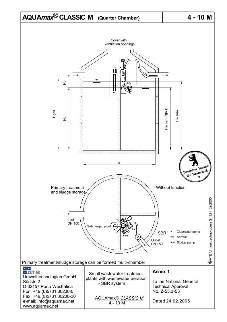
1.1 Object of the approval are small wastewater treatment plants, with wastewater aeration, made from concrete for installation in the ground, which are operated as activated sludge plants with storage function in various sizes for 4 to 53 I in accordance with Annex 1.
Small wastewater treatment plants with wastewater aeration serve for the aerobic biological treatment of domestic wastewater collected using the separate system and commercial wastewater in so far as it is comparable with domestic wastewater.
The small wastewater treatment plants, including all components, are basically produced as new plants. They can, however, also be produced through appropriate retrofitting of existing plants.
The approval of essential modifications to an existing wastewater treatment system (retrofitting of existing multi-chamber cesspits) takes place in accordance with national legal provisions within the framework of the legal water authorisation process.
1.2 The following may not be discharged to the small wastewater treatment plant: - commercial wastewater so far as it is not comparable with domestic wastewater - infiltration water (e.g. drainage water) - cooling water - water discharged from swimming pools - precipitation water
1.3 With this National General Technical Approval, in addition to the general technical requirements, the requirements under water law within the meaning of the ordinances of the German Federal States for the determination of the suitability of construction products and types of structure are met through verification in accordance with the German Federal State Building Regulations (German WasBauPVO).
1.4 The National General Technical Approval is granted irrespective of test or approval limiting conditions of other legal areas (e.g. 1st Ordinance to the [German] Equipment Safety Law - Low Voltage Directive -, [German] Law on the Electromagnetic Compatibility of Equipment – EMVG Directive -, 11th Ordinance of the [German] Equipment Safety Law – Explosion Protection Ordinance -, 9th Ordinance to the [German] Equipment Safety Law – Machinery Directive).
2 Provisions for the construction product
2.1 Characteristics and requirements 2.1.1 Characteristics
The small wastewater treatment plants with wastewater aeration (activated sludge plants operated with storage function) in accordance with the functional description in Annex 23 have been tested on a test field in accordance with prEN 12566-31 and assessed according to the approval principles for small wastewater treatment plants of the German Institute for Structural Engineering. Small wastewater treatment plants of this type are in a position to fulfil the following requirements in on-site operation.
_________________________ 1 prEN 12566-3:10-2001 “Small wastewater treatment plants for up to 50 PT, Part 3: prefabricated and/or on-
site assembled plants for the treatment of domestic wastewater”.

Page 4 of the National General Technical Approval No. Z-55.3-53 dated 24 February 2005
Requirements determined at the outlet of the small wastewater treatment plant (Discharge Class D):
- BOD5: ≤ 15 mg/l from a 24 h composite sample, homogenised
≤ 20 mg/l from a random sample, homogenised
- COD: ≤ 75 mg/l from a 24 h composite sample, homogenised
≤ 90 mg/l from a random sample, homogenised
- NH4-N: ≤ 10 mg/l from a 24 h composite sample, filtered
- Ninorg: ≤ 25 mg/l from a 24 h composite sample, filtered
- Filterable solids: ≤ 50 mg/l from a random sample 2.1.2 Requirements 2.1.2.1 The wastewater engineering dimensioning for each design capacity is to be taken
from the tables in Annexes 3, 6, 8, 9, 11, 13, 16 and 22. 2.1.2.2 Structure of small wastewater treatment plants Small wastewater treatment plants, with regard to design, materials used and
dimensions must correspond with the details of Annexes 1 to 22. For the retrofitting of existing plants the details in Annexes 17 to 22 are relevant.
2.1.2.3 Verification of stability DIN 10452 applies for the verification of stability. The verification of stability is to be provided through a static calculation in the individual case or through a static-type testing by the manufacturer. The necessary verifications are to be furnished for both the greatest as well as for the smallest installation depth. The horizontal earth pressure is to be applied uniformly for all types of soil as Ph = 0.5 γ x h, whereby 20 kN/m3 is to be assumed for γ.
2.2 Production, certification
2.2.1 Production
2.2.1.1 General Small wastewater treatment plants are produced either completely in the factory or
through retrofitting of existing plants. 2.2.1.2 Concrete components are to be employed which correspond with the [German]
Building Control List A, Part 1, Serial No. 1.6.1 and have the following characteristics. - The concrete for small wastewater treatment plants must correspond with at
least B45. - The concrete must also meet the requirements of standard specification DIN
42813. - The concrete components must have the laiddown dimensions and be
reinforced in accordance with the static calculation. Concrete components must be certified in accordance with the provisions of the technical regulations according to [German] Building Control List A, Part 1, Serial No. 1.6.1 using the construction supervisory conformity mark. The certification must also contain the above-given characteristics required for the intended use. Para. 1 is dispensed with if the concrete components are part of an existing plant with construction supervisory verification of suitability.
_________________________ 2 DIN 1045:1988-07 “Concrete and reinforced concrete, design and construction”
3 DIN 4281:1998-08 “Concrete for factory produced drainage objects: production, testing and monitoring” [Not available in English]

Page 5 of the National General Technical Approval No. Z-55.3-53 dated 24 February 2005
2.2.2 Certification Small wastewater treatment plants with wastewater aeration (activated sludge plants
operating with storage function) must be certified by the manufacturer using the conformity mark in accordance with the [German] Conformity Mark Ordinance of the [German] Federal States. Certification may only take place if the prerequisites in accordance with Section 2.3 are met. In addition, small wastewater treatment plants with wastewater aeration are to be marked clearly and permanently with the following details:
- Type designation - Max. I
- Electrical connected load - Usable volumes of the sludge storage
of the buffer of the activated sludge tank
- Discharge Class D
2.3 Certificate of conformity 2.3.1 New construction 2.3.1.1 General The confirmation of the conformity of small sewage treatment plants with
wastewater aeration with the provisions of this National General Technical Approval must take place for each manufacturing plant by means of a declaration of conformity by the manufacturer based on a factory production control.
2.3.1.2 Factory production control In each manufacturing plant a factory production control is to be established and
carried out. “Factory production control” is understood to mean the continuous production monitoring carried out by the manufacturer, by means of which he ensures that the construction products he has manufactured conform to the provisions of this National General Technical Approval.
The factory production control consists of: - Description and examination of the original material and of the components:
The conformity of the materials delivered with the provisions of this National General Technical Approval is at least to be verified by the supplier by means of certificates of conformity in accordance with EN 102044, Point 2.1 and the delivery papers are to be checked for each delivery and for agreement with the order.
The concrete components must be certified in accordance with the provisions of the technical rules from the German] Building Control List A, Part 1, Serial No. 1.6.1 using the construction supervisory conformity mark. The certification must also contain the required essential characteristics for the intended use in accordance with Section 2.2.1.1.
- Checks and examinations which are to be carried out on the finished product are: To establish and check for conformity with the statements in the Annexes of
this National General Technical Approval
• the relevant dimensions of the component
• the diameter and the arrangement of inlet and outlet by height
• installation depth and height above the water level of the submerged pipe and scum board
___________________________ 4 EN 10204:1995-08 “Metallic products; types of inspection documents”

Page 6 of the National General Technical Approval No. Z-55.3-53 dated 24 February 2005
- Testing of watertightness of each first component after start of production, and thereafter each 100th component in accordance with DIN 4261-1015. However, at least one control per week is to be carried out.
The results of the factory production control are to be recorded and evaluated. The documents are to contain at least the following information:
- designation of the construction product and/or of the original material and its constituents
- type of check or examination
- date of production and of the examination of the construction product and/or the original material or the constituents
- result of checks and examinations, as far as applicable, comparison with the requirements
- signature of the person responsible for the factory production control.
The records are to be kept for least five years. They are to be submitted, on demand, to the Deutsches Institut für Bautechnik, the responsible highest building supervisory authority or the responsible water authority.
If the test result is unsatisfactory, the manufacturer is, without delay, to take the necessary measures to remedy the fault. Construction products which do not meet the requirements are to be handled in such a way that they cannot be confused with those that meet the requirements. After rectification of the fault the respective examination is to be repeated immediately as far as it is technically feasible and necessary to verify correction of the fault.
2.3.2 Retrofitting
The confirmation of conformity of the retrofitted plant with the provisions of the National General Technical Approval must take place using a declaration of conformity of the firm carrying out the retrofit on the basis of the following checks of the plant which is installed ready on site:
The completeness of the assembled plant and the arrangement of the plant components including the installation depth are to be verified.
The results of checks and examinations are to be recorded and evaluated. The records must contain at least the following details:
- designation of the plant or the tank including mounting parts - type of check or examination - date of check and examination - results of checks and examinations and, as far as applicable, comparison with
the requirements - signature of those responsible for the checks With unsatisfactory results the necessary measures for the rectification of the fault
are to be taken without delay by the firming carrying out the retrofit. Following correction of the fault the appropriate test is to be repeated without delay – as far as technically possible and necessary for verification of the correction of the fault.
The recording of checks and examinations as well the conformity certification are to be kept for at least five years by the customer and the installing firm. They are to be submitted, on demand, to the Deutsches Institut für Bautechnik, the responsible highest building supervisory authority or the responsible water authority.
_________________________ 5 DIN 4261-101:1998-02 “Small wastewater treatment plants, plants without wastewater aeration, principles
for factory production control and outside monitoring” [Not available in English]
Page 7 of the National General Technical Approval No. Z-55.3-53 dated 24 February 2005
3 Provisions for installation
3.1 Installation instruction The applicant has to produce an individual installation instruction each both for the case that the small wastewater treatment plant was produced completely in the factory and for the case that it was produced through retrofitting of an existing plant. Here the provisions of Annexes 24 and 25 are to be observed.
3.2 Plants produced completely in the factory
Installation is to be carried out in accordance with the manufacturer’s installation instruction taking into account the constraints, which are base on the stability verification. In accordance with DIN 4261-26:1984-06, Point 4.2.4, watertightness is to be verified following installation of the complete plant including connection of the connecting pipelines.
3.3 Plant produced through retrofitting of an existing plant
Installation is to be carried out in accordance with the manufacturer’s installation instruction Following emptying the correct condition of the existing multi-chamber cesspit is to be assessed and documented by visual inspection under the responsibility of the firm carrying out the retrofit. Possible subsequent tasks are to be carried out and recorded in writing by this firm taking into account installed and/or converted items. This is to be passed to the operator together with the operating logbook. All structural modifications on existing multi-chamber cesspits such as the closure of access openings, arrangement of transitions between the chambers and others must take place according to the graphical documentation of this National General Technical Approval. The structural modifications may not prejudice the static concept of the plants of this National General Technical Approval.
The thus modified plant must at least correspond with the details of the plants of this National General Technical Approval. In accordance with DIN 4261-27:1984-06, Point 4.2.4, watertightness is to be verified following modification of the complete plant including connection of the connecting pipelines.
4 Provisions for use, operation and maintenance
4.1 General The characteristics confirmed under Section 2.1.1 are achievable in on-site
operation only if operation and maintenance are carried out according to the following provisions.
Small wastewater treatment plants must always be ready for operation. Small wastewater treatment plants must be equipped with a mains-independent
power failure monitoring system. Only such wastewater is permitted to be fed to small wastewater treatment plants
that neither damages these nor disrupts their function (see DIN 1986-38). __________________________ 6 DIN 4261-2:06-1984: “Small sewage treatment plants; plants with sewage aeration; application, design,
construction and testing” 7 DIN 4261-2:06-1984 “Small sewage treatment plants; plants with sewage aeration; application, design,
construction and testing” 8 DIN 1986-3: “Drainage and sewerage systems for buildings and plots of land; rules for service
and maintenance”
Page 8 of the National General Technical Approval No. Z-55.3-53 dated 24 February 2005
The manufacturer of the plant is to draw up an instruction for operation and maintenance, including sludge removal, which at least contains the provisions of this National General Technical Approval, and is to hand this to the operator of the plant.
All parts of the plant which require regular maintenance, must be accessible in safety at any time .
Operation and maintenance are to be arranged in such a way that
- hazards to the environment are not to be expected, which applies in particular for the removal, transport and disposal of sludge from small wastewater treatment plants
- small wastewater treatment plants are not prejudiced or endangered in their stability and in their function in accordance with the intended use
- the body of water intended for the discharge of the treated wastewater is not loaded beyond the permitted degree or otherwise changed in a detrimental way
- no persistent annoying odours occur.
Particular care is to be taken if the small wastewater treatment plant has to be entered for repair or maintenance purposes. The appropriate accident prevention regulations are to be observed.
4.2 Use
The number of inhabitants whose wastewater may respectively as a maximum be fed to small wastewater treatment plants (max I) depends on the details in Annexes 1 to 22 of this National General Technical Approval.
4.3 Operation 4.3.1 General
The operator must allow tasks to be carried out by a competent9 person if he himself does not posses the required technical expertise.
When the plant is taken into service, the operator is to receive instruction from the applicant or from an expert. The instruction is to be certified.
The operator is to carry out at regular intervals all tasks which mainly comprise the functional check of the plant as well as, if required, the measurement and of the most important operational parameters; here the operating instructions are to be observed.
4.3.2 Daily checks It is to be checked whether the plant is in operation. 4.3.4 Monthly checks The following checks are to be carried out:
- visual inspection of the effluent for sludge discharge - check of the inlet and outlet for blockages visual inspection) - determination of the possible presence of floating sludge and, if required,
removal of the floating sludge (in the sludge storage) - reading of the operating hours meter of the aerator and the pumps and recording
in the operator’s log. Faults or problems detected are to be remedied immediately by the operator or by a
tasked specialist and are to be recorded in the operator’s log. _________________________ 9 As “competent” are seen: operator’s personnel or tasked third persons who, due to their training, their knowledge
and their experience obtained through practical activity, guarantee that they carry out self-monitoring on small wastewater treatment plants correctly.
Page 9 of the National General Technical Approval No. Z-55.3-53 dated 24 February 2005
4.3 Maintenance
Maintenance is to be carried out at least twice a year (at intervals of ca. six months) by the applicant or a specialist company (specialist)10.
Maintenance comprises the following:
- inspection of the operator’s log with determination of regular operation (variance comparison)
- functional check of the mechanical, electrical and other plant components which are essential for operation, in particular of the blower, of the pumps and of the mammoth pump. Maintenance of these plant components in accordance with manufacturer’s details
- functional check of the control system and the alarm function
- setting of optimal operating values such as oxygen supply and sludge volume component
- examination of the sludge height in the primary settling stage /sludge storage. If necessary, arrangement of the sludge removal by the operator. For a correct operation of the small wastewater treatment plant a sludge disposal which meets the requirement is required. Sludge removal is to be arranged at the latest with 70 % filling of the sludge storage with sludge
- execution of general cleaning tasks, e.g. removal of deposits - check of structural condition of the plant - check of sufficient aeration and ventilation - maintenance carried out is to be noted in the operator’ log. Investigations in the aeration tank: - oxygen concentration - sludge volume component.
A random sample of the effluent is to be taken within the scope of maintenance. With this the following values are to be examined:
- - temperature - pH value - settleable solids - COD - NH4-N - Ninorg Findings and tasks carried out are to be recorded in a maintenance report. The
maintenance report is to be given to the operator. The operator is to include the maintenance report in the operator’s log and to submit the latter on demand to the responsible supervisory building authority or the responsible water authority.
Herold
Certified
_______________________ 10 Specialist firms are operator-independent firms whose staff (specialists), due to their professional training and their
participation in relevant qualification measures, possess the necessary qualification for operation and maintenance of small wastewater treatment plants.


© A
TB
Um
wel
ttech
nolo
gien
Gm
bH, 0
2/20
05
The listed volumes and heights determine the minimum dimensions and, in practice, can be larger. Non-listed diameters are to be interpolated.
Symbols and units: AR m2 Surface area of the SB Reactor (SBR) AS m2 Surface area of the sludge storage Bd kg/d BOD5 load / day [ = 0.06 kg BOD5 / PT x d] d m Diameter PT Total number of inhabitants and population equivalents HW,max m Maximum height of water in the SBR [> 1.0 m] HW,min m Minimum height of water in the SBR HS m Minimum water level in the coarse interceptor / sludge storage [M: > HW,min; Z: > 0.8 m] HB m Height of the buffer in the sludge storage Htot m Min. depth of water from lower edge of inlet pipe to upper edge of tank bottom [= HS + HB] Qd m3/d Wastewater inflow / day Q10 m3/h Max. wastewater inflow / hour VdZ m3 Quantity of wastewater / cycle [= 3 cycles / day] VR,mean,nec m3 Mean reactor volume [= Bd / BR with a volumetric loading [BR] of 0.2 kg/(m3xd] VR,mean m3 Actual mean reactor volume VR,max m3 Maximum reactor volume [= VR,mean + VdZ/2]. If this volume corresponds to a water
depth hw,max < 1.0 m the volume is to be adjusted in order to achieve a hW, max > 1.0 m. VR,min m3 Minimum reactor volume VS m3 Volume of the sludge storage [> 0.25 m3 / PT] VS,tot m3 Minimum useful volume of the sludge storage [= VS + VP] VB m3 Volume of the buffer [= 4h* x Q10]** [* maximum charging-free time ** + 0.2 m3 bath water surge with 4, 6, 8 PT]
AQUAmax® BASIC / Classic M Installation in quarter chamber
PT Diam.
Qd VdZ Bd Q10 d AR AS
VR, mittel,
erf VR, max VR, min VR, mittel VS VP VS, ges HW, max HW, min HS HP Hges
[m³/d] [m³] [kg/d] [m³/h] [m]4 0,60 0,20 0,24 0,06 2,00 0,73 1,51 1,20 1,30 1,10 1,20 2,28 0,44 2,72 1,78 1,51 1,51 0,29 1,804 0,60 0,20 0,24 0,06 2,30 0,98 2,02 1,20 1,30 1,10 1,20 2,27 0,44 2,71 1,33 1,12 1,12 0,22 1,344 0,60 0,20 0,24 0,06 2,50 1,17 2,39 1,20 1,30 1,10 1,20 2,25 0,44 2,69 1,11 0,94 0,94 0,18 1,124 0,60 0,20 0,24 0,06 2,80 1,39 2,79 1,20 1,39 1,19 1,29 2,39 0,44 2,83 1,00 0,86 0,86 0,16 1,016 0,90 0,30 0,36 0,09 2,30 0,98 2,02 1,80 1,95 1,65 1,80 3,40 0,56 3,96 1,99 1,68 1,68 0,28 1,996 0,90 0,30 0,36 0,09 2,50 1,17 2,39 1,80 1,95 1,65 1,80 3,37 0,56 3,93 1,67 1,41 1,41 0,23 1,676 0,90 0,30 0,36 0,09 2,80 1,39 2,79 1,80 1,95 1,65 1,80 3,31 0,56 3,87 1,40 1,19 1,19 0,20 1,406 0,90 0,30 0,36 0,09 3,00 1,70 3,46 1,80 1,95 1,65 1,80 3,36 0,56 3,92 1,15 0,97 0,97 0,16 1,158 1,20 0,40 0,48 0,12 2,80 1,39 2,79 2,40 2,60 2,20 2,40 4,42 0,48 4,90 1,87 1,58 1,58 0,17 1,878 1,20 0,40 0,48 0,12 3,00 1,70 3,46 2,40 2,60 2,20 2,40 4,48 0,48 4,96 1,53 1,29 1,29 0,14 1,53
10 1,50 0,50 0,60 0,15 3,00 1,70 3,46 3,00 3,25 2,75 3,00 5,60 0,60 6,20 1,91 1,62 1,62 0,17 1,91
Heights [m]Inflow
[m²]
Volumes [m³]Surface
Umwelttechnologien GmbH Südstr. 2 32457 Porta Westfalica Fon: +49.(0)5731.30230-0 Fax: +49.(0)5731.30230-30 e-mail: [email protected] www.aquamax.net
Small wastewater treatment plants with wastewater aeration – SBR system
Parameters
Annex 3
To the National General Technical Approval No. Z-55.3-53
Dated 24.02.2005


© A
TB
Um
wel
ttech
nolo
gien
Gm
bH, 0
2/20
05
The listed volumes and heights determine the minimum dimensions and, in practice, can be larger. Non-listed diameters are to be interpolated
Symbols and units: AR m2 Surface area of the SB Reactor (SBR) AS m2 Surface area of the sludge storage Bd kg/d BOD5 load / day [ = 0.06 kg BOD5 / PT x d] d m Diameter PT Total number of inhabitants and population equivalents HW,max m Maximum height of water in the SBR [> 1.0 m] HW,min m Minimum height of water in the SBR HS m Minimum water level in the coarse interceptor / sludge storage [M: > HW,min; Z: > 0.8 m] HB m Height of the buffer in the sludge storage Htot m Min. depth of water from lower edge of inlet pipe to upper edge of tank bottom [= HS + HB] Qd m3/d Wastewater inflow / day Q10 m3/h Max. wastewater inflow / hour VdZ m3 Quantity of wastewater / cycle [= 3 cycles / day] VR,mean,nec m3 Mean reactor volume [= Bd / BR with a volumetric loading [BR] of 0.2 kg/(m3xd] VR,mean m3 Actual mean reactor volume VR,max m3 Maximum reactor volume [= VR,mean + VdZ/2]. If this volume corresponds to a water depth
hw,max < 1.0 m the volume is to be adjusted in order to achieve a hW, max > 1.0 m. VR,min m3 Minimum reactor volume VS m3 Volume of the sludge storage [> 0.25 m3 / PT] VS,tot m3 Minimum useful volume of the sludge storage [= VS + VP] VB m3 Volume of the buffer [= 4h* x Q10]** [* maximum charging-free time ** + 0.2 m3 bath water surge with 4, 6, 8 PT]
AQUAmax® BASIC / Classic M Installation in half chamberPT Diam.
Qd VdZ Bd Q10 d AR AS
VR, mittel,
erf. VR, max VR, min VR, mittel VS VP VS, ges HW, max HW, min HS HP Hges
[m³/d] [m³] [kg/d] [m³/h] [m]4 0,60 0,20 0,24 0,06 2,00 1,51 1,46 1,20 1,51 1,31 1,41 1,27 0,44 1,71 1,00 0,87 0,87 0,30 1,174 0,60 0,20 0,24 0,06 2,30 2,02 1,96 1,20 2,02 1,82 1,92 1,77 0,44 2,21 1,00 0,90 0,90 0,22 1,134 0,60 0,20 0,24 0,06 2,50 2,39 2,33 1,20 2,39 2,19 2,29 2,14 0,44 2,58 1,00 0,92 0,92 0,19 1,116 0,90 0,30 0,36 0,09 2,00 1,51 1,46 1,80 1,95 1,65 1,80 1,60 0,56 2,16 1,29 1,09 1,09 0,38 1,486 0,90 0,30 0,36 0,09 2,30 2,02 1,96 1,80 2,02 1,72 1,87 1,67 0,56 2,23 1,00 0,85 0,85 0,29 1,146 0,90 0,30 0,36 0,09 2,50 2,39 2,33 1,80 2,39 2,09 2,24 2,04 0,56 2,60 1,00 0,87 0,87 0,24 1,118 1,20 0,40 0,48 0,12 2,00 1,51 1,46 2,40 2,60 2,20 2,40 2,13 0,68 2,81 1,72 1,46 1,46 0,47 1,928 1,20 0,40 0,48 0,12 2,30 2,02 1,96 2,40 2,60 2,20 2,40 2,13 0,68 2,81 1,29 1,09 1,09 0,35 1,448 1,20 0,40 0,48 0,12 2,50 2,39 2,33 2,40 2,60 2,20 2,40 2,14 0,68 2,82 1,09 0,92 0,92 0,29 1,218 1,20 0,40 0,48 0,12 2,80 2,92 2,79 2,40 2,92 2,52 2,72 2,41 0,68 3,09 1,00 0,86 0,86 0,24 1,1112 1,80 0,60 0,72 0,18 2,30 2,02 1,96 3,60 3,90 3,30 3,60 3,20 0,72 3,92 1,93 1,63 1,63 0,37 2,0012 1,80 0,60 0,72 0,18 2,50 2,39 2,33 3,60 3,90 3,30 3,60 3,22 0,72 3,94 1,63 1,38 1,38 0,31 1,6912 1,80 0,60 0,72 0,18 2,80 2,92 2,79 3,60 3,90 3,30 3,60 3,15 0,72 3,87 1,34 1,13 1,13 0,26 1,3912 1,80 0,60 0,72 0,18 3,00 3,46 3,39 3,60 3,90 3,30 3,60 3,23 0,72 3,95 1,13 0,95 0,95 0,21 1,1716 2,40 0,80 0,96 0,24 2,50 2,39 2,33 4,80 5,20 4,40 4,80 4,29 0,96 5,25 2,18 1,84 1,84 0,41 2,2516 2,40 0,80 0,96 0,24 2,80 2,92 2,79 4,80 5,20 4,40 4,80 4,20 0,96 5,16 1,78 1,51 1,51 0,34 1,8516 2,40 0,80 0,96 0,24 3,00 3,46 3,39 4,80 5,20 4,40 4,80 4,31 0,96 5,27 1,50 1,27 1,27 0,28 1,5520 3,00 1,00 1,20 0,30 2,80 2,92 2,79 6,00 6,50 5,50 6,00 5,26 1,20 6,46 2,23 1,88 1,88 0,43 2,3120 3,00 1,00 1,20 0,30 3,00 3,46 3,39 6,00 6,50 5,50 6,00 5,39 1,20 6,59 1,88 1,59 1,59 0,35 1,94
Heights [m]Inflow
[m²]
Volumes [m³]Surface
Umwelttechnologien GmbH Südstr. 2 32457 Porta Westfalica Fon: +49.(0)5731.30230-0 Fax: +49.(0)5731.30230-30 e-mail: [email protected] www.aquamax.net
Small wastewater treatment plants with wastewater aeration – SBR system
Parameters
Annex 6
To the National General Technical Approval No. Z-55.3-53
Dated 24.02.2005


AQUAmax® Classic Z Multi tank type in concretePT
Qd VdZ Bd Q10 d1 d2 d3 AS AR
VR,
mittel, erf VR, max VR, min VR, mittel, VS VP VS, ges HW, max HW, min HS HP Hges
[m³/d] [m³] [kg/d] [m³/h]4 0,60 0,20 0,24 0,06 1,00 1,00 0,79 0,79 1,20 1,30 1,10 1,20 1,00 0,44 1,44 1,66 1,40 1,27 0,56 1,834 0,60 0,20 0,24 0,06 1,20 1,00 1,13 0,79 1,20 1,30 1,10 1,20 1,00 0,44 1,44 1,66 1,40 0,88 0,39 1,274 0,60 0,20 0,24 0,06 1,20 1,20 1,13 1,13 1,20 1,30 1,10 1,20 1,00 0,44 1,44 1,15 0,97 0,88 0,39 1,274 0,60 0,20 0,24 0,06 1,50 1,00 1,77 0,79 1,20 1,30 1,10 1,20 1,41 0,44 1,85 1,66 1,40 0,80 0,25 1,054 0,60 0,20 0,24 0,06 1,50 1,20 1,77 1,13 1,20 1,30 1,10 1,20 1,41 0,44 1,85 1,15 0,97 0,80 0,25 1,054 0,60 0,20 0,24 0,06 1,50 1,50 1,77 1,77 1,20 1,77 1,57 1,67 1,41 0,44 1,85 1,00 0,89 0,80 0,25 1,054 0,60 0,20 0,24 0,06 2,00 1,00 3,14 0,79 1,20 1,30 1,10 1,20 2,51 0,44 2,95 1,66 1,40 0,80 0,14 0,944 0,60 0,20 0,24 0,06 2,00 1,20 3,14 1,13 1,20 1,30 1,10 1,20 2,51 0,44 2,95 1,15 0,97 0,80 0,14 0,944 0,60 0,20 0,24 0,06 2,00 1,50 3,14 1,77 1,20 1,77 1,57 1,67 2,51 0,44 2,95 1,00 0,89 0,80 0,14 0,946 0,90 0,30 0,36 0,09 1,20 1,20 1,13 1,13 1,80 1,95 1,65 1,80 1,50 0,56 2,06 1,73 1,46 1,33 0,50 1,826 0,90 0,30 0,36 0,09 1,50 1,20 1,77 1,13 1,80 1,95 1,65 1,80 1,50 0,56 2,06 1,73 1,46 0,85 0,32 1,176 0,90 0,30 0,36 0,09 1,50 1,50 1,77 1,77 1,80 1,95 1,65 1,80 1,50 0,56 2,06 1,10 0,93 0,85 0,32 1,176 0,90 0,30 0,36 0,09 2,00 1,50 3,14 1,77 1,80 1,95 1,65 1,80 2,51 0,56 3,07 1,10 0,93 0,80 0,18 0,986 0,90 0,30 0,36 0,09 2,00 2,00 3,14 3,14 1,80 3,14 2,84 2,99 2,51 0,56 3,07 1,00 0,90 0,80 0,18 0,988 1,20 0,40 0,48 0,12 1,50 1,50 1,77 1,77 2,40 2,60 2,20 2,40 2,00 0,68 2,68 1,47 1,25 1,13 0,38 1,528 1,20 0,40 0,48 0,12 2,00 1,50 3,14 1,77 2,40 2,60 2,20 2,40 2,51 0,68 3,19 1,47 1,25 0,80 0,22 1,028 1,20 0,40 0,48 0,12 2,00 2,00 3,14 3,14 2,40 3,14 2,74 2,94 2,51 0,68 3,19 1,00 0,87 0,80 0,22 1,028 1,20 0,40 0,48 0,12 1,00 1,20 2,00 1,92 3,14 2,40 3,14 2,74 2,94 2,00 0,68 2,68 1,00 0,87 1,04 0,36 1,4010 1,50 0,50 0,60 0,15 1,50 1,50 1,77 1,77 3,00 3,25 2,75 3,00 2,50 0,60 3,10 1,84 1,56 1,42 0,34 1,7610 1,50 0,50 0,60 0,15 2,00 1,50 3,14 1,77 3,00 3,25 2,75 3,00 2,51 0,60 3,11 1,84 1,56 0,80 0,19 0,9910 1,50 0,50 0,60 0,15 2,00 2,00 3,14 3,14 3,00 3,25 2,75 3,00 2,51 0,60 3,11 1,04 0,88 0,80 0,19 0,9910 1,50 0,50 0,60 0,15 2,30 2,30 4,15 4,15 3,00 4,15 3,65 3,90 3,32 0,60 3,92 1,00 0,88 0,80 0,14 0,9410 1,50 0,50 0,60 0,15 2,50 2,50 4,91 4,91 3,00 4,91 4,41 4,66 3,93 0,60 4,53 1,00 0,90 0,80 0,12 0,9210 1,50 0,50 0,60 0,15 2,50 2,00 4,91 3,14 3,00 3,25 2,75 3,00 3,93 0,60 4,53 1,04 0,88 0,80 0,12 0,9210 1,50 0,50 0,60 0,15 1,20 1,20 2,00 2,26 3,14 3,00 3,25 2,75 3,00 2,50 0,60 3,10 1,04 0,88 1,11 0,27 1,3710 1,50 0,50 0,60 0,15 1,50 1,50 2,00 3,53 3,14 3,00 3,25 2,75 3,00 2,83 0,60 3,43 1,04 0,88 0,80 0,17 0,9712 1,80 0,60 0,72 0,18 1,20 1,20 2,00 2,26 3,14 3,60 3,90 3,30 3,60 3,00 0,72 3,72 1,24 1,05 1,33 0,32 1,6512 1,80 0,60 0,72 0,18 1,50 1,50 2,00 3,53 3,14 3,60 3,90 3,30 3,60 3,00 0,72 3,72 1,24 1,05 0,85 0,20 1,0512 1,80 0,60 0,72 0,18 2,00 2,00 3,14 3,14 3,60 3,90 3,30 3,60 3,00 0,72 3,72 1,24 1,05 0,96 0,23 1,1812 1,80 0,60 0,72 0,18 2,50 2,00 4,91 3,14 3,60 3,90 3,30 3,60 3,93 0,72 4,65 1,24 1,05 0,80 0,15 0,9512 1,80 0,60 0,72 0,18 2,30 2,30 4,15 4,15 3,60 4,15 3,55 3,85 3,32 0,72 4,04 1,00 0,86 0,80 0,17 0,9712 1,80 0,60 0,72 0,18 2,50 2,50 4,91 4,91 3,60 4,91 4,31 4,61 3,93 0,72 4,65 1,00 0,88 0,80 0,15 0,9516 2,40 0,80 0,96 0,24 1,50 1,50 2,00 3,53 3,14 4,80 5,20 4,40 4,80 4,00 0,96 4,96 1,66 1,40 1,13 0,27 1,4016 2,40 0,80 0,96 0,24 1,50 2,00 2,50 4,91 4,91 4,80 5,20 4,40 4,80 4,00 0,96 4,96 1,06 0,90 0,82 0,20 1,0116 2,40 0,80 0,96 0,24 2,00 2,00 3,14 3,14 4,80 5,20 4,40 4,80 4,00 0,96 4,96 1,66 1,40 1,27 0,31 1,5816 2,40 0,80 0,96 0,24 2,50 2,00 4,91 3,14 4,80 5,20 4,40 4,80 4,00 0,96 4,96 1,66 1,40 0,82 0,20 1,0116 2,40 0,80 0,96 0,24 2,30 2,30 4,15 4,15 4,80 5,20 4,40 4,80 4,00 0,96 4,96 1,25 1,06 0,96 0,23 1,1916 2,40 0,80 0,96 0,24 2,50 2,50 4,91 4,91 4,80 5,20 4,40 4,80 4,00 0,96 4,96 1,06 0,90 0,82 0,20 1,0120 3,00 1,00 1,20 0,30 1,50 1,50 2,00 3,53 3,14 6,00 6,50 5,50 6,00 5,00 1,20 6,20 2,07 1,75 1,42 0,34 1,7620 3,00 1,00 1,20 0,30 1,50 2,00 2,50 4,91 4,91 6,00 6,50 5,50 6,00 5,00 1,20 6,20 1,32 1,12 1,02 0,24 1,2620 3,00 1,00 1,20 0,30 2,00 2,00 3,14 3,14 6,00 6,50 5,50 6,00 5,00 1,20 6,20 2,07 1,75 1,59 0,38 1,9720 3,00 1,00 1,20 0,30 2,50 2,00 4,91 3,14 6,00 6,50 5,50 6,00 5,00 1,20 6,20 2,07 1,75 1,02 0,24 1,2620 3,00 1,00 1,20 0,30 2,30 2,30 4,15 4,15 6,00 6,50 5,50 6,00 5,00 1,20 6,20 1,57 1,32 1,20 0,29 1,4920 3,00 1,00 1,20 0,30 2,50 2,50 4,91 4,91 6,00 6,50 5,50 6,00 5,00 1,20 6,20 1,32 1,12 1,02 0,24 1,2620 3,00 1,00 1,20 0,30 2,80 2,80 6,15 6,15 6,00 6,50 5,50 6,00 5,00 1,20 6,20 1,06 0,89 0,81 0,19 1,0120 3,00 1,00 1,20 0,30 2,00 2,00 2,50 6,28 4,91 6,00 6,50 5,50 6,00 5,02 1,20 6,22 1,32 1,12 0,80 0,19 0,99
[m²]
Inflow Heights [m]Surface Volumes [m³]Diam.
[m]
© A
TB
U
mw
eltte
chno
logi
en
Gm
bH, 0
2/20
05
The listed volumes and heights determine the minimum dimensions and, in practice, can be larger. Non-listed diameters are to be interpolated.
Umwelttechnologien GmbH Südstr. 2 32457 Porta Westfalica Fon: +49.(0)5731.30230-0 Fax: +49.(0)5731.30230-30 e-mail: [email protected] www.aquamax.net
Small wastewater treatment plants with wastewater aeration – SBR system
Parameters
Annex 8
To the National General Technical Approval No. Z-55.3-53
Dated 24.02.2005

AQUAmax® Classic Z Multi tank type in concretePT
Qd VdZ Bd Q10 d1 d2 d3 AS AR
VR,
mittel, erf VR, max VR, min VR, mittel VS VP VS, ges HW, max HW, min HS HP Hges
[m³/d] [m³] [kg/d] [m³/h]24 3,60 1,20 1,44 0,36 2,30 2,30 4,15 4,15 7,20 7,80 6,60 7,20 6,00 1,44 7,44 1,88 1,59 1,44 0,35 1,7924 3,60 1,20 1,44 0,36 2,50 2,50 4,91 4,91 7,20 7,80 6,60 7,20 6,00 1,44 7,44 1,59 1,35 1,22 0,29 1,5224 3,60 1,20 1,44 0,36 1,50 2,00 2,50 4,91 4,91 7,20 7,80 6,60 7,20 6,00 1,44 7,44 1,59 1,35 1,22 0,29 1,5224 3,60 1,20 1,44 0,36 2,00 2,00 2,50 6,28 4,91 7,20 7,80 6,60 7,20 6,00 1,44 7,44 1,59 1,35 0,96 0,23 1,1824 3,60 1,20 1,44 0,36 2,30 2,30 2,80 8,31 6,15 7,20 7,80 6,60 7,20 6,64 1,44 8,08 1,27 1,07 0,80 0,17 0,9724 3,60 1,20 1,44 0,36 2,50 2,50 3,00 9,81 7,07 7,20 7,80 6,60 7,20 7,85 1,44 9,29 1,10 0,93 0,80 0,15 0,9524 3,60 1,20 1,44 0,36 2,80 2,80 6,15 6,15 7,20 7,80 6,60 7,20 6,00 1,44 7,44 1,27 1,07 0,97 0,23 1,2124 3,60 1,20 1,44 0,36 3,00 3,00 7,07 7,07 7,20 7,80 6,60 7,20 6,00 1,44 7,44 1,10 0,93 0,85 0,20 1,0528 4,20 1,40 1,68 0,42 2,30 2,30 4,15 4,15 8,40 9,10 7,70 8,40 7,00 1,68 8,68 2,19 1,85 1,69 0,40 2,0928 4,20 1,40 1,68 0,42 2,50 2,50 4,91 4,91 8,40 9,10 7,70 8,40 7,00 1,68 8,68 1,85 1,57 1,43 0,34 1,7728 4,20 1,40 1,68 0,42 1,50 2,00 2,50 4,91 4,91 8,40 9,10 7,70 8,40 7,00 1,68 8,68 1,85 1,57 1,43 0,34 1,7728 4,20 1,40 1,68 0,42 2,00 2,00 2,50 6,28 4,91 8,40 9,10 7,70 8,40 7,00 1,68 8,68 1,85 1,57 1,11 0,27 1,3828 4,20 1,40 1,68 0,42 2,30 2,30 2,80 8,31 6,15 8,40 9,10 7,70 8,40 7,00 1,68 8,68 1,48 1,25 0,84 0,20 1,0528 4,20 1,40 1,68 0,42 2,50 2,50 3,00 9,81 7,07 8,40 9,10 7,70 8,40 7,85 1,68 9,53 1,29 1,09 0,80 0,17 0,9728 4,20 1,40 1,68 0,42 2,80 2,80 6,15 6,15 8,40 9,10 7,70 8,40 7,00 1,68 8,68 1,48 1,25 1,14 0,27 1,4128 4,20 1,40 1,68 0,42 3,00 3,00 7,07 7,07 8,40 9,10 7,70 8,40 7,00 1,68 8,68 1,29 1,09 0,99 0,24 1,2332 4,80 1,60 1,92 0,48 2,50 2,50 4,91 4,91 9,60 10,40 8,80 9,60 8,00 1,92 9,92 2,12 1,79 1,63 0,39 2,0232 4,80 1,60 1,92 0,48 2,00 2,00 2,50 6,28 4,91 9,60 10,40 8,80 9,60 8,00 1,92 9,92 2,12 1,79 1,27 0,31 1,5832 4,80 1,60 1,92 0,48 2,30 2,30 2,80 8,31 6,15 9,60 10,40 8,80 9,60 8,00 1,92 9,92 1,69 1,43 0,96 0,23 1,1932 4,80 1,60 1,92 0,48 2,50 2,50 3,00 9,81 7,07 9,60 10,40 8,80 9,60 8,00 1,92 9,92 1,47 1,25 0,82 0,20 1,0132 4,80 1,60 1,92 0,48 2,80 2,80 6,15 6,15 9,60 10,40 8,80 9,60 8,00 1,92 9,92 1,69 1,43 1,30 0,31 1,6132 4,80 1,60 1,92 0,48 3,00 3,00 7,07 7,07 9,60 10,40 8,80 9,60 8,00 1,92 9,92 1,47 1,25 1,13 0,27 1,4036 5,40 1,80 2,16 0,54 2,30 2,30 2,80 8,31 6,15 10,80 11,70 9,90 10,80 9,00 2,16 11,16 1,90 1,61 1,08 0,26 1,3436 5,40 1,80 2,16 0,54 2,50 2,50 3,00 9,81 7,07 10,80 11,70 9,90 10,80 9,00 2,16 11,16 1,66 1,40 0,92 0,22 1,1436 5,40 1,80 2,16 0,54 2,80 2,80 6,15 6,15 10,80 11,70 9,90 10,80 9,00 2,16 11,16 1,90 1,61 1,46 0,35 1,8136 5,40 1,80 2,16 0,54 3,00 3,00 7,07 7,07 10,80 11,70 9,90 10,80 9,00 2,16 11,16 1,66 1,40 1,27 0,31 1,5840 6,00 2,00 2,40 0,60 2,50 2,50 3,00 9,81 7,07 12,00 13,00 11,00 12,00 10,00 2,40 12,40 1,84 1,56 1,02 0,24 1,2640 6,00 2,00 2,40 0,60 2,80 2,80 6,15 6,15 12,00 13,00 11,00 12,00 10,00 2,40 12,40 2,11 1,79 1,62 0,39 2,0140 6,00 2,00 2,40 0,60 3,00 3,00 7,07 7,07 12,00 13,00 11,00 12,00 10,00 2,40 12,40 1,84 1,56 1,42 0,34 1,7644 6,60 2,20 2,64 0,66 2,50 2,50 3,00 9,81 7,07 13,20 14,30 12,10 13,20 11,00 2,64 13,64 2,02 1,71 1,12 0,27 1,3944 6,60 2,20 2,64 0,66 3,00 3,00 7,07 7,07 13,20 14,30 12,10 13,20 11,00 2,64 13,64 2,02 1,71 1,56 0,37 1,9348 7,20 2,40 2,88 0,72 2,50 2,50 3,00 9,81 7,07 14,40 15,60 13,20 14,40 12,00 2,88 14,88 2,21 1,87 1,22 0,29 1,5248 7,20 2,40 2,88 0,72 3,00 3,00 7,07 7,07 14,40 15,60 13,20 14,40 12,00 2,88 14,88 2,21 1,87 1,70 0,41 2,1153 7,95 2,65 3,18 0,80 2,50 2,50 3,00 9,81 7,07 15,90 17,23 14,58 15,90 13,25 3,18 16,43 2,44 2,06 1,35 0,32 1,6753 7,95 2,65 3,18 0,80 3,00 3,00 7,07 7,07 15,90 17,23 14,58 15,90 13,25 3,18 16,43 2,44 2,06 1,88 0,45 2,33
[m²]
Inflow Heights [m]Surface Volumes [m³]Diam.
[m]
© A
TB
U
mw
eltte
chno
logi
en
Gm
bH, 0
2/20
05
The listed volumes and heights determine the minimum dimensions and, in practice, can be larger. Non-listed diameters are to be interpolated
Umwelttechnologien GmbH Südstr. 2 32457 Porta Westfalica Fon: +49.(0)5731.30230-0 Fax: +49.(0)5731.30230-30 e-mail: [email protected] www.aquamax.net
Small wastewater treatment plants with wastewater aeration – SBR system
Parameters
Annex 9
To the National General Technical Approval No. Z-55.3-53
Dated 24.02.2005


AQUAmax® Classic Z Multi-tank type in concrete, two-lanePT
Qd VdZ Bd Q10 d1 d22 x d3 AS AR
VR,
mittel, erf VR, max VR, min VR, mittel VS VP VS, ges HW, max HW, min HS HP Hges
[m³/d] [m³] [kg/d] [m³/h]36 5,40 1,80 2,16 0,54 2,30 2,30 2,30 8,31 8,31 10,80 11,70 9,90 10,80 9,00 2,16 11,16 1,41 1,19 1,08 0,26 1,3436 5,40 1,80 2,16 0,54 2,50 2,50 2,50 9,81 9,81 10,80 11,70 9,90 10,80 9,00 2,16 11,16 1,19 1,01 0,92 0,22 1,1440 6,00 2,00 2,40 0,60 2,30 2,30 2,30 8,31 8,31 12,00 13,00 11,00 12,00 10,00 2,40 12,40 1,57 1,32 1,20 0,29 1,4940 6,00 2,00 2,40 0,60 2,50 2,50 2,50 9,81 9,81 12,00 13,00 11,00 12,00 10,00 2,40 12,40 1,32 1,12 1,02 0,24 1,2644 6,60 2,20 2,64 0,66 2,30 2,30 2,30 8,31 8,31 13,20 14,30 12,10 13,20 11,00 2,64 13,64 1,72 1,46 1,32 0,32 1,6444 6,60 2,20 2,64 0,66 2,50 2,50 2,50 9,81 9,81 13,20 14,30 12,10 13,20 11,00 2,64 13,64 1,46 1,23 1,12 0,27 1,3944 6,60 2,20 2,64 0,66 2,80 2,80 2,80 12,31 12,31 13,20 14,30 12,10 13,20 11,00 2,64 13,64 1,16 0,98 0,89 0,21 1,1148 7,20 2,40 2,88 0,72 2,30 2,30 2,30 8,31 8,31 14,40 15,60 13,20 14,40 12,00 2,88 14,88 1,88 1,59 1,44 0,35 1,7948 7,20 2,40 2,88 0,72 2,50 2,50 2,50 9,81 9,81 14,40 15,60 13,20 14,40 12,00 2,88 14,88 1,59 1,35 1,22 0,29 1,5248 7,20 2,40 2,88 0,72 2,80 2,80 2,80 12,31 12,31 14,40 15,60 13,20 14,40 12,00 2,88 14,88 1,27 1,07 0,97 0,23 1,2153 7,95 2,65 3,18 0,80 2,30 2,30 2,30 8,31 8,31 15,90 17,23 14,58 15,90 13,25 3,18 16,43 2,07 1,75 1,60 0,38 1,9853 7,95 2,65 3,18 0,80 2,50 2,50 2,50 9,81 9,81 15,90 17,23 14,58 15,90 13,25 3,18 16,43 1,76 1,49 1,35 0,32 1,6753 7,95 2,65 3,18 0,80 2,80 2,80 2,80 12,31 12,31 15,90 17,23 14,58 15,90 13,25 3,18 16,43 1,40 1,18 1,08 0,26 1,33
[m²]
Inflow Heights [m]Surface Volumes [m³]Diam.
[m]
© A
TB
U
mw
eltte
chno
logi
en
Gm
bH, 0
2/20
05
The listed volumes and heights determine the minimum dimensions and, in practice, can be larger. Non-listed diameters are to be interpolated.
Umwelttechnologien GmbH Südstr. 2 32457 Porta Westfalica Fon: +49.(0)5731.30230-0 Fax: +49.(0)5731.30230-30 e-mail: [email protected] www.aquamax.net
Small wastewater treatment plants with wastewater aeration – SBR system
Parameters
Annex 11
To the National General Technical Approval No. Z-55.3-53
Dated 24.02.2005


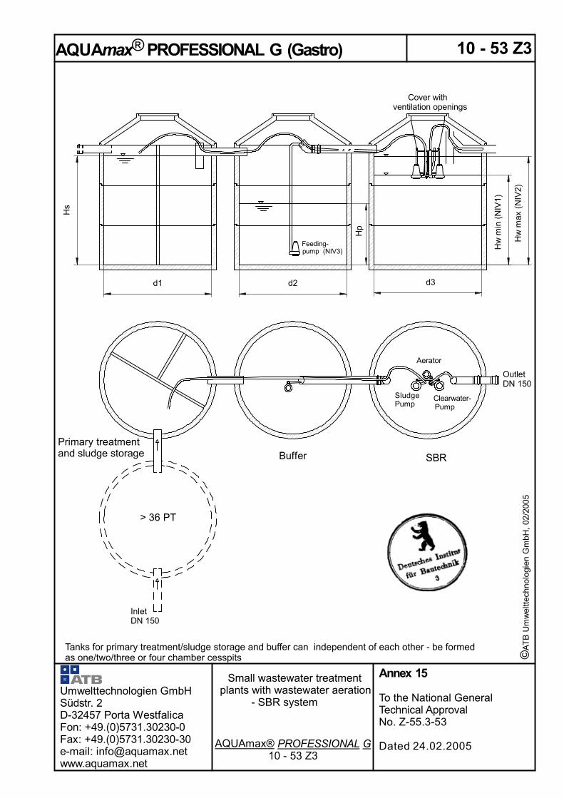
AQUAmax® PROFESSIONAL GM (Gastro) Three-chamber cesspit in concretePT
Q d V dZ B d Q 10 d A P A S A R V R, mittel V R, max V R, min VS,erf * V S VP * H W, max H W, min H S HP *[m³/d] [m³] [kg/d] [m³/h] [m] < H W, max
4 0,60 0,20 0,24 0,06 2,00 0,73 1,51 0,73 1,20 1,30 1,10 1,00 2,64 0,44 1,78 1,51 1,75 0,604 0,60 0,20 0,24 0,06 2,30 0,98 2,02 0,98 1,20 1,30 1,10 1,00 2,63 0,44 1,33 1,12 1,30 0,454 0,60 0,20 0,24 0,06 2,50 1,16 2,39 1,16 1,20 1,30 1,10 1,00 2,63 0,44 1,12 0,95 1,10 0,386 0,90 0,30 0,36 0,09 2,50 1,16 2,39 1,16 1,80 1,95 1,65 1,50 3,82 0,56 1,68 1,42 1,60 0,486 0,90 0,30 0,36 0,09 2,80 1,40 2,92 1,40 1,80 1,95 1,65 1,50 3,80 0,56 1,39 1,18 1,30 0,406 0,90 0,30 0,36 0,09 3,00 1,70 3,46 1,70 1,80 1,95 1,65 1,50 3,81 0,56 1,15 0,97 1,10 0,338 1,20 0,40 0,48 0,12 2,50 1,16 2,39 1,16 2,40 2,60 2,20 2,00 5,26 0,68 2,24 1,90 2,20 0,598 1,20 0,40 0,48 0,12 2,80 1,40 2,92 1,40 2,40 2,60 2,20 2,00 5,26 0,68 1,86 1,57 1,80 0,498 1,20 0,40 0,48 0,12 3,00 1,70 3,46 1,70 2,40 2,60 2,20 2,00 5,19 0,68 1,53 1,29 1,50 0,4010 1,50 0,50 0,60 0,15 3,00 1,70 3,46 1,70 3,00 3,25 2,75 2,50 6,23 0,60 1,91 1,62 1,80 0,35
[m²]
Heights [m]Inflow Volumes [m³]Diam. Surface
© A
TB
Um
wel
ttech
nolo
gien
Gm
bH, 0
2/20
05
* Minimum volumes and/or heights. These can be considerably larger depending on application case.The listed volumes and heights determine the minimum dimensions and, in practice, can be larger. Non-listed diameters are to be interpolated
Symbols and units: AP m2 Surface area of the buffer AR m2 Surface area of the SB Reactor (SBR) AS m2 Surface area of the sludge storage Bd kg/d BOD5 load / day [ = 0.06 kg BOD5 / PT x d] d m Diameter PT Total number of inhabitants and population equivalents HW,max m Maximum height of water in the SBR [> 1.0 m] HW,min m Minimum height of water in the SBR HS m Minimum water level in the coarse interceptor / sludge storage [M: > HW,min; Z: > 0.8 m] HB m Height of the buffer in the sludge storage Htot m Min. depth of water from lower edge of inlet pipe to upper edge of tank bottom [= HS + HB] Qd m3/d Wastewater inflow / day Q10 m3/h Max. wastewater inflow / hour VdZ m3 Quantity of wastewater / cycle [= 3 cycles / day] VR,mean m3 Mean reactor volume [= Bd / BR with a volumetric loading [BR] of 0.2 kg/(m3xd] VR,max m3 Maximum reactor volume [= VR,mean + VdZ/2]. If this volume corresponds to a water depth
hw,max < 1.0 m the volume is to be adjusted in order to achieve a hW, max > 1.0 m. VR,min m3 Minimum reactor volume VS,nec m3 Volume of the sludge storage [> 0.25 m3 / PT] VS m3 Actual volume of sludge storage VB m3 Volume of the buffer [= 4h* x Q10]** [* maximum charging-free time ** + 0.2 m3 bath water surge with 4, 6, 8 PT]
Umwelttechnologien GmbH Südstr. 2 32457 Porta Westfalica Fon: +49.(0)5731.30230-0 Fax: +49.(0)5731.30230-30 e-mail: [email protected] www.aquamax.net
Small wastewater treatment plants with wastewater aeration – SBR system
Parameters
Annex 13
To the National General Technical Approval No. Z-55.3-53
Dated 24.02.2005


AQUAmax® PROFESSIONAL GZ (Gastro) Multi-tank type in concretePT
Qd VdZ Bd Q10 d1 d2 d3 AP AS AR VR, mittel VR, max VR, min VS VP* HW, max HW, min HS HP*[m³/d] [m³] [kg/d] [m³/h]
Z/P-26 0,90 0,30 0,36 0,09 2,00 1,50 - 1,57 1,57 1,77 1,80 1,95 1,65 1,50 0,56 1,10 0,93 0,96 0,368 1,20 0,40 0,48 0,12 2,00 1,50 - 1,57 1,57 1,77 2,40 2,60 2,20 2,00 0,68 1,47 1,25 1,27 0,4310 1,50 0,50 0,60 0,15 2,00 1,50 - 1,57 1,57 1,77 3,00 3,25 2,75 2,50 0,60 1,84 1,56 1,59 0,3810 1,50 0,50 0,60 0,15 2,00 2,00 - 1,57 1,57 3,14 3,00 3,25 2,75 2,50 0,60 1,04 0,88 1,59 0,3812 1,80 0,60 0,72 0,18 2,00 2,00 - 1,57 1,57 3,14 3,60 3,90 3,30 3,00 0,72 1,24 1,05 1,91 0,4612 1,80 0,60 0,72 0,18 2,30 2,30 - 2,08 2,08 4,15 3,60 4,15 3,55 3,00 0,72 1,00 0,86 1,44 0,3512 1,80 0,60 0,72 0,18 2,50 2,00 - 2,45 2,45 3,14 3,60 3,90 3,30 3,00 0,72 1,24 1,05 1,22 0,2916 2,40 0,80 0,96 0,24 2,30 2,00 - 2,08 2,08 3,14 4,80 5,20 4,40 4,00 0,96 1,66 1,40 1,93 0,4616 2,40 0,80 0,96 0,24 2,30 2,30 - 2,08 2,08 4,15 4,80 5,20 4,40 4,00 0,96 1,25 1,06 1,93 0,4616 2,40 0,80 0,96 0,24 2,50 2,00 - 2,45 2,45 3,14 4,80 5,20 4,40 4,00 0,96 1,66 1,40 1,63 0,3920 3,00 1,00 1,20 0,30 2,50 2,00 - 2,45 2,45 3,14 6,00 6,50 5,50 5,00 1,20 2,07 1,75 2,04 0,4920 3,00 1,00 1,20 0,30 2,50 2,30 - 2,45 2,45 4,15 6,00 6,50 5,50 5,00 1,20 1,57 1,32 2,04 0,4920 3,00 1,00 1,20 0,30 2,50 2,50 - 2,45 2,45 4,91 6,00 6,50 5,50 5,00 1,20 1,32 1,12 2,04 0,4920 3,00 1,00 1,20 0,30 2,80 2,30 - 3,08 3,08 4,15 6,00 6,50 5,50 5,00 1,20 1,57 1,32 1,62 0,3920 3,00 1,00 1,20 0,30 2,80 2,50 - 3,08 3,08 4,91 6,00 6,50 5,50 5,00 1,20 1,32 1,12 1,62 0,3924 3,60 1,20 1,44 0,36 2,80 2,50 - 3,08 3,08 4,91 7,20 7,80 6,60 6,00 1,44 1,59 1,35 1,95 0,47
Z/P-310 1,50 0,50 0,60 0,15 1,50 ** 1,50 ** 1,77 1,77 3,00 3,25 2,75 2,50 0,60 1,84 1,56 1,42 **10 1,50 0,50 0,60 0,15 2,00 ** 2,00 ** 3,14 3,14 3,00 3,25 2,75 2,51 0,60 1,04 0,88 0,80 **12 1,80 0,60 0,72 0,18 2,00 ** 2,00 ** 3,14 3,14 3,60 3,90 3,30 3,00 0,72 1,24 1,05 0,96 **16 2,40 0,80 0,96 0,24 2,00 ** 2,00 ** 3,14 3,14 4,80 5,20 4,40 4,00 0,96 1,66 1,40 1,27 **16 2,40 0,80 0,96 0,24 2,30 ** 2,30 ** 4,15 4,15 4,80 5,20 4,40 4,00 0,96 1,25 1,06 0,96 **20 3,00 1,00 1,20 0,30 2,00 ** 2,00 ** 3,14 3,14 6,00 6,50 5,50 5,00 1,20 2,07 1,75 1,59 **20 3,00 1,00 1,20 0,30 2,30 ** 2,30 ** 4,15 4,15 6,00 6,50 5,50 5,00 1,20 1,57 1,32 1,20 **20 3,00 1,00 1,20 0,30 2,50 ** 2,50 ** 4,91 4,91 6,00 6,50 5,50 5,00 1,20 1,32 1,12 1,02 **24 3,60 1,20 1,44 0,36 2,30 ** 2,30 ** 4,15 4,15 7,20 7,80 6,60 6,00 1,44 1,88 1,59 1,44 **24 3,60 1,20 1,44 0,36 2,50 ** 2,50 ** 4,91 4,91 7,20 7,80 6,60 6,00 1,44 1,59 1,35 1,22 **28 4,20 1,40 1,68 0,42 2,30 ** 2,30 ** 4,15 4,15 8,40 9,10 7,70 7,00 1,68 2,19 1,85 1,69 **28 4,20 1,40 1,68 0,42 2,50 ** 2,50 ** 4,91 4,91 8,40 9,10 7,70 7,00 1,68 1,85 1,57 1,43 **28 4,20 1,40 1,68 0,42 2,80 ** 2,80 ** 6,15 6,15 8,40 9,10 7,70 7,00 1,68 1,48 1,25 1,14 **36 5,40 1,80 2,16 0,54 2,80 ** 2,80 ** 6,15 6,15 10,80 11,70 9,90 9,00 2,16 1,90 1,61 1,46 **36 5,40 1,80 2,16 0,54 3,00 ** 3,00 ** 7,07 7,07 10,80 11,70 9,90 9,00 2,16 1,66 1,40 1,27 **44 6,60 2,20 2,64 0,66 2 x 2,00 ** 3,00 ** 6,28 7,07 13,20 14,30 12,10 11,00 2,64 2,02 1,71 1,75 **53 7,95 2,65 3,18 0,80 2 x 2,50 ** 3,00 ** 9,82 7,07 15,90 17,23 14,58 13,25 3,18 2,44 2,06 1,35 **
Inflow Diam.
[m] [m²]
Volumes [m³] Heights [m]Surface
© A
TB
Um
wel
ttech
nolo
gien
Gm
bH, 0
2/20
05
* Minimum volumes and/or heights. These can be considerably larger depending on application case. ** Depending on the application case and the amount of wastewater produced. The required buffer volume
can be considerably above the minimum volume given under VB. It requires a separate technical wastewater calculation and is to be verified in every individual case.
The listed volumes and heights determine the minimum dimensions and, in practice, can be larger. Non-listed diameters are to be interpolated.
Umwelttechnologien GmbH Südstr. 2 32457 Porta Westfalica Fon: +49.(0)5731.30230-0 Fax: +49.(0)5731.30230-30 e-mail: [email protected] www.aquamax.net
Small wastewater treatment plants with wastewater aeration – SBR system
Parameters
Annex 16
To the National General Technical Approval No. Z-55.3-53
Dated 24.02.2005


* AQUAmax M. HS > HW,min; AQUAmax Z: HS > 0.8 m. The listed volumes and heights determine the minimum dimensions and, in practice, can be larger. If the volume of the primary settling stage > 425 l/PT one can reckon with a pollution load of 40 g BOD5 (/PT x d) in the inlet to the activated sludge stage.
Umwelttechnologien GmbH Südstr. 2 32457 Porta Westfalica Fon: +49.(0)5731.30230-0 Fax: +49.(0)5731.30230-30 e-mail: [email protected] www.aquamax.net
Small wastewater treatment plants with wastewater aeration – SBR system
Parameters
Annex 22
To the National General Technical Approval No. Z-55.3-53
Dated 24.02.2005
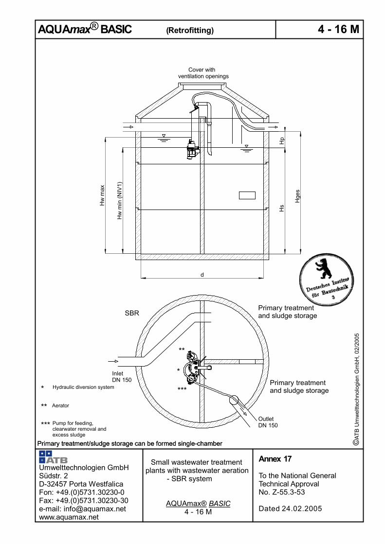
AQUAmax® BASIC / Classic Retrofitting
E 4 6 8 10 12 16 20 24 28 36 E 12 16 20 24 28 36 44 53Qd=0,15xE [m³/d] 0,60 0,90 1,20 1,50 1,80 2,40 3,00 3,60 4,20 5,40 Qd=0,15xE [m³/d] 1,80 2,40 3,00 3,60 4,20 5,40 6,60 7,95QdZ=Qd/3 [m³] 0,20 0,30 0,40 0,50 0,60 0,80 1,00 1,20 1,40 1,80 QdZ=Qd/3 [m³] 0,60 0,80 1,00 1,20 1,40 1,80 2,20 2,65Q10 0,06 0,09 0,12 0,15 0,18 0,24 0,30 0,36 0,42 0,54 Q10 0,18 0,24 0,30 0,36 0,42 0,54 0,66 0,80Bd=0,06xE [kg BSB5/d] 0,24 0,36 0,48 0,60 0,72 0,96 1,20 1,44 1,68 2,16 Bd=0,06xE [kg BSB5/d] 0,72 0,96 1,20 1,44 1,68 2,16 2,64 3,18VR, mittel=Bd/0,2 [m³] 1,20 1,80 2,40 3,00 3,60 4,80 6,00 7,20 8,40 10,80 VR, mittel=Bd/0,2 [m³] 3,60 4,80 6,00 7,20 8,40 10,80 13,20 15,90VRmax=VR, mittel+QSZ/2 [m³] 1,30 1,95 2,60 3,25 3,90 5,20 6,50 7,80 9,10 11,70 VRmax=VR, mittel+QSZ/2 [m³] 3,90 5,20 6,50 7,80 9,10 11,70 14,30 17,23VRmin=VRmax-QSZ [m³] 1,10 1,65 2,20 2,75 3,30 4,40 5,50 6,60 7,70 9,90 VRmin=VRmax-QSZ [m³] 3,30 4,40 5,50 6,60 7,70 9,90 12,10 14,58VS=0,25 x EW 1,00 1,50 2,00 2,50 3,00 4,00 5,00 6,00 7,00 9,00 VS=0,25 x EW 3,00 4,00 5,00 6,00 7,00 9,00 11,00 13,25VP=4 x Q10 0,44 0,56 0,68 0,60 0,72 0,96 1,20 1,44 1,68 2,16 VP=4 x Q10 0,72 0,96 1,20 1,44 1,68 2,16 2,64 3,18VS, ges=VS+VP 1,44 2,06 2,68 3,10 3,72 4,96 6,20 7,44 8,68 11,16 VS, ges=VS+VP 3,72 4,96 6,20 7,44 8,68 11,16 13,64 16,43
AR = AS = 1 m² AR = AS = 4,5 m²HWmax=VRmax/AR [m] 1,30 1,95 HWmax=VRmax/AR [m] 1,00 1,16 1,44 1,73 2,02HWmin=VRmin/AR [m] 1,10 1,65 HWmin=VRmin/AR [m] 0,87 0,98 1,22 1,47 1,71HP=VP/AS 0,44 0,56 HP=VP/AS 0,16 0,21 0,27 0,32 0,37HS=VS/AS* 1,00 1,50 HS=VS/AS* 0,80 0,89 1,11 1,33 1,56
H ges =H S +H P 1,44 2,06 H ges =H S +H P 0,96 1,10 1,38 1,65 1,93
AR = AS = 1,5 m² AR = AS = 5 m²HWmax=VRmax/AR [m] 1,00 1,30 1,73 2,17 HWmax=VRmax/AR [m] 1,04 1,30 1,56 1,82HWmin=VRmin/AR [m] 0,87 1,10 1,47 1,83 HWmin=VRmin/AR [m] 0,88 1,10 1,32 1,54HP=VP/AS 0,29 0,37 0,45 0,40 HP=VP/AS 0,19 0,24 0,29 0,34HS=VS/AS* 0,80 1,00 1,33 1,67 HS=VS/AS* 0,80 1,00 1,20 1,40
H ges =H S +H P 1,09 1,37 1,79 2,07 H ges =H S +H P 0,99 1,24 1,49 1,74
AR = AS = 2 m² AR = AS = 6 m²HWmax=VRmax/AR [m] 1,00 1,30 1,63 1,95 HWmax=VRmax/AR [m] 1,00 1,08 1,30 1,52 1,95HWmin=VRmin/AR [m] 0,85 1,10 1,38 1,65 HWmin=VRmin/AR [m] 0,87 0,92 1,10 1,28 1,65HP=VP/AS 0,28 0,34 0,30 0,36 HP=VP/AS 0,16 0,20 0,24 0,28 0,36HS=VS/AS* 0,80 1,00 1,25 1,50 HS=VS/AS* 0,80 0,83 1,00 1,17 1,50
H ges =H S +H P 1,08 1,34 1,55 1,86 H ges =H S +H P 0,96 1,03 1,24 1,45 1,86
AR = AS = 2,5 m² AR = AS = 7 m²HWmax=VRmax/AR [m] 1,04 1,30 1,56 2,08 HWmax=VRmax/AR [m] 1,00 1,11 1,30 1,67 2,04HWmin=VRmin/AR [m] 0,88 1,10 1,32 1,76 HWmin=VRmin/AR [m] 0,86 0,94 1,10 1,41 1,73HP=VP/AS 0,27 0,24 0,29 0,38 HP=VP/AS 0,17 0,21 0,24 0,31 0,38HS=VS/AS* 0,80 1,00 1,20 1,60 HS=VS/AS* 0,80 0,86 1,00 1,29 1,57
H ges =H S +H P 1,07 1,24 1,49 1,98 H ges =H S +H P 0,97 1,06 1,24 1,59 1,95
AR = AS = 3 m² AR = AS = 8 m²HWmax=VRmax/AR [m] 1,00 1,08 1,30 1,73 2,17 HWmax=VRmax/AR [m] 1,00 1,14 1,46 1,79 2,15HWmin=VRmin/AR [m] 0,87 0,92 1,10 1,47 1,83 HWmin=VRmin/AR [m] 0,85 0,96 1,24 1,51 1,82HP=VP/AS 0,23 0,20 0,24 0,32 0,40 HP=VP/AS 0,18 0,21 0,27 0,33 0,40HS=VS/AS* 0,80 0,83 1,00 1,33 1,67 HS=VS/AS* 0,80 0,88 1,13 1,38 1,66
H ges =H S +H P 1,03 1,03 1,24 1,65 2,07 H ges =H S +H P 0,98 1,09 1,40 1,71 2,05
AR = AS = 3,5 m² AR = AS = 9 m²HWmax=VRmax/AR [m] 1,00 1,11 1,49 1,86 HWmax=VRmax/AR [m] 1,01 1,30 1,59 1,91HWmin=VRmin/AR [m] 0,86 0,94 1,26 1,57 HWmin=VRmin/AR [m] 0,86 1,10 1,34 1,62HP=VP/AS 0,17 0,21 0,27 0,34 HP=VP/AS 0,19 0,24 0,29 0,35HS=VS/AS* 0,80 0,86 1,14 1,43 HS=VS/AS* 0,80 1,00 1,22 1,47
H ges =H S +H P 0,97 1,06 1,42 1,77 H ges =H S +H P 0,99 1,24 1,52 1,83
AR = AS = 4 m² AR = AS = 10 m²HWmax=VRmax/AR [m] 1,00 1,30 1,63 1,95 HWmax=VRmax/AR [m] 1,00 1,17 1,43 1,72HWmin=VRmin/AR [m] 0,85 1,10 1,38 1,65 HWmin=VRmin/AR [m] 0,86 0,99 1,21 1,46HP=VP/AS 0,18 0,24 0,30 0,36 HP=VP/AS 0,17 0,22 0,26 0,32HS=VS/AS* 0,80 1,00 1,25 1,50 HS=VS/AS* 0,80 0,90 1,10 1,33H ges =H S +H P 0,98 1,24 1,55 1,86 H ges =H S +H P 0,97 1,12 1,36 1,64
With deviating m3 numbers the values are to be interpolated!With rectangular construction the ratio of sides of the individual chambers are ca. 1:1 to 1:2!

Functional description AQUAmax
The wastewater treatment plant operates with a cycle time of ca. eight hours. Of these two hours are for the settling phase. Depending on the plant size, withdrawal of clarified water requires up to 20 minutes. During the six hour aeration phase oxygen is fed intermittently via a submerged aerator into the activated sludge tank. The plant has an upstream coarse interceptor which serves for the storage of the primary and secondary sludge and to buffer the inflowing water. The buffer can accept at least the maximum quantity of wastewater (Q10) inflowing in four hours. Four hours is the maximum time in which no wastewater may be fed into the SBR activated sludge stage (two hours before settling phase + two hours settling phase). The theoretical daily inflow volume is calculated for storage up to the lower edge of the inflow pipe. In emergencies the inflow pipe is available as sewer with storage capacity and overflow. With a back-up above the upper edge of the inlet pipe the inflowing water is removed via an emergency overflow. Charging of the activated sludge stage from the buffer takes place via a communicating pipe. This is filled, during the aeration phase, every two hours by a short stroke of the excess sludge pump. Subsequently the higher water level in the buffer is balanced with that of the activated sludge stage. Final charging takes place two hours before the settling phase. In order that, during the secondary settling phase, no untreated wastewater can flow in, air is fed into this communicating pipe. The flow of water from the buffer into the activated sludge stage is thus interrupted. Once per cycle the excess sludge is pumped into the coarse interceptor. The AQUAmax GASTRO has a separate buffer. If large quantities of wastewater are produced within a short period of time these can be retained in the separate buffer and fed to the SBR evenly and according to the wastewater treatment calculation using the charging pump. The activated sludge stage is also charged every two hours using a separate pump. Duration of charging depends on the size of the plant and is set at the control unit. The last charging takes place two hours before the settling stage. With the exceeding of the maximum water level (LEV 2) an alarm is activated via a float switch and charging is interrupted. Once per cycle the excess sludge is pumped into the coarse interceptor. During the settling phase the sludge components, which have entered the pump casing during the aeration phase, are washed out again using a patented process (flush surge) and settle in the SBR chamber. Following the settling phase the treated wastewater is pumped into the outlet until the switch-off point of the float (LEV 1). A possibility for taking a sample is to be planned!
The plant changes automatically into holiday operation if, six 6 hours after the start of the cycle the switch-on point of the float (LEV 1) is still not achieved. During holiday operation the aeration times are reduced to ca. 30 % of the normal aeration time. Charging continues to take place regularly. As soon as the switch-on point of the float is achieved the plant changes to normal operation. After two hours the settling stage starts. The plant is controlled by a PLC the settings of which can be changed via a code number. Error signals are indicated optically and acoustically. Operating hours, interventions and messages are automatically stored with date and time. An under voltage signal (UVS) is available as an option. With the AQUAmax BASIC charging, removal of excess sludge and drawing of clarified water is carried out using only one pump. The water flows here are fed into the individual areas using a patented hydraulic system. AQUAmax® PLUS Paket The AQUAmax® PLUS Paket is an optional extension to raise the cleaning performance. The plant is equipped with an optimized Software module. With an additional anoxic treatment phase the Total Nitrogen (Ntot) can be reduced below 25 mg/l (>12°C).
Umwelttechnologien GmbH Südstr. 2 32457 Porta Westfalica Fon: +49.(0)5731.30230-0 Fax: +49.(0)5731.30230-30 e-mail: [email protected] www.aquamax.net
Small wastewater treatment plants with wastewater aeration – SBR system
Parameters
Annex 23
To the National General Technical Approval No. Z-55.3-53
Dated 24.02.2005

© A
TB
U
mw
eltte
chno
logi
en
Gm
bH, 0
2/20
05
Installation Instructions AQUAmax BASIC / CLASSIC / PROFESSIONAL New Construction:
Requirements on the Customer:
- The tanks, manufactured in accordance with our specifications, are to be installed ready-made.
- A watertightness test must be carried out.
- At the start of assembly the aeration tank is to be free of wastewater and is to be clean.
- Inlets and outlets are to be made of KG (grey plastic) pipe DN 100 and extend inside by ca. 15 cm.
- The covers of the tanks must have openings for ventilation. If there is no ventilation via the covering, ventilation is to be provided in the inlet pipe directly in front of the coarse interceptor.
The control unit must be mounted at an appropriate position and be supplied with electricity (230 V).
A fuse-protected (FI residual current circuit breaker) cable 3 x 1.5 mm² is to be laid to the control unit. An empty pipe of at least DN 70 must be laid between the control unit and tank.
The connection of cables is to be carried out by a specialist firm!
Installation of the AQUAmax (will be carried out by us on instruction by the customer):
Hang the AQUAmax M (and BASIC) on the partition wall; attach AQUAmax Z from the cover support ring or conus using the chains.
The charging pipe must be fed into the coarse interceptor (AQUAmax CLASSIC M and BASIC). The riser of the excess sludge-charge pump must be connected with the hose and fed into the coarse interceptor. There it must be connected to the submerged pipe. (AQUAmax CLASSIC Z). With the AQUAmax PROFESSIONAL G (Gastro) the charging pump is to be mounted ca. 5 – 10 cm above the ground and the charging pipeline fed into the SBR chamber (free runoff!).
The discharge hose is secured to the sampling vessel by means of a pipe clip. With this, the hose may not dip into the water contained there. The hose must be fastened in the area of the chamber cover using a hose clamp.
Pull the connection cable of the AQUAmax through the empty pipe to the location of the control unit and screw on the plug to the appropriate point on the control unit. The plant must now be filled with water at least up to the point where the float switches off.
Connect the power line to the control system there after take the plant into service according to the commissioning menu (incl. test run). For the operation of the control unit please see separate instructions
The plant can be commissioned only when the coarse interceptor is filled.
Please note, with all connection work, that all cables and hoses are long enough in order that the AQUAmax can be removed from the facility without problem
Umwelttechnologien GmbH Südstr. 2 32457 Porta Westfalica Fon: +49.(0)5731.30230-0 Fax: +49.(0)5731.30230-30 e-mail: [email protected] www.aquamax.net
Small wastewater treatment plants with wastewater aeration – SBR system
Parameters
Annex 24
To the National General Technical Approval No. Z-55.3-53
Dated 24.02.2005

© A
TB
U
mw
eltte
chno
logi
en
Gm
bH, 0
2/20
05
Installation Instructions AQUAmax BASIC / CLASSIC / PROFESSIONAL Retrofit:
Requirements on the Customer:
- The structural condition of the plant and the tanks must be in order.
- Within the scope of a retrofit pipelines must be laid according to our details and existing slits and openings in the partition walls must be created or, if necessary, closed.
- A watertightness test must be carried out.
- At the start of assembly the aeration tank is to be free of wastewater and is to be clean.
- Inlets and outlets are to be made of KG pipe DN 100 and extend inside by ca. 15 cm.
- The covers of the tanks must have openings for ventilation. If there is no ventilation via the covering, ventilation is to be provided in the inlet pipe directly in front of the coarse interceptor.
The control unit must be mounted at an appropriate position and be supplied with electricity (230 V).
A fuse-protected (FI residual current circuit breaker) cable 3 x 1.5 mm² is to be laid to the control unit. An empty pipe of at least DN 70 must be laid between the control unit and tank.
The connection of cables is to be carried out by a specialist firm!
Installation of the AQUAmax (will be carried out by us on instruction by the customer):
Hang the AQUAmax M (and BASIC) on the partition wall; attach AQUAmax Z from the cover support ring or conus using the chains. The charging pipe must be fed into the coarse interceptor (AQUAmax CLASSIC M and BASIC). The riser of the excess sludge-charge pump must be connected with the hose and fed into the coarse interceptor. There it must be connected to the submerged pipe. (AQUAmax CLASSIC Z). With the AQUAmax PROFESSIONAL G (GASTRO) the charging pump is to be mounted ca. 5 – 10 cm above the ground and the charging pipeline fed into the SBR chamber (free runoff!).
The discharge hose is secured to the sampling vessel by means of a pipe clip. With this, the hose may not dip into the water contained there. The hose must be fastened in the area of the chamber cover using a hose clamp.
Pull the connection cable of the a through the empty pipe to the location of the control unit and screw on the plug to the appropriate point on the control unit. The plant must now be filled with water at least up to the point where the float switches off.
Connect the power line to the control system there after take the plant into service according to the commissioning menu (incl. test run). For the operation of the control unit please see separate instructions
The plant can be commissioned only when the coarse interceptor is filled.
Please note, with all connection work, that all cables and hoses are long enough in order that the AQUAmax can be removed from the facility without problem.
Umwelttechnologien GmbH Südstr. 2 32457 Porta Westfalica Fon: +49.(0)5731.30230-0 Fax: +49.(0)5731.30230-30 e-mail: [email protected] www.aquamax.net
Small wastewater treatment plants with wastewater aeration – SBR system
Parameters
Annex 25
To the National General Technical Approval No. Z-55.3-53
Dated 24.02.2005