37. Diagenesis of Silica, Zeolites, and Phyllosilicates at Sites 397 ...
Upload
truongdieuCategory
view
223download
1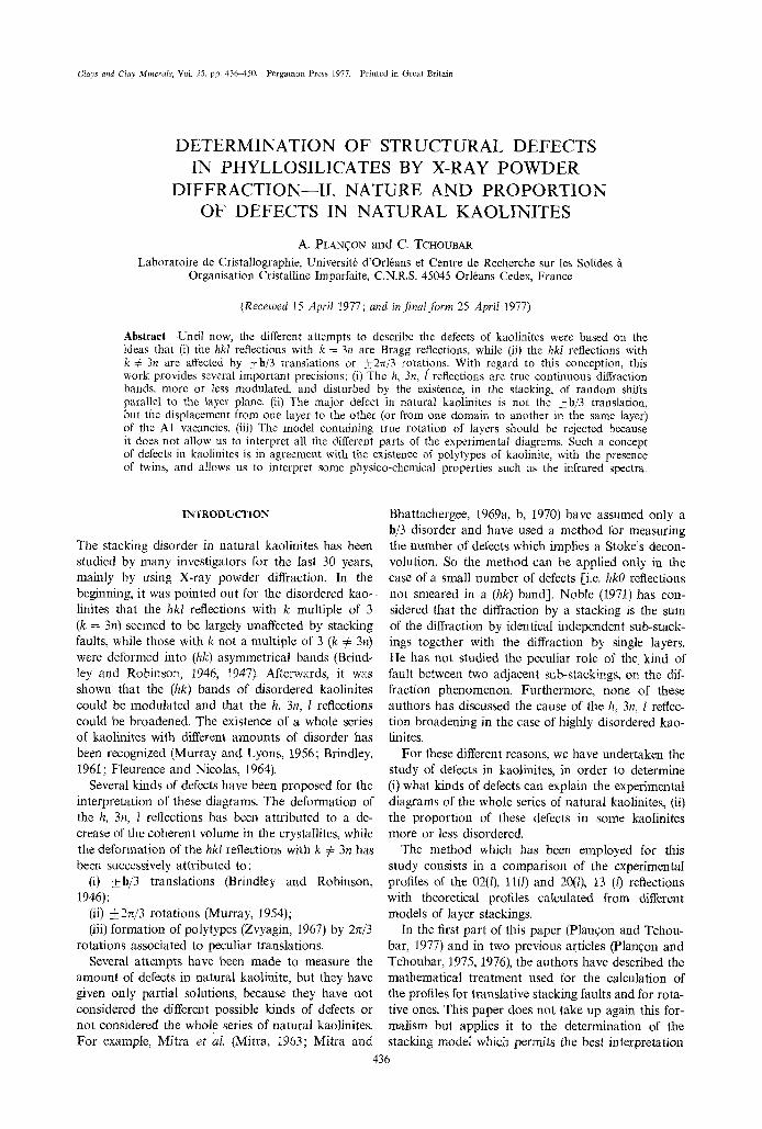
Clays and Clay Minerals, Vol. 25, pp. 436450. Pergamon Press 1977. Printed in Great Britain
DETERMINATION OF STRUCTURAL DEFECTS IN PHYLLOSILICATES BY X-RAY POWDER
DIFFRACTION--II. NATURE AND PROPORTION OF DEFECTS IN NATURAL KAOLINITES
A. PLAN•ON and C. TCHOUBAR
Laboratoire de Cristallographie, Universit6 d'Orltans et Centre de Recherche sur les Solides /t Organisation Cristalline Imparfaite, C.N.R.S. 45045 Orltans Cedex, France
(Received 15 April 1977; and in final form 25 April 1977)
Abstract--Until now, the different attempts to describe the defects of kaolinites were based on the ideas that (i) the hkl reflections with k = 3n are Bragg reflections, while (ii) the hkl reflections with k ~ 3n are affected by +h/3 translations or • rotations. With regard to this conception, this work provides several important precisions: (i) The h, 3n, [ reflections are true continuous diffraction bands, more or less modulated, and disturbed by the existence, in the stacking, of random shifts parallel to the layer plane. (ii) The major defect in natural kaolinites is not the ___b/3 translation, but the displacement from one layer to the other (or from one domain to another in the same layer) of the A1 vacancies. (iii) The model containing true rotation of layers should be rejected because it does not allow us to interpret all the different parts of the experimental diagrams. Such a concept of defects in kaolinites is in agreement with the existence of polytypes of kaolinite, with the presence of twins, and allows us to interpret some physico-chemical properties such as the infrared spectra.
INTRODUCTION
The stacking disorder in natural kaolinites has been studied by many investigators for the last 30 years, mainly by using X-ray powder diffraction. In the beginning, it was pointed out for the disordered kao- linites that the hkl reflections with k multiple of 3 (k = 3n) seemed to be largely unaffected by stacking faults, while those with k not a multiple of 3 (k 5~ 3n) were deformed into (hk) asymmetrical bands (Brind- ley and Robinson, 1946, t947). Aftelwvards, it was shown that the (hk) bands of disordered kaolinites could be modulated and that the h, 3n, l reflections could be broadened. The existence of a whole series of kaolinites with different amounts of disorder has been recognized (Murray and Lyons, 1956; Brindley, 1961; Fleurence and Nicolas, 1964).
Several kinds of defects have been proposed for the interpretation of these diagrams. The deformation of the h, 3n, l reflections has been attributed to a de- crease of the coherent volume in the crystallites, while the deformation of the hkl reflections with k 7~ 3n has been successively attributed to:
(i) _+b/3 translations (Brindley and Robinson, 1946);
(ii) ___2~/3 rotations (Murray, 1954); (iii) formation of polytypes (Zvyagin, 1967) by 2~/3
rotations associated to peculiar translations. Several attempts have been made to measure the
amount of defects in natural kaolinite, but they have given only partial solutions, because they have not considered the different possible kinds of defects or not considered the whole series of natural kaolinites. For example, Mitra et al. (Mitra, I963; Mitra and
Bhattachergee, 1969a, b, 1970) have assumed only a h/3 disorder and have used a method for measuring the number of defects which implies a Stoke's decon- volution. So the method can be applied only in the case of a small number of defects [i.e. hkO reflections not smeared in a (hk) band]. Noble (1971) has con- sidered that the diffraction by a stacking is the sum of the diffraction by identical independent sub-stack- ings together with the diffraction by single layers. He has not studied the peculiar role of the kind of fault between two adjacent sub-stackings, on the dif- fraction phenomenon. Furthermore, none of these authors has discussed the cause of the h, 3n, l reflec- tion broadening in the case of highly disordered kao- linites.
For these different reasons, we have undertaken the study of defects in kaolinites, in order to determine (i) what kinds of defects can explain the experimental diagrams of the whole series of natural kaolinites, (ii) the proportion of these defects in some kaolinites more or less disordered.
The method which has been employed for this study consists in a comparison of the experimental profiles of the 02(l), 11(l) and 20(0, 13 (l) reflections with theoretical profiles calculated from different models of layer stackings.
In the first part of this paper (Plangon and Tchou- bar, 1977) and in two previous articles (Plangon and Tchoubar, 1975, 1976), the authors have described the mathematical treatment used for the calculation of the profiles for translative stacking faults and for rota- tive ones. This paper does not take up again this for- realism but applies it to the determination of the stacking model which permits the best interpretation
436
Defects in phyllosilicates by X-ray diffraction--II 437
of the experimental powder patterns of the whole series of natural kaolinites.
EXPERIMENTAL
Recordin 9 of the experimental patterns
The method of work being a comparison between theoretical and experimental profiles, it is necessary to obtain well-defined recordings. The transmission diffraction method allows a correct evaluation of the experimental deformations in the range of small dif- fraction angles. The influence of the irradiated thick- ness and of the beam absorption are well defined (Croche, 1976) and the aberrations coming from the sample roughness are suppressed. We have used a C.G.R. diffractometer, where the flat sample is verti- cal. The kaolinite powder is kept between two poly- styrene sheets (thickness: 0.03mm). The K~I radi- ation of Cu is isolated by a quartz monochromator which gives a linear focus. The 2/2 harmonic is elim- inated by energy discrimination. The displacement of the counter is done by steps of 0.01 ~ 0. At each step, 104 photons are counted. The slits are adjusted for the minimization of the 'umbrella' effect [e.g. 8 mm high for the (02,11) band]. The broadening of the ex- perimental reflections is avoided by using thin samples (0.5 mm thick) and a narrow analysis slit (width: 0.01~ The experimental measurements must then be corrected only for polarization and absorp- tion. The background coming from scattering by air and polystyrene is withdrawn. The experimental in- tensities which are presented in this work correspond to these corrected profiles.
Preparation of the samples and measurement of misor- ientation
The reflection intensities in a powder pattern are appreciably affected by the particle orientation (Brind- ley and Kurtossy, 1961; Norrish and Taylor, 1962). Several methods have been proposed for obtaining isotropic samples (Niskanen, 1964; Martin, 1966; Hughes and Bohor, 1970) but complete isotropism is obtained with difficulty because of the anisotropic shape of the particles (thin plates).
In the case of kaolinites, a good minimization of the orientation is obtained by freeze-drying of aqueous suspensions of kaolinites (quick freezing of the suspension followed by a sublimation of water in vacuum). This leads to a powder resembling snow. The orientation of particles in the sample is then determined as described in part I of this paper. The number N(ct) of particles which have their plane at an angle ~ with respect to the plane of the sample will be given later in Figure 3 for the studied samples.
Selection of kaolinites
A preliminary study has been done on about 30 kaolinites coming from different countries [English Cornwall, French Cornwall, Provins (France), Char- entes (France), Georgia (U.S.A.)]. Four samples repre-
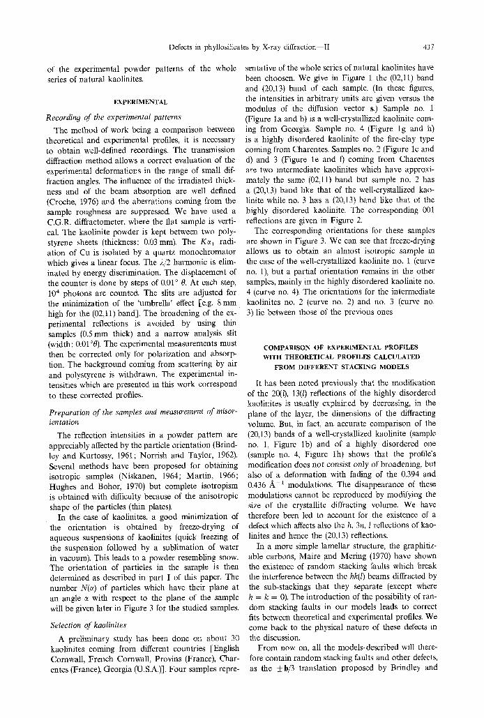
sentative of the whole series of natural kaolinites have been choosen. We give in Figure 1 the (02,11) band and (20,13) band of each sample. (In these figures, the intensities in arbitrary units are given versus the modulus of the diffusion vector s.) Sample no. 1 (Figure la and b) is a well-crystallized kaolinite com- ing from Georgia. Sample no. 4 (Figure lg and h) is a highly disordered kaolinite of the fire-clay type coming from Charentes. Samples no. 2 (Figure lc and d) and 3 (Figure le and f) coming from Charentes are two intermediate kaolinites which have approxi- mately the same (02,11) band but sample no. 2 has a (20,13) band like that of the well-crystallized kao- linite while no. 3 has a (20,13) band like that of the highly disordered kaolinite. The corresponding 001 reflections are given in Figure 2.
The corresponding orientations for these samples are shown in Figure 3. We can see that freeze-drying allows us to obtain an almost isotropic sample in the case of the well-crystallized kaolinite no. 1 (curve no. 1), but a partial orientation remains in the other samples, mainly in the highly disordered kaolinite no. 4 (curve no. 4). The orientations for the intermediate kaolinites no. 2 (curve no. 2) and no. 3 (curve no. 3) lie between those of the previous ones.
COMPARISON OF EXPERIMENTAL PROFILES
WITH THEORETICAL PROFILES CALCULATED
FROM DIFFERENT STACKING MODELS
It has been noted previously that the modification of the 20(/), 13(l) reflections of the highly disordered kaolinites is usually explained by decreasing, in the plane of the layer, the dimensions of the diffracting volume. But, in fact, an. accurate comparison of the (20,13) bands of a well-crystallized kaolinite (sample no. 1, Figure lb) and of a highly disordered one (sample no. 4, Figure lh) shows that the profile's modification does not consist only of broadening, but also of a deformation with fading of the 0.394 and 0.436 ~ - 1 modulations. The disappearance of these modulations cannot be reproduced by modifying the size of the crystallite diffracting volume. We have therefore been led to account for the existence of a defect which affects also the h, 3n, l reflections of kao- linites and hence the (20,13) reflections.
In a more simple lamellar structure, the graphitiz- able carbons, Maire and Mering (1970) have shown the existence of random stacking faults which break the interference between the hk(l) beams diffracted by the sub-stackings that they separate (except where h = k = 0). The introduction of the possibility of ran- dom stacking faults in our models leads to correct fits between theoretical and experimental profiles. We come back to the physical nature of these defects in the discussion.
From now on, all the models-described will there- fore contain random stacking faults and other defects, as the _+b/3 translation proposed by Brindley and
438 A. PLANq;ON and C. TCHOUBAR
(0) I10
002:
20
0,21
f i i 0 2 0 :.
�9 " " " ": 0 2 1
�9 "-" " \ ~ i . :" 021 �9 ~ . ~ j :-, : "..' "~ j
;: I I I 0,23 0 . 2 5 0 . 2 7
s , ~ - '
l ( b )
130 2 0 0
L 20T 13T 20
' i ~ f
I 0 . .
L" �9
d: 0 0,38
131
003 �9
0,40 0 , 4 2 0.44
s , ~-~
20
I0
I(c)
, j k I
'~#'%,a,"ss " : ,
% ,. ",,.
o - - / ~ i I 0,21 0 . 2 5 0 .25 0 . 2 7
s , ~ - '
20
0 0 .38
I ( d ) ,
�9 . ,g.
�9 . . . . . . ,
�9 k : : ' '-," ' ": i:',.: "
: -, / :
I I I 0 , 4 0 0 ,42 0 , 4 4
S , ~ - '
20
( e )
oO.27-<"
%
. . ~ .
\ % ,"
I I f 0 . 2 3 0 . 2 5 0 . 2 7
S , ~ - i
20
" I �9 : IO
I ( f )
, ; ; "
." "..-. .
\
.,,' 0 I 0 , 3 8 0 . 4 0
",%.
\
( | s
0 . 4 2 0.44
S, ~-'
2o
I
I0
I ( g )
~
, , . ,
"-....__........Y
ll(h),
20 I " �9 :
Io " " '. : " : "~ J -,...;...,, y ,
0 i I I 0 I I 0,21 0 . 2 3 0 . 2 6 0 . 2 7 0 . 3 8 0 .40 0 . 4 2 0 , 4 4
s , ~ - ~ s , ~-~
Figure 1. Experimental profiles of (02,11) and (20,13) bands for: kaolinite no. 1 (a and b), kaolinite no. 2 (e and d), kaolinite no. 3 (e and f), kaolinite no. 4 (g and h).
Defects in phyllosilicates by X-ray diffraction--II 439
20
2(0)
0 0 . 1 2
_ J , \ 0.14
s, ~-'
20
I
I0
I o
0 , t 6 OA2
2 ( b )
0.14
S, A -~
0.16
20
I
IO
0,[2
2(c)
20
i
?
�9 "-':: , ~ , o 0.14 0.16 0.12
S, ~ -t
2(d) -.
!
.
- \
, , ~ _ _ . . . ~ 0,14 0.16
S, ~ - '
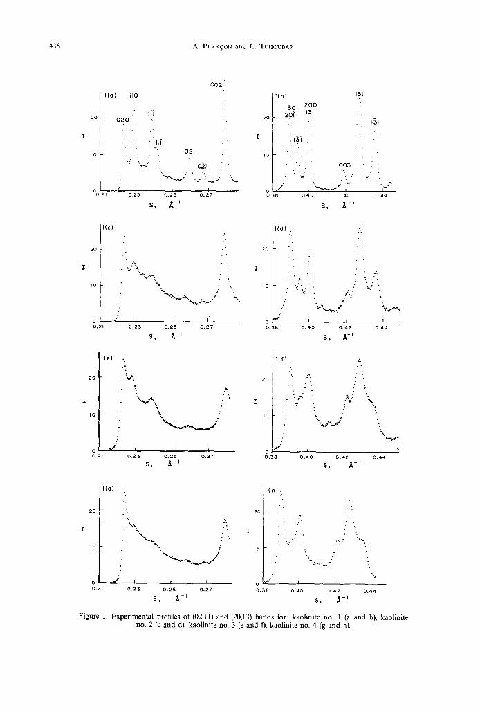
Figure 2. Experimental profiles of 001 reflections for: kaolinite no. 1 (a), kaolinite no. 2 (b), kaolinite no. 3 (c), kaolinite no. 4 (d).
A 13
Z
I,O
0 , 5
i { I i I I I ' i 7 30 60 90
O , d e g r e e s
Figure 3. Orientation curves for the four studied kaolinites samples (kaolinite no. 1: curve 1; kaolinite no. 2: curve 2; kaolinite no. 3: curve 3; kaolinite no. 4: curve 4). The horizontal dotted line corresponds to a complete
misorientation.
Robinson (1946), which will be described in the fol- lowing paragraph.
Calculated data for a model containin 9 only translative stackin 9 faults
In Part I, we have shown that the intensity dif- fracted by a powder of stackings containing only translated identical layers can be obtained from for- mula (9):
I(s) = ~ N(q))IF(Z)I 2 G(Z)T(X)dq~.
We shall detail now this calculation for the particu- lar case of kaolinites, as explained in a previous paper (Planqon and Tchoubar, 1975)�9
Calculation of M. The average number of layers per crystallite can be approximated from the 001 ex- perimental reflection by using the Scherrer formula. We obtain for the well-crystallized kaolinite (no. 1) M = 75; for the kaolinite no. 2, M = 40; for the kao- linite no. 3, M = 30; for the kaolinite no. 4, M = 25.
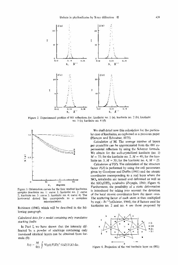
Calculation ofF(Z). The calculation of the structure factor F(Z) is performed by using the cell parameters given by Goodyear and Duffin (1961) and the atomic coordinates corresponding to a real layer where the SiO4 tetrahedra are turned and deformed as well as the A102(OH) 4 octahedra (Zvyagin, 1960; Figure 4). Furthermore, the possibility of a static deformation is introduced for taking into account the deviation of the local atomic coordinates from the mean ones. The scattering factor of each atom is then multiplied by exp(-Bs-2)(Guinier , 1964); the B factors used for kaolinites no. 2 and no. 4 are those proposed by
o' ~ . @
oO ~OH
. S i
b
Figure 4. Projection of the real kaolinite layer on (001).
440 A. PLAN~ON and C. TCHOUBAR
Gatineau and Mering (1958) for muscovite (Bsi = BA! = 0.15, B o = BOH= 0.5). These coefficients are half reduced for kaolinite no. 3 and taken equal to zero for the well-crystallized kaolinite, no. 1.
Calculation of G(Z). The calculation of the modula- tion function G(Z) involves the proportion P of ran- dom defects and the proportion r/t of _+ b/3 translative defects. We have (Mering, 1949);
sponding values of the T(X) function are given by Brindley and Mering (1951). We shall find that for the same sample, the R values are different for the (02,11) and (20,13) bands. This difference can be explained (Planqon and Tchoubar, 1975) by the exist- ence of mosaic domains.
In the previous paper, the calculation had been applied to the two extreme cases of the series of
G = 1 - U 2 2U
+ - - 1 + U 2 - 2 U c o s c o M
[-2U - (1 + U 2 ) c o s co] [1 - U M cos Mco] - (1 - U 2) U M sin Mco sin co X
(1 § U 2 - - 2U c o s o)) 2
Assuming an equal proportion of + b/3 and - b / 3 defect, we have then
U = (1 - P)[,1 - r h + rh cos(2~ s.b/3)] co = 2~ s- tk,
where t k is the translation between two well-ordered adjacent layers.
The tk translation is introduced assuming the possi- bility of a partial monoclinicity of the symmetry which increases with the disorder of the kaolinite (Brindley and Robinson, 1946, 1947; Robertson et al.,
1954). Then tk can be expressed by
tk = # 1 a + v l b + z,
with Izl = dool = 7.156 A and #1 = P~ - CM(#r - #M) and vl = vM - C~t(vr - vM), where # r and vr characterize the translation between two adjacent layers of a perfect triclinic kaolinite (#r = -0 .369 and vr = 0.024, CM = 0) while #M and vM are relative to a perfect monoclinic kaolinite (#r = -0 .333 and
VM=O, C M = 1). Calculation o f T(X). This calculation is performed
by assuming that the coherent crystallite volumes are cylinders of radius R in the layer plane. The corre-
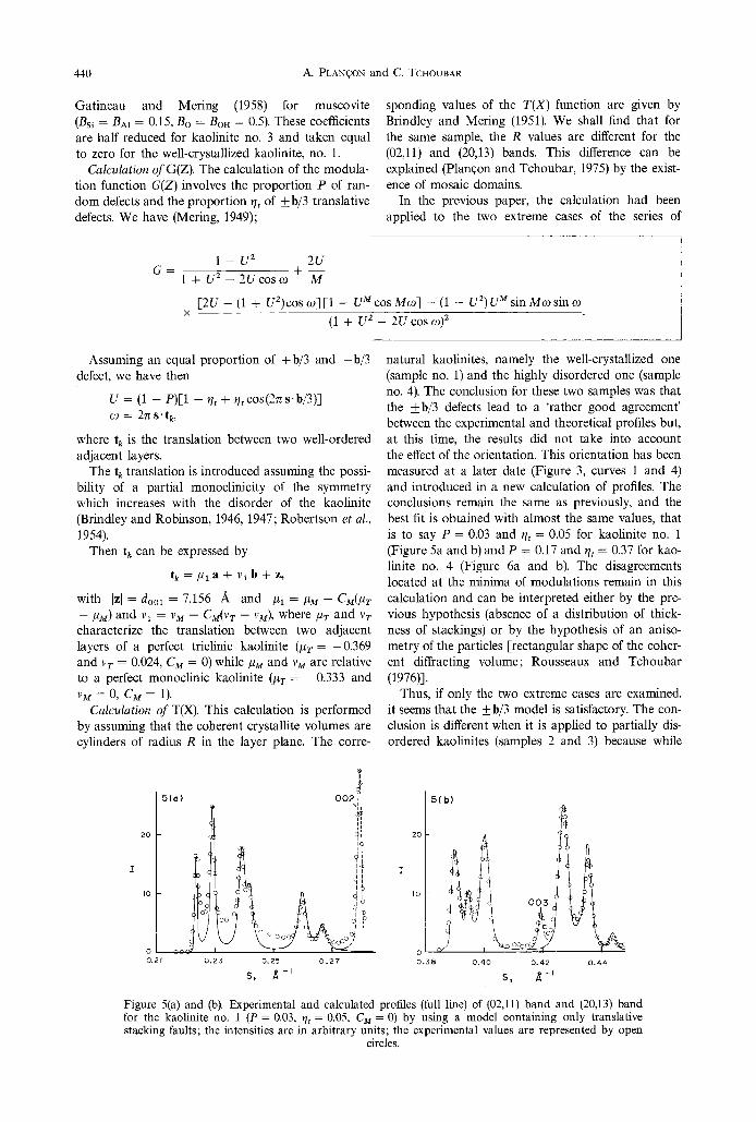
natural kaolinites, namely the well-crystallized one (sample no. 1) and the highly disordered one (sample no. 4). The conclusion for these two samples was that the _+b/3 defects lead to a 'rather good agreement' between the experimental and theoretical profiles but, at this time, the results did not take into account the effect of the orientation. This orientation has been measured at a later date (Figure 3, curves 1 and 4) and introduced in a new calculation of profiles. The conclusions remain the same as previously, and the best fit is obtained with almost the same values, that is to say P = 0.03 and t h = 0.05 for kaolinite no. 1 (Figure 5a and b) and P = 0.17 and r/r = 0.37 for kao- linite no. 4 (Figure 6a and b). The disagreements located at the minima of modulations remain in this calculation and can be interpreted either by the pre- vious hypothesis (absence of a distribution of thick- ness of stackings) or by the hypothesis of an aniso- metry of the particles [-rectangular shape of the coher- ent diffracting volume; Rousseaux and Tchoubar (1976)].
Thus, if only the two extreme cases are examined, it seems that the _+ b/3 model is satisfactory. The con- clusion is different when it is applied to partially dis- ordered kaolinites (samples 2 and 3) because while
20
I0
I I
5(0) 002~
0 , 2 5 0 .25 0 . 2 7
S, ~ -~
5(b)
o
o ,2 t o . 3 8 o , 4 o 0 . 4 2 0 , 4 4
S, ~ -~
Figure 5(a) and (b). Experimental and calculated profiles (full line) of (02,11) band and (20,13) band for the kaolinite no. 1 (P = 0.03, t h = 0.05, CM = 0) by using a model containing only translative stacking faults; the intensities are in arbitrary units; the experimental values are represented by open
circles.

Defects in phyllosilicates by X-ray diffraction--II 44l
20 20
O 0 "F
IO I0
I I I o I I I .21 0 . 2 5 0 . 2 5 0 . 2 7 0 . 3 8 0.4-0 o . 4 2 0.44-
S , ~ - I S , ~ - - I
Figure 6(a) and (b). Experimental and calculated profiles of (02,11) band and (20,13) band for kaolinite no. 4 (P = 0.17, t h = 0.37, CM = 0.25) by using a model containing only translative stacking faults.
it is possible to obtain good fits for the (20,13) bands, it is impossible to obtain a good agreement for the (02,11) bands.
We give here the example of the intermediate kao- linite no. 2. The fit is good for the (20,13) band with a proportion P = 0.07 of random defects (Figure 7b). But not any proportion t h of _+b/3 defects leads to a good agreement for the (02,11) band. With t/t = 0.34, we have the best agreement for the modula- tions located at 0.239 and 0.260 A - l , but the 0.229 A - 1 experimental modulation has almost disappeared in the calculated profile (Figure 7a). Inversely, when the first modulation is in agreement, the others are in disagreement. In the same way, it is impossible to describe the (02,11) band profile of kaolinite no. 3, by using a _+b/3 model.
So, these results show that it is impossible to de- scribe the entire series of natural kaolinites by a model containing only translative stacking faults. This model is then rejected, and we have considered models containing rotative stacking faults.
Calculated dati~ for models containing rotative stackin 9 faults
It is necessary here to give a precision concerning the 4-2z~/3 rotation and its use in the customary de- scription of kaolinite p01ytypes.
In the case of an idealized layer [SiO4 tetrahedra and A102(OH)4 octahedra not deformed and not turned], it is equivalent to say that a layer is turned by 2~/3 or that it is not rotated but takes its A1 vacan-
' ( c
20
I
Io
o o,21
b 0 0 2 ~ ' ~
Y,
i' o ~ of
o o ;
r i i
0 . 2 3 0 . 2 5 0 . 2 7
S, ~ - I
cies in another position~ This is shown in Figures 8(a) and (b). The layer of Figure 8(b) can be considered (i) as identical to the layer shown in Figure 8(a), but rotated by 2~/3 (dotted cell) or (ii) as an unrotated layer (full line cell) where the A1 vacancy is in the C position rather than the B position (Bailey, 1963).
Now, the accurate description of the kaolinite layer (Zvyagin, 1960) and of the dickite layer (Newnham, 1961) shows that, in a real layer, the tetrahedra and octahedra are turned and deformed (Figure 4). In this case, it is not equivalent to have a rotation of 2~/3 or to have only a displacement of the A1 vacancies, and one should distinguish between two kinds of de- fects, either by true rotation of non-idealized layers or by displacement of A1 vacancies in unrotated layers.
The description of the diffraction by models con- raining one or the other concept of fault uses the same mathematical formalism described in part I of this work. The intensity diffracted by a stacking con- raining stacking faults and/or variations in the layer structure can be obtained from formula (10), modified by taking into account the partial orientation
m g
j = l
x [F*k(Z)]j~u(Z) Tu(X) dq~.
Rotation of invariable layers. In such a model, one can consider
20
0 0,38
7(
_ 003
d o/ ~,_2/ \ o o o/Z...
I 0 . 4 0 0 . 4 2
S, ~-~
I
0 , 4 4
Figure 7(a) and (b). Experimental and calculated profiles of (02,11) band and (20,13) band for kaolinite no. 2 (P = 0.07, t h = 0.34, CM = 0) by using a model containing only translative stacking faults.
C,C.M, 25/6--E

442 A. PLANgON and C. TCHOUBAR
/ �9 8 (b} ~ � 9
@ - 0 - ~ .-@/
'~..~-I I \ ~ ~ �9 \"-. �9 i C'I .'
~ ,- oR + P
~ � 9 / ~ B ~ C , ' ~ � 9 , t ~'--< ,--~,' t "~ ~ . ~.. ' ",1 ~ %-.
R �9 r ' , �9 ~-,..f" m , , ~ '~ e }:o' , .o~ o , ?
-- ,~- ,5, z. ).v--t.)-~
b b J
Figure 8(a) and (b). Rotated idealized layers for kaolinite.
(i) arbitrary +2~/3 or - 2 ~ / 3 rotations (Murray, 1954),
(ii) rotative stacking faults such two adjacent layers are disposed one relative to the other only as in the dickite (Zvyagin, 1967),
(iii) rotative stacking faults which lead to the enan- tiomorphic polytype (Zvyagin, 1967).
In a previous paper (Planqon and Tchoubar, 1976), it has been shown that cases (ii) and (iii) should be rejected, because they never lead to an almost unmo- dulated (02,11) band.
What we can add now is that model (i) also should be rejected. In fact, this model leads to a correct fit for the (02,11) band but, since the symmetry of the
9(c
20
I IO
_21
o 0 2
$ d
o i
o ~ } ./
I I I ? . 2 3 0 . 2 5 0 . 2 7
s, ~ - f
layer is not exactly trigonal, a % proportion of 2~/3 rotation modifies too much the (20,13) band profile by comparison with the experimental profile.
This can be illustrated by the case of kaolinite no. 2. The proportion P of random defects is determined by using the (20,13) band (P = 0.07) and is besides introduced in the calculation of the (02,11) band simultaneously with an t/, proportion of defects by ___ 2~/3 rotation. The best fit is obtained for t/, = 0.47 (Figure 9a). But even without using the 0.07 propor- tion of random defects, the recalculated profile of the (20,13) band with t/, = 0.47 is much more deformed (Figure 9b) than the experimental profile (Figure 9c): one notices that the 0.394 ,~-~ reflection disappears
9(b:
20
io
%.3d j J
0 , 4 0 0 . 4 2
s, ~- t
\ 0 , 4 4
9(c) ,
20
I
,o . "~:" ! .
.
o
0.58
J,
�9 ; : " : ~ �9
.;;..
I I I
0 . 4 0 0 . 4 2 0 . 4 4
S, A -~ Figure 9(a}ffc). Experimental and calculated profiles of (02,11) band and (20,13) band of kaolinite no. 2 by using a model containing 2~/3 rotations of real layers�9 (a) (02,11) band profile calculated with P = 0.07 and t/, = 0.47, (b) (20,13) band profile calculated with t/, = 0.47, (c) experimental (20,13)
band profile.
Defects in phyllosilicates by X-ray diffraction II 443
O(a}
20
I0
o / 0.21
I I I 0 , 2 3 0 . 2 5 0 , 2 7
S, ~-t
O ( b
2o
I
IO
O.21 I I i
0 . 2 3 0 , 2 5 0 . 2 7
�9 s, ~,-~
~0(
20 1-
Io
o o.21
I I I 0 , 2 3 0 . 2 5 0 . 2 7
S ~-~
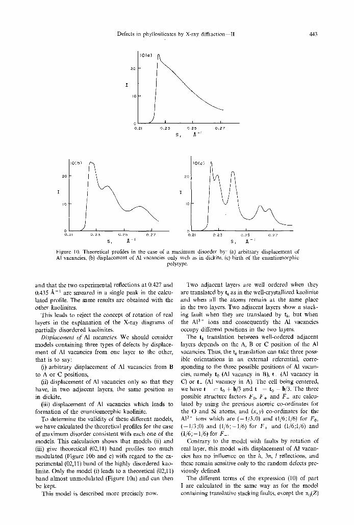
Figure 10. Theoretical profiles in the case of a maximum disorder by: (a) arbitrary displacement of A1 vacancies, (b) displacement of A1 vacancies only such as in dickite, (c) birth of the enantiomorphic
polytype.
and that the two experimental reflections at 0.427 and 0.435 A-1 are smeared in a single peak in the calcu- lated profile. The same results are obtained with the other kaolinites.
This leads to reject the concept of rotation of real layers in the explanation of the X-ray diagrams of partially disordered kaolinites.
Displacement of A1 vacancies. We should consider models containing three types of defects by displace- ment of A1 vacancies from one layer to the other, that is to say:
(i) arbitrary displacement of A1 vacancies from B to A or C positions,
(ii) displacement of A1 vacancies only so that they have, in two adjacent layers, the same position as in dickite,
(iii) displacement of A1 vacancies which leads to formation of the enantiomorphic kaolinite.
To determine the validity of these different models, we have calculated the theoretical profiles for the case of maximum disorder consistent with each one of the models. This calculation shows that models (ii) and (iii) give theoretical (02,11) band profiles too much modulated (Figure 10b and c) with regard to the ex- perimental (02,11) band of the highly disordered kao- linite. Only the model (i) leads to a theoretical (02,11) band almost unmodulated (Figure 10a) and can then be kept.
This model is described more precisely now.
Two adjacent layers are well ordered when they are translated by t k as in the well-crystallized kaolinite and when all the atoms remain at the same place in the two layers. Two adjacent layers show a stack- ing fault when they are translated by tk, but when the A13§ ions and consequently the A1 vacancies occupy different positions in the two layers.
The tk translation between well-ordered adjacent layers depends on the A, B or C position of the A1 vacancies. Thus, the t k translation can take three poss- ible orientations in an external referential, corre- sponding to the three possible positions of A1 vacan- cies, namely to (A1 vacancy in B), t§ (A1 vacancy in C) or t_ (A1 vacancy in A). The cell being centered, we have t+ = to + b/3 and t_ = to - b/3. The three possible structure factors F0, F§ and F_ are calcu- lated by using the previous atomic co-ordinates for the O and Si atoms, and (x, y) co-ordinates for the A13+ ions which are ( -1 /3;0) and (1/6;1/6) for F0, ( -1/3;0) and (1/6;-1/6) for F+ and (1/6;1/6) and (1/6;-1/6) for F_.
Contrary to the model with faults by rotation of real layer, this model with displacement of A1 vacan- cies has no influence on the h, 3n, 1 reflections, and these remain sensitive only to the random defects pre- viously defined.
The different terms of the expression (10) of part I are calculated in the same way as for the model containing translative stacking faults, except the ~u(Z)

444 A. PLAN~ON and C. TCHOUBAR
terms which are calculated by using the Q matrix below:
Q =
t l a H a ( i - t/e)exp(2nis- to) 2" exp(2nis- to) '~ exp(2nis.2 to)
2exp(22zis.t+) (1 - ~/e)exp(2~zis.t+) q-~ exp(2zcis-t+) 2
~ exp(2rtis, t_ ) r/~ exp(2nis- t_ ) (1 - r/d)exp(2rtis �9 t_ ) 2
where r/d is the proportion of defects by displacement of A1 vacancies.
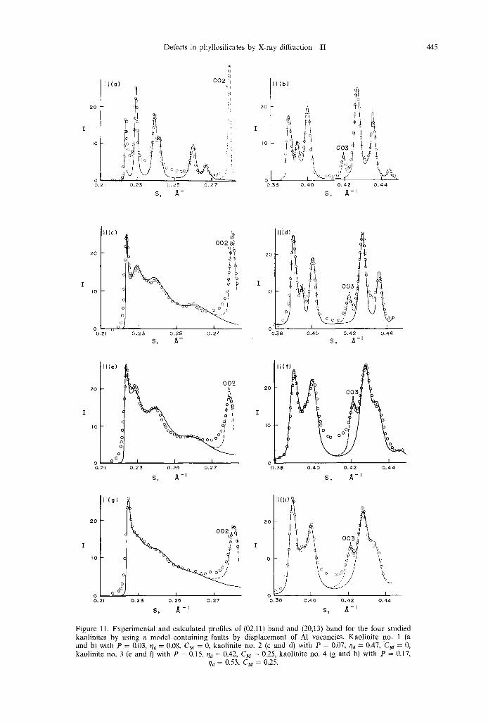
The best fits obtained with this model are shown in the Figure 11 [one does notice that the (20,13) band profiles take account for the foot of the (02,11) band] :
For the well-crystallized kaolinite no. 1 (Figure 1 la and b) with a proportion P of random defects equal to 0.03 and a proportion r/d of faults by displacement of AI vacancies from one layer to the adjacent one equal to 0.08. The (02,11) band is calculated with a radius crystallite R1 = 750 A while the (20,13) band is calculated with R 2 = 250 A.;
for the first intermediate kaolinite no. 2 (Figure l lc and d) with P = 0.07 and qn = 0.47 (RI = 1000 A, R 2 = 250 A);
for the second intermediate kaolinite no. 3 (Figure l l e and f) with P = 0.15 and t/d = 0.42 (R1 = 500A, R2 = 125 A);
for the highly disordered kaolinite no. 4 (Figure l l g and h) with P = 0.17 and r/e = 0.53 (R~ = 600 A, R2 = 150 s
We can then notice a rather good agreement between the experimental and calculated profiles while the differences which persist at the minima of modulations can probably be interpreted, as pre- viously, by an absence of distribution of thickness in the calculations or by an anisometry of the diffracting volume. The accuracies of the P and t/a proportions are about 20% for the well-crystallized kaolinite and 6% for the disordered ones.
So the experimental profiles of the studied kao- linites, representative of the whole series of natural kaolinites more or less disordered, can fairly be repro- duced by using a stacking model containing simul- taneously faults by displacement of A1 vacancies from one layer to the other, and random stacking faults.
D I S C U S S I O N
Hypothesis oJ interaction only between first neighbour- ing layers
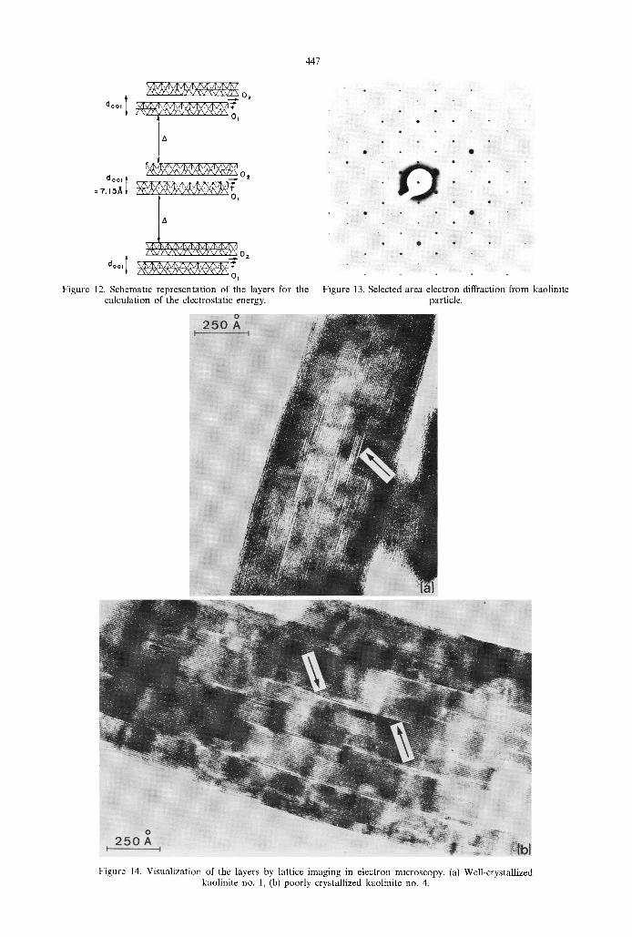
The calculations which have been done assume an interaction between first neighbouring layers only. The validity of this hypothesis in the case of kaolinite is first checked by the quality itself of the fit between the calculated intensities and the experimental ones, Moreover, calculations of interaction between layers have been performed by Giese (personal communica- tion, 1976), who calculated the electrostatic energy for
structural models compounds with packets of two layers. Inside a packet, the layers are 7.15 A apart while the packets are a distance A apart (Figure 12). The electrostatic energy of the structure is calculated for different t~ shifts of layers inside a packet and for different values of A. The value of A being fixed, the calculated energies for each ts shift are written on an energy map where the lower parts correspond to the stable mutual positions of the layers inside a packet (Giese, 1973, 1974). Giese sees that for A greater than 7 ~ the energy maps are closely similar, that is to say that the electrostatic interaction between packets becomes negligible. It can be concluded that interaction between kaolinite layers is sensitive only to a distance of a few ~mgstrSms and that kaolinite layers interact only with their first neighbours.
Physical sense of random defects
The random defects described above suppress the interference between the beams diffracted by the sub- stackings that they separate. They can be conceived in two different ways, either the sub-stacking are ran- domly rotated around the normal to the layer or they are randomly shifted parallel to the layer plane (Maire and Meting, 1970). The selected area electron diffraction shows that a morphologicaly single par- ticle of kaolinite always gives a monocrystal diffrac-
t ion pattern (Figure 13). This leads to the conclusion that the random defects are defects by random trans- lation.
Moreover, the doo~ distance between layers obtained from the position of the band modulations is always of 7.15 A, while the do01 distance obtained from the position of the 001 reflections reaches 7.20 ]t and even more in highly disordered kaolinites. This shows that the 001 reflections and the (hk) bands are not produced by the same coherent volumes (Maire and Mering, 1970). The coherent volume for the (hk) band are the sub-stackings limited by a random defect on each side; inside the sub-stacking, the layers are equidistant as in the perfect triclinic kaolinite. On the contrary, the coherent volume producing the 001 re- flections includes the random defects; then a measure- ment, from the reflections, of a value of doo ~ greater than 7.15 A,, shows that the increasing of the basal distance is located only between two adjacent layers randomly translated.
The lattice imaging in electron microscopy allows a visualisation of these defects. Figure 14 corresponds to a high resolution image obtained from a cross-sec-
Defects in phyllosilicates by X-ray di f f rac t ion-- I I 445
20
I0
0,21
ll(a)
0 . 2 3
002
N
0 . 2 5 0 . 2 7
S, ~-~
i l l (b)
20 -
dO3 I
0 . 3 8 0 , 4 0 0 . 4 2 0 , 4 4
II(c)
2 0 -
I 0 -
00.21
69
r I I
0 . 2 5 0 . 2 5 0 , 2 7
S, ~-I
003 ,!
I
0 , 4 2
S, ~-J
I
o , 4 4
lice) L o o z
20 -
o\ ~ ~ ok. d I
o %o o :/ ' , o
g
9 I I I .21 0 . 2 3 0 . 2 ~ 0 , 2 7
S, ~ - i
20
I
Io
~ 3
I ( f )
i 0
oo S / Y
I 1 I 0 , 4 0 0 , 4 2 0 . 4 4
S, ~ - t
II(g)
2 0 "
tO "
o 0 0.21
I t I
0 , 2 3 0 . 2 5 0 , 2 7
s, ~ -t
2O
I
I 0
/ 0 0 . 3 8
o
o
0 . 4 0 0 , 4 2 0 . 4 4
s, ~-i
Figure 11. Experimental and calculated profiles of (02,11) band and (20,13) band for the four studied kaolinites by using a model containing faults by displacement of A1 vacancies. Kaolinite no. 1 (a and b) with P = 0.03, tld = 0.08, CM = 0, kaolinite no. 2 (c and d) with P = 0.07, tld = 0.47, Cz~ = 0, kaolinite no. 3 (e and t) with P = 0.15, tld = 0.42, CM = 0.25, kaolinite no. 4 (g and h) with P = 0.17,
qd = 0.53, C M : 0.25.
446 A. PLANqON and C. TCHOUBAR
15
1 6 ( o ) / \ / \
1 6 ( b )
/ i F . . . .
/ \ 16(c) / ' - ~ - - - ~ ' / / \ ~ \\\ ------ II ~ \\ ----
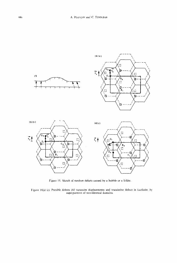
Figure 15. Sketch of random defects caused by a bubble or a folder.
Figure 16(a)-(c). Possible defects (AI vacancies displacements and translative defect) in kaolinite, by superposition of non-identical domains.
447
/ x ~ / ' / \ / ~ \ / ) ' x / x v x v \ v y \ 02
doo, ] ~/~j~^/~j~^/l~/l~^/~'~ / \\/Y\/X~YVXVY'X/Y~./T~ 0 l
d o ~ ~, /1X ,/1~ /Ix "~
Figure 12, Schematic representation of the layers for the calculation of the electrostatic energy.
Figure 13. Selected area electron diffraction from kaolinite particle.
Figure 14. Visualization of the layers by lattice imaging in electron microscopy. (a) Well-crystallized kaolinite no. 1, (b) poorly crystallized kaolinite no. 4.

Defects in phyllosilicates by X-ray diffraction--II 449
tion of particles of kaolinite perpendicular to the layer planes (Tchoubar and Clinard, to be published). Figure 14(a) shows a domain of a particle of well-crys- tallized kaolinite where there exists a great number of bubbles. Figure 14(b) shows a particle of poorly crystallized kaolinite no. 4. Within a particle, the layers are generally parallel and distant from about 7.15 /~ but, in some regions (shown by arrows), two adjacent layers are distant from 8 or 9 ~. Such defects can originate the random translation described above because the 'bubble' or 'folder' leads simultaneously to a modification of the basal spacings and to a ran- dom translation of the cells of adjacent layers (Figure 15). This translation probably remains random beyond the bubble domain.
Physical sense of defects by displacement of A1 vacan- cies
This type of defect is in agreement with the conclu- sions drawn by Mansfield and Bailey (1972) in a study of twins in kaolinite. These authors propose a growth of kaolinite based on three types of domains in which the A1 vacancies stay in the A, B or C position. At the end of the growth, a layer should be built of differ- ent domains Separated by twin's joints. Such a de- scription allows us to give a physical sense to the defects by displacement of A1 vacancies: it corre- sponds to the superimposition of layers where the A1 vacancies do not stay in the same position.
Furthermore, the Mansfield and Bailey description involves a possible coexistence of displacement of A1 vacancy defect with _+b/3 translative defect. For example (Figure 16a), let us take two layers translated by a to vector which is tk for the two regions where B domains (noted B 1 and B2) are superimposed. Then the superimposition of a C2 domain over a B1 domain (Figure 16b) constitutes a defect by displace- ment of A1 vacancies while, for example, a superimpo- sition of a B2 domain over a C1 domain leads to a defect with simultaneously a displacement of A1 vacancies and a b/3 translation (Figure 16c).
One can see that, from twins, it becomes logical to describe the partially disordered kaolinites by a
model which contains, in addition to the random shifts, simultaneously displacement of A1 vacancy de- fects and b/3 translative defects. The case of such a model improves the fit. We give, in Figure 17, the example of kaolinites no. 2 and 3. Figure 17(a) corre- sponds to the (02,11) profile of the kaolinite no. 2 with the P proportion of random defects previously determined (P ~ 0.07), a ~/n proportion of defects by displacement of A1 vacancies of 0..42 and a t/, propor- tion of +h/3 translations of 0.06. We obtain a very good agreement between the experimental and theor- etical profile, better than the fit obtained in taking into account only defects by displacement of A1 vacancies. The same conclusion remains for the kao- linite no. 3 (Figure 17b) with P = 0.15, ~/e = 0.30 and t/r = 0.12.
CONCLUSION
Until now, the different attempts to describe the defects of kaolinites were based on the ideas that (i) the hkl reflections with k = 3n are Bragg reflections not modified by any stacking fault, while (ii) the hkl reflections with k = 3n are affected by +b/3 trans- lations or +2~/3 rotations. Practically, the authors who have studied the stackings have used only the concept of +b/3 translations.
With regard to this conception, our work provides several important precisions.
(1) The h, 3n, I reflections are not broadened Bragg reflections but true continuous diffraction bands, more or less modulated. They can be explained by the existence, in the stackings, of random shifts of the layers parallel to the layer plane, associated with a modification of the basal spacings (existence of bub- bles or folders).
(2) The disordered kaolinites are customary classi- fied as b-axis disordered minerals. On the contrary, our work leads us to consider that the defect which plays the main role is the displacement, from one layer to the other (or from one domain to another in the same layer), of the A1 vacancies. In this concept, the b/3 translations are only secondary effects (in a
2 0
I0
7~bl 17(al ~
- ~ ,
:!
r - .n c~ o ]
0 , 2 3 0 , 2 5 0 . 2 7
S, 4 - '
2 0
l 0
<
nq
002 ~l
i I L 0 . 2 3 0 . 2 5 0 . 2 ?
S, ~,-' Figure 17. Final fit for experimental and calculated profiles of (02,11) band of kaolinite no. 2 and kaolinite no. 3 by using a model containing faults by displacement of A1 vacancies and by _+b/3 translation. (a) Kaolinite no. 2 (P = 0.07, qa = 0.42, ~/, = 0.06, CM = 0), (b) kaolinite no. 3 (P = 0.15,
~/a = 0.30, t h = 0.12, CM = 0.25).
450 A. PLAN~ON and C. TCnOUBAR
small proportion) of the A1 vacancies displacements. One should notice that such a model of faults by displacement of A1 vacancies allows us to find, in the stacking, layers with the succession BC or CB, that is to say the 'birth of the dickite polytype'.
(3) It is necessary to reject the stacking model con- taining true rotations of real layers, because this de- fect does not allow us to interpret all the different parts of the experimental diagrams. Now, the kao- linite polytypes are frequently described by the notion of rotation of layer. In the case of an idealization of the layer structure (without any deformation of tetrahedral and octahedral sheets), the notion of rotation of layers is identical to the notion of dis- placement of A1 vacancies, But, because an accurate description of polytypes requires the use of real layers, it is necessary to substitute the concept of displace- ment of A1 vacancies to the notion of rotation of layers.
Then this concept of defects in kaolinites is in agreement with the existence of polytypes of kaolinite, and with the presence of twins in this mineral. It allows also to interpret some physico-chemical fea- tures of these minerals such as the infrared spectra in the domain of the O H group vibration bands (Bar- rios etal., 1977).
REFERENCES
Bailey, S. W. (1963) Polymorphism of the kaolin minerals: Am. Miner. 48, 1196-1209.
Barrios, J., Planqon, A., Cruz, M. 1. and Tchoubar, C. (1977) Qualitative and quantitative study of stacking faults in an hydrazin e treated kaolinite--relationshi p with the infrared spectra: Clays and Clay Minerals 25, 42~429.
Brindley, G. W. (1961) The X-Ray Identification and Crys- tal Structures of Clay Minerals (Edited by Brown, G.), pp. 51-131: The Mineralogical Society, London.
Brindley, G. W. and Kurtossy, S. (1961) Quantitative deter- mination of kaolinite by X-ray diffraction: Am. Miner. 46, 1205-1215.
Brindley, G. W. and Meting, J. (1951) Diffraction des rayons X par los structures en couches d6sordonn6es: Acta Cryst. 4, 441-447.
Brindley, G. W. and Robinson, K. (1946) Randomness in the structures of kaolinitic clay mir~erals: Trans. Faraday Soc. 42B, 198-205.
Brindley, G. W. and Robinson, K. (1947) X-ray study of some kaolinitic fire clays: Trans. Brit. Ceram. Soc. 46, 49-62.
Croche, R. (1976) Etudes exp6rimentales et th6oriques des corrections d'aberrations instrumentales d'un dia- gramme de diffraction des rayons X: Th6se, Paris.
De CourviUe, J., Tchoubar, C. and Tchoubar, D. (to be published) 3. Appl. Cryst.
Fleurenee, A. and Nicolas, J. (1964) Observations sur la notion d'ordre et de d6sordre de certains min6raux de groupe de la kaolinite: Bull. Gr. Ft. Ar 9. 14, 149-162.
Gatineau, L. and Meting, J. (1958). Pr6cisions sur la struc- ture de la muscovite: Clay Miner. Bull. 3, 238-243.
Giese, R. F. (1973) Interlayer bonding in kaolinite, dickite and nacrite: Clays and Clay Minerals 21, 145-149.
Giese, R. F. (1974) The interlayer bonding in one-layer kaolin structures: Clays and Clay Minerals 22, 139-140.
Goodyear, B. and Duffin, M. A. (1961) An X-ray examin- ation of an exceptionally well crystallized kaolinite: Miner. Mag. 32, 902-907.
Guinier, A. (1964) Thdorie et Technique de la Radiocristallo- 9raphie: Dunod, Paris.
Hugues, R. and Bohor, B. (1970) Random clay powders prepared by spray-drying: Am. Miner. $fi, 1780-1786.
Maire, J. and Meting, J. (1970) Chemistry and Physics of Carbon (Edi!ed by Walker, P. L.), Vol. 6, pp. 125-189: Marcel Dekker, New York.
Mansfield, C. F. and Bailey, S. W. (1972) Twin and pseudo- twin intergrowth in kaolinites: Am. Miner. 57, 411-425.
Martin, R. T. (1966) Quantitative fabric of wet kaolinite: Clays and Clay Minerals 14, 271-287.
Meting, J. (1949) L'interf6rence des rayons X dans los syst6mes • stratification ddsordonn6e: Acta Cryst. 2, 371-377.
Mitra, G. B. (1963) Structure defects in kaolinite: Z. Kris- tallogr. 119, 161-175.
MRra, G. B. and Bhattacherjee, S. (1969a) Layer disorder in kaolinite during dehydration: Acta Cryst. B25, 1668-1669.
Mitra, G. B. and Bhattacherjee, S. (1969b) X-ray diffraction studies on the transformation of kaolinite into metakao- lin--I. Variability of interlayer spacings: Am. Miner. 54, 1409-1418.
Mitra, G. B. and Bhattacherjee, S. (1970) X-ray diffraction studies on the transformation of kaolinite into metakao- lin--II. Study of layer shift: Acta Cryst. B26, 2124-2128.
Murray, H. H. (1954) Structural variations of some kao- linites in relation to dehydrated halloysite: Am. Miner. 39, 97-108.
Murray, H. H. and LYONS , S. C. (t956) Correlation of paper-coating quality with degree of crystal perfection of kaolinite: Clays and Clay Minerals 4, 3140.
Newnham, R. E. (1961) A refinement of the diekite struc- ture and some remarks on polymorphism in kaolin minerals: Miner. Ma 9. 32, 683-704.
Niskanen, E. (1964) Reduction of orientation effects in the quantitative X-ray diffraction analysis of kaolin minerals: Am. Miner. 49, 705-714.
NoNe, F. R. (1971)A study of disorder in kaolinite: Clay Miner. 9, 71-80.
Nortish, K. and Taylor, R. M. (1962) Quantitative analysis by X-ray diffraction: Clay Miner. Bull. 5, 98-109.
Plan~on, A. and Tchoubar, ~ C. (1975) Etude des fautes d'empilement dans les kaolinites partiellement d6sordon- n6es--I. Mod61e ne comportant que des fautes par trans- lation: J. Appl. Cryst. 8, 582-588.
Plan~on, A. and Tchoubar, C. (1976) Etude des fautes d'empilement dans les kaolinites partiellement d6sordon- n6es--lI. Modble d'empilement comportant des fautes par rotation: J. Appl. Cryst. 9, 279-285.
Planqon, A. and Tchoubar, C. (1977) Determination of structural defects in phyllosNcates by X-ray diffrac- tion--I. Principle of calculation of the diffraction phenomenon: Clays and Clay Minerals 25, 430-435.
Robertson, R. H. S., Brindley, G. W. and Mackenzie, R. C. (1954) Mineralogy of kaolin clays from Pugu, Tan- ganyika: Am. Miner. 39, 118-138.
Rousseaux, F. and Tchoubar, D. (1975) M6thode d'analyse du profil de bande produite par des feuillets diffractants ayant une forme anisom6trique: J. Appl. Cryst. 8, 365-371.
Tchoubar, C. and Clinard, C. (to be published). Zvyagin, B. B. (1960) Electron diffraction determination
of the structure of kaolinite: Dokl. Akad. Nauk S.S.S.R. 130(5).
Zvyagin, B. B. (1967) Electron Diffraction Analysis of Clay Mineral Structures: Plenum Press, New York.