Determination of High Performance Concrete (HPC ...
55
m Research, Development and Technolo3y D ~ v ~ s ~ o n RDT 99-008 Determination of High Performance Concrete (HPC) Characteristics
Transcript of Determination of High Performance Concrete (HPC ...
m Research Development and Technolo3y D ~ v ~ s ~ o n
RDT 99-008
Determination of High Performance
Concrete (HPC) Characteristics
TECHNICAL REPORT DOCUMENTATION PAGE
I Report No 2 Government Accession No 3 Recipients Catalog No
~RDT99-008
4 Title and Subtitle 15 Report Date
Determination of High Performance Concrete (HPC) Characteristics
6 Performing Organization Code MoDOT
7 Authods) 8 Performing Organization Report No
Missouri Department of Transportation RDT 99-008 1 RI97-046
9 Performing Organization Name and Address 10 Work Unit No
Missouri Department of Transportation
Research Development and Technology Division I I Contract or Grant No
PO Box 270 - Jefferson City MO 65102
12 Sponsoring Agency Name and Address 13 Type of Report and Period Covered
Missouri Department of Transportation
Research Development and Technology Division 14 Sponsoring Agency Code
PO Box 270 - Jefferson Citv MO 65 LO2
IS Supplementary Notes
This investigation was conducted in cooperation with the US Depamnent of Transportation Federal Highway Administration
16 Abstract
Two companion bridges were built on Missouri Route 21 over Route M in Jefferson County The prestressed girders in the northbound bridge were fabricated with high performance concrete PC) with a design strength of 10000 psi The prestressed
girders in the southbound bridge were fabricated with conventional concrete with a design strength of 5000 psi Various
characteristics of the HPC and conventional concrete were determined and compared These characterictics include compressive
strength chloride permeability freeze-thaw durability and an analysis of the air void systems Both the HPC and the conventional
concrete exceeded the design strength Chloride permeability was very low for the HPC and low to moderate for the conventional
concrete The HPC exhibited poor frcezethaw resistance while the conventional concrete showed moderate to excellent
freeze-thaw resistance Both the HPC and the conventional concrete had air void parameters outside of recommended ranges
In addition to determining the above chwteristics of each of the concrete mixes a curing system similar to the match-cure systen
was evaluated The test results of specimens cured with the curing system arc believed to be more representative of the concrete in
the girdes than member-cured specimens
Curing temperatures were collected at many locations in the girders The tempCraNre data suggests some modifications to the
steam curing process may be warranted to ensure a consistent curing condition for the entire girder
This study has shown that HPC can be produced with locally available materials in Missouri and could possibly lead to improved
bridge performance in the future
17 Key Words 18 Distribution Statement
]high performance concrete silica fume high range water reducer No nstrictions This document is available to the public
freeze-thaw durability chloride permeability curing tempeiNre through National Technical Information Center Springfield
match-cure prestress 1 Virginia 22161
19 Security Classification (of this report) 120 Security Classification (of this page) 121 No of Pages 122 Price
Unclassified Uncla~sified 22 wlo Appendices
Form DOT F 17W7 (0698)
I
RESEARCH INVESTIGATION RI97-046
DETERMMATION OF HIGH PERFORMANCE CONCRETE (HPC) CHARACTERISTICS
PREPAREDBY MISSOURI DEPARTMENT OF TRANSPORTATION
RESEARCH DEVELOPMENT AND TECHNOLOGY DIVISION
Written by TIM CHOJNACKI PE
Acknowledgment to Eric Wade Egyptian Concrete Company
Patty Brake-Lemongelli Research Director Dave Amos Research and Development Assistant
Jeff Joens Senior Research and Development Technician
JEFFERSON CITY MISSOURI Submitted
September 1999
The opinions findings and conclusions expressed in this publication are those of the principal investigator and the Research Development and Technology Division of the Missouri Department of Transportation
They arc not necessarily those of the U S Department of Transportation Federal Highway Administration This nport does not constitute a standard specification or regulation
EXECUTIVE SUMMARY
The objective of this study was to determine the characteristics of high-performance concrete (HPC) used in prestressed 1-girders and compare them with the characteristics of conventional concrete commonly used in prestressed I-girders Two companion bridges were constructed The northbound Missouri Route 21 bridee over Route M in Jefferson County was designed and built using HPC prestressed 1-girders with design strength of 10000 psi The southbound structure was designed and built using conventional
concrete 1-girders with design strength of 5000 psi The bridges are subjected to similar environmental and traffic impacts which will allow for a valuable comparison throughout their service life
Three concrete mixes were used in the ~roiect Each of these three mixes included a superplasticizer One HPC mix was used for all of the girders in the northbound bridge Girders for the southbound bridge were fabricated from two conventional mixes referred to in this report as COW I a n d c 0 W II The C O W 1 and CONV 11mixes were basically the same with the exception of the coarse aggregate used
The HPC mix had a water to cementitious materials (wlc) ratio of 0243 which included 55 silica fume by weight of cement The coarse aggregate was Plattin Limestone The 28 day strength was 12360 psi The HPC had a very low permeability but displayed poor freeze-thaw durability It is felt the poor freeze-thaw durability may be attributed to the coarse aggregate used Further study is warranted to determine the reason for the poor results
The CONV I mix had a wlc of 0305 The coarse aggregate was Plattin Limestone The 28 day strength was 9270 psi COW I had low permeability but displayed marginal freeze-thaw resistance The same coarse aggregate was used in this mix as in the HPC mix
The C O W IImix had a wc of 0328 The coarse aggregate was Derby Doe Run Dolomite The 28 day strength was 6850 psi COW I1 has moderate permeability and excellent freeze-thaw resistance The coarse aggregate used in this mix is different than that used in the HPC and COW I
In addition to determining the characteristics of the HPC and conventional mixes a -MoDOT fabricated curing system was evaluated The curing system designed to provide a match-cure consisted of a converted refrigerator and a series of thermocouples The temperature of the girder was monitored so that the temperature of specimens the curing box could be maintained at that of the gmIer For the HPC the temperature of specimens was maintained within approximately 3OF of the girder This match-cure resulted in compressive strength of the HPC 85 higher than that of a member-cured specimen at three days At 28 days the match-cured compressive strength was 107 higher than the member-cured However at 56 days the member-cured compressive strength was slightly higher (13) than the match-cured compressive strength
The study has demonstrated that HPC can be used in the fabrication of prestressed I-girders Design strengths of i 0000 psi can be used to increase spans increase beam spacing and utilize shallower girders Increased resistance to chloride penetration (reduced permeability) is expected to lead to longer service life and reduced maintenance of the bridge Good freeze-thaw resistance while not observed in all of the mixes in this study should also lead to reduced maintenance and longer service life The varied freeze- thaw performance seen in this study will be investigated further in an attempt to explain the poor performance
The two bridges will be monitored throughout their service life and periodic reports will be created documenting their performance
TABLE OF CONTENTS
List of Figures
List of Tables
Introduction
Objectives
Discussion of Present Conditions
Project Costs and Benefits
Technical Approach
Results and Discussion
Compressive Strength
Modulus of Elasticity
Chloride Permeability
Freeze-Thaw Durability
Air Void System Analysis
Curing Temperatures
Conclusions
Recommendations
Implementation
Bibliography
TABLE OF CONTENTS (Contd)
Appendix A - High Performance Concrete Special Provision
Appendix B - Work Plan
Appendix C - Location of Thermocouples in I-Girder
Appendix D - Comparison of Girder Curing Temperatures and Cylinder Curing Temperatures
Appendix E - Comparison of Girder Mid-span Curing Temperatures
Appendix F - Comparison of Girder Curing Temperatures Near and Away from Steam Source
LIST OF FIGURES
Figure 1 Comparison of MoDOT Type 6 and MoDOT Type 4 I-Girders
Figure 2 5
8
9
Comparison of Preliminary (Conventional) and HFC Bridge Design
Figure 3 Compressive Strength (Comparison of HFC CONV I and CONV 11)
Figure 4 HPC Compressive Strength (Comparison of Member-Cured and Match-Cured)
iii
LIST OF TABLES
Table 1 Comparison of HPC and Conventional Girder Costs
Table 2 Mix Proportions
Table 3 Compressive Strength
Table 4 Ability to Resist Chloride
Table 5 Coarse Aggregate Properties
Table 6 Freeze-Thaw Durability
Table 7 Summary of Air Void Analysis
INTRODUCTION
As a member of the American Association of State Highway and Transportation Officials (AASHTO) High-Performance Concrete (HPC) Lead State Team Missouri is committed to promoting the implementation of HPC technology in highways and highway structures
Early attempts to improve concrete focused on increased compressive strength The term high-strength concrete was frequently used However increased strength alone does not necessarily improve the concretes performance or durability Enhanced performance of concrete is a critical consideration when evaluating future maintenance costs or life- cycle costs of a highway or bridge
The term high-performance concrete (HFC) is now often used The American Concrete Institute (ACI) has recently defined HPC as
concrete meeting special combinations of performance and uniformity requirements that cannot always be achieved routinely using conventional constituents and normal mixing placing and curing practices
High-performance concrete is concrete in which certain characteristics are developed for a particular application and environment Examples of characteristics that may be considered critical for an application are
ease of placement density compaction without segregation heat of hydration early age strength toughness long term mechanical properties volume stability permeability long life in severe environments
Advantages of using HPC in bridge design include
longer spans increased durability increased beam spacing improved mechanical properties shallower members
Longer spans increased beam spacing and shallower members all result in less required material Less material depending on the cost of the constituents could result in a lower initial cost of the bridge The increased durability of the bridge members results in longer life fewer repairs and lower overall maintenance costs This potential savings in both initial and maintenance costs make HPC very amactive to owners throughout the concrete industry
This report details Missouris first HPC bridge project The HPC was used to fabricate prestressed I-girders for a bridge in Jefferson County The bridge is located on northbound Route 21 over Route M Using the higher strength concrete (10000 psi) in the bridge design allowed one line of girders to be eliminated decreasing the number of girders required from 24 to 20 The reduction in the number of girders resulted in less material needed for fabrication and less time required to place fewer girders While the primary goal of the HPC was to achieve a design strength of 10000 psi improved freeze- thaw durability and improved resistance to chloride penetration were also desired The special provisions contained in Appendix A detail the HPC mix requirements
OBJECTIVES
The objective of this study was to determine the characteristics of high-performance concrete used in prestressed I-girders and compare them with the characteristics of conventional concrete commonly used in prestressed I-girders MoDOT Central Laboratory personnel determined the following characteristics
compressive strength freeze-thaw durability modulus of elasticity air void system parameters permeability
In addition to the above research MoDOT also evaluated the use of a curing box which was fabricated by personnel from the Research Development and Technology division (RDT) The curing box allowed test specimens to be cured at a temperature closer to the actual internal girder temperature than is achieved with conventional curing of test specimens alongside the girder
The University of Missouri - Columbia also participated in research for this project The results of the universitv research will be contained in the mort Instrumentation and Monitoring of High ~amp-formance Concrete Prestressed ~irders to be published in the future
DISCUSSION OF PRESENT CONDITIONS
MoDOT is currently responsible for maintaining approximately 900 prestressed concrete bridges The bridges are designed for a life span of 75 years although these bridges have not been in service long enough to determine the actual life span In recent years (June 1996 through May 1999) prestressed concrete bridges have accounted for 60 of the new bridges awarded by the Missouri Highway and Transportation Commission Using conventional wncrete mixes to construct these bridges requires more material than would be required if they were constructed of higher strength HPC HPC allows the bridges to be designed with longer spans fewer beams and shallower members Increased service life and reduced maintenance are additional benefits of bridges constructed of HPC with enhanced durability characteristics There exists a need to analyze this type of construction and identify materials and processes that lead to economical longer lasting bridges Due to the large number of prestressed concrete bridges being designed and built even relatively small cost savings either in initial costs or maintenance wsts per bridge will lead to large savings to MoDOT and to the Missouri taxpayer
PROJECT COSTS AND BENEFITS
The use of HPC in the I-girders resulted in the elimination of one line of girders in the bridge superstructure Only twenty girders instead of the original twenty-four were needed for the HPC bridge As expected the initial costs of the HPC I-girders were higher than the conventional I-girders As can be seen in Table 1 the wst for fabricating and placing the twenty HFC girders was $18142500 The cost for fabricating and placing the twenty-four conventional girders was $1 6063800 The HPC bridge had a length of 281while the conventional bridge was 289 long Comparing the initial costs on the basis of cost per foot of bridge length shows the HPC cost was 16 higher than the conventional to fabricate and place the required girders
Overall benefits of HPC should be demonstrated by the significant long term savings realized as a result of improved durability and less maintenance and repair required over a longer service life This project showed that HFC in structures is a viable concept in Missouri although additional investigation is needed to address the freeze-thaw durability issue
TECHNICAL APPROACH
In a previous study MoDOT worked with four prestress fabricators in the area to determine the feasibility of producing 10000 psi concrete with locally available materials The study showed all four fabricators were able to produce such concrete
The decision was made to use a high performance concrete design on the prestressed I- girders of a bridge in Jefferson County in eastern Missouri A companion bridge was constructed of conventional concrete This will allow a good comparison between the HPC and conventional concrete The bridges are subjected to the same environmental and traffic conditions The HPC bridge is on northbound Missouri Route 21 over Route M and the conventional bridge handles the southbound traffic The preliminary design of the four span northbound bridge included six lines of conventional strength MoDOT Type 6 girders Two HPC design options were reviewed The first retained six lines of girders but used shallower MoDOT Type 4 girders (SeeFigure I)
+ 10-J
Figure I
The second made use of the MoDOT Type 6 girders which allowed for the reduction of one line of girders The number of girders required for this bridge was reduced from 24 to 20 Each option resulted in less material than would have been required with the conventional design The second option was chosen due to the limited redesign required A comparison of the chosen design and the preliminary design can be seen in Figure 2
PRELIMINARY DESIGN (5000 psi)7480
1OOOOpsi HPCGirden
4 S G - 1
r
L- ur A Figure 2
Egyptian Concrete Company of Bonne Terre Missouri was awarded the fabrication contract for the prestressed I-girders both HPC and conventional The special provisions (Appendix A) of the job required the fabricator to design the HPC mix and submit the design to MoDOT for approval The provisions limited variation from the approved mix design
The approved mix proportions for the HPC and the conventional concrete (CONV Il) can be seen in Table 2 A third mix was also incorporated into the conventional bridge and is represented by CONV I This mix was designed as a conventional mixbut incorporated the pavement quality coarse aggregate that was specified for the HPC Test results and properties of all three mixes will be compared and discussed
Thermocouples were placed as shown in Appendir Cat various locations in the HPC girder to monitor heat of hydration and curing temperatures The temperatures were compared to the internal temperature of a thermocouple instrumented reference cylinder in the curing box Depending on the temperatures inside the girder and the temperature of the reference cylinder in the curing box steam could be manually introduced in the curing -box to raise thd temperature of thitest specimens The door of the curing box could be opened to lower the temperature of the test specimens in the curing box This system is similar to the hatch cure system used by others to monitor and regulate the temperatures of test cylinders in an effort to match internal temperatures of the girder during curing On this project the temperature of the reference cylinder in the curing box
-- -
was initially 61 OF cooler than the temperature of the center of the girder (92 859O respectively) When the steam curing of the girder was started the process of adjusting the temperature in the curing box began Temperatures were recorded every fifteen minutes until steam curing ended For the HPC girder 86 of the observations showed a difference between the temperature at the center of the girder and the temperature of the control cylinder in the curing box of less than 2degF Ninety-five percent of the observations showed a difference of less than 3degF
Standard specitications require moist curing of the girders until design strength (10000 psi HPC 5000 psi CONV I and CONV 11) is attained The fabricator chose to continue the steam curing until design strength was achieved rather than move the girders at release strength (5500 psi HPC 4000 psi CONV I and CONV 11) and provide additional moist curing in the yard The design strength of the HPC and C O W I girders was achieved at approximately 3 days The design strength of C O W 11 was achieved at 1 day The member temperatures were monitored around the clock and curing box temperatures maintainedbntil the design strength was reached The test specimens were then transported to the MoDOT Central Laboratory and cured in limewater until testing
During the fabrication of the HPC girders on July 24 1998 all of the HPC test specimens were formed There were 27 - 6x12 cylinders made for compressive strength (ASTM C39) testing at 1357 14212856 and 365 days Six 6x12 cylinders were made for modulus of elasticity (ASTM C469) testing at 28 and 56 days Two Px8 cylinders were made chloride permeability (AASHTO T277) testing at 56 days Six 35x45~16 beams were made for freeze-thaw durability (ASTM C666 Procedure B) testing Two 6x12 cylinders were also collected for air void analysis (ASTM C457)
The next girders poured would be used in the conventional bridge and were made from the conventional concrete mix with the Plattin Limestone coarse aggregate (COW I) These girders were fabricated on August 18 1998 Test specimens were formed from this mix for all of the above noted tests It should be noted that there were onlv 18 - 6x12 cylinders made for compressive strength testing to be performed at I 3 5 728 and 56 days The same numbers of specimens were made for the other tests as outlined above
The remaining conventional girders were then fabricated On August 28 1998 the remainine test s~ecimens - were formed 6om the conventional mix with the Derbv Doe -Run Dolomite coarse aggregate (COW 11) The same numbers of test specimens were fabricated as above for all tests except the compressive strength For this mix 15 -6x12 cylinders were made for compressive sirength testingat 13728 and 56 days
The testing described above was completed at the appropriate age and the results are discussed later in this report
Both the HPC bridge and the conventional bridge were erected in the fall of 1998 and opened to traffic on November 3 1998 Periodic inspections will be performed on both of the bridges to assess and compare their performance throughout their service life
RESULTS AND DISCUSSION
Compressive Strength fASThl C19) Compressive strength data was collected for several ages of the HPC mix The compressive strength of the HPC passed the design strength (10000 psi) within three days Note the two conventional mixes also reached their design strength (5000 psi) within three days Table 3 shows the actual compressive strength measurements for all three mixes The compressive strength of the HPC was 14520 psi at the age of I year These specimens were all cured in the curing box for the duration of steam cure of the girders The girders were steam cured until they attained design compressive strength They were then moved to the yard The cylinders were then transported to the lab and cured in lime-water until testing
The average compressive strengths at various ages for the three mixes are represented graphically for comparison in Figure3
Compressive Strength Comparison of HPC CONV I and CONV I t
13000
-g 12000
r - 11000
z ioooo HPC g t
9000 CONV I
9 8000 + - CONV IIV) 7000 t g
6000
6 5000
Age (days)
Figure 3
The above compressive strength data was compared to data the plant inspectors had collected from HPC cylinders that were initially cured next to the girder The comparison of HPC cylinders match cured and those member cured is shown in Figure 4 At three days the compressive strength of the cylinders that were initially cured in the curing box was 85 higher ( I 1550 psi vs 10640 psi) than those initially cured alongside the girder At 28 days the cylinders initially cured in the curing box showed a compressive strength 107 higher (12270 psi vs 11080 psi) than the cylinders initially cured alongside the
girder However at 56 days those cylinders initially cured in the curing box had a compressive strength slightly lower (12320 psi vs 12480 psi 13) than the cylinders initially cured alongside the girder These results are similar to other research that has concluded compressive strength is typically underestimated at release but overestimated at later ages if ASTM moist-cured or member-cured cylinders are used for strength verification
HPC Compressive Strength Comparison of Member Cured and Match Cured Cylinders
Match Cured +
Member Cured t
Age (days)
Figure4
Modulus of Elasticitv lASTM C469) Several specimens were formed for modulus of elasticity testing However the data recorded for this investigation and subsequent calculations of modulus of elasticity are invalid due to an error in the ~rocedure for collectine measurements for ASTM C469-The procedure has since been reviewed and corrected
Chloride Permeabilitv (AASHTO T277) One of the original goals of this investigation was to produce a HPC with a very low permeability Inclusion of silica fume in concrete has been shown to reduce its permeability4 When used as an admixture in concrete the silica fume reacts with the free lime during hydration of the cement forming a new cementitious compound calcium silicate hydrate (CSH) The resultant binder matrix has a denser microscopic pore structure leading to a more impermeable concrete
Table 4 shows the results of the Electrical Indication of Concretes Ability to Resist Chloride (AASHTO T277) test for the three mixes included in this study Only the HPC mix contained silica fume The amount of silica fume used in the HPC is 55 by weight While the CONV I and COW U mixes did not include any silica fume the results from the test show a low and a moderate permeability respectively One could say these results are reflective of the relative amount of air in each of these conventional mixes The C O W I mix has 44 air in the hardened concrete and C O W 11 has 59 A discussion of the air void system will be presented later in this report It should also be noted that C O W I has a slightly lower (0305vs 0328)water to cementitious materials ratio which may have contributed to a lower permeability than C O W 11
Freeze-Thaw Durabilitv (ASTM C666 Procedure B) To ensure a long low maintenance life of the bridee the HPC s~ecifications were written -
to achieve high strength durable concrete ~reeze-thaw resistance is a significant characteristic of durable concrete Pavement quality coarse aggregate was required for the I-girders rather than the standard masonry quality coarse aggregate with the intention of enhancing the durability of the HPC mix Approved pavement quality coarse aggregates meet higher quality standards and are considered more sound than the masonry aggregates The fabricator chose to use a Plattin Limestone as the coarse aggregate for the HPC and the C O W I Derby-Doe Run Dolomite was selected as the coarse aggregate for the C O W I1 mix Table 5 shows the physical properties for the two coarse aggregates
The freeze-thaw test specimens were initially cured in the curing box until design strength was reached The specimens were then transported to the MoDOT Central Laboratory and placed in lime-water The specimens were cured in lime-water until aged 35 days when the freeze-thaw testing began
Table 6 includes the freeze-thaw durability data for each of the three mixes used in this study It can be seen that the HPC mix was unable to reach the standard 300cycles before its relative dynamic modulus of elasticity reached 60 of its initial relative dynamic modulus of elasticity The CONV I mix had a relatively low durability factor of 66 although 300cycles were completed Finally the C O W U mix showed an excellent resistance to freezing and thawing with a durability factor of 99 Observation and comparison of these results obviously warrants concern since the HPC mix designed to have enhanced freeze-thaw durability actually resulted in significantly poor test results These poor test results occurred despite very low permeability of the HPC
An apparent correlation exists between the freeze-thaw durability factor and the weight change of the test specimens (Refer ro Table 6) The COW I1 beams lost weight during the freeze-thaw testing and had an excellent freeze-thaw durability factor of 99 The CONV I beams gained weight during the freeze-thaw testing and had a low durability factor of 66 The HPC beams gained significantly more weight in the freeze-thaw tests than the C O W I beams and had a significantly lower durability factor of 50 These
results are typical of other freeze-thaw testing performed in the MoDOT Central Laboratory Generally all specimens lose some weight when initially subjected to the freeze-thaw test The beams that perform well meaning they have high durability factors continue to lose weight throughout the freeze-thaw test Beams that perform poorly generally gain weight due to the absorption of water after the initial weight loss observed during the freeze-thaw test
Likewise a similar correlation exists between the freeze-thaw durability factor and the length change of the test specimens The general trend is that the higher percentage length changes in the beams the lower the durability factor This expansion is caused by deterioration of the beams leading to poor freeze-thaw durability
After completing the freeze-thaw tests the beams were subjected to center point loading until failure as in the flexural strength test Visual inspection of the C O W II specimens showed no apparent coarse aggregate failure However the HPC and the C O W I specimens did show evidence of coarse aggregate failure indicating freeze-thaw failure of the aggregate Analysis of the air void system was also performed and is discussed below but the visual inspection of specimens seems to warrant further evaluation of the Plattin Limestone durability
The curing conditions of the test specimens may have also contributed to the poor freeze- thaw test results of the HPC Some research has indicated an exaggerated negative effect caused by the limited drylng permitted in ASTM C666 on the freeze-thaw durability of concretes with low water to cementitious materials ratios Following the 35 day wet curing any water not used for hydration becomes detrimental freezable water in the freeze-thaw test specimens
Air Void Svstem Analysis (ASTM C457) Improvement in freeze-thaw durability is usually brought about by the presence of minute air bubbles dispersed uniformly throughout the cement paste portion of the concrete Air bubbles larger than 004 in are referred to as entrapped air and offer little resistance to the harmful effects of freezing and thawing in concrete Entrained air bubbles however are smaller and more closely spaced and offer significant resistance to the harmful effects of freezing and thawing of concrete The presence of these air bubbles is known as the concretes air void system and is typically measured by the percent of air in the hardened concrete
The structure of the air void system is considered to be a good indicator of the concretes ability to resist the detrimental effects of freezing and thawing conditions Evaluation of the air void systems characteristics can be determined in accordance with ASTM C457 Microscopical Determination of Parameters of the Air-Void System in Hardened Concrete The cement paste in concrete is normally protected against the effects of freezing and thawing if the spacing factor as defined in ASTM C457 is 0008 in or less
2 3It is also recommended that the specific surface of the air voids be between 600 in lm
and 1100 inlin and that the number of air voids per inch of traverse be significantly greater than the numerical value of the percentage of air in the concrete
Table 7 shows the spacing factor for each of these three mixes exceeds 0008 in The specific surface for the HPC is within the recommended 600 - 1100 in~in~ but the
2 3CONV I and the CONV I1 specific surface is well below 600 in m Finally the number of voids per inch for each mix is not significantly greater than the numerical value of the percentage of air in the mix
According to the standard recommendations the air void systems in these mixes with exception of all the air void sizes and the HPC specific surface are not sufficient for frost resistance However note that each of the three mixes includes a superplasticizer (or high range water reducer) Much research has been done on the effects of these admixtures on the concretes air void system and its resistance to freezing and thawinga The air void systems in concrete containing superplasticizers generally develop larger air bubbles with larger spacing factors The spacing factor above which significant internal damage occurs in a standard freeze-thaw test has been determined for different concretes in a number of studies For concretes with water-cement ratios of 030 and 025 containing superplasticizers the experimentally determined critical spacing factors are approximately 0016 in and 0030 in respectively Data from these tests show that pi6perly air-entrained superplasticized concrete camp be freeze-thaw durable at spacing factors greater than the ACI recommended maximum of 0008 in9
The freeze-thaw testing completed for this study somewhat correlates to the references above The C O W I1 mix with a spacing factor of 0018 in still achieved excellent freeze-thaw durability The HPC and C O W I mix have a smaller amount of air in the hardened concrete than the COW 11 however it is thought to be sufficient The HPC and CONV I have smaller bubbles and smaller spacing factors than the C O W II but performed poorly in the freeze-thaw tests Again it is felt the poor freeze-thaw results of the HPC and C O W I mixes are more attributable to the aggregate than to the air void system Further investigation should be done to confirm this theory
The approved design ftesh air content for the HPC was 45 Special provisions required the actual fresh air content to be not less than and not more than 35 above that designated in the approved mix design The design air content for the C O W I and CONV II was 6 while specifications required the actual fresh air content to be maintained between 45 and 80
Curine Temperatures As discussed earlier one of the objectives of this study was to evaluate a curing system similar to the commercially available match-cure system The goal of match-curing is to cure test specimens at the same temperature vs time parameters as the actual bridge girder The emphasis in this study was on the HPC mix All of the test specimens from the three mixes were cured in the curing box However no comparisons were made between tests of member-cured and batch-cured specimens except for the HPC
compressive strength which is shown in Figure 4 The comparison of the girder curing temperature to the member-cured and match-cured cylinder temperatures is contained in Appendir D The data from the HPC and the COWIImix show that the member- cured specimens cured at a lower temperature than the girder The COWI member- cured specimens apparently cured at a temperature higher than that of the girder and the match-cured specimens In any case the temperature of the match-cured specimens was maintained closer to the girder temperature than were the member-cured specimens It is felt the match-cured specimens yielded test results more representative of the concrete in the girders than did the member-cured specimens
An observation was made concerning curing temperatures at the mid-span of the concrete girders In the HPC girder a significant temperature difference of about 20 F was recorded between the top of the girder and the bottom of the girder It is not determined if this temperature gradient has any detrimental effect on the curing of the girder Such a temperature gradient was not observed in either the COWI or the CONVIIgirders Appendix E includes the temperature data from the top center and bottom of the mid- span of each girder
Appendix F includes temperature data with respect to the location of the steam source The steam source at the prestress plant was located on the north end of the casting bed In the HPC girder there seemed to be a relationship between curing temperature and the location of the steam source The temperature of the north end of the girder increased faster and attained a higher peak temperature than did the south end However the COWI and COWI1 reflected an opposite effect in that the north end cured at a lower temperature than the south end
It seems that in the case of HPCchanges may be considered to the curing process to provide a consistent curing environment throughout the girder
CONCLUSIONS
1 The materials and knowledge exist to produce high strength concrete for use in bridges in Missouri As bridge designs are optimized to make full use of higher strengths a reduction in material required will be realized along with possible lower initial costs
2 The use of silica fume in concrete with low wlc ratios appears to have a positive effect on the concretes ability to resist the penetration of chlorides The lessons learned in this study for producing low permeable concrete should lead to larger benefits in bridgedeck applications
3 It has been determined in the lab that a highly freeze-thaw durable concrete (CONV 11) can be produced using superplasticizers and good quality aggregate
4 The HPC produced in this project exhibited poor freeze-thaw resistance despite its very low permeability These results warrant further study of such mixes
5 The use of superplasticizers appears to have an effect on the air void system of concrete resulting in larger air bubbles with larger spacing factors It does not appear to be detrimental to the freeze-thaw durability of the concrete provided sufficient air is present
6 The use of the curing system used in this study that was able to match the actual temperatures occurtampgin the bridge member resulted in higher compressive strengths than the member cured specimens at early ages and slightly lower compressive strengths than the member cured specimens at older agds
7 Inconsistent curing conditions were observed over the length and height of the girders The system currently in place to provide steam curing resulted in an inconsistent curing environment
RECOMMENDATIONS
I Based on the savings in material and production time MoDOT should seek to build additional prestressed bridges with high performance concrete The bridge design for this material should be reviewed and optimized in order to take full advantage of the strength characteristics
2 MoDOT should pursue the use of HPC in other applications such as in bridge decks HPC designed for enhanced durability could lead to longer lasting bridge decks requiring less maintenance
3 The freeze-thaw durability of Plattin Limestone should be evaluated At least the specific source used on this project should be tested to determine if its inclusion on the approved pavement quality aggregate list is appropriate
4 Results of the use of the curing box should be shared with fabricators and district inspectors so that they may benefit from the more representative compressive strength data achieved especially at release The more representative compressive strength data may allow an increase in girder production rates
5 MoDOT should continue to field monitor both the HPC and the conventional bridge for comparison of performance and correlation with the results found in this laboratory study
IMPLEMENTATION
The two bridges that were constructed on this project will be monitored throughout their life Maintenance and repairs will be tracked to assess the actual life cycle costs of the HPC bridge versus the conventional bridge Any long-term benefits such as reduced maintenance or longer life will be documented and considered for specification revisions
MoDOT is currently pursuing other HPC projects Observations made during this study can be considered in these future projects These future projects will add to MoDOTs experience allowing improved HPC to be produced
The specific issue of poor freeze-thaw durability exhibited by the HPC in this study will be further investigated Factors that will be studied will include the hardened air content of the HPC and the freeze-thaw durability of Plattin Limestone
BIBLIOGRAPHY
I Russell Hemy G ACI Defmes High-Performance Concrete Concrete International February 1999 pp 56-57
2 Myers John J Carrasquillo Ramon L Effect of Curing Temperatures on Compressive Strength Development HPC Bridge Views Issue No 2 MarchfApril 1999 p 3
3 Ellis Jr W E Riggs E H Butler W B Comparative Results of Utilization of Fly Ash Silica Fume and GGBFS in Reducing the Chloride Permeability of Concrete Durability of Concrete Volume 1 ACI Publication SP-126 Montreal Canada 1991 pp 443-458
4 Wolsiefer Sr J T Silica Fume Concrete a Solution to Steel Reinforcement Corrosion in Concrete Durability of Concrete Volume 1ACI Publication SP-126 Montreal Canada 1991 pp 527-558
5 ASTM C666 Standard Test Method for Resistance of Concrete to Freezing and Thawing
6 Philleo Robert E Freezing and Thawing Resistance of High-Strength Concrete National Cooperative Highway Research Program Synthesis of Highway Practice 129 December 1986
7 ASTM C457 Standard Test Method for Microscopical Determination of Parameters of the Air-Void System in Hardened Concrete
8 Roberts L R Scheiner P Air Void System and Frost Resistance of Concrete Containing Superplasticizers Developments in the Use of Superplasticizers ACI Publication SP-68 1981 pp 189-213
9 Attiogbe Emmanuel K Nmai Charles K Gay Frank T Air Void System Parameters and Freeze-Thaw Durability of Concrete Containing Superplasticizers Concrete International July 1992 pp 57-61
Girders in-place
Table 2
Water (Ibs)
Type I Cement (lbs)
WR Grace Force 10000 (Ibs) Silica Fume
Fine Aggregate (Ibs) C h s A -Mississippi River Sand
Coarse Aggregate (Ibs) GradationE - maximum
Daravair 1400 (odsack) Air entrainingagent
Daratard 17 (odsack) Water reducingretarder -Daracem 19 (odsack)
High range water reducer
ADVA Cast (02) High range water reducer
Fresh Air Content (96)
Slump (in)
1769 1Derbv Doe Run Dolomite
NIA I NIA I
I -specimens were still UI plastic state
Table 4 Ability to Resist Chloride
Table 5
Plattin Limestone
Table 7 Summary of Air Void Analysis ASTM C457 - Procedure A
Mix Type
HPC
C O W I
C O W II
Appendix A
HIGH PERFORMANCE CONCRETE MSP-97-046
10 Description of MSP-97-04B This specification covers materials and construction requirements for producing and placing a high performance concrete mixture for precast prestressed bridge units
I Unless otherwise stated specification section references are from the version in effect at the time of this contract of the Missouri Standard Specifications for Highway Construction and its supplements
12 All materials and construction procedures shall meet the requirements listed in Sec 705 except as noted herein
20 Concrete Mixture Requirements
21 The maximum water cement ratio by weight including all cementitious materials (cement fly ash silica fume ground granulated blast furnace slag) and water components is not limited for the submitted design
22 The minimum cement factor including all cementitious materials shall be 64 sacks per cubic yard with no specified maximum
23 The minimum design air content of the mortar portion (all non-coarse aggregate components) of the mixture shall not be less than 80 percent Based on the mortar content the 80 percent figure shall be converted to a percentage total air content for the total mixture which shall be shown in the submitted design and used as the minimum allowable air content for the plastic concrete
24 Slump shall not exceed 8 inches
25 The mix shall provide 10000 psi ultimate strength at 56 days Release strength shall be 5500 psi Strengths may be obtained earlier under accelerated curing
26 Chloride permeability at design strength shall not be greater than 1000 couombs when tested in accordance with AASHTO T 277 This test shall be performed on the mixtures submitted for approval however is not required for subsequent testing unless materials or curing procedures are changed
30 Materials Precaster selected and engineer approved combinations of coarse aggregate fine aggregate water reducer (high or low range) other approved additives cement fly ash ground granulated blast furnace slag (GGBFS) or silica fume may be used No proprietary mixtures will be allowed All materials shall be compatible and approved A statement from each supplier of silica fume or GGBFS and all other admixtures (not fly ash) including air entrainment shail be provided listing and identifying all materials to be used with indicated supplier concurrence that their material is compatible and recommended for use with those listed
31 Coarse aggregates shall meet the requirements of Sec 10051 for pavement aggregate quality
32 Silica fume material and usage shall meet applicable portions of Sec 50530 concerning material and mixing and shall be added in accordance with manufacturers recommendations
33 Repulpable sacks may be used for addition of cementitious materials provided it is established by trial batches or other experimental batches that there is absolutely no distinguishable sack residue in the final product Separate silos or bagging operations are preferable
34 Cementitious material content shall be limited as noted in Sec 50113 and 50530 including maximum 15 percent fly ash and 25 percent GGBFS except as noted herein Silica fume and GGBFS may be intermixed with a statement of compatibility and recommendation from the supplier Type Illcement may be used Replacement of cement with other cementitious material shall not exceed 25 percent total by weight
35 High range water reducers may be used and shall be previously approved for use in accordance with Sec 1054
36 With approval of the engineer other gradations of coarse or fine aggregate may be used however all quality requirements including a maximum of 20 percent passing the No 200 for fine and coarse aggregate shall apply and the maximum aggregate size shall not exceed that of 1005 Grade E aggregate
40 Mix Design The precaster shall submit and specify the specific materials mix design designated slump air content waterlcernent ratio within the limits of this provision Actual test results on concrete made and cured in accordance with the submitted design and intended procedures shall be included including air slump and strengths of cylinders at 24 hour intervals up to 7 days minimum and 10000 psi Results of chloride permeability tests on concrete from those batches shall also be furnished The above information will be required for each variation of waterlcement ratio desired as well as any major changes in material proportioning
41 The precaster shall also designate the mixing sequence and mixing times All concrete shall be placed within a maximum of 60 minutes from the beginning of mixing operations and no greater than 15 minutes later than the time designated by the contractor and used for the trial batch
42 If other aggregate gradations than standard specifications are utilized the precaster shall designate the intended gradation range which will be used for inspection and quality control of the aggregates
50 Equipment The precaster shall be responsible for furnishing calibrated equipment for cylinder breaks either in the plant or by using an approved commercial laboratory A minimum of 425000 pound force machine will be required for 10000 psi concrete The equipment capacity should exceed the anticipated loading by 50 percent Approved high strength sulfur compound designed for use in the 10000psi range shall be used for capping
60 Construction Requirements
61 Prior to starting project unit casting the precaster shall make a minimum of a 3 cubic yard trial batch in the same manner as intended for the final units to demonstrate proper
batching placement finishing and curing of the concrete The trial batch shall replicate all actual casting conditions including materials times equipment and personnel All required tests shall be performed and the concrete shall meet all specifications prior to start of initial casting More than one trial batch may be required in the event that mix or process changes are necessary or specifications are not met New trial batches will not be required for changes in water content for previously approved mix designs
62 Mixture tests sequencing and times during production shall not exceed those limits specified by the precaster in the approved mix design or those listed herein
63 Total mix air content shall not be less than that designated in the approved mix design nor exceed that value by more than 35 percentage points
64 Slump shall not exceed 8 inches and shall be within 2 inches of that specified in the approved mix design
65 The waterlcement ratio shall be within 0020 of that specified in the approved mix design If adjustments for water content beyond that are necessary a previously tested and approved mixture shall be used
66 Compressive tests for release and final design strengths shall be performed on 6 inch x 12 inch cylinders cured in the same manner as the precast prestressed units as the final indicator of strength compliance As an alternate the precaster may use 4 inch x 8 inch cylinders for determining strength to release and final design strength to cease cure provided companion made and cured 6 inch x 12 inch cylinders shipped to the MoDOT central laboratory for ASAP testing afler the same curing time are of equal or greater value
67 No redosage of high range water reducer or other additives shall be done Additional mixing water may be added only once after the initial mixing process and prior to any consequential discharge in which case an additional 30 revolutions at mixing speed is required All subsequent concrete in that load not meeting the air slump or other requirements shall be discarded and the remainder of the load rejected No retempering waiting or other measures shall be used to obtain specification compliance These requirements shall not be used to modify the required maximum of 30 minutes between lifts
68 Any repulpable sack residue identified in the final product will result in immediate rejection of the unit without recourse No repair will be allowed
Appendix B
WORK PLAN Revised July 71998
Date November 5 1997
Project Number RI97-046
Title Determination of High Performance Concrete (HPC) Characteristics
Research Agency Research Development amp Technology Division
Principal Investigator Tim Chojnacki
Objective The objective of this study is to determine the following characteristics of high performance concrete produced under field conditions compressive strength modulus of elasticity permeability freeze-thaw durability and air-void analysis The high performance concrete evaluated in this study will be from Bridge A-5529 on the Rte 21 Jefferson County project Job No J6S0704D The project is scheduled to be let in December 97 A companion bridge A-5530 will be built with a conventional concrete mix For comparison purposes this conventional mix will be evaluated using the same procedures as the high performance mix
Background and Significance of Work The production and application of high performance concrete has made significant progress over the last few years Many states including Missouri are taking steps towards implementing this innovative approach to concrete with applications in highway structures As part of those steps Missouri will be constructing the states first high performance concrete bridge project in the fall of 1997 This bridge will include prestressed girders designed and fabricated using high performance concrete with a minimum compressive strength of 10000 psi Since this is a considerably new approach to the design and construction of prestressed bridge girders the determination of characteristics pertinent to the performance of the concrete is necessary for proper evaluation ~ h e s e characteristics include those listed in the objective above
Action Plan The action plan for this project will initially include preparing for the fabrication of specimens in the field Fabrication of specimens in the field will follow Specimens will then be returned to the lab and placed under ideal curing conditions until testing Testing will be coordinated so as to be carried out by the RDampT and Materials divisions After testing a report will be prepared and then disseminated among those with potential interest in the results This may include the MoDOT divisions of materials and bridge as well as other transportation agencies including those in the AASHTO Lead State Program
Literature Search Information concerning high performance concrete will be collected from various sources This includes publications and videos from the FHWA and other
state transportation agencies with experiences in high performance concrete and information collected from high performance concrete seminars and workshops
Method of Implementation Conclusions and recommendations found in this study will be shared with potential users through the dissemination of the final report and possibly presentations
Anticipated Benefits The benefits of conducting this study will be the progress made and technology gained as a result of MoDOTs research of high performance concrete
Research Period The research period for this study will be from November 1997 until July 1999
Funding This project will be funded by SPR 38 funds
Procedure The following are the procedures for this investigation
November 1-January 1Locate and organize equipment needed for fabricating and initial curing of specimens in the field The field location will be the prestresslprecast producer fabricating the high performance concrete girders for the bridge project Equipment needed includes both 6 x 12 and 4 x 8 cylinder molds eeeze-thaw beam molds air-meter slump cone and curing box The curing box will be used to provide housing for the first 24 hours of curing specimens in the field The curing box will be constructed as a temuerature- regulated housing unit that will aiow heating and cooling as necessary so that the intemal temperatures of the specimens curing will match the monitored intemal temperature-of the beam curing
June 15-August 31 Fabricate specimens in the field This will include the following specimens
High Performance Concrete 27 - 6x12 specimens for compressive strength testing at 1 3 5 7 14 212856 days and 1 year (three specimens will be averaged per date of testing) according to ASTM C 39 (AASHTO T 22)
6 - 6x12 specimens for average static modulus of elasticity at 28 days and 56 days according to ASTM C 469
2 - 4x8 specimens for chloride permeability at 56 days according to ASTM C 1202 (AASHTO T 277)
6 - 35x45~16 eeeze-thaw specimens for freeze-thaw durability according to ASTM C 666 (AASHTO T 161) Method B
2 - 6x12 specimens for air-void analysis according to ASTM C 457
Conventional Mix Concrete for Comparison to HPC Test Results 18 - 6x12 specimens for compressive strength testing at 1372856 days and 1 year (three specimens will be averaged per date of testing) according to ASTM C 39 (AASHTO T 22)
6 - 6x12 specimens for average static modulus of elasticity at 28 days and 56 days according to ASTM C 469
2 - 4x8 specimens for chloride permeability at 56 days according to ASTM C 1202 (AASHTO T 277)
- -
6 - 35~45~16freeze-thawspecimens for freeze-thaw durability according to ASTM C 666 (AASHTO T 161) Method B
2 - 6x12 specimens for air-void analysis according to ASTM C 457
Specimens will be initially cured (during the cure period of the prestressed I-girders) in the curing box Beyond the initial cure the specimens will be cured and handled in accordance with ASTM C 31
Aueust 31 to October 1Testing as indicated will be carried out and results analyzed Testing for compressive strength will continue for 1 year after fabrication of specimens Hence additional time beyond October 1 will be necessary to complete the collection of this data
October 1to November 1Results with the exception of the 1 year compressive strength data will be incorporated into a final report At approximately 1 year a report addendum will be completed to include additional compressive strength data
Staffing This investigation will require the following staffing
1 - Research and Development Engineer Tim Chojnacki 1 - Senior Materials Research Analyst Ron Middleton I - Field Testing Technician 2 - Field Technicians
Equipment In addition to the available in-house equipment (air-meter slump cone concrete molds compressometer etc) the following equipment or materials will be purchased for the purpose of this study
Temperature-Regulated Curing Unit
Recycled freezer unit from state surplus 100 - 1 steam hose or alternative Misc items (PVC valve nipples etc)
$30000 $30000 $ 5000
$122000
Modified arrow board trailer for hauling curing unit
Materials Labor
Equipment Total
Budget
1 - Senior Research and Development Engineer (1 15 months x $4162 x 1693)
1 - Senior Materials Research Analyst (1 05 month x $3732 x 1693)
1 - Field Testing Technician ( I 25 months x $3002 x 1693)
1- Field Technician (1 2 months x 2369 x 1693)
1- Field Technician ( I 1 month x 2369 x 1693)
Travel Expenses
Equipment
Total
Appendix C
Location of MoDOT Thermocouples in I-Girder
lt 51 0
gt lt
25 6 2
End Section Center SecWon End Section 1 Ofmm end 1 0 from end
T4 6 $ 10
20 2 0
End Sections Center Section
Appendix D
HPC Girder Curing Temperature vs Cylinder Curing Temperatures
Member-Cured Cylinder Cylinder in Curing Box-
Center of Girder-
Cumulative Time From Pour (hours)
CONV I Girder Curing Temperature vs Cylinder Curing Temperatures
Member-Cured Cylinder 7 N
Cylinder in Curing - Box
Center of Girder-
0 6 12 I 8 24 30 36 42
Cumulative Time From Pour (hours)
140
Member-Cured Cylinder Cylinder in Curing Box
we
Center of Girder-
0 6 12 18 24
80
CONV II Girder Curing Temperature vs Cylinder Curing Temperatures
Cumulative Time From Pour (hours)
Appendix E
HPC Girder Curing Temperatures at Mid-span
Top of Girder Bottom of Girder
Center of Girder-
0 6 12 18 24 30 36 42 48 54 60 66 72
Cumulative Time From Pour (hours)
110
Top of Girder Bottom of Girder
- - 4
Center of Girder-
CONV I Girder Curing Temperatures at Mid-span
0 6 12 18 24 30 36 42
85
Cumulative Time From Pour (hours)
CONV II Girder Curing Temperatures at Mid-span
Top of Girder Bottom of Girder
rn
Center of Girder-
Cumulative Time From Pour (hours)
Appendix F
HPC Curing Temperatures at Girder Ends
North End- South End-
0 6 12 18 24 30 36 42 48 54 60 66 72
70
Cumulative Time From Pour (hours)
94
CONV I Curing Temperatures at Girder Ends
North End mm-q
South End-
12 18 24 30
Cumulative Time From Pour (hours)
CONV II Curing Temperatures at Girder Ends
North End rWV
South End-
95 1 I 0 6 12 18 24
Cumulative Time From Pour (hours)
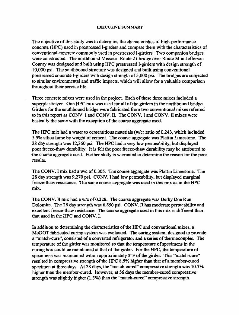
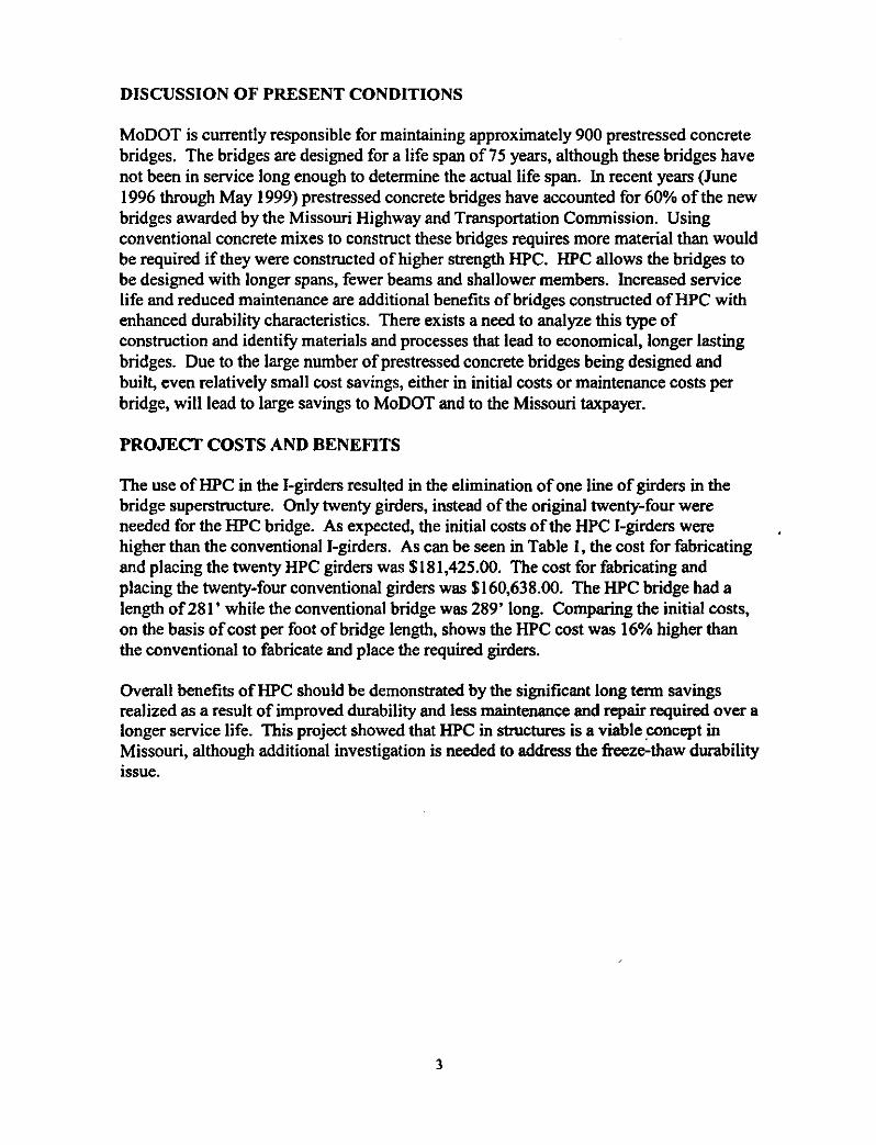
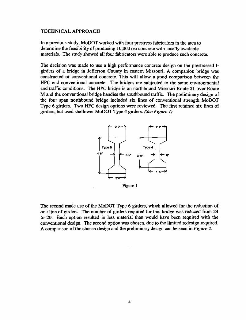
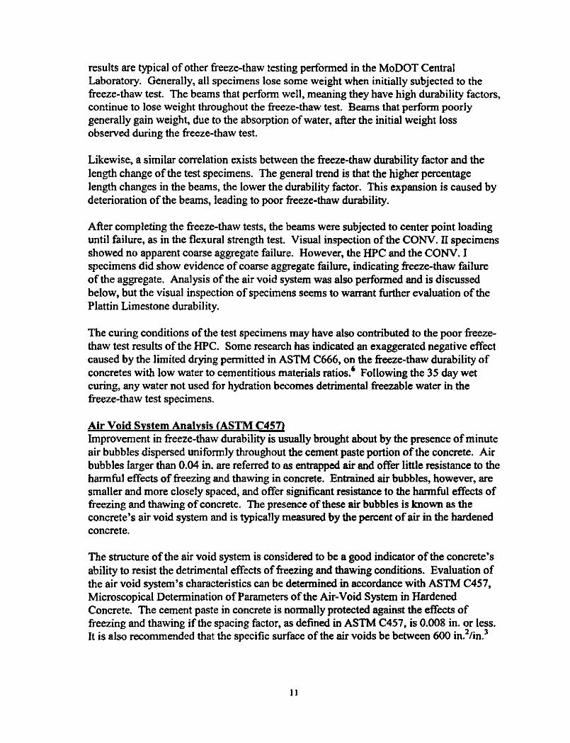
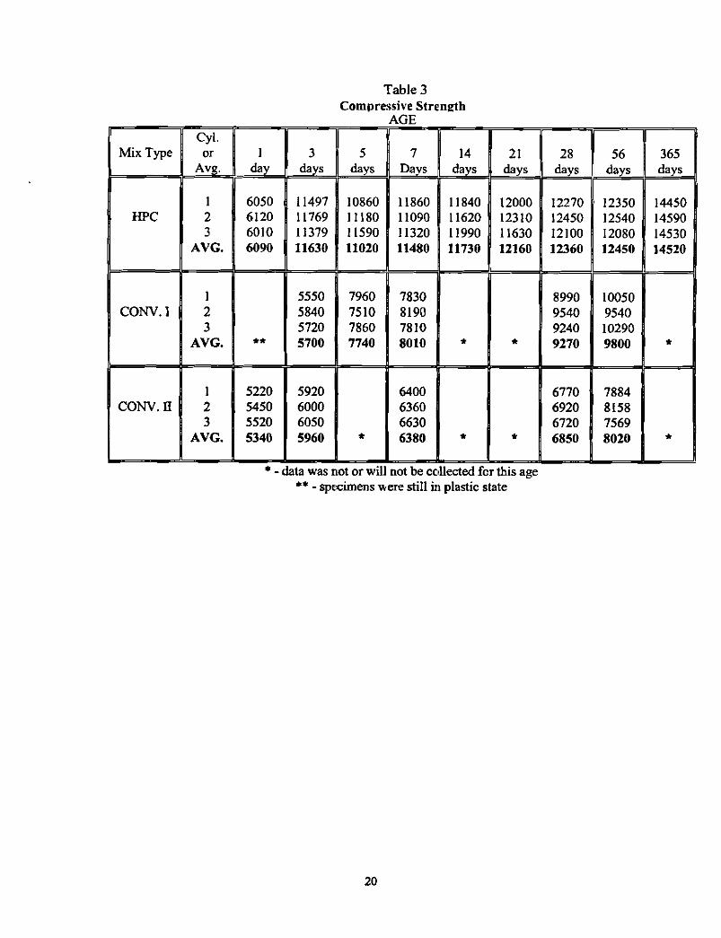

94
CONV I Curing Temperatures at Girder Ends
North End mm-q
South End-
12 18 24 30
Cumulative Time From Pour (hours)
CONV II Curing Temperatures at Girder Ends
North End rWV
South End-
95 1 I 0 6 12 18 24
Cumulative Time From Pour (hours)

CONV II Curing Temperatures at Girder Ends
North End rWV
South End-
95 1 I 0 6 12 18 24
Cumulative Time From Pour (hours)