Deterioration of concrete - Thomas · PDF fileDeterioration of concrete ... concrete made with...
32
Chapter 1 Deterioration of concrete Contents Corrosion damage to reinforced concrete . . . . . . . . . . . . . . . . . . . . . . . . . . . . . . . . 2 Manifestations of corrosion damage . . . . . . . . . . . . . . . . . . . . . . . . . . . . . . . . . . . . . . 2 Condition surveys of reinforcement corrosion . . . . . . . . . . . . . . . . . . . . . . . . . . . . . 7 Visual assessments . . . . . . . . . . . . . . . . . . . . . . . . . . . . . . . . . . . . . . . . . . . . . . . . . . . 7 Chloride testing . . . . . . . . . . . . . . . . . . . . . . . . . . . . . . . . . . . . . . . . . . . . . . . . . . . . . 7 Carbonation depth . . . . . . . . . . . . . . . . . . . . . . . . . . . . . . . . . . . . . . . . . . . . . . . . . 12 Rebar potentials . . . . . . . . . . . . . . . . . . . . . . . . . . . . . . . . . . . . . . . . . . . . . . . . . . . . 12 Resistivity . . . . . . . . . . . . . . . . . . . . . . . . . . . . . . . . . . . . . . . . . . . . . . . . . . . . . . . . . 13 Corrosion rate measurements . . . . . . . . . . . . . . . . . . . . . . . . . . . . . . . . . . . . . . . . 14 Repair strategies . . . . . . . . . . . . . . . . . . . . . . . . . . . . . . . . . . . . . . . . . . . . . . . . . . . . . . 14 Patch repairs . . . . . . . . . . . . . . . . . . . . . . . . . . . . . . . . . . . . . . . . . . . . . . . . . . . . . . . 15 Migrating corrosion inhibitors . . . . . . . . . . . . . . . . . . . . . . . . . . . . . . . . . . . . . . . 19 Electrochemical techniques . . . . . . . . . . . . . . . . . . . . . . . . . . . . . . . . . . . . . . . . . . 19 Cathodic protection systems . . . . . . . . . . . . . . . . . . . . . . . . . . . . . . . . . . . . . . . . . 21 Demolition or reconstruction . . . . . . . . . . . . . . . . . . . . . . . . . . . . . . . . . . . . . . . . 22 Alkali–aggregate reaction . . . . . . . . . . . . . . . . . . . . . . . . . . . . . . . . . . . . . . . . . . . . . . 22 Types of alkali–aggregate reaction . . . . . . . . . . . . . . . . . . . . . . . . . . . . . . . . . . . . . . . 22 Alkali–silica reaction . . . . . . . . . . . . . . . . . . . . . . . . . . . . . . . . . . . . . . . . . . . . . . . . 22 Alkali–carbonate rock reaction . . . . . . . . . . . . . . . . . . . . . . . . . . . . . . . . . . . . . . . 22 Recognition of alkali–aggregate reaction . . . . . . . . . . . . . . . . . . . . . . . . . . . . . . . . . 22 Cracking of concrete . . . . . . . . . . . . . . . . . . . . . . . . . . . . . . . . . . . . . . . . . . . . . . . . 23 Expansion of concrete members . . . . . . . . . . . . . . . . . . . . . . . . . . . . . . . . . . . . . . 23 Presence of gel . . . . . . . . . . . . . . . . . . . . . . . . . . . . . . . . . . . . . . . . . . . . . . . . . . . . . 23 Discoloration . . . . . . . . . . . . . . . . . . . . . . . . . . . . . . . . . . . . . . . . . . . . . . . . . . . . . . . 23 Confirmation of alkali–aggregate reaction . . . . . . . . . . . . . . . . . . . . . . . . . . . . . . . . 23 Conditions necessary for alkali–aggregate reaction . . . . . . . . . . . . . . . . . . . . . . . . 24 High alkalinity of pore solution . . . . . . . . . . . . . . . . . . . . . . . . . . . . . . . . . . . . . . 24 Reactive phases in the aggregate . . . . . . . . . . . . . . . . . . . . . . . . . . . . . . . . . . . . . 24 Environmental conditions . . . . . . . . . . . . . . . . . . . . . . . . . . . . . . . . . . . . . . . . . . . 24 Preventive measures . . . . . . . . . . . . . . . . . . . . . . . . . . . . . . . . . . . . . . . . . . . . . . . . . . . 24 Remedial action . . . . . . . . . . . . . . . . . . . . . . . . . . . . . . . . . . . . . . . . . . . . . . . . . . . . . . . 25 Reaction dormant . . . . . . . . . . . . . . . . . . . . . . . . . . . . . . . . . . . . . . . . . . . . . . . . . . 25 Reaction active . . . . . . . . . . . . . . . . . . . . . . . . . . . . . . . . . . . . . . . . . . . . . . . . . . . . . 25 1
-
Upload
nguyendieu -
Category
Documents
-
view
217 -
download
0
Transcript of Deterioration of concrete - Thomas · PDF fileDeterioration of concrete ... concrete made with...

Chapter 1
Deterioration of concrete
Contents
Corrosion damage to reinforced concrete . . . . . . . . . . . . . . . . . . . . . . . . . . . . . . . . 2Manifestations of corrosion damage . . . . . . . . . . . . . . . . . . . . . . . . . . . . . . . . . . . . . . 2Condition surveys of reinforcement corrosion . . . . . . . . . . . . . . . . . . . . . . . . . . . . . 7
Visual assessments . . . . . . . . . . . . . . . . . . . . . . . . . . . . . . . . . . . . . . . . . . . . . . . . . . . 7Chloride testing . . . . . . . . . . . . . . . . . . . . . . . . . . . . . . . . . . . . . . . . . . . . . . . . . . . . . 7Carbonation depth . . . . . . . . . . . . . . . . . . . . . . . . . . . . . . . . . . . . . . . . . . . . . . . . . 12Rebar potentials . . . . . . . . . . . . . . . . . . . . . . . . . . . . . . . . . . . . . . . . . . . . . . . . . . . . 12Resistivity . . . . . . . . . . . . . . . . . . . . . . . . . . . . . . . . . . . . . . . . . . . . . . . . . . . . . . . . . 13Corrosion rate measurements . . . . . . . . . . . . . . . . . . . . . . . . . . . . . . . . . . . . . . . . 14
Repair strategies . . . . . . . . . . . . . . . . . . . . . . . . . . . . . . . . . . . . . . . . . . . . . . . . . . . . . . 14Patch repairs . . . . . . . . . . . . . . . . . . . . . . . . . . . . . . . . . . . . . . . . . . . . . . . . . . . . . . . 15Migrating corrosion inhibitors . . . . . . . . . . . . . . . . . . . . . . . . . . . . . . . . . . . . . . . 19Electrochemical techniques . . . . . . . . . . . . . . . . . . . . . . . . . . . . . . . . . . . . . . . . . . 19Cathodic protection systems . . . . . . . . . . . . . . . . . . . . . . . . . . . . . . . . . . . . . . . . . 21Demolition or reconstruction . . . . . . . . . . . . . . . . . . . . . . . . . . . . . . . . . . . . . . . . 22
Alkali–aggregate reaction . . . . . . . . . . . . . . . . . . . . . . . . . . . . . . . . . . . . . . . . . . . . . . 22Types of alkali–aggregate reaction . . . . . . . . . . . . . . . . . . . . . . . . . . . . . . . . . . . . . . . 22
Alkali–silica reaction . . . . . . . . . . . . . . . . . . . . . . . . . . . . . . . . . . . . . . . . . . . . . . . . 22Alkali–carbonate rock reaction . . . . . . . . . . . . . . . . . . . . . . . . . . . . . . . . . . . . . . . 22
Recognition of alkali–aggregate reaction . . . . . . . . . . . . . . . . . . . . . . . . . . . . . . . . . 22Cracking of concrete . . . . . . . . . . . . . . . . . . . . . . . . . . . . . . . . . . . . . . . . . . . . . . . . 23Expansion of concrete members . . . . . . . . . . . . . . . . . . . . . . . . . . . . . . . . . . . . . . 23Presence of gel . . . . . . . . . . . . . . . . . . . . . . . . . . . . . . . . . . . . . . . . . . . . . . . . . . . . . 23Discoloration . . . . . . . . . . . . . . . . . . . . . . . . . . . . . . . . . . . . . . . . . . . . . . . . . . . . . . . 23
Confirmation of alkali–aggregate reaction . . . . . . . . . . . . . . . . . . . . . . . . . . . . . . . . 23Conditions necessary for alkali–aggregate reaction . . . . . . . . . . . . . . . . . . . . . . . . 24
High alkalinity of pore solution . . . . . . . . . . . . . . . . . . . . . . . . . . . . . . . . . . . . . . 24Reactive phases in the aggregate . . . . . . . . . . . . . . . . . . . . . . . . . . . . . . . . . . . . . 24Environmental conditions . . . . . . . . . . . . . . . . . . . . . . . . . . . . . . . . . . . . . . . . . . . 24
Preventive measures . . . . . . . . . . . . . . . . . . . . . . . . . . . . . . . . . . . . . . . . . . . . . . . . . . . 24Remedial action . . . . . . . . . . . . . . . . . . . . . . . . . . . . . . . . . . . . . . . . . . . . . . . . . . . . . . . 25
Reaction dormant . . . . . . . . . . . . . . . . . . . . . . . . . . . . . . . . . . . . . . . . . . . . . . . . . . 25Reaction active . . . . . . . . . . . . . . . . . . . . . . . . . . . . . . . . . . . . . . . . . . . . . . . . . . . . . 25
1
Chapter 1.qxd 18/10/2002 15:44 Page 1

2
Chemical attack on concrete . . . . . . . . . . . . . . . . . . . . . . . . . . . . . . . . . . . . . . . . . . . 25Soft water . . . . . . . . . . . . . . . . . . . . . . . . . . . . . . . . . . . . . . . . . . . . . . . . . . . . . . . . . . . . 26
Attack mechanism . . . . . . . . . . . . . . . . . . . . . . . . . . . . . . . . . . . . . . . . . . . . . . . . . . 26Remedial action . . . . . . . . . . . . . . . . . . . . . . . . . . . . . . . . . . . . . . . . . . . . . . . . . . . . 26
Sulphates . . . . . . . . . . . . . . . . . . . . . . . . . . . . . . . . . . . . . . . . . . . . . . . . . . . . . . . . . . . . 26Attack mechanism . . . . . . . . . . . . . . . . . . . . . . . . . . . . . . . . . . . . . . . . . . . . . . . . . . 26Remedial action . . . . . . . . . . . . . . . . . . . . . . . . . . . . . . . . . . . . . . . . . . . . . . . . . . . . 27
Fire damage . . . . . . . . . . . . . . . . . . . . . . . . . . . . . . . . . . . . . . . . . . . . . . . . . . . . . . . . . . 28Effect of high temperatures . . . . . . . . . . . . . . . . . . . . . . . . . . . . . . . . . . . . . . . . . . . . . 28Remedial action . . . . . . . . . . . . . . . . . . . . . . . . . . . . . . . . . . . . . . . . . . . . . . . . . . . . . . . 28Frost attack . . . . . . . . . . . . . . . . . . . . . . . . . . . . . . . . . . . . . . . . . . . . . . . . . . . . . . . . . . . 28Damage mechanism . . . . . . . . . . . . . . . . . . . . . . . . . . . . . . . . . . . . . . . . . . . . . . . . . . . 28Remedial action . . . . . . . . . . . . . . . . . . . . . . . . . . . . . . . . . . . . . . . . . . . . . . . . . . . . . . . 29Dimensional change . . . . . . . . . . . . . . . . . . . . . . . . . . . . . . . . . . . . . . . . . . . . . . . . . . 29Shrinkage and creep . . . . . . . . . . . . . . . . . . . . . . . . . . . . . . . . . . . . . . . . . . . . . . . . . . . 30
Drying shrinkage . . . . . . . . . . . . . . . . . . . . . . . . . . . . . . . . . . . . . . . . . . . . . . . . . . . 30Carbonation shrinkage . . . . . . . . . . . . . . . . . . . . . . . . . . . . . . . . . . . . . . . . . . . . . . 30Creep . . . . . . . . . . . . . . . . . . . . . . . . . . . . . . . . . . . . . . . . . . . . . . . . . . . . . . . . . . . . . 30
Thermal expansion . . . . . . . . . . . . . . . . . . . . . . . . . . . . . . . . . . . . . . . . . . . . . . . . . . . . 30Remedial action . . . . . . . . . . . . . . . . . . . . . . . . . . . . . . . . . . . . . . . . . . . . . . . . . . . . . . . 31Further reading . . . . . . . . . . . . . . . . . . . . . . . . . . . . . . . . . . . . . . . . . . . . . . . . . . . . . . . 31
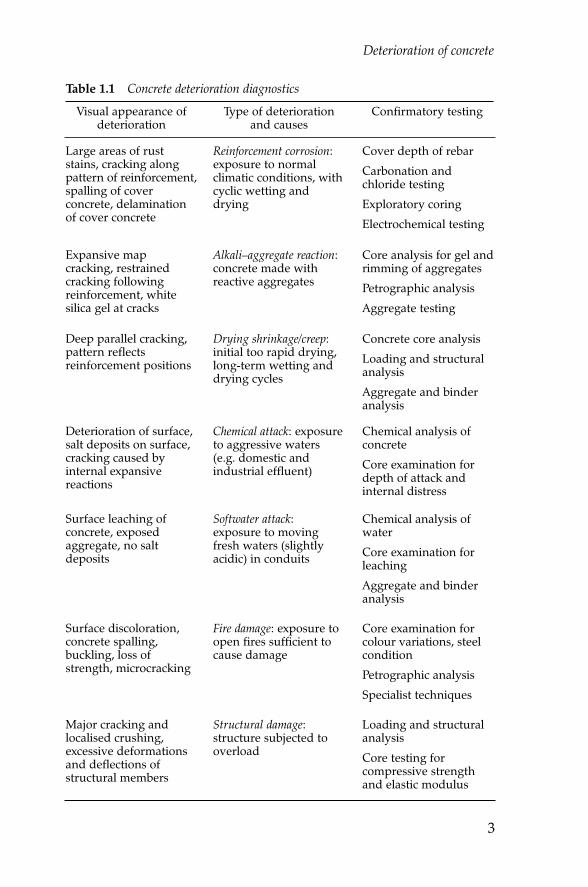
The dominant cause for failure of concrete in structures is corrosion ofthe reinforcing steel. The other causes are less common, but still critical,agents of material failure. It is important to constantly bear in mind thatthe failure of concrete structures can seldom be ascribed eitherexclusively to the failure of a material component (cement, aggregate orreinforcement) or exclusively to failure of the system (structural ordesign failure). The reasons why concrete deteriorates are summarised inTable 1.1.
Corrosion damage to reinforced concrete
Manifestations of corrosion damage
Reinforcement corrosion is the major cause of deterioration of concretestructures. Corrosion results in a volume increase of the steel of up to tentimes its original volume due to the formation of hydrated oxides. Thisexpansion of the steel results in mechanical disruption of the encasingconcrete.
Reinforcement corrosion is particularly pernicious in that damage mayoccur rapidly and repairs are invariably expensive. Furthermore, by the
Deterioration and failure of building materials
Chapter 1.qxd 18/10/2002 15:44 Page 2
Deterioration of concrete
3
Table 1.1 Concrete deterioration diagnostics
Large areas of ruststains, cracking alongpattern of reinforcement,spalling of coverconcrete, delaminationof cover concrete
Reinforcement corrosion:exposure to normalclimatic conditions, withcyclic wetting anddrying
Cover depth of rebar
Carbonation andchloride testing
Exploratory coring
Electrochemical testing
Expansive mapcracking, restrainedcracking followingreinforcement, whitesilica gel at cracks
Alkali–aggregate reaction:concrete made withreactive aggregates
Core analysis for gel andrimming of aggregates
Petrographic analysis
Aggregate testing
Deep parallel cracking,pattern reflectsreinforcement positions
Drying shrinkage/creep:initial too rapid drying,long-term wetting anddrying cycles
Concrete core analysis
Loading and structuralanalysis
Aggregate and binderanalysis
Deterioration of surface,salt deposits on surface,cracking caused byinternal expansivereactions
Chemical attack: exposureto aggressive waters(e.g. domestic andindustrial effluent)
Chemical analysis ofconcrete
Core examination fordepth of attack andinternal distress
Surface leaching ofconcrete, exposedaggregate, no saltdeposits
Softwater attack:exposure to movingfresh waters (slightlyacidic) in conduits
Chemical analysis ofwater
Core examination forleaching
Aggregate and binderanalysis
Surface discoloration,concrete spalling,buckling, loss ofstrength, microcracking
Fire damage: exposure toopen fires sufficient tocause damage
Core examination forcolour variations, steelcondition
Petrographic analysis
Specialist techniques
Major cracking andlocalised crushing,excessive deformationsand deflections ofstructural members
Structural damage:structure subjected tooverload
Loading and structuralanalysis
Core testing forcompressive strengthand elastic modulus
Visual appearance ofdeterioration
Type of deteriorationand causes
Confirmatory testing
Chapter 1.qxd 18/10/2002 15:44 Page 3

Deterioration and failure of building materials
4
Tabl
e 1.
2C
ondi
tions
and
feat
ures
of r
einf
orce
men
t cor
rosi
on
Chl
orid
e in
duce
dM
arin
e en
viro
nmen
ts
Indu
stri
al c
hem
ical
s
Adm
ixed
chl
orid
es (o
lder
str
uctu
res)
Dis
tinct
inte
nse
anod
e an
d ca
thod
e re
gion
s
Rap
id a
nd s
ever
e lo
calis
ed p
ittin
g co
rros
ion
and
dam
age
tosu
rrou
ndin
g co
ncre
te
Cor
rosi
on d
amag
e af
fect
ing
stru
ctur
al in
tegr
ity m
ay b
e fa
rad
vanc
ed b
efor
e be
ing
notic
ed (s
urfa
ce s
tain
s, c
rack
ing,
spa
lling
)
Mor
e pe
rnic
ious
and
diff
icul
t to
trea
t tha
n ca
rbon
atio
n-in
duce
dco
rros
ion
Car
bona
tion
indu
ced
Uns
atur
ated
con
cret
e
Pollu
ted
envi
ronm
ents
Low
cov
er d
epth
s to
ste
el
Gen
eral
cor
rosi
on w
ith m
ultip
le p
ittin
g al
ong
reba
rs
Mod
erat
e co
rros
ion
rate
s, e
xcep
t whe
n w
et a
nd d
ry fa
ces
are
near
to e
ach
othe
r
Cor
rosi
on d
amag
e ea
sily
not
iced
(sur
face
sta
ins,
cra
ckin
g,sp
allin
g); g
ener
ally
onl
y af
fect
s ae
sthe
tics
Req
uire
s a
diff
eren
t rep
air
appr
oach
from
chl
orid
e-in
duce
dco
rros
ion;
rep
airs
are
gen
eral
ly s
ucce
ssfu
l
Type
of c
orro
sion
Envi
ronm
ent o
r ca
usat
ive
cond
ition
sSi
gnifi
cant
feat
ures
of d
eter
iora
tion
Stra
y cu
rren
tD
C p
ower
sup
plie
s
Rai
lway
sys
tem
s
Hea
vy in
dust
ry, s
mel
ters
Gen
eral
cor
rosi
on o
f reb
ar e
xpos
ed to
moi
st c
ondi
tions
Cor
rosi
on n
ot c
onfin
ed to
low
cov
er d
epth
s
Larg
e cr
ack
wid
ths
poss
ible
Chapter 1.qxd 18/10/2002 15:44 Page 4

Deterioration of concrete
5
Seco
ndar
y fo
rms
Prim
ary
crac
king
due
toal
kali–
aggr
egat
e re
actio
n, d
elay
edet
trin
gite
form
atio
n, s
truc
tura
lcr
acki
ng
Cor
rosi
on lo
calis
ed in
reg
ions
whe
re c
rack
s in
ters
ect t
he r
ebar
Oth
er fo
rms
of d
istr
ess
evid
ent i
n co
ncre
te (i
.e. a
lkal
i–ag
greg
ate
reac
tion
gel d
epos
its)
Che
mic
al in
duce
dSu
lpha
te in
gro
undw
ater
Fert
ilise
r fa
ctor
ies
Indu
stri
al p
lant
s
Sew
age
trea
tmen
t wor
ks
Cor
rosi
on g
ener
ally
ass
ocia
ted
with
nea
r-sa
tura
ted
cond
ition
s
Con
cret
e de
teri
orat
ion
occu
rrin
g to
geth
er w
ith c
orro
sion
Art
ifici
ally
indu
ced
Bim
etal
lic c
orro
sion
Part
ial s
ealin
g of
con
cret
e
Hig
h te
mpe
ratu
res
(>20
0°C
)
Patc
h re
pair
s of
cor
rosi
on
Gen
eral
ly v
ery
loca
lised
inte
nse
corr
osio
n du
e to
wel
l-def
ined
anod
e/ca
thod
e re
gion
s
Chapter 1.qxd 18/10/2002 15:44 Page 5

Deterioration and failure of building materials
6
time visible corrosion damage is noticed, structural integrity may alreadybe compromised. There are two major consequences of reinforcementcorrosion:
• cracking and spalling of the cover concrete as a result of theformation of the corrosion products
• a reduction of cross-sectional area of the rebar by pitting (a problemin prestressed concrete structures).
See also:Metal, Corrosion, p. 34Metal, Corrosion of steel embedded in concrete, p. 39
Unfortunately, most reinforced concrete structures that exhibitcracking and spalling have gone beyond the point where simple, cost-effective measures can be taken to restore durability. Condition surveys aretherefore an important strategy for identifying and quantifying the stateof corrosion of a structure over time. The results of such surveys willdetermine the most appropriate repair strategy.
The features of reinforcement corrosion induced by differentconditions are summarised in Table 1.2 and the factors that influence themanifestation of reinforcement corrosion are listed in Table 1.3. Figure 1.1illustrates the three stages in the development of corrosion of reinforcedconcrete structures.
Initiation period
No evidenceof damage
Corrosion initiated bychlorides or carbonation
Corrosion withminor damage
Widespread crackingand spalling of cover
Age of structure (years)
Ext
ent o
f dam
age
0 15 30
Propagation period Accelerated period
Figure 1.1 The three-stage model of corrosion damage
Chapter 1.qxd 18/10/2002 15:44 Page 6
Deterioration of concrete
7
Condition surveys of reinforcement corrosion
A detailed corrosion or condition survey is vital in order to identify theexact cause and extent of deterioration, before repair options areconsidered. Unfortunately, most reinforced concrete structures thatexhibit cracking and spalling have gone beyond the point where simple,cost-effective measures can be taken to restore durability. Conditionsurveys are therefore an important strategy for identifying andquantifying the state of corrosion of a structure over time. The results ofsuch surveys will determine the most appropriate repair strategy. Thevarious survey techniques are summarised in Table 1.4.
Visual assessmentsItems that should be included in a checklist for a visual assessment ofconcrete degradation are listed in Table 1.5. Visual assessment ofdeterioration may come too late for cost-effective repairs because rebarcorrosion damage often only fully manifests itself at the surface aftersignificant deterioration has occurred.
Chloride testingChlorides exist in concrete as both bound and free ions, but only freechlorides directly affect corrosion. Measuring free water-soluble chloridesaccurately is extremely difficult, and chlorides are therefore most
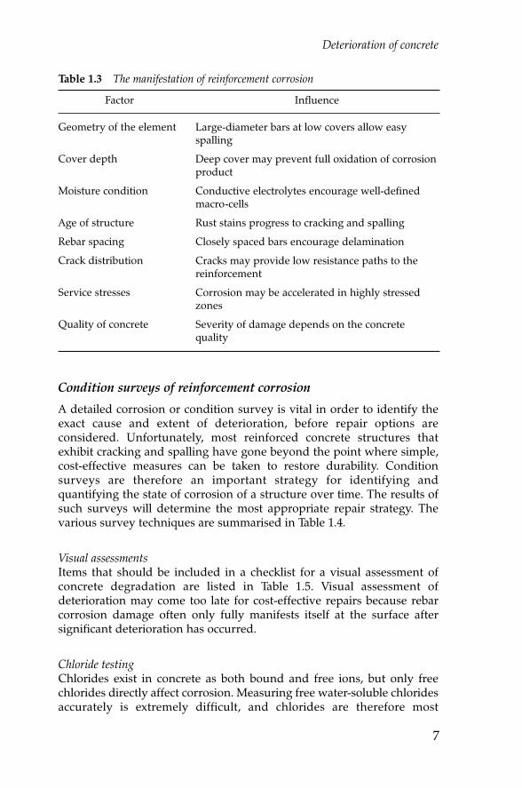
Table 1.3 The manifestation of reinforcement corrosion
Geometry of the element
Cover depth
Moisture condition
Age of structure
Rebar spacing
Crack distribution
Service stresses
Quality of concrete
Large-diameter bars at low covers allow easyspalling
Deep cover may prevent full oxidation of corrosionproduct
Conductive electrolytes encourage well-definedmacro-cells
Rust stains progress to cracking and spalling
Closely spaced bars encourage delamination
Cracks may provide low resistance paths to thereinforcement
Corrosion may be accelerated in highly stressedzones
Severity of damage depends on the concretequality
Factor Influence
Chapter 1.qxd 18/10/2002 15:44 Page 7

Deterioration and failure of building materials
8
Tabl
e 1.
4C
ondi
tion
surv
eys
to e
valu
ate
rein
forc
emen
t cor
rosi
on
Visu
al: u
se c
ompr
ehen
sive
che
cklis
tC
orro
sion
dur
ing
earl
y st
ages
not
vis
ible
Vis
ual s
urve
y fir
st a
ctio
n of
det
aile
d in
vest
igat
ion
Cov
er s
urve
ys: u
se a
ltern
atin
gm
agne
tic fi
eld
to lo
cate
pos
ition
of
stee
l in
conc
rete
Unr
elia
ble
whe
n:
–re
bar
clos
ely
spac
ed, d
iffer
ent t
ypes
/siz
es, a
t dee
p co
ver
–si
te-s
peci
fic c
alib
ratio
ns n
ot d
one
–ot
her
mag
netic
mat
eria
l nea
rby
(win
dow
s, b
olts
, con
duits
)
(Not
e: a
uste
nitic
sta
inle
ss s
teel
s ar
e no
n-m
agne
tic)
Del
amin
atio
n: h
amm
er o
r ch
ain
drag
Oft
en u
nder
estim
ate
full
exte
nt o
f del
amin
atio
n an
d in
tern
al c
rack
ing
Not
def
initi
ve
Surv
eys
Com
men
ts
Chl
orid
e te
stin
g: c
hem
ical
ana
lysi
sC
hlor
ides
in a
ggre
gate
s gi
ve m
isle
adin
g re
sults
Chl
orid
es in
cra
cks
or d
efec
ts d
iffic
ult t
o de
term
ine
accu
rate
ly
Slag
, con
cret
es d
iffic
ult t
o an
alys
e
Larg
e sa
mpl
es r
equi
red
to a
llow
for
the
pres
ence
of a
ggre
gate
s
Chapter 1.qxd 18/10/2002 15:44 Page 8

Deterioration of concrete
9
Car
bona
tion
dept
h: c
hem
ical
met
hod
(pH
indi
cato
r)Sl
ight
ly u
nder
estim
ates
car
bona
tion
dept
h
Diff
icul
t to
disc
ern
colo
ur c
hang
e ca
used
by
pH in
dica
tor
in d
ark-
colo
ured
con
cret
e
Indi
cato
r in
effe
ctiv
e at
ver
y hi
gh p
H le
vels
(e.g
. aft
er e
lect
roch
emic
al r
e-al
kalis
atio
n)
Test
ing
mus
t be
done
onl
y on
ver
y fr
eshl
y ex
pose
d co
ncre
te s
urfa
ces
(bef
ore
atm
osph
eric
carb
onat
ion
occu
rs)
Reb
ar p
oten
tials
: pot
entio
met
er(v
oltm
eter
) usi
ng c
oppe
r/co
pper
sulp
hate
ref
eren
ce e
lect
rode
Not
rec
omm
ende
d fo
r ca
rbon
atio
n-in
duce
d co
rros
ion
Inte
rpre
tatio
n is
a s
peci
alis
t tas
k
Del
amin
atio
n co
uld
disr
upt p
oten
tial f
ield
, and
thus
pro
duce
fals
e re
adin
gs
Envi
ronm
enta
l eff
ects
(tem
pera
ture
, hum
idity
) inf
luen
ce p
oten
tials
No
dire
ct c
orre
latio
n be
twee
n re
bar
pote
ntia
l and
cor
rosi
on r
ates
Stra
y cu
rren
ts in
fluen
ce m
easu
red
pote
ntia
ls
Res
istiv
ity: W
enne
r pr
obes
and
resi
stiv
ity m
eter
Car
bona
tion
and
wet
ting
fron
ts a
ffec
t mea
sure
men
ts
Con
cret
e w
ith h
igh
cont
act r
esis
tanc
e at
sur
face
res
ults
in u
nsta
ble
read
ings
Reb
ar d
irec
tly b
elow
pro
be in
fluen
ces
read
ings
Cor
rosi
on r
ate:
line
ar p
olar
isat
ion
resi
stan
ce (g
alva
nost
atic
line
arpo
lari
satio
n re
sist
ance
with
gua
rd-
ring
sen
sor)
Soph
istic
ated
tech
niqu
e, r
equi
res
cons
ider
able
exp
ertis
e to
ope
rate
Envi
ronm
enta
l and
mat
eria
l con
ditio
ns h
ave
larg
e in
fluen
ce o
n m
easu
rem
ents
and
sin
gle
read
ings
are
gen
eral
ly u
nrel
iabl
e
Chapter 1.qxd 18/10/2002 15:44 Page 9

Deterioration and failure of building materials
10
commonly determined as acid soluble or total chlorides in accordancewith the appropriate national standard.
Chloride sampling and the determination of the chloride level in concreteare illustrated in Figure 1.2 and are usually done in the following manner:
1. Concrete samples are extracted as either core or drilled powder samples.2. Depth increments are chosen depending on the cover to steel and the
likely level of chloride contamination (increments are typicallybetween 5 and 25 mm).
3. Dry powder samples are digested in diluted nitric acid to release allchlorides.
Table 1.5 Visual assessment of structural failure: items for checklist
Background data
Identification
Environment
History
Reference, number, location
Severity and type of exposure
Age, design data, repairs
Original condition
Surface condition
Early cracking
Concrete quality
Rebar cover
Structural effects
Honeycombing, bleeding, voids, pop-outs
Plastic settlement or plastic shrinkage
Surface hardness, density, voids, colour
Covermeter survey, mechanical breakout
Overloading, dynamic effects, structural cracking
Present condition
Surface damage
Staining
Cracking
Joint deficiencies
Rebar condition
Carbonation
Delamination
Previous repairs
Abrasion, staining, chemical attack, spalling, leaching
Rebar corrosion, alkali–aggregate reaction gel,efflorescence, salts
Width, pattern, location, causes of cracking
Joint spalls, vertical and lateral movements, seal damage
Visual examination of bar, rust and pitting damage
Indicator test on cores or mechanical breakouts
Size, frequency, severity of delamination
Integrity of repairs, signs of damage near repairlocations
Item Details
Chapter 1.qxd 18/10/2002 15:44 Page 10

Deterioration of concrete
11
4. Chlorides are analysed using potentiometric titration or the Volardmethod.
5. Chloride contents should preferably be expressed as a percentage bymass of cement.
6. Chloride profiles may be drawn such that chloride concentrationsmay be interpolated or extrapolated for any depth.
7. Future chloride levels can be estimated from Fick’s second law ofdiffusion.
The corrosion threshold depends on several factors, including concretequality, cover depth and saturation level of the concrete. The probability ofcorrosion may be assessed from the qualitative rating shown in Table 1.6for acid-soluble chloride contents.
Figure 1.2 Determination of chloride content
ANALYSISSAMPLING
Slices
Core surface
Chl
orid
e co
nten
t
1 2 3 4 5 6
Slices1 2 3 4 5 6
Table 1.6 Qualitative risk of corrosion based on chloride levels
Chloride content by mass ofcement (mass %)
Probability of corrosion
<0.40.4–1.0>1.0
LowModerate
High
Chapter 1.qxd 18/10/2002 15:44 Page 11

Deterioration and failure of building materials
12
Carbonation depthCarbonation depth is measured by spraying a fresh fracture surface of theconcrete with a phenolphthalein indicator solution (1% by mass inethanol/water solution). Phenolphthalein remains clear where concrete iscarbonated but turns pink/purple where concrete is still strongly alkaline(pH > 9.0). Carbonation moves through concrete as a distinct front andreduces the natural alkalinity of concrete from a pH in excess of 12.5 toapproximately 8.3. Steel starts to depassivate when the alkalinity isreduced below pH 10.5. The progress of the carbonation front is shownin Figure 1.3. For prediction purposes, the rate of carbonation isapproximately proportional to the square root of time.
Environmental conditions most favourable for carbonation (i.e.50–65% relative humidity (RH)) are usually too dry to allow rapid steelcorrosion, which normally requires humidity levels above 80% RH.Structures exposed to fluctuations in moisture conditions of the coverconcrete, such as may occur during rainy spells, are however vulnerableto carbonation-induced corrosion.
Rebar potentialsChloride-induced corrosion of steel is associated with anodic and cathodicareas along the rebar with consequent changes in the electropotential ofthe steel. It is possible to measure these rebar potentials at different pointsand plot the results in the form of a potential map. Measurement of rebarpotentials may determine the thermodynamic risk of corrosion, butcannot evaluate the kinetics of the reaction. Rebar potentials are normallydetermined in accordance with ASTM C876: 1991 using a copper/copper
pH ~ 12.5
pH ~ 8.3
pH ~ 9.0
Carbonationfront
CarbonatedClear colour
Sliced core
Sur
face Alkalinity profile
UncarbonatedPink/purple colour
Figure 1.3 The progress of the carbonation front
Chapter 1.qxd 18/10/2002 15:44 Page 12

Deterioration of concrete
13
sulphate reference electrode connected to a hand-held voltmeter. Thequalitative risk of corrosion based on rebar potentials is given in Table 1.7.Note that the technique is not recommended for carbonation-inducedcorrosion where clearly defined anodic regions are absent.
The procedure for undertaking a rebar potential survey is as follows:
1. Mark up a grid pattern in the area of measurement (not more than500 mm centres).
2. Make an electrical connection to clean steel by coring or breaking outconcrete.
3. Use a multimeter to check that the steel is electrically continuous overthe survey area.
4. Wet the concrete surface with tap water if the concrete appears to bedry.
5. Take and record readings either manually or by using a data logger.6. Check the data on site to ensure these correlate with the visual signs
of corrosion.
Rebar potential measurements are relatively quick to perform.Absolute values are often of lesser importance than are the differencesbetween values measured on a structure. A shift of several hundredmillivolts over a short distance of 300–500 mm often indicates a high riskof corrosion.
ResistivityConcrete resistivity controls the rate at which steel corrodes in concreteonce favourable conditions for corrosion exist. Resistivity is dependent onthe moisture condition of the concrete, on the permeability andinterconnectivity of the pore structure, and on the concentration of ionicspecies in the pore water of concrete.
• poor quality, saturated concrete has low resistivity (e.g. <10 kΩ-cm)• high-quality, dry concrete has high resistivity (e.g. >25 kΩ-cm).
Resistivity measurements are simple to perform on site and are donewith a Wenner probe connected to a portable resistivity meter. The outer
Table 1.7 Qualitative risk of chloride-induced corrosion
Rebar potential(-mV Cu/CuSO4)
Qualitative risk of corrosion
<200200–350
>350
LowUncertain
High
Chapter 1.qxd 18/10/2002 15:44 Page 13

Deterioration and failure of building materials
14
two probes send an alternating current through the concrete, while theinner two probes measure the potential difference in the concrete. Oncethe concrete resistivity is known, a rough assessment of likely corrosionrates can be made as shown in Table 1.8. This assessment assumes thatconditions are favourable for corrosion.
Corrosion rate measurementsCorrosion rate measurements are the only reliable method of measuringactual corrosion activity in reinforced concrete. A number of sophisticatedcorrosion monitoring systems are available, based primarily on linearpolarisation resistance (LPR) principles. Corrosion rate measurements onfield structures are most commonly done using galvanostatic LPRtechniques with a guard-ring type sensor to confine the area of steelunder test. Table 1.9 shows a qualitative guide for the assessment ofcorrosion rates of site structures.
Repair strategies
Repair of reinforced concrete structures needs to be undertaken in arational manner to guarantee success. An increasing number of repairoptions are available that must be considered in terms of cost, technicalfeasibility and reliability. Engineers need to understand all the relevantmaterial, structural and environmental issues associated with concreterepairs in order to make intelligent choices.
Table 1.8 Likely corrosion rate based on concrete resistivity
Resistivity (kΩ-cm) Likely corrosion rate for givencorrosive conditions
<1212–20>20
HighModerate
Low
Table 1.9 Qualitative assessment of corrosion rate measurements
Corrosion rate (µA/cm2) Qualitative assessment of corrosion rate
>101.0–100.2–1.0<0.2
HighModerate
LowPassive
Chapter 1.qxd 18/10/2002 15:44 Page 14

Deterioration of concrete
15
Various factors determine the suitability and cost-effectiveness ofrepairs:
• level of deterioration• specific conditions of the structure• environmental conditions.
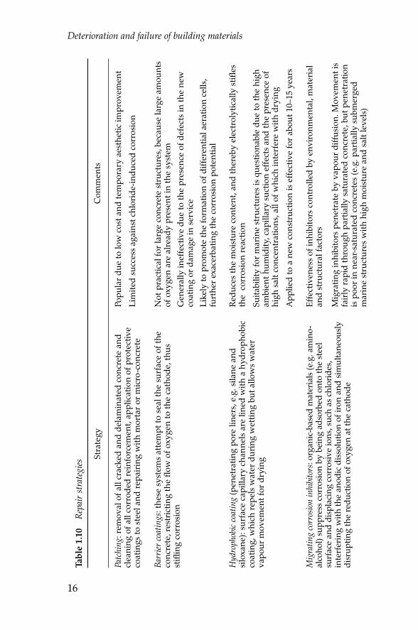
Therefore, high-quality repairs require a thorough investigation of thecauses of deterioration, appropriate repair specifications and competentexecution of the repair work. This can only be done when independentexperts carry out structural investigations, engineers with specialist repairexpertise draw up specifications and competent contractors undertakerepairs. The various repair options are compared in Table 1.10.
Patch repairsThe approach to repairing damaged concrete structures depends onwhether the corrosion is carbonation induced or chloride induced. Thetwo types of corrosion are contrasted in Table 1.11.
Important aspects of patch repair procedures are to:
• fully expose all corroded reinforcement by removing all cracked anddelaminated concrete
• thoroughly clean the corroded reinforcement and apply a protectivecoating to the steel surface (e.g. anti-corrosion epoxy coating or zinc-rich primer coat)
• coat or seal the entire concrete surface to reduce moisture levels in theconcrete.
Patch repair has limited success against chloride-induced corrosion asthe surrounding concrete may be contaminated with chloride and thereinforcement is therefore still susceptible to corrosion. The patched areaof new repair material often causes the formation of incipient anodesadjacent to the repairs, as shown in Figure 1.4.
These new corrosion sites not only affect the structure but often alsoundermine the repair, leading to accelerated patch failures in as little as2 years. Consequently, it is necessary to remove all chloride-contaminatedconcrete in the vicinity of the reinforcement.
Complete removal of chloride-contaminated concrete shouldsuccessfully halt corrosion by restoring passivating conditions to thereinforcement. Mechanical removal of cover concrete is usually done witha pneumatic hammer, hydro jetting or abrading machines. This form ofrepair is most successful when treating areas of localised low cover, beforesignificant chloride penetration has occurred. If repairs are onlyconsidered once corrosion damage has become fairly widespread, it willbe expensive to remove mechanically the chloride-contaminated concretefrom depths well beyond the reinforcement.
Chapter 1.qxd 18/10/2002 15:44 Page 15
Deterioration and failure of building materials
16
Tabl
e 1.
10R
epai
r st
rate
gies
Patc
hing
: rem
oval
of a
ll cr
acke
d an
d de
lam
inat
ed c
oncr
ete
and
clea
ning
of a
ll co
rrod
ed r
einf
orce
men
t, ap
plic
atio
n of
pro
tect
ive
coat
ings
to s
teel
and
rep
airi
ng w
ith m
orta
r or
mic
ro-c
oncr
ete
Popu
lar
due
to lo
w c
ost a
nd te
mpo
rary
aes
thet
ic im
prov
emen
t
Lim
ited
succ
ess
agai
nst c
hlor
ide-
indu
ced
corr
osio
n
Barr
ier
coat
ings
: the
se s
yste
ms
atte
mpt
to s
eal t
he s
urfa
ce o
f the
conc
rete
, res
tric
ting
the
flow
of o
xyge
n to
the
cath
ode,
thus
stifl
ing
corr
osio
n
Not
pra
ctic
al fo
r la
rge
conc
rete
str
uctu
res,
bec
ause
larg
e am
ount
sof
oxy
gen
are
alre
ady
pres
ent i
n th
e sy
stem
Gen
eral
ly in
effe
ctiv
e du
e to
the
pres
ence
of d
efec
ts in
the
new
coat
ing
or d
amag
e in
ser
vice
Like
ly to
pro
mot
e th
e fo
rmat
ion
of d
iffer
entia
l aer
atio
n ce
lls,
furt
her
exac
erba
ting
the
corr
osio
n po
tent
ial
Hyd
roph
obic
coa
ting
(pen
etra
ting
pore
line
rs, e
.g. s
ilane
and
silo
xane
): su
rfac
e ca
pilla
ry c
hann
els
are
lined
with
a h
ydro
phob
icco
atin
g, w
hich
rep
els
wat
er d
urin
g w
ettin
g bu
t allo
ws
wat
erva
pour
mov
emen
t for
dry
ing
Red
uces
the
moi
stur
e co
nten
t, an
d th
ereb
y el
ectr
olyt
ical
ly s
tifle
sth
e c
orro
sion
rea
ctio
n
Suita
bilit
y fo
r m
arin
e st
ruct
ures
is q
uest
iona
ble
due
to th
e hi
gham
bien
t hum
idity
, cap
illar
y su
ctio
n ef
fect
s an
d th
e pr
esen
ce o
fhi
gh s
alt c
once
ntra
tions
, all
of w
hich
inte
rfer
e w
ith d
ryin
g
App
lied
to a
new
con
stru
ctio
n is
eff
ectiv
e fo
r ab
out 1
0–15
yea
rs
Stra
tegy
Com
men
ts
Mig
ratin
g co
rros
ion
inhi
bito
rs: o
rgan
ic-b
ased
mat
eria
ls (e
.g. a
min
o-al
coho
l) su
ppre
ss c
orro
sion
by
bein
g ad
sorb
ed o
nto
the
stee
lsu
rfac
e an
d di
spla
cing
cor
rosi
ve io
ns, s
uch
as c
hlor
ides
,in
terf
erin
g w
ith th
e an
odic
dis
solu
tion
of ir
on a
nd s
imul
tane
ousl
ydi
srup
ting
the
redu
ctio
n of
oxy
gen
at th
e ca
thod
e
Effe
ctiv
enes
s of
inhi
bito
rs c
ontr
olle
d by
env
iron
men
tal,
mat
eria
lan
d st
ruct
ural
fact
ors
Mig
ratin
g in
hibi
tors
pen
etra
te b
y va
pour
diff
usio
n. M
ovem
ent i
sfa
irly
rap
id th
roug
h pa
rtia
lly s
atur
ated
con
cret
e, b
ut p
enet
ratio
nis
poo
r in
nea
r-sa
tura
ted
conc
rete
s (e
.g. p
artia
lly s
ubm
erge
dm
arin
e st
ruct
ures
with
hig
h m
oist
ure
and
salt
leve
ls)
Chapter 1.qxd 18/10/2002 15:44 Page 16

Deterioration of concrete
17
Con
trol
of c
hlor
ide-
indu
ced
corr
osio
n is
larg
ely
depe
nden
t on
the
chlo
ride
leve
ls a
t the
rei
nfor
cem
ent
Effe
ctiv
enes
s of
inhi
bito
rs is
enh
ance
d w
hen
they
are
use
d in
com
bina
tion
with
hyd
roph
obic
coa
tings
Elec
troc
hem
ical
tech
niqu
es: r
esto
re th
e pa
ssiv
ated
con
ditio
n of
the
stee
l by
the
tem
pora
ry a
pplic
atio
n of
a s
tron
g el
ectr
ic fi
eld
to th
eco
ver
conc
rete
reg
ion
Re-
alka
lisat
ion:
res
tori
ng th
e al
kalin
ity o
f car
bona
ted
conc
rete
non-
dest
ruct
ivel
y; tr
eatm
ent c
an b
e co
mpl
eted
in le
ss th
an2
wee
ks
Elec
troc
hem
ical
chl
orid
e re
mov
al (E
CR
): a
mor
e tim
e co
nsum
ing
and
com
plex
tech
niqu
e; it
s su
itabi
lity
mus
t be
care
fully
ass
esse
d
Cat
hodi
c pr
otec
tion:
the
elec
tric
al p
oten
tial o
f the
em
bedd
edre
info
rcem
ent i
s ar
tific
ially
incr
ease
d ei
ther
by
an im
pres
sed
exte
rnal
cur
rent
or
by a
sac
rific
ial a
node
sys
tem
, thu
s de
crea
sing
the
corr
osio
n ra
te o
f the
ste
el
Sacr
ifici
al a
node
sys
tem
: mos
t eff
ectiv
e in
sub
mer
ged
stru
ctur
es(c
oncr
ete
satu
rate
d an
d re
sist
ivity
low
) and
tem
pera
ture
s ab
ove
20°C
Impr
esse
d cu
rren
t: an
ode
syst
ems
desi
gned
for
long
life
(20–
50 y
ears
)
Cat
hodi
c pr
otec
tion
syst
ems
requ
ire
elec
tric
ally
con
tinuo
usre
info
rcem
ent a
nd u
nifo
rmly
con
duct
ive,
del
amin
atio
n-fr
eeco
ncre
te c
over
Dem
oliti
on/r
econ
stru
ctio
n: o
nly
viab
le if
det
erio
ratio
n of
the
tota
lst
ruct
ure
is v
ery
adva
nced
Cor
rosi
on d
amag
e is
gen
eral
ly c
onfin
ed to
the
near
-sur
face
regi
ons
of a
str
uctu
re a
nd s
urve
yors
mus
t gua
rd a
gain
stov
eres
timat
ion
of d
amag
e
Chapter 1.qxd 18/10/2002 15:44 Page 17

Deterioration and failure of building materials
18
Incipient anode
Incipient anodeSur
face
Rebar
Patch repairPrevious corrosion site
Penetration of chloride or carbonation
Figure 1.4 Formation of incipient anodes after patch repairs
Table 1.11 Comparison of carbonation-induced and chloride-induced corrosion
General corrosion with multiplepitting along the reinforcement
Localised severe pitting corrosionwith distinct anode and cathode sites
Carbonated concrete tends to havefairly high resistivity, whichdiscourages macro-cell formation, andthus corrosion rates are moderate
High salt concentrations in the coverconcrete mean that macro-cellcorrosion is possible, with relativelylarge cathodic areas driving localisedintense anodes, resulting in highcorrosion rates
External signs of corrosion that can beeasily identified visually (e.g. surfacestains, cracking or spalling ofconcrete)
Much of the reinforcement may beexposed to corrosive conditions, butonly localised anodic regions willshow visible signs of distress with time
Repairs are generally successful,provided all the corrodedreinforcement is treated
Chloride-induced corrosion is farmore pernicious and difficult to treatthan is carbonation-induced corrosion
Carbonation-induced corrosion Chloride-induced corrosion
Chapter 1.qxd 18/10/2002 15:44 Page 18

Deterioration of concrete
19
Migrating corrosion inhibitorsA corrosion inhibitor is defined as a chemical substance that reduces thecorrosion of metals without a reduction in the concentration of corrosiveagents. The effectiveness of migrating corrosion inhibitors is generallycontrolled by environmental, material and structural factors (Table 1.12).It is critical that satisfactory penetration of corrosion inhibitors is checkedbefore undertaking full-scale repairs. Effective inhibition may not be possibleif the chloride levels by mass of cement are above 1.0% at thereinforcement. Better inhibition is possible if treatment is done earlierwhen chloride contents are lower.
Electrochemical techniquesRe-alkalisation. The electrochemical treatment consists of placing an
anode system and sodium carbonate electrolyte on the concrete surfaceand applying a high current density (typically 1 A/m2). The electrical fieldgenerates hydroxyl ions at the reinforcement and draws alkalis into theconcrete.
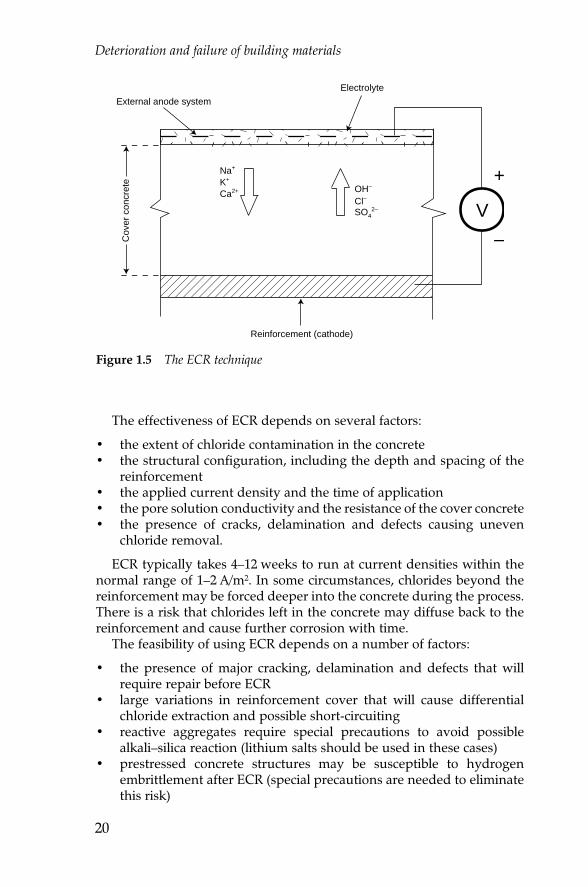
Electrochemical chloride removal. Chloride removal is induced byapplying a direct current between the reinforcement and an electrodethat is placed temporarily onto the outside of the concrete. The impressedcurrent creates an electric field in the concrete that causes negativelycharged ions to migrate from the reinforcement to the external anode.The technique decreases the potential of the reinforcement, increases thehydroxyl ion concentration and decreases the chloride concentrationaround the steel, thereby restoring passivating conditions. Figure 1.5shows the basic principles of electrochemical chloride removal (ECR).
Mildly corrosive,low chlorides orcarbonation
Dense concretewith good coverdepths (>50 mm)
Limited corrosionwith minorpitting of steel
Good
Moderate levelsof chloride atrebar (i.e. <1%)
Moderate qualityconcrete, somecracking
Moderatecorrosion withsome pitting
Moderate
High chloridelevels at rebar(i.e. >1%)
Cracked,damagedconcrete, lowcover to rebar
Entrenchedcorrosion withdeep pitting
Poor
Table 1.12 Likely performance of migrating corrosion inhibitors in concrete
Corrosiveconditions
Concreteconditions
Severity ofcorrosion
Likely inhibition
Chapter 1.qxd 18/10/2002 15:44 Page 19
Deterioration and failure of building materials
20
The effectiveness of ECR depends on several factors:
• the extent of chloride contamination in the concrete• the structural configuration, including the depth and spacing of the
reinforcement• the applied current density and the time of application• the pore solution conductivity and the resistance of the cover concrete• the presence of cracks, delamination and defects causing uneven
chloride removal.
ECR typically takes 4–12 weeks to run at current densities within thenormal range of 1–2 A/m2. In some circumstances, chlorides beyond thereinforcement may be forced deeper into the concrete during the process.There is a risk that chlorides left in the concrete may diffuse back to thereinforcement and cause further corrosion with time.
The feasibility of using ECR depends on a number of factors:
• the presence of major cracking, delamination and defects that willrequire repair before ECR
• large variations in reinforcement cover that will cause differentialchloride extraction and possible short-circuiting
• reactive aggregates require special precautions to avoid possiblealkali–silica reaction (lithium salts should be used in these cases)
• prestressed concrete structures may be susceptible to hydrogenembrittlement after ECR (special precautions are needed to eliminatethis risk)
Figure 1.5 The ECR technique
Electrolyte
V
+
–
External anode system
Cov
er c
oncr
ete
Reinforcement (cathode)
Na+
K+
Ca2+ OH–
Cl–
SO42–
Chapter 1.qxd 18/10/2002 15:44 Page 20

Deterioration of concrete
21
• temporary power supplies of significant capacity are required duringthe application of ECR.
Cathodic protection systemsCathodic protection (CP) systems have an excellent track record in thecorrosion control of steel and reinforced concrete structures. In sacrificialanode systems the anode consists of metals higher than steel in theelectrochemical series (e.g. zinc). The external anode corrodes preferen-tially to the steel and supplies electrons to the cathodic steel surface.
Impressed current CP systems use an external electrical power source tosupply electrons from the anode to the cathode. The anode is placed nearthe surface and is connected to the reinforcement through a transformerrectifier that supplies the impressed current (Figure 1.6). Anodes may beconductive overlays, titanium mesh within a sprayed concrete overlay,discrete anodes or conductive paint systems.
CP repair of concrete structures requires a thorough corrosion surveyby a specialist and the design needs to be undertaken by a corrosionexpert. Reliable CP systems are fully controlled and monitored by a seriesof embedded sensors in order to ensure optimum performance. This isessential since under- or overprotection of the reinforcement may bepotentially harmful to the structure or the CP system. Continuousmonitoring of CP systems is usually done remotely by modem and thepower consumption during operation is extremely small.
V
+–
Rectifier
External anode
Overlay material
Monitor
Embedded reference electrode
Reinforcement
Figure 1.6 A typical cathode protection system
Chapter 1.qxd 18/10/2002 15:44 Page 21

Deterioration and failure of building materials
22
Demolition or reconstructionThis option should only be considered as a last resort since the total cost(capital costs plus loss of service and temporary works) is usually well inexcess of repairs costs. Engineers who have limited repair experience orlack confidence in new repair systems often prefer demolition andreconstruction. It is crucial nevertheless that lessons are learnt from theold structure when designing the replacement.
Alkali–aggregate reaction
Alkaline pore solutions in the concrete react in moist conditions withcertain types of aggregate to form an expansive gel, resulting in the internaldisruption of the concrete. The reaction is slow and its effects only becomenoticeable after several years of service. Depending on the severity of theattack, the consequences of alkali–aggregate reaction (AAR) are:
• degradation of appearance• deterioration in strength• decrease in durability.
Types of alkali–aggregate reaction
Alkali–silica reactionAlkali–silica reaction (ASR) is the most common form of AAR. Alkalinepore solutions react with metastable or highly disordered silica phases(opal, cristobalite, trydimite, volcanic glass, as well as highly strained,microcrystalline or cryptocrystalline quartz) found in particular silicateaggregates (quartzite, greywacke, argillite, hornfels, phyllite, granite,granite-gneiss, granodiorite, etc.) to form a reactive gel that expandswhen it imbibes water. When the swell pressure exceeds the tensilestrength of the concrete (about 4 MPa) the concrete disrupts internally.
Alkali–carbonate rock reactionAlkali–carbonate rock reaction (ACR) is seldom found. The alkaline poresolutions react with certain carbonate rocks (argillaceous dolomiticlimestone), but no expansive gel is formed. The expansion is believed tobe the result of dedolomitisation (reaction between alkali hydroxides anddolomite crystals) and additional swelling of clay minerals in thelimestone made possible by the increased permeability of the rock.
Recognition of alkali–aggregate reaction
It should always be borne in mind that some indicators of AAR may be theresult of other mechanisms, operating either in conjunction or on theirown. Detailed analysis of the structure is thus imperative.
Chapter 1.qxd 18/10/2002 15:44 Page 22

Deterioration of concrete
23
Cracking of concreteThe main and most obvious indicator of AAR is cracking of the concrete.The cracks become just noticeable after about 5 years, but may developwith time to fissures more than 1 mm wide. Where mass concrete isrelatively free to expand in all directions, map or pattern crackingdevelops, but restraint in any direction will influence this crack pattern.
In reinforced concrete the cracking tends to follow the orientation ofthe main reinforcement and maximum stress directions. If the cracksextend to the reinforcement, the steel will start to corrode because theprotective effect of the cover concrete has been nullified. Rust stains willstart to appear from the cracks, suggesting that corrosion of the reinforce-ment is the cause of the crack formation. However, in this case theappearance of rust stains is the result, not the cause, of crack formation.
Expansion of concrete membersExpansion of the concrete results in the closure of movement joints.Warping and offsetting of structural members could also develop.
Presence of gelIn severe cases, streaks and drops of gel with a resinous, jelly-likeappearance (sometimes stained) develop on vertical surfaces. Beware ofconfusion with carbonated lime efflorescence. If the area is treated with asolution of uranium acetate the ASR gel will be fluorescent under UVlight. This is a specialist test and the results must be interpreted withcaution.
DiscolorationAreas with a well-developed crack pattern may appear dark, giving theimpression of permanent dampness. In severe cases, actual dampnesscould develop on the surface.
Confirmation of alkali–aggregate reaction
Suspected cases require full macroscopic and microscopic examination ofcore samples, not loose fragments taken from the surface. The cores mustbe at least 100 mm in diameter and 100 mm long. The exact position ofsampling point, direction of drilling, location and condition of thereinforcement must be recorded. The crack pattern in the immediatevicinity of the coring location must be noted.
Various features are revealed by macroscopic investigation of coressliced longitudinally:
• dark staining along cracks through aggregate, generally parallel withthe surface of the concrete mass
Chapter 1.qxd 18/10/2002 15:44 Page 23

Deterioration and failure of building materials
24
• a white deposit on fracture surfaces of the aggregate, concentratedaround the periphery and 0.3–1 mm thick, giving the impression of areaction rim
• voids in the concrete and cracks in the aggregate or paste are lined orcompletely filled with a reaction product, which is translucent orporcelaineous, hard or soft.
Positive confirmation should be based on thin section petrographicmicroscopy, x-ray diffraction (XRD) analysis of the reaction product andscanning electron microscopy (SEM) investigation with energy-dispersiveanalysis.
Conditions necessary for alkali–aggregate reaction
High alkalinity of pore solutionThe main contributor to the alkalinity of the pore solution is soluble alkaliin the clinker component of the Portland cement. Minor sources arealkalis derived from reactions between the lime formed during hydrationof Portland cement and alkali-containing minerals in the aggregate, aswell as external sources such as salts in aggregates, mixing water, certainadmixtures and seawater spray. The minimum alkali content in theconcrete that is required for ASR to develop varies between about 2 and4 kg/m3, depending on the aggregate type.
Reactive phases in the aggregateThere is a large variation in the reactivity, not only between differenttypes of aggregate materials, but also within a particular type of rock. Thereactivity is determined from service records or laboratory tests for eachsource of aggregate.
Environmental conditionsThe reaction rate roughly doubles with each 10°C increase in meanannual ambient temperature. ASR requires an internal relative humidityof more than about 75%. Climatic fluctuations increase the reaction rate.
Preventive measures
• Use only non-reactive aggregates (not always available).• Use only low alkali cements (the only available cements may be high
in alkalis).• Use appropriate extenders (experimentation is needed to optimise
effectiveness).• Prevent continued wetting of the concrete (often unfeasible in
practice).
Chapter 1.qxd 18/10/2002 15:44 Page 24

Deterioration of concrete
25
Remedial action
• Ascertain whether expansion has stopped.• Monitor growth in crack widths.• Monitor expansion and deflection of structural elements.• Determine the potential future expansion by accelerated expansion
tests.
Reaction dormant• Fill cracks with suitable grout or filler.• Aesthetic considerations may prescribe coating of repaired surfaces.
Reaction activeImmediate crack repair will serve no purpose. Continued expansion mustfirst be prevented by curtailing the reaction. Two approaches areavailable.
• Treat the affected parts of the structure with silane or siloxane toinhibit the ingress of water. Such treatment allows the concrete to dryout over time, thus stopping the reaction, provided that the ambientrelative humidity is below about 75%. (See also: Concrete, Repairstrategies, p. 14)
• Replace the alkali by lithium to eliminate the ASR. A lithium-basedimpregnation treatment is presently under trial.
Important
• If the durability of the concrete is affected to such a degree thatthere is concern for reinforcing steel corrosion, the structureshould first be treated for corrosion, such as with a migratingcorrosion inhibitor. (See also: Concrete, Repair strategies, p. 14)
• Where possible, the structure should be isolated from free wateror wet soil by effective barrier systems. If appropriate, installventilated cladding to protect the structure from rain.
Chemical attack on concrete
Concrete is vulnerable to attack by naturally occurring solutions or variousindustrial wastes (effluent, sugars, lactic acid, etc.). All liquids with a pHbelow 12.5 will attack concrete, but the attack will be slow if the pH is
Chapter 1.qxd 18/10/2002 15:44 Page 25

Deterioration and failure of building materials
26
above about 6, and increases rapidly with increasing acidic conditions. Therate of reaction depends on the temperature, flow rates, solubility of thereaction products, mobility of the ions and permeability of the concrete.Disruption of the concrete is classified as either leaching or spallingdamage, caused by surface or internal deterioration mechanisms.
Soft water
Attack mechanismSoftwater attack is mainly a problem associated with large civilengineering structures, such as irrigation schemes. However, watersupply conduits made from fibre–cement composites may fail as a resultof softwater attack.
Softwater attack can be seen in watercourses where the aggregate ofcanal concrete is slowly exposed in the water flow region. When thereaction extends through the canal lining, major leakage paths form thatmay wash away backfill material and cause the collapse of the structure.
Soft water is defined as water deficient in dissolved calcium andmagnesium ions. Some soft water (also termed ‘pure water ’)contains aggressive carbon dioxide or organic acids such as humicacids in solution, reducing the pH to below 5.0 and thus making thewater highly aggressive.
Remedial action• There are no remedial actions to halt or reverse the action of soft
water.• Pure or slightly acidic domestic water supplies should be stabilised to
avoid the cement being dissolved.• It is not possible to make acid-proof cement products using Portland
cement. Attempts to buffer the action by using dolomite as anaggregate will not be effective, because the aggressive waters willattack all alkaline material. The reactions will continue until all thecement paste has been dissolved.
Sulphates
Attack mechanismA major cause of deterioration of concrete is when sulphate solutionsreact with certain constituents in set concrete and the process isaccompanied by a volume increase. Reactions of this kind are when
Chapter 1.qxd 18/10/2002 15:44 Page 26

Deterioration of concrete
27
concrete is exposed to sulphates. It is important to note that thesereactions require high moisture levels.
Three reactions involving sulphates may take place:
• Reaction of sodium sulphate with free calcium hydroxide in setconcrete to form calcium sulphate (gypsum). The crystallisationof the reaction product results in expansion and disruption ofthe concrete.
• Reaction of calcium and sodium sulphates with hydratedcalcium aluminates and ferrites to form calcium sulpho-aluminate (ettringite) and sulphoferrite hydrates. The reactionresults in a doubling of the volume of the components, causingdisruption of the concrete.
• The presence of magnesium sulphates results in thedecomposition of hydrated calcium silicates, which results in adecrease in the strength of the concrete.
The sources of sulphates are:
• sulphate minerals (mainly gypsum) in the surrounding soil• brackish groundwater and surface water• sulphate-bearing solutions, such as domestic and industrial effluent.
Remedial action• There are no remedial actions to reverse the disintegration of concrete
caused by the disruptive action of sulphate attack.• Sulphate attack will be curtailed if the continuous wetting of the
concrete is prevented.• Resistance of concrete products to attack by sulphates may be
improved at the manufacturing stage by:– Autoclaving (6 hours at 850 kPa, 175°C). This is only practical in
the case of certain precast units.– Using sulphate-resistant Portland cement. Rapid cooling of
clinker minimises the formation of C3A precipitation.– Incorporating fly ash and ground granulated blast furnace slag
(GGBS) of appropriate quality and appropriate level into themix.
See also:Masonry, Sulphate attack, p. 59
Chapter 1.qxd 18/10/2002 15:44 Page 27

Deterioration and failure of building materials
28
Fire damage
Effect of high temperatures
High temperatures break down hydraulic cementitious compounds. Thestrength of concrete is not severely affected by temperatures below 250°C,but drops to 80% at about 450°C and to 50% at about 650°C. On coolingthere is a further loss in strength. Note that fire temperatures in enclosedspaces can exceed 1500°C.
Concrete exposed to fires is prone to spalling because the low thermalconductivity results in steep temperature gradients. High moisturecontents in the concrete also cause high pore pressures from trappedsteam that exacerbate the risk of spalling. Surface damage starts withslight crazing and progresses to widespread scaling, cracking andextensive spalling. However, because of the low thermal conductivity ofconcrete, damage is usually confined to the outer 50 mm or so, leaving theunderlying concrete in a sound condition, largely unaffected by the fire.
Fire-affected concrete has a lumpy, powdery appearance. The colour offire-exposed concrete provides some indication of the maximumexposure temperature (Table 1.13).
Remedial action
• Remove all fire-damaged material; treat any exposed reinforcementand patch with repair mortar or micro-concrete.
• It is very important to realise that the repaired surface is not loadbearing. It is thus vital to establish whether the structural membersstill have adequate load-bearing capacity after removing all fire-damaged material.
See also:Concrete, Repair strategies, p. 14
Frost attack
Damage mechanism
Dry concrete (i.e. concrete with a low level of water in the interconnectedpores) is resistant to frost action. The gel pores in hydrated Portlandcement are so small that the water in them will not freeze. The freezingpoint of the water in the capillaries depends on the salt content, but it iswell below 0°C.
When the water in the interconnected pores of wet concrete freezes,there is a 12% increase in volume. If these pores are saturated above acritical value (about 80–90%, depending on the properties of the concrete)frost action could disrupt the concrete. The damage caused by cycles of
Chapter 1.qxd 18/10/2002 15:44 Page 28

Deterioration of concrete
29
freezing and thawing is cumulative and leads to flaking of the surfacelayers or even total crumbling of the material.
The mechanisms causing disintegration of porous materials by frostaction are quite complex. Pore structure and size distribution have a verydecisive influence on the process.
Remedial action
• Unless the concrete is of poor quality and very porous, frost damageis unsightly, rather than damaging.
• In conditions where cycles of freezing and thawing are common,quality concrete (low permeability) should be used and compactedwell during placing.
• Saturation of the concrete during thawing periods should beprevented.
• Air-entrained concrete could have good frost resistance, because thesmall voids formed by the air bubbles act as a pressure-relievingsystem.
See also:Masonry, Frost attack, p. 65Tiling, Frost attack, p. 78
Dimensional change
Stress failure (cracking or crushing) of concrete is not caused by materialfailure, but is the result of bad design or poor workmanship. The effectsof shrinkage, creep and thermal expansion in large reinforced concretestructures must be allowed for in the design stage by incorporatingmovement joints, while good workmanship must ensure that these jointsare effective.
Differential dimensional change in composite building systems(concrete frame structure with infilling of fired clay brickwork, or ceramictiled areas on concrete substrates) contributes to the failure of suchsystems. Ceramic elements (clay bricks and tiles) tend to expandirreversibly with time, as a result of reaction with moisture. Thecombination of shrinkage and creep of concrete and expansion of ceramicelements can cause considerable stresses in a structure. The magnitude of
Table 1.13 Colour of concrete exposed to high temperatures
Temperature (°C)
Colour
250
Pink
300
Pink-red
600
Black-grey
950
Buff
Chapter 1.qxd 18/10/2002 15:44 Page 29
Deterioration and failure of building materials
30
such dimensional changes must be taken into account in the design,position and maintenance of movement joints.
Note that bleeding and the initial plastic shrinkage during the settingstage are not considered in this context.
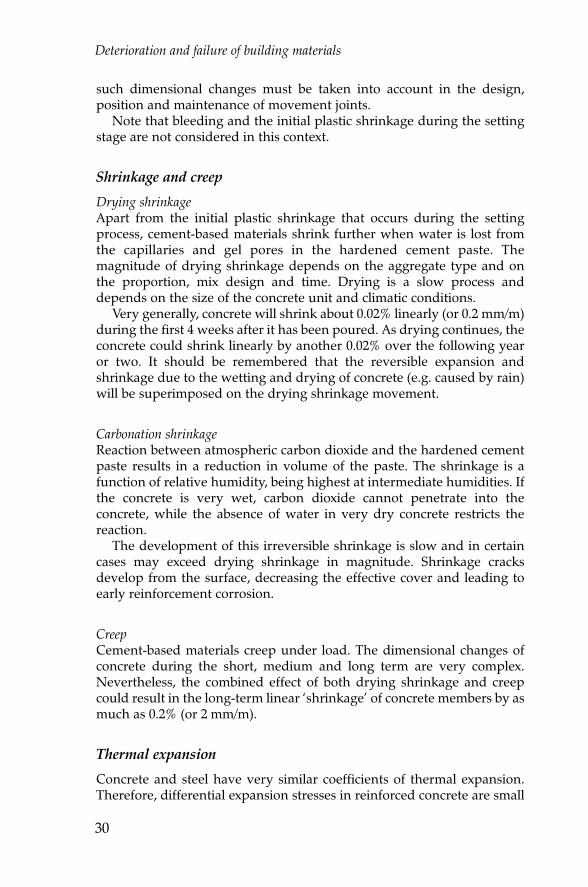
Shrinkage and creep
Drying shrinkageApart from the initial plastic shrinkage that occurs during the settingprocess, cement-based materials shrink further when water is lost fromthe capillaries and gel pores in the hardened cement paste. Themagnitude of drying shrinkage depends on the aggregate type and onthe proportion, mix design and time. Drying is a slow process anddepends on the size of the concrete unit and climatic conditions.
Very generally, concrete will shrink about 0.02% linearly (or 0.2 mm/m)during the first 4 weeks after it has been poured. As drying continues, theconcrete could shrink linearly by another 0.02% over the following yearor two. It should be remembered that the reversible expansion andshrinkage due to the wetting and drying of concrete (e.g. caused by rain)will be superimposed on the drying shrinkage movement.
Carbonation shrinkageReaction between atmospheric carbon dioxide and the hardened cementpaste results in a reduction in volume of the paste. The shrinkage is afunction of relative humidity, being highest at intermediate humidities. Ifthe concrete is very wet, carbon dioxide cannot penetrate into theconcrete, while the absence of water in very dry concrete restricts thereaction.
The development of this irreversible shrinkage is slow and in certaincases may exceed drying shrinkage in magnitude. Shrinkage cracksdevelop from the surface, decreasing the effective cover and leading toearly reinforcement corrosion.
CreepCement-based materials creep under load. The dimensional changes ofconcrete during the short, medium and long term are very complex.Nevertheless, the combined effect of both drying shrinkage and creepcould result in the long-term linear ‘shrinkage’ of concrete members by asmuch as 0.2% (or 2 mm/m).
Thermal expansion
Concrete and steel have very similar coefficients of thermal expansion.Therefore, differential expansion stresses in reinforced concrete are small
Chapter 1.qxd 18/10/2002 15:44 Page 30

Deterioration of concrete
31
and thus cannot cause stress failure. This is not the case with embeddedaluminium fittings.
The thermal expansion of ceramic bricks and tiles is significantlyhigher than that of cement products (Table 1.14). However, the diurnaland seasonal temperature changes in structures are generally notsufficient to result in excessive thermal stressing of the structure.
Remedial action
• Incorporate and maintain effective movement joints in the structure.• For repair of concrete that has suffered stress failure, see Concrete,
Repair strategies, p. 14.
See also:Concrete, Repair strategies, p. 14Masonry, Differential movement, p. 53Tiling, Differential movement, pp. 82, 84
Further reading
Australian Concrete Repair Association. Guide to concrete repair andprotection. Standards Australia, Sydney, 1996.Addis B.J. and Basson J.J. Diagnosing and repairing the surface of reinforcedconcrete damaged by corrosion of reinforcement. Portland Cement Institute,Midrand, 1989.Addis B.J. and Owens G. (eds). Fulton’s concrete technology, 8th edn.Cement & Concrete Institute, Midrand, 2001.American Concrete Institute. Guide to durable concrete. American ConcreteInstitute, Detroit, 1992.American Society for Testing and Materials. ASTM C876 Standard test
Table 1.14 Thermal expansion of building materials
Material Coefficient of thermalexpansion
(per °C × 10-6
)
Expansion(mm/m per 20°C)
Steel
Aluminium
Dense concrete
Fired clay bricks and tiles
Calcium silicate bricks
11–12
22–24
11–13
6–9
8–14
0.22–0.24
0.44–0.48
0.22–0.26
0.12–0.18
0.16–0.28
Chapter 1.qxd 18/10/2002 15:44 Page 31

method for half-cell potentials of uncoated reinforcing steel in concrete.ASTM, Philadelphia, 1991.Broomfield J.P. Corrosion of steel in concrete: appraisal and repair. Chapmanand Hall, London, 1997.Comite Euro-International Du Beton. Durable concrete structures. ThomasTelford, London, 1992, Information Bulletin No. 183.Concrete Society. Diagnosis of deterioration in concrete structures. ConcreteSociety, Crowthorne, 2000, Technical Report 54.Hobbs D.W. Alkali–silica reaction in concrete. Thomas Telford, London, 1988.National standard specifications and code of practices
Entry web sites
International Concrete Repair Institute: http://www.icri.orgPortland Cement Association: http://www.portcement.org
Deterioration and failure of building materials
32
Chapter 1.qxd 18/10/2002 15:44 Page 32