Detection Of Moving Object On Any Terrain By Using … Of Moving Object On Any Terrain By ......
17
International Journal of Scientific & Engineering Research, Volume 5, Issue 5, May-2014 1638 ISSN 2229-5518 IJSER © 2014 http://www.ijser.org Detection Of Moving Object On Any Terrain By Using Image Processing Techniques D. Mohan Ranga Rao, T. Niharika Abstract Detection of moving object in during day light has been an active research areas and variety of well established algorithms have been proposed. However, the detection moving objects during night time has not yet received equal attention as the detection during the day time. There can be two important reasons for this. Firstly, because of the absent of light, the object does not appear to be visible and hence the camera or capturing device used for the day light would not able to capture this object during night time. Secondly, the method proposed during day light does not work during night time since the surrounding situation is different. During night time, moving vehicle for example will have its lights on that will enlighten its surrounding. This bright area will also change as the vehicle moves and as a result this will affect the image differencing operation. To avoid this false moving object, different approach has to be developed. A technique that this project will look at is to consider only dense bright regions that correspond to the vehicle’s lights only. Depending on the angle of the camera, the distance between lights of the car will maintain so as for other vehicles. In addition, different distance value can be used to classify the type of moving vehicle i.e. either it’s a car, lorry, or motorcycle. As such, this project will a software-based project. A video sequence captured from infrared sensitive camera for night vision application will be utilized. 1. Introduction to Motion Detection A video sequence is made of basically a series of still images at a very small interval time between each capture. The use of image sequences to depict motion dates back nearly two centuries. One of the earlier approaches to motion picture “display” was invented in 1834 by the mathematician William George Horner. The impression of motion is illusory. An image is perceived to remain for a period of time after it has been removed from view. This illusion is the basis of all motion picture displays. When an object is moved slowly, the images of the object appear as a disjoint sequence of still images. As the speed of movement increases and the images are displayed at a higher rate, a point is reached at which motion is perceived, even though the images appear to flicker. If the speed of the motion is increased, it will reach a point at which flicker is no longer perceived. The first attempt to acquire a sequence of photographs from an object in motion is reputed to have been inspired by a wager of Leland Stanford circa 1872. The wager involved whether or not, at any time in its gait, a trotting horse has all four feet off the ground. Motion detection done at broad daylight and night has some slight differences. Detection of moving object in during day light has been an active research areas and variety of well established algorithms have been proposed. However, the detection moving objects during night time has not yet received equal attention as the detection during the day time. Moving object detection done at night is a more difficult task as it is done in the absent of light, thus, the object does not appear to be clearly visible. This explains why the camera or capturing device used for the day light would not able to capture this object during night time. Another reason to prove that the method proposed during day light does not work during night time is because the surrounding situation is different. During night time, moving vehicle for example will have its lights on that will enlighten its surrounding. This bright area will also change as the vehicle moves and as a result this will affect the image differencing operation. To avoid this false moving object, different approach has to be developed. A technique that this project will look at is to consider only dense bright regions that correspond to the vehicle’s lights only. Depending on the angle of the camera, the distance between lights of the car will maintain so as for other vehicles. IJSER
Transcript of Detection Of Moving Object On Any Terrain By Using … Of Moving Object On Any Terrain By ......

International Journal of Scientific & Engineering Research, Volume 5, Issue 5, May-2014 1638 ISSN 2229-5518
IJSER © 2014 http://www.ijser.org
Detection Of Moving Object On Any Terrain By Using Image Processing Techniques
D. Mohan Ranga Rao, T. Niharika Abstract
Detection of moving object in during day
light has been an active research areas and variety
of well established algorithms have been proposed.
However, the detection moving objects during night
time has not yet received equal attention as the
detection during the day time. There can be two
important reasons for this. Firstly, because of the
absent of light, the object does not appear to be
visible and hence the camera or capturing device
used for the day light would not able to capture this
object during night time. Secondly, the method
proposed during day light does not work during
night time since the surrounding situation is
different. During night time, moving vehicle for
example will have its lights on that will enlighten its
surrounding. This bright area will also change as
the vehicle moves and as a result this will affect
the image differencing operation. To avoid this
false moving object, different approach has to be
developed. A technique that this project will look at
is to consider only dense bright regions that
correspond to the vehicle’s lights only. Depending
on the angle of the camera, the distance between
lights of the car will maintain so as for other
vehicles. In addition, different distance value can
be used to classify the type of moving vehicle i.e.
either it’s a car, lorry, or motorcycle. As such, this
project will a software-based project. A video
sequence captured from infrared sensitive camera
for night vision application will be utilized.
1. Introduction to Motion Detection
A video sequence is made of basically a
series of still images at a very small interval time
between each capture. The use of image
sequences to depict motion dates back nearly two
centuries. One of the earlier approaches to motion
picture “display” was invented in 1834 by the
mathematician William George Horner.
The impression of motion is illusory. An
image is perceived to remain for a period of time
after it has been removed from view. This illusion
is the basis of all motion picture displays. When
an object is moved slowly, the images of the
object appear as a disjoint sequence of still
images. As the speed of movement increases and
the images are displayed at a higher rate, a point
is reached at which motion is perceived, even
though the images appear to flicker. If the speed
of the motion is increased, it will reach a point at
which flicker is no longer perceived.
The first attempt to acquire a sequence
of photographs from an object in motion is reputed
to have been inspired by a wager of Leland
Stanford circa 1872. The wager involved whether
or not, at any time in its gait, a trotting horse has
all four feet off the ground.
Motion detection done at broad daylight
and night has some slight differences. Detection of
moving object in during day light has been an active
research areas and variety of well established
algorithms have been proposed. However, the
detection moving objects during night time has not
yet received equal attention as the detection during
the day time.
Moving object detection done at night is a
more difficult task as it is done in the absent of light,
thus, the object does not appear to be clearly visible.
This explains why the camera or capturing device
used for the day light would not able to capture this
object during night time. Another reason to prove that
the method proposed during day light does not work
during night time is because the surrounding situation
is different. During night time, moving vehicle for
example will have its lights on that will enlighten its
surrounding. This bright area will also change as the
vehicle moves and as a result this will affect the
image differencing operation. To avoid this false
moving object, different approach has to be
developed.
A technique that this project will look at is
to consider only dense bright regions that correspond
to the vehicle’s lights only. Depending on the angle of
the camera, the distance between lights of the car
will maintain so as for other vehicles.
IJSER

International Journal of Scientific & Engineering Research, Volume 5, Issue 5, May-2014 1639 ISSN 2229-5518
IJSER © 2014 http://www.ijser.org
1.2 Limitation of Motion Detection at Night
Motion detection is used extensively at night
especially in the surveillance system. Motion detection
done at night scene poses a few challenges in
obtaining good or acceptable image quality due to a
few reasons:
• Low Light scenario
The scene or surrounding environment is not
well lighted. In order to obtain a good and accurate
image, the brightness level must be high enough to
capture almost every single detail within the viewing
scope of the camera. In a low-light situation, this is not
possible because the brightness level is not sufficient
to capture every single detail. A lot of detail information
is lost due to low-light. In order to compensate that and
at the same time to maintain the a decent image
quality, some techniques are used to pre and post
process the image.
• Noisy IR camera
IR camera has a relatively high noise level.
IR camera works very well in the night scene because
the image is captured based on the infra-red range in
the light transmitted into the camera.
• Poor distinction between the object and the
background
Since the scene is not well lighted, this
makes the threshold value between the
background and the object, small. Thus, it is
harder to differentiate the background and the
object due to the small threshold differences.
1.3 Objective
The objective of this project is to develop
an algorithm for the purpose of detecting motion
(specifically moving vehicle) from a video
sequence captured by an infra-red sensitive
camera.
A suitable technique of image processing
is to be implemented for the purpose of detecting
motion that exists in the video sequence.
Secondary technique that is to be implemented is
the filtering and thresholding process that is needed
to improve the image to be less noisy, thus
improving the image quality. Motion detection
technique is chosen properly to suit the image
captured at night scene whereby the light source is
scarce.
In addition, different distance value can
be used to classify the type of moving vehicle i.e.
either it’s a car, lorry, or motorcycle. As such, this
project will be a software based project. A video
sequence captured from infrared sensitive
camera for night vision application will be utilized.
1.4 Project Scope
This scope of the project is mainly to focus
on the development of a software module that will do
the image processing. The algorithm will be intelligent
enough to filter out any noise that might exist in the IR
sensitive video sequence. Besides that, this algorithm
is designed to detect moving objects (specifically
vehicles) at night, with the condition that the vehicle
must turn on the headlights.
The scope of this project does not include object
tracking and classification.
2. Digital Image Processing
Image processing is any form of information
processing for which the input is an image, such as
photographs or frames of video; the output is not
necessarily an image, but can be for instance a set
of features of the image. Most image-processing
techniques involve treating the image as a two-
dimensional signal and applying standard signal-
processing techniques to it.
Digital image processing is the use of
computer algorithms to perform image processing on
digital images. Digital image processing has the
same advantages over analog image processing as
digital signal processing has over analog signal
processing — it allows a much wider range of
algorithms to be applied to the input data, and can
avoid problems such as the build-up of noise and
signal distortion during processing. Other problems
which might arise are geometric transformations
such as enlargement, reduction, and rotation; color
corrections such as brightness and contrast
IJSER
International Journal of Scientific & Engineering Research, Volume 5, Issue 5, May-2014 1640 ISSN 2229-5518
IJSER © 2014 http://www.ijser.org
adjustments, quantization, or conversion to a
different color space, registration (or alignment) of
two or more images; combination of two or more
images, e.g. into an average, blend, difference, or
image composite; interpolation, demosaicing, and
recovery of a full image from a RAW image format
like a Bayer filter pattern; segmentation of the image
into regions; image editing and digital retouching;
and extension of dynamic range by combining
differently exposed images.
2.1 Filtering
Filtering is an important feature in image
processing. Most of the image enhancement work in
digital image processing is based on filtering. Image
filtering is used for noise removal, contrast sharpening
and contour highlighting. Image contrast and brightness
can be tuned using filters.
There are a few types of space invariant
filters which uses a moving window operator. The
operator usually affects one pixel of the image at a
time, changing its value by some function of a local
region of pixels. The operator moves over the image to
affect all the pixels in the image. Some of the examples
of these filters are:
• Neighborhood-averaging filters
These replace the value of each pixel, a[i,j]
say, by a weighted-average of the pixels in some
neighborhood around it, i.e. a weighted sum of
a[i+p,j+q], with p = -k to k, q = -k to k for some
positive k; the weights are non-negative with the
highest weight on the p = q = 0 term. If all the
weights are equal then this is a mean filter.
• Median filters
This replaces each pixel value by the median
of its neighbors, i.e. the value such that 50% of the
values in the neighborhood are above, and 50% are
below. This can be difficult and costly to implement due
to the need for sorting of the values. However, this
method is generally very good at preserving edges.
• Mode filters
Each pixel value is replaced by its most
common neighbor. This is a particularly useful filter
for classification procedures where each pixel
corresponds to an object which must be placed into
a class; in remote sensing, for example, each class
could be some type of terrain, crop type, water and
etc. A non-space invariant filtering, using the above
filters, can be obtained by changing the type of filter
or the weightings used for the pixels for different
parts of the image.
2.2 Grayscaling
In computing, a grayscale or greyscale digital
image is an image in which the value of each pixel is a
single sample. Displayed images of this sort are
typically composed of shades of gray, varying from
black at the weakest intensity to white at the strongest,
though in principle the samples could be displayed as
shades of any color, or even coded with various colors
for different intensities. Grayscale images are distinct
from black-and-white images, which in the context of
computer imaging are images with only two colors,
black and white; grayscale images have many shades
of gray in between. In most contexts other than digital
imaging, however, the term "black and white" is used in
place of "grayscale"; for example, photography in
shades of gray is typically called "black-and-white
photography". The term monochromatic in some digital
imaging contexts is synonymous with grayscale, and in
some contexts synonymous with black-and-white.
Grayscale images are often the result of
measuring the intensity of light at each pixel in a single
band of the electromagnetic spectrum (e.g. visible
light). Grayscale images intended for visual display are
typically stored with 8 bits per sampled pixel, which
allows 256 intensities (i.e., shades of gray) to be
recorded, typically on a non- linear scale. The accuracy
provided by this format is barely sufficient to avoid
visible banding artifacts, but very convenient for
programming. Medical imaging or remote sensing
applications, which often require more levels, to make
full use of the sensor accuracy (typically 10 or 12 bits
per sample) and to guard against round off errors in
computations. Sixteen bits per sample (65536 levels)
appears to be a popular choice for such uses
To convert any color to its most
approximate level of gray, the values of its red, green
and blue (RGB) primaries must be obtained. There
are several formulas that can be used to do the
conversion. One of the accurate conversion model is
the luminance model, which takes the average of all
three color components. It is sufficient to add the
30% of the red value plus the 59% of that of the
IJSER
International Journal of Scientific & Engineering Research, Volume 5, Issue 5, May-2014 1641 ISSN 2229-5518
IJSER © 2014 http://www.ijser.org
green plus the 11% of that of the blue, no matter
whatever scale is employed (0.0 to 1.0, 0 to 255,0%
to 100%, etc.) The resultant level is the desired gray
value.
These percentages are chosen due to the
different relative sensibility of the normal human eye
to every of the primary colors (higher to the green,
lower to the blue)
2.3 Thresholding
Thresholding is the simplest method of
image segmentation. Individual pixels in a grayscale
image are marked as 'object' pixels if their value is
greater than some threshold value (assuming an
object to be brighter than the background) and as
'background' pixels otherwise. Typically, an object
pixel is given a value of '1' while a background pixel
is given a value of '0'.
The key parameter in thresholding is
obviously the choice of the threshold. Several
different methods for choosing a threshold exist.
The simplest method would be to choose the mean
or median value, the rationale being that if the
object pixels are brighter than the background, they
should also be brighter than the average. In a
noiseless image with uniform background and object
values, the mean or median will work beautifully as
the threshold, however generally speaking; this will
not be the case. A more sophisticated approach
might be to create a histogram of the image pixel
intensities and use the valley point as the threshold.
The histogram approach assumes that there is
some average value for the background and object
pixels, but that the actual pixel values have some
variation around these average values. However,
computationally this is not as simple as it seems,
and many image histograms do not have clearly
defined valley points. Ideally we're looking for a
method for choosing the threshold which is simple,
does not require too much prior knowledge of the
image, and works well for noisy images.
A good such approach is an iterative method, as
follows:
1. An initial threshold (T) is chosen, this can be
done randomly or according to any other method
desired.
2. The image is segmented into object and
background pixels as described above, creating two
sets:
1. G1 = {f(m,n):f(m,n)>T} (object pixels)
2. G2 = {f(m,n):f(m,n) T} (background
pixels) (note, f(m,n) is the value of the pixel
located in the mth column, nth row)
3. The average of each set is computed.
1. m1 = average value of G1
2. m2 = average value of G2
4. A new threshold is created that is the average of
m1 and m2
1. T' = (m1 + m2)/2
5. Go back to step two, now using the new
threshold computed in step 4, keep repeating until
the new threshold matches the one before it (i.e.
until convergence has been reached).
Another approach is to calculate the new
threshold in step 4 using the weighted average of
m1 and m2: T' = (||G1||*m1 +
||G2||*m2)/(||G1||+||G2||), where ||Gn|| is the number
of pixels in Gn. This approach often gives a more
accurate result.
This iterative algorithm is a special one-
dimensional case of the k-means clustering algorithm,
which has been proven to converge at a local minimum
- meaning that a different initial threshold may result in
a different parts of the image.
The operating block diagram of this
algorithm is shown in Figure 3.1. The overall
algorithm consists of a few blocks, starting from the
acquisition of the image till the end result. Figure 3.1
shows the sequence of the processing starting form
the frame grabber until to the final detection output.
IJSER

International Journal of Scientific & Engineering Research, Volume 5, Issue 5, May-2014 1642 ISSN 2229-5518
IJSER © 2014 http://www.ijser.org
2.4 Frame Grabber
Firstly, the video sequence is acquired from
the infra-red camera. The video sequence is then being
sampled into multiple frames. The more frames that
have been sampled or grabbed, the better it is as this
will increase the sensitivity and accuracy of the system.
This enable detection for any slight movement that
might occurs in the video sequence. The tradeoff for a
large number of frames grabbed is the memory,
bandwidth and frame processing. The more frames
grabbed means there are more frames to process and
needs more computation time. With the increased
frames, a sufficiently large storage is needed which
lead to higher might cost. However, number of frames
grabbed must be large enough to produce decent and
accurate computation, and at the same time does not
cost too much on the memory and other resources.
For this project, the computation is not a
limitation as the resolution of the video sequence
is not very high and since the video is captured in
low light scene, therefore, the colour information
is relatively lower than a daylight image. This
project can afford to sample in a smaller sample
time and computation of many frames is not a
major concern.
2.5 Grayscaling
Once the frames are grabbed, each frame
has to go through the same chain of processing. The
first process is gray scaling. In computing, a
grayscale digital image is an image in which the value
of each pixel is a single sample. Displayed images of
this sort are typically composed of shades of gray,
varying from black at the weakest intensity to white at
the strongest, though in principle the samples could
be displayed as shades of any color, or even coded
with various colors for different intensities. Grayscale
images are distinct from black-and-white images,
which in the context of computer imaging are images
with only two colors, black and white; grayscale
images have many shades of gray in between. In
most contexts other than digital imaging, however,
the term "black and white" is used in place of
"grayscale"; for example, photography in shades of
gray is typically called "black-and-white photography".
The term monochromatic in some digital imaging
contexts is synonymous with grayscale, and in some
contexts synonymous with black-and-
white.zGrayscale images are often the result of
measuring the intensity of light at each pixel in a
single band of the electromagnetic spectrum (e.g.
visible light). Grayscale images intended for visual
display are typically stored with 8 bits per sampled
pixel, which allows 256 intensities (i.e., shades of
gray) to be recorded, typically on a non-linear scale.
Gray scaling is necessary to remove
the colour values of the image and converts the
image/frame into a grayscale image, which
simplifies computation drastically, compared to a
colour RGB image. However, for an image
captured at night whereby the scene is mostly
lowlight, the colour image actually looks like a
grayscale image from the human naked eyes.
There are several algorithms which can be
used to convert color image to grayscale. Either the
luminance model or the mathematical averaging
luminance model can be used. In this project, the
luminance model is chosen because it gives a better
gray scaling result. Colour’s in an image may be
converted to a shade of gray by calculating the
effective brightness or luminance of the colour and
using this value to create a shade of gray that
matches the desired brightness.
The luminance model is given as,
Y=0.299R + 0.587G + 0.114B
where all the pixel values are changed to that of the
IJSER
International Journal of Scientific & Engineering Research, Volume 5, Issue 5, May-2014 1643 ISSN 2229-5518
IJSER © 2014 http://www.ijser.org
luminance model result (Y).
2.6 Noise Filtering
In signal processing or computing noise
can be considered as data without meaning or
unwanted information. In other words, noise is
data that is not being used, but is simply
produced as an unwanted by-product of other
activities. This noise will corrupt or distort the true
measurement of the signal, such that any
resulting data is a combination of signal and
noise. Additive noise, probably the most common
type, can be expressed as:
I(t) = S(t) +
N(t)
where I(t) is the resulting data
measured at time t, S(t) is the original signal
measured, and N(t) is the noise introduced by the
sampling process, environment and other sources
of interference.
A wide variety of filtering algorithms have
been developed to detect and remove noise,
leaving as much as possible of the pure signal.
These include both temporal fillters, and spatial
filters. The presence of the filter is to obtain an
ideally noise-free image at the output.
In this project, an averaging filter is used.
The optimum filter for improving the signal-to-noise
ratio in a commonly encountered signal recovery
situation is the ideal averaging filter. After
grayscaling, the image has to undergo the filtering
process. Noise filtering is carried out to filter out any
noise in the captured image or any noise picked up
from the infra-red camera.
An averaging filter with a kernel of 1/9
{1,1,1; 1,1,1; 1,1,1} would suffice. Averaging filter is
useful in reducing random noise while retaining a
sharp step response. This makes it the premier filter
for time domain encoded signals. However, the
average is the worst filter for frequency domain
encoded signals, with little ability to separate one
band of frequencies from another.
2.7 Background Subtraction
The next block would be the background
subtraction technique. Background subtraction
identifies moving objects from the portion of a video
frame that differs significantly from a background
model. There are many challenges in developing a
good background subtraction algorithm. There are a
few criteria in determining how good the background
subtraction algorithm is. The first criterion is
robustness. The algorithm must be robust against
changes in illumination, ideally. Second, it should
avoid detecting non-stationary background objects
such as moving leaves, rain, snow, and shadows
cast by moving objects. Finally, its internal
background model should react quickly to change in
background such as starting and stopping of
vehicles.
Simple background subtraction techniques
such as frame differencing and adaptive median
filtering can be implemented. The trade-off of
implementing this simple technique is the accuracy
of the end result. Complicated techniques like the
probabilistic modeling techniques often produce
superior performance. The set back of complicated
and sophisticated method is the level of complexity
in terms of computation. The hardware
implementation of a highly complex computation
might cost more than what a simple technique
implementation cost. Besides, pre-and post-
processing of the video might be necessary to
improve the detection of moving objects. Spatial and
temporal smoothing might be able to remove the
raindrops (in rainy weather condition), so that the
rain drop is not detected as the targeted moving
object.
The rate and weight of model updates
greatly affect foreground results. Slow adapting
background models cannot quickly overcome large
changes in the image background. This causes in a
period of time where many background pixels being
incorrectly classified as foreground pixels. A slow
update rate also tends to create a ghost mask which
trails the actual object. Fast adapting background
models can quickly deal with background changes,
but they fail at low frame rates. They are also very
susceptible to noise and the aperture problem. These
observations indicate that a hybrid approach might
help mitigate the drawbacks of each.
Formula for background subtraction is:
Bt = (1-α)Bt-1 + αIt
IJSER
International Journal of Scientific & Engineering Research, Volume 5, Issue 5, May-2014 1644 ISSN 2229-5518
IJSER © 2014 http://www.ijser.org
D = |It – Bt-1| (absolute)
where Bt is estimated background, It is image
at time equals to t. α is the weight which ranges
from 0 to 1.
The problem that arises is the
possibility of some very bright spots that are
produced from the reflection of the headlights.
These reflections can be due to intense light
reflection from other cars which are parked
surrounding the area or it can be due to other
object which is a good source of light reflection.
Only reflection from the headlights will cause
this problem. The regular static lamp post by
the road side does not contribute to this
problem. Some of these lights are not filtered
by the algorithm, especially those which are
quite big in area. This problem is significantly
visible after the thresholding process.
2.8 Thresholding
Thresholding is useful to separate
out the regions of the image corresponding to
objects of interest, from the background.
Thresholding often provides an easy and
convenient way to perform segmentation on
the basis of the different intensities in the
foreground and background regions of an
image. The output of the thresholding
operation is a binary image which, one state
will indicate the foreground objects while the
complementary state will correspond to the
background. With the right threshold value
identified and set, the system is able to
produce an image which highlights area where
the predicted movement is, with reference to
the background. However, thresholding might
also produce some false pixels which values
are near the threshold values and this might be
detected at moving object as well. One set
back of the thresholding process is that it is
very susceptible to the variation of luminance,
which might affect the robustness and reliability
of the algorithm. For this project, thresholding
is a compulsory process where the headlights
of the car are clearly enhanced. Before
thresholding, the image is still in grey level and
the headlights contrast is not clearly visible.
After thresholding, the image now is in black
and white. The headlight areas are now white
and the background is now black. This sets a
very obvious contrast between the headlight
which is the area of interest, and the rest of the
background. This is necessary for further
detection process.
3.Detection Mechanism
Final processing block is where the real detection takes
place. This part of the processing is responsible to
identify the moving vehicle from the static objects or the
background, by only detecting the moving headlights. It
is impossible to detect the body of the vehicle as the
targeted object, as this is done at a low light scene.
Unlike the daytime image processing,
the body of the vehicle is not highly visible and
contrast to the background at night scene. In order
to detect the moving object just like the daytime
detection would do, the headlight of the vehicle is
the key factor in night detection. At night scene,
vehicles normally would turn on the headlight and
this project focuses on detecting the headlight of
this vehicle. However, the light beam of the
headlights should not be detected as the moving
object. This problem has been taken care of in
background subtraction technique, where the light
beam and moving shadow is being taken care off.
At this point, the image (which has
undergone the previous processing) shows a very
high contrast of the moving object to point out the
area where the movement occurs. However, due
to some imperfection and illumination variance
that might occur, some of the single or smaller
clusters of pixels (at random) are detected as
moving objects, when in actual fact, these pixels
are not moving object.
These smaller clusters of pixels can be the
reflection of the moving vehicle headlight onto the
neighboring static vehicle’s side mirror. Sometimes,
these can also be the reflection of the backlight from
the white lines on the road. When these false
reflection is detected as ‘moving objects’, the
algorithm in this block must be able to distinguish and
ignore these false objects.
In short, this stage of the processing
IJSER

International Journal of Scientific & Engineering Research, Volume 5, Issue 5, May-2014 1645 ISSN 2229-5518
IJSER © 2014 http://www.ijser.org
removes all these unwanted clusters of pixels. The
leftover or remaining clusters are the ones which
are needed for further processing.
Next, the detection algorithm move
forward to filter off the brake lights that might be
present in the vehicles which are moving
horizontally moving from left to right or vice versa.
The presence of the brake lights does not help in
the detection of the moving vehicle. The brake
lights are filtered out by detecting a defined
horizontal axis, whereby the locations of the axis in
pixels are correlated to the scale of the scene. The
lights or object and above the axis are detected as
brake lights, thus will be filtered out.
The directions of the lights movement are
detected in the subsequent processing. With the
two video sequences provided, the vehicles can be
moving from the horizontal left to right direction or
vertically bottom to top direction. Four adjacent
frames are computed right from the beginning,
which is starting from the grayscale conversion. At
the background subtraction block, two output
images are obtained from the four frames
computation. The first two frames output an image
while the third and fourth frames output another
output image. These two output images are
compared. The comparison will be able to tell if the
vehicle is moving in the horizontal direction or the
vertical direction.
If the vehicle is moving in the horizontal
position, the headlight and the backlight will be
detected and regarded as belonging to the same
vehicle. The length of the car is the criteria used to
distinguish the front headlight and the backlight.
When this criterion is fulfilled, the boundary will be
drawn surrounding these lights.
If the vehicle is moving in the vertical
position, the criteria to draw the boundary are
different from the horizontal position. In the vertical
movement video sequence, the view now is the width
of the vehicle (no longer the side view of the vehicle
as in the horizontal direction video sequence).
Assuming the vehicle is moving upward (as shown in
the video sequence), the backlight of the vehicle is in
view range. The brake light is also visible when the
vehicle is slowing down or when the driver of the
vehicles pressed on the brake pedal. This brake light
might cause the detection to detect wrongly. In order
to overcome this problem, the detection of the
headlights now is by comparing the distance between
each detected light the rest of the lights. If the
distance fulfilled the width of the car, then a boundary
box is drawn surrounding the vehicle.
In short, the primary role of this block is to:
(a) Identify and filter out the false bright spots
(which are not detected earlier);
(b) Identify the remaining spots and detection of
the vehicle.
(c) Draw boundary surrounding the vehicle.
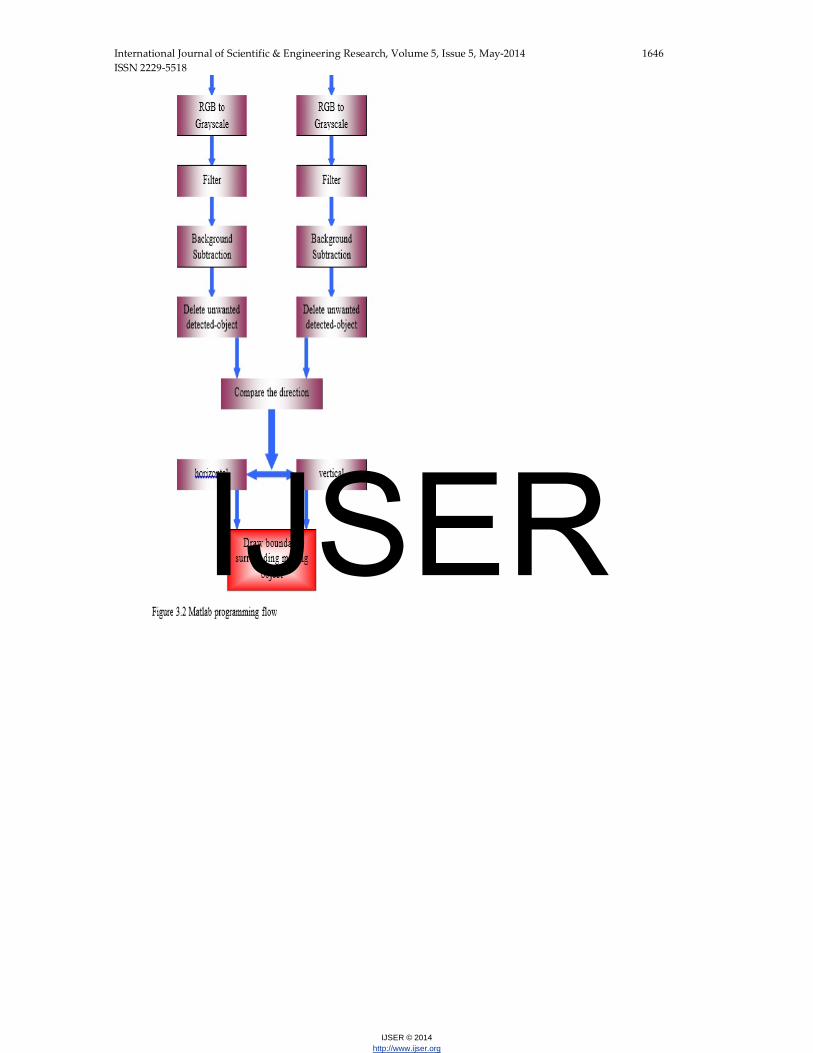
The algorithm flow which is written in Matlab
is shown in Figure 3.2. The processing of the image
which is implemented in matlab programming is done
by taking 4 frames to compute in two sets of
computation. The computation outputs of both sets are
compared and the moving object detection is decided
based on this.
IJSER
International Journal of Scientific & Engineering Research, Volume 5, Issue 5, May-2014 1646 ISSN 2229-5518
IJSER © 2014 http://www.ijser.org
IJSER
International Journal of Scientific & Engineering Research, Volume 5, Issue 5, May-2014 1647 ISSN 2229-5518
IJSER © 2014 http://www.ijser.org
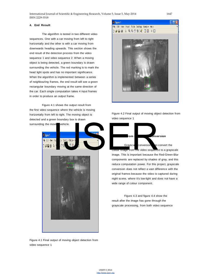
4. End Result
The algorithm is tested in two different video
sequences. One with a car moving from left to right
horizontally and the other is with a car moving from
downwards heading upwards. This section shows the
end result of the detection process from the video
sequence 1 and video sequence 2. When a moving
object is being detected, a green boundary is drawn
surrounding the vehicle. The red marking is to mark the
head light spots and has no important significance.
When the algorithm is implemented between a series
of neighbouring frames, the end result will see a green
rectangular boundary moving at the same direction of
the car. Each single computation takes 4 input frames
in order to produce an output frame.
Figure 4.1 shows the output result from
the first video sequence where the vehicle is moving
horizontally from left to right. The moving object is
detected and a green boundary box is drawn
surrounding the moving vehicle.
Figure 4.1 Final output of moving object detection from
video sequence 1
Figure 4.2 Final output of moving object detection from
video sequence 1
4.2 Result from Grayscale Conversion
Grayscale conversion is to convert the
colour image from the video sequence to a grayscale
image. This is important because the Red-Green-Blur
components are replaced by shades of gray, and this
reduce computation power. For this project, grayscale
conversion does not reflect a vast difference with the
original frames because the video is captured during
night scene, where it’s low-light and does not have a
wide range of colour component.
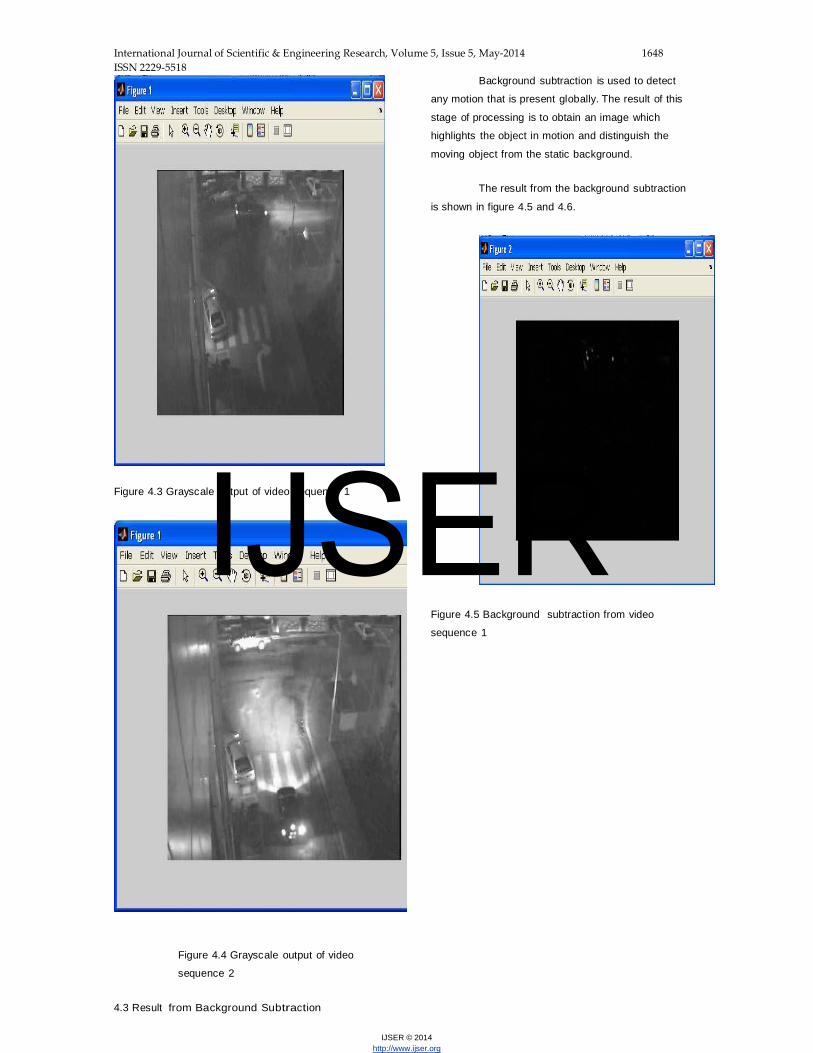
Figure 4.3 and figure 4.4 show the
result after the image has gone through the
grayscale processing, from both video sequence
IJSER
International Journal of Scientific & Engineering Research, Volume 5, Issue 5, May-2014 1648 ISSN 2229-5518
IJSER © 2014 http://www.ijser.org
Figure 4.3 Grayscale output of video sequence 1
Figure 4.4 Grayscale output of video
sequence 2
4.3 Result from Background Subtraction
Background subtraction is used to detect
any motion that is present globally. The result of this
stage of processing is to obtain an image which
highlights the object in motion and distinguish the
moving object from the static background.
The result from the background subtraction
is shown in figure 4.5 and 4.6.
Figure 4.5 Background subtraction from video
sequence 1
IJSER

International Journal of Scientific & Engineering Research, Volume 5, Issue 5, May-2014 1649 ISSN 2229-5518
IJSER © 2014 http://www.ijser.org
Figure 4.6 Background subtraction output from video
sequence 2
4.4 Result from Thresholding
From background subtraction stage, the
moving object does not show a clear contrast
between the moving object versus the background.
This does not mean the information is not there. The
lack of contrast is because the nature of human
eyes which does not read a picture by reading it’s
pixels values. The result of thresholding process is
shown in Figure 4.7 and 4.8. When thresholding is
applied, the contrast between moving lights or
object and the static background is enhanced and
become more apparent and obvious.
Figure 4.7 Result from thresholding from video
sequence 1
Figure 4.8 Result from thresholding from video
sequence 2
4.5 Result from Detection Mechanism
The detection process is basically the brain
behind the algorithm. The first stage is to cater for
video sequence 1 where the brake lights are being
deleted off. Besides, noise which might be present in
the scene is also being removed. At the end result, a
IJSER

International Journal of Scientific & Engineering Research, Volume 5, Issue 5, May-2014 1650 ISSN 2229-5518
IJSER © 2014 http://www.ijser.org
clean image is expected and a boundary can be drawn
at the final stage, to indicate the location of the moving
object. The end result mentioned from video
sequence 1 is shown in Figure 4.9.
Figure 4.9 Detection output from video sequence 1
The next figure, that is figure 4.10 shows
video sequence 2, where noise is present. Noise can be
reflected lights from the surroundings which are not
wanted. Beside both left and right back light, the brake
light can be seen or detected too.
Figure 4.10 Detection output from video sequence 2
After going through some clean up, the out
image is much cleaner in order to draw the
rectangular boundary surrounding the moving object.
A cleaned up image is shown in Figure 4.11.
Figure 4.11 Detection output from video sequence 2
after cleaning up
5. Conclusion
IJSER

International Journal of Scientific & Engineering Research, Volume 5, Issue 5, May-2014 1651 ISSN 2229-5518
IJSER © 2014 http://www.ijser.org
Generally, this project is to develop an
algorithm for a moving object detection, particularly for
night scene. This algorithm is successfully
implemented using Matlab integrated development
environment. As a result, the algorithm is able to detect
a moving object that is moving from a horizontal
direction or a vertical direction, as long as the targeted
object emerged fully within the camera view range.
The input for this project is two video
sequences which were captured via infrared-sensitive
camera. The first step of the algorithm is to sample
the video sequence into static frames. This train of
frames is originally in red-green-blue (RGB). To ease
computation, then RGB frames are converted to
grayscale images. Each frames is then being put into
the filtering process, background subtraction,
thresholding and finally, the detection process that
identify the moving vehicle based on the headlights
and backlights that are being detected in the previous
processing stages. The most vital process is the final
stage of processing where the robustness and
intelligence of the system is reflected in this stage.
The main objective of this project is to
develop an algorithm that is able to work in a low
light scene to detect moving object, specifically
moving vehicles. Although the algorithm has a
reasonable success rate, the algorithm has
various limitation and susceptible to the image
quality. Thus, the performance can be improved
and the present algorithm can be further
developed for better reliability and effectiveness.
5.1 Recommondations And future Scope
There are several ways that can be
considered to improve the algorithm. Other image
processing technique or mechanism can be
incorporated to increase the robustness and
performance of this project.
• Object Tracking
Object tracking can be incorporated in the
algorithm to increase the robustness of the detection
process. Object tracking is able to detect the moving
vehicle that is partially emerged in the camera view
range. The tracking algorithm can be done using
motion segmentation, which segments moving
objects from the stationary background. A discrete
feature-based approach is applied to compute
displacement vectors between consecutive frames.
With this, the moving object can be detected as well
as their associated tracks.
• Object Classification
Using object classification statistics,
occlusion effects can be reduced effectively.
Object classification algorithm can improve the
performance of monitoring and detecting the
moving object. This can be done by using motion
segmentation and tracking technique.
6. REFERENCE
1. Digital Image Processing (Rafael C. Gonzalez &
Richard E. Woods, 2002 Prentice Hall)
2. Fundamentals of Digital Image Processing (Anil K.
Jain, Prentice Hall)
3. Moving object detection in wavelet compressed
video [Toreyin, B.U.; Cetin, A.E.; Aksay, A.; Akhan,
M.B. ]. Published in Signal Processing and
Communications Applications Conference, 2004.
Proceedings of the IEEE 12th Volume , Issue , 28-30
April 2004 Page(s): 676 - 679.
4. Tomasi, C., Kanade, T., “Detection and tracking
of pointfeatures”, Technical Report CMU-CS-91-132,
Carnegie Mellon University, Apr. 1991.
5. On-Road Vehicle Detection: A Review [Zehang
Sun, Member, IEEE, George Bebis, Member, IEEE,
and Ronald Miller]. Published IEEE Transactions On
Pattern Analysis And Machine Intelligence, Vol. 28,
No. 5, May 2006
6. Background subtraction techniques: a review
[Piccardi, M. ]. Published by Systems, Man and
Cybernetics, 2004 IEEE International Conference
On page(s): 3099- 3104 vol.4 10-13 Oct. 2004
7. Scott E Umbaugh (1998). Computer Vision and
Image Processing. London,UK: Prentice Hall
International,Inc
IJSER

International Journal of Scientific & Engineering Research, Volume 5, Issue 5, May-2014 1652 ISSN 2229-5518
IJSER © 2014 http://www.ijser.org
.
IJSER

International Journal of Scientific & Engineering Research, Volume 5, Issue 5, May-2014 1653 ISSN 2229-5518
IJSER © 2014 http://www.ijser.org
IJSER

International Journal of Scientific & Engineering Research, Volume 5, Issue 5, May-2014 1654 ISSN 2229-5518
IJSER © 2014 http://www.ijser.org
IJSER