Detailed Design Review - EDGE
97
Detailed Design Review P14474 Kyle Abbott Mitch Sedore Brian Brenner Anushka Kalicharan Jake Manley
Transcript of Detailed Design Review - EDGE

Detailed Design Review
P14474Kyle AbbottMitch SedoreBrian BrennerAnushka KalicharanJake Manley

Agenda● Customer Requirements● Engineering
Requirements● System Overview● Controller● Motor
○ Driver○ Encoder○ Gearbox○ Motor Mount
● Valve○ Coupler
● Pressure Transducers● Piping and Fitting
○ Enclosure○ Manifold
● Bill of Materials● Engineering Drawings● Schedule

System Customer Requirements

System Engineering Requirements

System Overview
● Components:○ Piping and Fittings○ Valves○ Pressure transducers and manifold○ Motor and motor mount○ System Controller

Overall Assembly

System Diagram

Ruggedized Data Acquisition Unit with Real Time Operating System

CompactRIO Integrated Systems with Real-Time Controller and Reconfigurable Chassis

Chassis Specifications
● 4 Module Slots● 400 MHz Processor● Spartan-6 LX25 FPGA● 128 MB DRAM● 256 MB Nonvolatile Storage● 10/100 BASE-TX Ethernet Port● RS232 Serial Port

FPGA Specifications
● 24051 Logic Cells● 38 Multipliers● 936 KB RAM

Embedded Software Diagram

Analog Input Module NI 9215

Analog Input Module Specifications● 4 Voltage Inputs● 100 kS/s per Channel● Channel Independent Analog to Digital
Converters● 16-bit Resolution● Built-In Signal Conditioning● Channel-to-Earth Double Isolation Barrier● Screw Terminal Connections
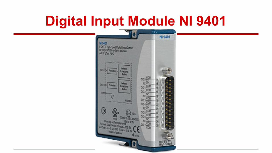
Digital Input Module NI 9401

Digital Input Module Specifications● DSub Connector with Screw Terminal Adapter● 8 5V/TTL Sinking/Sourcing Bidirectional Digital
I/O Ports● 100 ns Propagation Delay● 9 MHz Switching Frequency using All 8 Ports as
Inputs● 500 ns Max Input Rise/Fall Time● ±30 V Max Overprotection on One Channel at a
Time

Digital Output Module NI 9472

Digital Output Module Specifications
● 8 Digital Output Channels● 100 ns Propagation Delay● 6 to 30V, Current Sourcing Digital Outputs● Screw Terminal Connections● 750 mA/Channel


Controller Engineering Requirements

Controller Risk Analysis

Bill of Materials for Rugged DAQ Unit

Motor
● Stepper motor chosen to control valve○ Requirements:
■ Sufficient torque■ Water resistant■ Precise control

Motor: Anaheim Automation NEMA 23Y65
● IP65 Rated○ Splash Proof and designed for humid environments
● 175 oz inches max output torque

Torque Requirements
● Based on valve opening torque○ 10000 PSI =
11 in-lb■ 176 oz-in
● Taken from manufacturer handbook

Motor: Anaheim Automation NEMA 23

Motor Wiring Diagram

Bipolar Microstep Driver Pack DPY50001

Current Sourcing Driver Pack Wiring

Electrical Specifications

Motor and Control Pin Descriptions

Steps per Revolution Selection Switch Panel Configurations

Output Current Selection via Potentiometer

Gearbox
● 3:1 reducing gearbox added:○ Finer valve control
■ Standard motor step is 1.8 degrees● .6 degrees per step with gearbox● Approximately 4.1 psi/step
○ Increased side loading capability■ Potential side loading from motor-valve
misalignment wears motor bearings■ Gearbox bearings carry much higher load
○ Increased margin of safety on valve opening torque

Gearbox

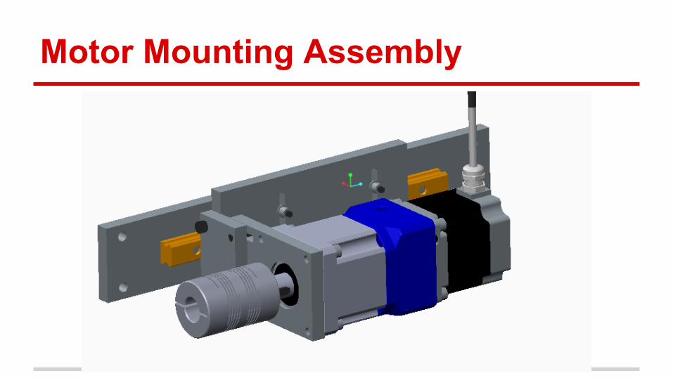
Motor Mounting Assembly
● Requirements○ Support motor weight and torque loads○ Adjustable installation to accommodate variation in
plumbing/valve installation location○ Ability to transverse along valve stem during opening
and closing
Motor Mounting Assembly

Motor Mounting Assembly

Motor Mounting Assembly
● Minimum of ¾ inch freedom in all 3 directions
● Shaft coupler allows for 3 degrees shaft angle misalignment

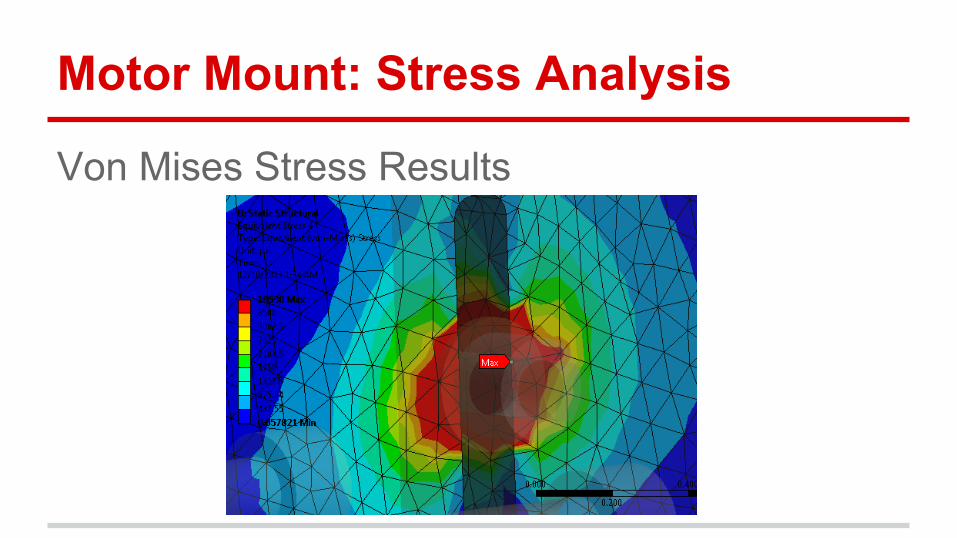
Motor Mount: Stress Analysis● Analysis done in Ansys Workbench (V 14.5.7)● Moment applied to motor flange● Motor and gearbox weight applied to motor flange ● Fixed supports at linear slide mounts● Bolt pretensions at support plate
● Material: 6061-T6 aluminum plate○ 42 KSI Ultimate, 35 KSI Yield

Motor Mount: Stress Analysis
Overview

Motor Mount: Stress Analysis
Overview
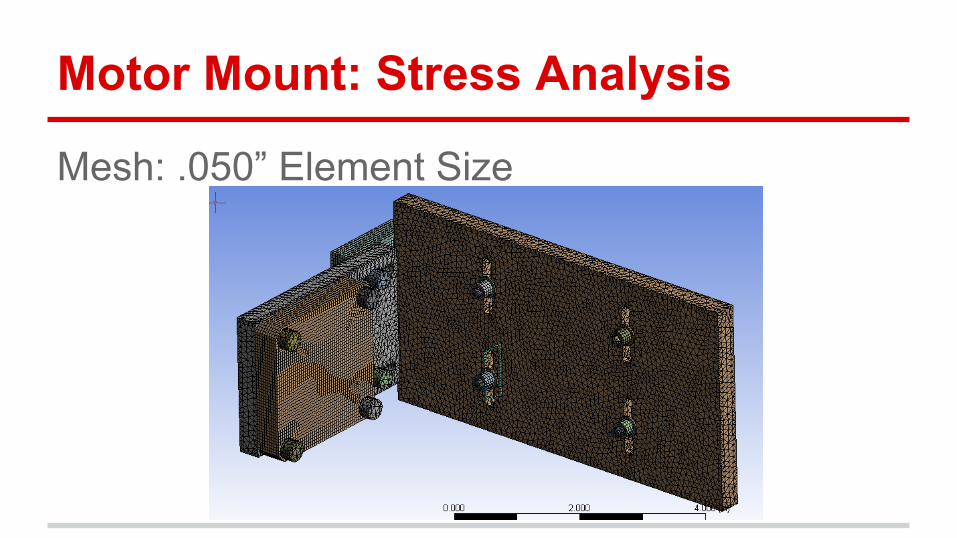
Motor Mount: Stress Analysis
Mesh: .050” Element Size

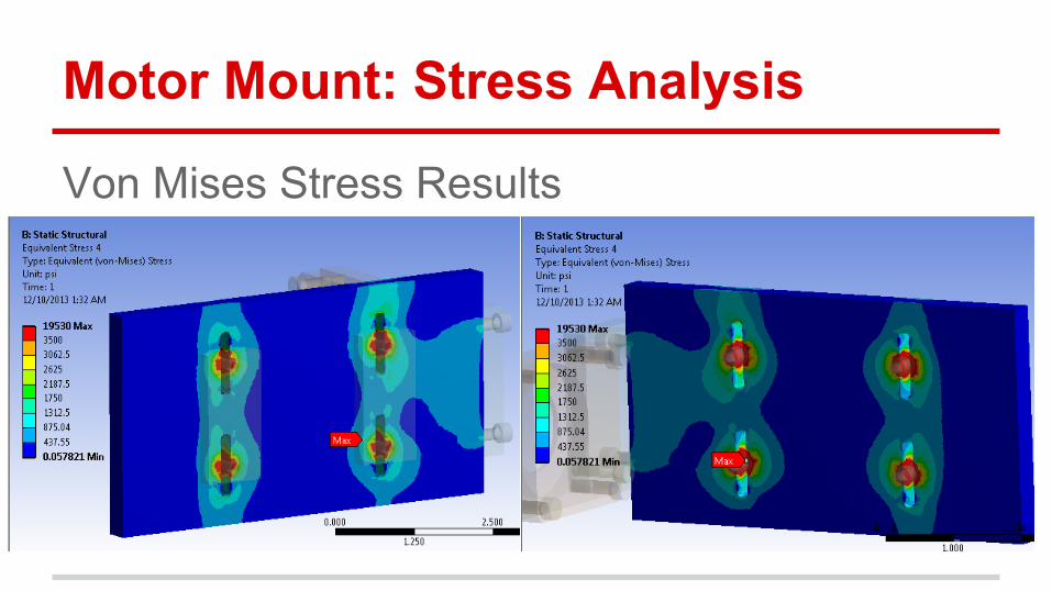
Motor Mount: Stress Analysis
Von Mises Stress Results

Motor Mount: Stress Analysis
Von Mises Stress Results
Motor Mount: Stress Analysis
Von Mises Stress Results
Motor Mount: Stress Analysis
Von Mises Stress Results

Motor Mount Stress Analysis● Results:
○ Majority of part well over F.O.S. of 2 (17.5 KSI)○ Max stress exceeds F.O.S. of 2 allowable but is in
compression■ Mostly caused by bolt pretension and not
component loading

Encoder: ENC-A3I Single-Ended High Resolution w/ Index Channel

Encoder: Engineering Requirements

Encoder: FMEA

Encoder- BOM
Company Part Part Number Quantity Unit
Price Subtotal Tax & Shipping Total
Anaheim Automation
ENC-A3I Single-Ended High Resolution w/ Index Channel
ENC-A3I-0400-984-H-T
1 $96 $96 $96

Valve● Swagelok IPT series high
pressure needle valve○ 4-5 turns to open○ 10000 PSIG operating pressure○ CV value of 5.1
■ High flow, low pressure drop● Lowers minimum test enclosure
pressure

Valve
● Pressure drop across valve:○ a
■ Q (gpm), ΔP (psi)● 11.1 psi pressure drop
○ At 17 gpm max flow
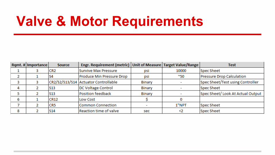
Valve & Motor Requirements

Valve and Motor FMEA

Coupler Selection
● Flex Coupling - 3 degrees● Clamp on type - provides freedom in
mounting and adequate torque

Pressure Transducer Specs● NIST Certified● 0-5Vdc● Stainless Steel● Life of 10 million cycles● Accuracy
○ 10,000psi= +/- 0.25%○ 5,000psi and 1,000psi= +/-0.8%
● Response time of less than 1 millisecond● 5ft 3 conductor cable● 5 Point NIST traceable included

Pressure Transducer Sensitivity Calculations
● 0 - 10,000 psi Transducer○ 1 volt = 2000 psi○ Accuracy = ± 25 psi○ Step Voltage = 12.5 mV per 25 psi
● 0 - 5,000 psi Transducer○ 1 volt = 1000 psi○ Accuracy = ± 4 psi○ Step Voltage = 4mV per 4 psi
● 0 - 1,000 psi Transducer○ 1 volt = 200 psi○ Accuracy = ± 0.8 psi○ Step Voltage = 4mV per 0.8 psi

Pressure Transducers- Eng. Reqmts

Pressure Transducer Risk Analysis

Pressure Transducer BOM
Omega10,000psi pressure
transducer w/ 5' cable PX309-10KG5V 1 $225.00 $225.00 $225
Omega5,000psi pressure transducer
w/ 5' cable PX309-5KG5V 1 $225.00 $225.00 $225
Omega1,000psi pressure transducer
w/ 5' cable PX309-1KG5V 1 $225.00 $225.00 $225
Company Part Part Number QuantityUnit Price Subtotal
Tax & Shipping Total

Piping and Fittings
● 1” XXH Black Pipe○ Working Pressure ~ 24,000
psi● Class 6000 Fittings
○ Equivalent to XXH piping○ x3 Elbows○ x3 Tees

Working Pressure Calculation
The maximum working pressures were found for various materials. The safety factor used is 2.5, determined by ASME Power Piping code B31.3.
Using the following equation:

Working Pressure Calculation

Calculations
Pressure drop calculations through drain pipe

Piping and Fittings- Eng. Reqmts

Piping and Fittings Risk Analysis
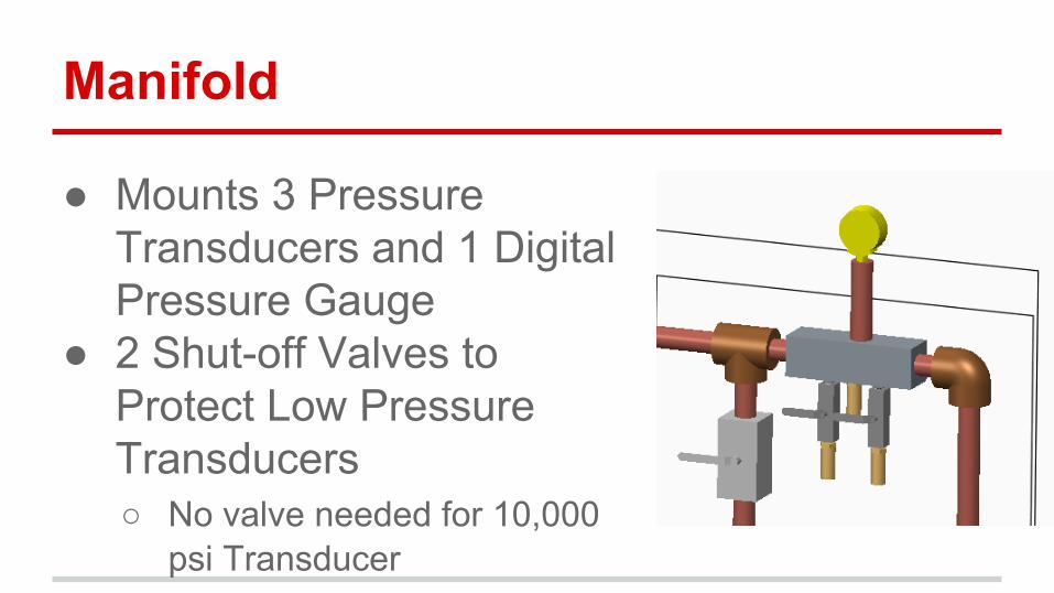
Manifold
● Mounts 3 Pressure Transducers and 1 Digital Pressure Gauge
● 2 Shut-off Valves to Protect Low Pressure Transducers○ No valve needed for 10,000
psi Transducer

Manifold FMEA and Risk Analysis

Manifold: Stress Analysis
● Analysis done in Ansys Workbench (V 14.5.7)
● 10000 PSI on all wetted surfaces● Blow-out loads on all threaded joints● Supports at 1” pipe joints
● Material: 7075-T6 aluminum○ 70 KSI Ultimate, 59 KSI Yield

Manifold: Stress Analysis
● Setup

Manifold Stress Analysis
● Mesh

Manifold: Stress Analysis
Von Mises Stress Results

Manifold: Stress Analysis
Stress Peak

Manifold: Stress Analysis● Results:
○ Majority of part well over F.O.S. of 2 (29.5 KSI)○ Max stress represents 1.27 F.O.S.
● Recommend development part in 7075 aluminum○ Ease of machining○ Cost
● Recommend production part in 15-5 PH stainless steel or equivalent strength stainless alloy○ Heat treated to ~100 KSI tensile yield or better

Enclosure: Overview
● Protect components from water spray and test part failure○ Vulnerable components include:
■ Motor■ Encoder■ Pressure Transducers

Enclosure FMEA and Risk Analysis

Enclosure: Geometry

Enclosure: Geometry● Hinged door to allow
quick access to transducer shut-off valves

Bill of Materials

Bill of Materials cont.

Bill of Materials cont.

P14474_101

P14474_103

P14474_105

P14474_107
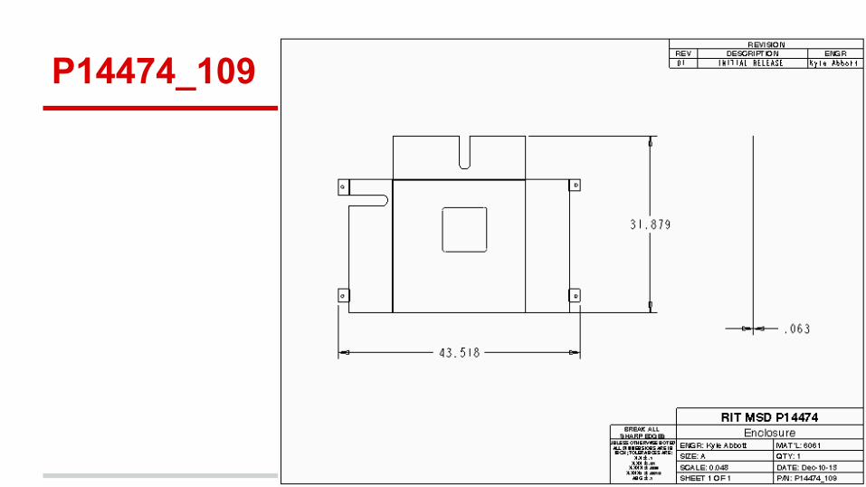
P14474_109

P14474_111
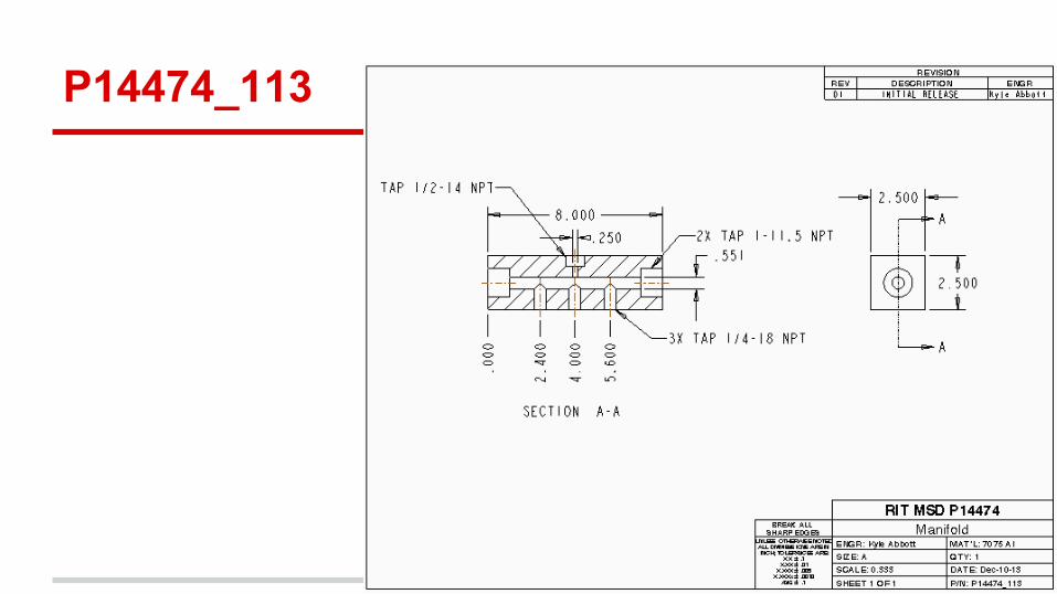
P14474_113

MSD II Schedule

Questions?

Alternative Coupler: P14474_115

Alternative Coupler: P14474_117

Components