DETAIL SPECIFICATION ANTI-G GARMENT, CUTAWAY, CSU-13B/P
55
INCH POUND MIL-DTL-83406C 24 March 2006 . SUPERSEDING MIL-A-83406B(USAF) 3 September 1975 DETAIL SPECIFICATION ANTI-G GARMENT, CUTAWAY, CSU-13B/P Reactivated for new design after 24 March 2006. This specification is for an Aviation Critical Safety Item (CSI)/Flight Safety Critical Aircraft Part (FSCAP) and the acquisition process must comply with the DoD Materiel Management Regulation – DoD 4140.1-R Comments, suggestions, or questions on this document should be addressed to: ASC/ENOI, Wright-Patterson AFB OH 45433-7101 or e-mail to [email protected] . Since contact information can change, you may want to verify the currency of this address information using the ASSIST Online database at http://assist.daps.dla.mil . AMSC N/A FSC 8475 DISTRIBUTION STATEMENT A. Approved for public release; distribution is unlimited. Downloaded from http://www.everyspec.com
Transcript of DETAIL SPECIFICATION ANTI-G GARMENT, CUTAWAY, CSU-13B/P

INCH POUND
MIL-DTL-83406C 24 March 2006
. SUPERSEDING MIL-A-83406B(USAF) 3 September 1975
DETAIL SPECIFICATION
ANTI-G GARMENT, CUTAWAY, CSU-13B/P
Reactivated for new design after 24 March 2006.
This specification is for an Aviation Critical Safety Item (CSI)/Flight Safety Critical Aircraft Part (FSCAP) and the acquisition process must comply with the DoD Materiel Management
Regulation – DoD 4140.1-R
Comments, suggestions, or questions on this document should be addressed to: ASC/ENOI, Wright-Patterson AFB OH 45433-7101 or e-mail to [email protected]. Since contact information can change, you may want to verify the currency of this address information using the ASSIST Online database at http://assist.daps.dla.mil.
AMSC N/A FSC 8475
DISTRIBUTION STATEMENT A. Approved for public release; distribution is unlimited.
Downloaded from http://www.everyspec.com

MIL-DTL-83406C
2
This specification is approved for use by all Departments and Agencies of the Department of Defense (DoD).
1. SCOPE
1.1 Scope. This specification covers the CSU-13B/P anti-g garment which is designated as a critical safety item.
1.2 Classification. Anti-g garments are of the following sizes, as specified (see 6.2 and 6.6):
Small regular (SR) Medium regular (MR) Large regular (LR) Large extra long (LXL)
Small long (SL) Medium long (ML) Large long (LL)
2. APPLICABLE DOCUMENTS
2.1 General. The documents listed in this section are specified in sections 3 and 4 of this specification. This section does not include documents cited in other sections of this specification or recommended for additional information or as examples. While every effort has been made to ensure the completeness of this list, document users are cautioned that they must meet all specified requirements of documents cited in sections 3 and 4 of this specification, whether or not they are listed.
2.2 Government documents.
2.2.1 Specifications, standards, and handbooks. The following specifications, standards, and handbooks form a part of this document to the extent specified herein. Unless otherwise specified, the issues of these documents are those cited in the solicitation or contract.
FEDERAL SPECIFICATIONS
V-T-295 Thread, Nylon
FEDERAL STANDARDS
FED-STD-4 Glossary of Fabric Imperfections FED-STD-595 Colors Used In Government Procurement
COMMERCIAL ITEM DESCRIPTIONS
A-A-50195 Thread, Aramid A-A-55126 Fastener Tapes, Hook and Loop, Synthetic A-A-55621 Fasteners, Snap, Style 3 Pronged Ring Head Type (16 Ligne) A-A-55634 Zippers (Fasteners, Slide Interlocking) A-A-55809 Insulation Tape, Electrical, 600V, Polyvinyl Chloride, Pressure-
Sensitive Adhesive
Downloaded from http://www.everyspec.com

MIL-DTL-83406C
3
DEPARTMENT OF DEFENSE SPECIFICATIONS
MIL-PRF-5038 Tape, Textile and Webbing, Textile, Reinforcing, Nylon MIL-W-5664 Webbing, Textile, Elastic MIL-R-6855 Rubber, Synthetic, Sheets, Strips, Molded or Extruded Shapes,
General Specification For MIL-DTL-10884 Fasteners, Snap MIL-DTL-32075 Label: for Clothing, Equipage, and Tentage, (General Use) MIL-T-38328 Tape, Textile, Nylon, Aromatic, Nonmelting, Reinforcing MIL-C-43204 Cloth, Spacer (Olefin) MIL-L-43283 Leather, Calfskin, Kip, and Cattlehide for Footwear Uppers, Chrome
Tanned MIL-W-81116 Webbing, Textile, Polyamide, High Temperature Resistant, Loop MIL-C-83242 Cord, Aromatic Polyamide, Nonmelting (Inactive) MIL-C-83390 Connector, Hose, Quick-Acting, Male, Anti-G Garment (Inactive) MIL-C-83429 Cloth, Plain and Basket Weave, Aramid MIL-C-83489 Cloth, Coated, Nylon, Polyurethane Coated
DEPARTMENT OF DEFENSE STANDARDS
MS 27755 Connector, Hose Quick Disconnect, Female, Anti “G” Suit (Copies of these documents are available online at http://assist.daps.dla.mil/quicksearch/ or http://assist.daps.dla.mil or from the Standardization Document Order Desk, 700 Robbins Avenue, Building 4D, Philadelphia, PA 19111-5094.)
2.2.2 Other Government documents, drawings, and publications. The following other Government documents, drawings, and publications form a part of this document to the extent specified herein. Unless otherwise specified, the issues are those cited in the solicitation or contract.
AIR FORCE DRAWINGS
71380 Patterns, CSU-13B/P anti-g garment, Size Small Regular 71381 Patterns, CSU-13B/P anti-g garment, Size Small Long 71382 Patterns, CSU-13B/P anti-g garment, Size Medium Regular 71383 Patterns, CSU-13B/P anti-g garment, Size Medium Long 71384 Patterns, CSU-13B/P anti-g garment, Size Large Regular 71385 Patterns, CSU-13B/P anti-g garment, Size Large Long 71386 Patterns, CSU-13B/P anti-g garment, Miscellaneous All Sizes 74204 Spacer, Tube – anti-g garment 74206 Pattern, anti-g garment, CSU-13B/P, Size Large Extra Long 200518653 Source Control Drawing- Fastener, Slide
(Copies of these documents are available from the Defense Supply Center Philadelphia, Clothing and Textiles Directorate, ATTN: DSCP-CBTC, (Bldg 6), 700 Robbins Ave., Philadelphia, PA. 19111-5092 or for DoD personnel they are available online at www.jedmics.net.)
Downloaded from http://www.everyspec.com

MIL-DTL-83406C
4
2.3 Non-Government publications. The following documents form a part of this document to the extent specified herein. Unless otherwise specified, the issues of documents are those cited in the solicitation or contract.
AEROSPACE INDUSTRIES ASSOCIATION (AIA)
NATIONAL AEROSPACE STANDARDS (NAS) NAS 397 Clamp – Ratchet, One Piece (DoD Adopted) NASM 20230 Grommets, Metallic, Plain and Spur, with Washers, Type I and
Type III (DoD Adopted) NASM 27980 Fasteners, Snap, Style 2 (Regular Wire Spring Clamp Type) (DoD
Adopted) NASM 27983 Fasteners, Snap, Style 4 (Three Way Locking Type) (DoD Adopted)
(Copies of these documents are available from www.aia-aerospace.org or Aerospace Industries Association of America Inc., 1000 Wilson Blvd, Suite 1700, Arlington VA 22209-3901.)
AMERICAN SOCIETY FOR QUALITY (ASQ) ANSI/ASQ Z1.4 Sampling Procedures and Tables for Inspection by Attributes
(Copies of this document are available from www.asq.org or the American Society for Quality, 600 North Plankinton Ave., Milwaukee WI 53203-2914.)
ASTM INTERNATIONAL ASTM A 313/A 313M Standard Specification for Stainless Steel Spring Wire ASTM D 6193 Standard Practice for Stitches and Seams
(Copies of these documents are available from www.astm.org or ASTM International, 100 Bar Harbour Dr., West Conshohocken PA 19428-2959.)
THE PARACHUTE INDUSTRY ASSOCIATION (PIA) PIA-C-3953 Cloth, Duck, Nylon PIA-W-4088 Webbing, Textile, Woven Nylon
(Copies of these documents are available from www.pia.com or the Parachute Industry Association (PIA), 3833 West Oakton St., Skokie IL 60076.)
SAE INTERNATIONAL SAE AMS-T-22085 Tapes, Pressure-Sensitive, Adhesive, Preservation and Sealing
(Copies of this document are available from or www.sae.org or SAE World Headquarters, 400 Commonwealth Dr., Warrendale PA 15096-0001.)
Downloaded from http://www.everyspec.com

MIL-DTL-83406C
5
2.4 Order of precedence. In the event of a conflict between the text of this document and the references cited herein, the text of this document takes precedence. Nothing in this document, however, supersedes applicable laws and regulations unless a specific exemption has been obtained.
3. REQUIREMENTS
3.1 First article. When specified (see 6.2), a sample shall be subjected to first article inspection in accordance with 4.2.
3.2 Qualification. The anti-g garments furnished under this specification shall be products that are authorized by the qualifying activity for listing on the applicable qualified products list before contract award (see 4.3 and 6.3).
3.3 Recycled, recovered, or environmentally preferable materials. Recycled, recovered, or environmentally preferable materials should be used to the maximum extent possible, provided that the material meets or exceeds the operational and maintenance requirements, and promotes economically advantageous life cycle costs.
3.4 Materials and parts. Except for the metallic materials and parts, the materials and parts of the anti-g garment shall have been manufactured not more than 12 months prior to the date of delivery of the anti-g garment.
3.4.1 Basic materials
3.4.1.1 High temperature resistant cloth. Except for the bladder, the basic fabric for the anti-g garment shall conform to type II of MIL-C-83429 and shall be sage green, USAF color shade No. 1590 (see 6.3).
3.4.1.2 Polyurethane coated nylon cloth. The material for the bladder, including the attachment patches, reinforcement of inflation tubes, external covering, and checklist retainer area of thigh, shall conform to type I of MIL-C-83489.
3.4.2 Reinforcements and bindings. Unless otherwise specified herein, the reinforcements shall be made of the basic fabric specified in 3.4.1.1. The 5/16-inch wide (finished), centerfold, bias binding shall be 45 degrees bias cut 1-1/4 inches to 1-3/8 inches wide from the basic fabric specified in 3.4.1.1.
3.4.3 Adjustment laces and lanyard. The cord for the lanyard and for the adjustment laces shall conform to type I of MIL-C-83242 and shall approximately match the shade of the basic material in 3.4.1.1.
Downloaded from http://www.everyspec.com

MIL-DTL-83406C
6
3.4.4 Slide fasteners. The slide fasteners shall conform to table I of this specification and AF Drawing 200518653 except as otherwise specified herein. The slide fasteners shall be brass with a tab pull. The tape and the bead of all size fasteners (including the body opening) shall be a high temperature resistant polyamide material that has been dyed to match the color of the basic fabric specified in 3.4.1.1. The tape of the slide fastener shall have colorfastness in accordance with A-A-55634, except that fair colorfastness in lieu of good colorfastness to light will be acceptable. The finish of the chain and the other metal components shall be dark oxidized. All automatic-locking sliders shall have a pin-type locking device.
3.4.5 Spacer material. The spacer material for the bladder shall conform to type III of MIL-C-43204
TABLE I. Slide fasteners.
GARMENT SIZE
CONTROL DRAWING
LOCATION
SR 200518653-01 Thigh take-up
SL/ML/LL/LXL 200518653-03 Thigh take-up
MR/LR 200518653-05 Thigh take-up
ALL 200518653-07 Pocket
ALL 200518653-11 Body
SR 200518653-13 Left leg
SR 200518653-15 Right leg
SL 200518653-17 Left leg
SL 200518653-21 Right leg
MR 200518653-23 Left leg
MR 200518653-25 Right leg
ML 200518653-27 Left leg
ML 200518653-31 Right leg
LR 200518653-33 Left leg
LR 200518653-35 Right leg
LL 200518653-37 Left leg
LL 200518653-41 Right leg
LXL 200518653-43 Left leg
LXL 200518653-45 Right leg
Downloaded from http://www.everyspec.com

MIL-DTL-83406C
7
3.4.6 Stiffeners. The stiffeners for the slide fasteners, front and back body, shall be made of nylon cloth conforming to class 2 of PIA-C-3953.
3.4.7 Aromatic polyamide tape. The slide fastener’s tape for the pull thong, loops for the slide fasteners, and the hanger shall be 5/16-inch wide, conforming to type VI of MIL-T-38328 and shall approximately match the color of the basic fabric specified in 3.4.1.1.
3.4.8 Nylon webbing. The webbing for the knife pocket reinforcement shall be untreated, conform to type XII of PIA-W-4088, and match the shade of the basic material in 3.4.1.1 or be natural.
3.4.9 Wrapping tape for anti-g garment hose assembly. The tape for wrapping the anti-g garment hose assembly shall be black and 1-inch wide conforming to A-A-55809.
3.4.10 Lacer loops. The tape for the lacer loops shall conform to MIL-W-81116, except that the sleeve may have 16 carriers in lieu of 20 carriers; the length shall be 39-1/2 inches, in lieu of 45 inches for each yard of webbing; and the color shall match the color of the basic fabric specified in 3.4.1.1.
3.4.11 Thread. Unless otherwise specified herein, the thread for all sewing operations shall conform to A-A-50195, type: soft, size: denier, 800d, Tex 80 and shall approximately match the color of the basic fabric specified in 3.4.1.1. (Note: This thread may be used to sew the nylon mesh cloth (see 3.4.21) in lieu of the thread conforming to type I, class A, size E of V-T-295, which is specified in AF Drawing 74204.)
3.4.12 Snap fasteners. Except for the knife pocket, the snap fasteners shall conform to style 3, finish A of A-A-55621 (pronged ring A-A-55621-1B, socket A-A-55621-2B, stud A-A-55621-4B, and eyelet A-A-55621-5B). The snap fastener for the knife pocket shall conform to style 4, construction A of NASM27983 (button NASM27983-1, socket NASM27983-2, stud NASM27983-3, and eyelet NASM27983-4).
3.4.13 Grommet. The grommet shall be size 00 conforming to NASM20230-B20 and shall be oxidized a black color.
3.4.14 Fastener tape. The hook and pile fastener tapes shall conform to type I, class 2 of A-A-55126. The color of the pile fastener tape and the hook fastener tape shall approximately match the color of the basic fabric specified in 3.4.1.1 (see 6.3). With the exception of the checklist retainer’s pile fastener tape, the fastener tape shall be 1 inch wide. The pile fastener tape for the checklist retainer shall be 2 inches wide.
Downloaded from http://www.everyspec.com

MIL-DTL-83406C
8
3.4.15 Adhesive. The adhesive for cementing the spacer material to the coated bladder material shall be a one-part polyurethane cement (see 6.6).
3.4.16 Connector. The connector shall conform to MIL-C-83390.
3.4.17 Rubber sleeve. The rubber sleeve for the connector shall be tubular conforming to class 2, type B, grade 40 or 60 of MIL-R-6855, shall be 3 (±1/16) inches long, shall have an outer diameter of 3/4 (±1/16) inch, and shall have a wall thickness of 1/8 (±1/32) inch. No silicone or any other lubricant shall be applied to either the rubber sleeve or the connector prior to assembling the rubber sleeve to the connector.
3.4.18 Clamps The clamps for securing the connector to the external tube shall conform to NAS 397-14 and NAS 397-16.
3.4.19 Leather reinforcement. The leather for the knife pocket reinforcement and the reinforcement patch over the inflation sleeve opening shall be black and shall conform to type 1 of MIL-L-43283, except that the thickness (ounces) shall be 2 to 2-1/2 ounces.
3.4.20 Springs for tube spacer. The material for the springs of the tube spacer shall be a round, 0.016-inch diameter, composition 304, wire with a minimum tensile strength of 306,000 psi and a maximum of 336,000 psi per ASTM A313/A313M.
3.4.21 Cloth for the tube spacer. The cloth for the tube spacer shall be polypropylene netting/mesh cloth with approximately 14 x 12 strands per inch; hole size .05 x .08, 0.020 inches thick, and 19 pounds per 1000 feet squared.
3.4.22 Rubber band. The rubber band (see figure 1) shall be 3/4 ±1/16 inch long and 0.035 inch (minimum) thickness. The color of the rubber band shall be black. The rubber shall comply with class 2, type A of MIL-R-6855.
3.5 Design. The anti-g garment shall be a wrap-around garment that extends from the body to over the calves of the wearer. It shall have an inflatable bladder that will cover the body and the leg areas of the wearer and a connector that will provide normal and emergency connection and disconnection of the bladder of the anti-g garment to and from the air pressure source. Both sides of the anti-g garment shall have external adjustment laces in the body, thigh, and calf areas; however, the adjustment laces shall have covers that can be unfastened for easy
Downloaded from http://www.everyspec.com

MIL-DTL-83406C
9
accessibility. The anti-g garment shall have a pocket on the calf of each leg, an elastic strap across the front face of each thigh, and a knife pocket on the front of the left thigh.
3.6 Construction. The anti-g garment shall be constructed as specified in table II; however, the manufacturer will not be required to follow the exact sequence of operations as listed therein.
3.6.1 Stitches and seams. Stitches and seams specified in table II shall conform to ASTM D 6193. Thread breaks and ends of all stitches and seams, if not caught in other stitches or seams, shall be securely backstitched reversing the stitching direction and sewing a continuous row of stitching superimposed on the original row of stitching for a distance of 1/2 inch. Stitching shall be considered caught in another stitch or seam if the two stitches are in opposite directions and superimposed directly on each other for at least one inch. The bartacks joining the spacer material and attaching the patches (see figures 2 and 3) shall be 3/4 inch long, centered, and shall contain approximately 32 stitches. Thread ends of all stitches inside and outside of the anti-g garment shall be trimmed flush with the fabric.
Downloaded from http://www.everyspec.com

MIL-DTL-83406C
10
FIGURE 1. Inflation tube assembly.
Downloaded from http://www.everyspec.com

MIL-DTL-83406C
11
FIGURE 2. Bartack (view A).
Downloaded from http://www.everyspec.com

MIL-DTL-83406C
12
FIGURE 3. Bladder construction (dimensions are in inches).
Downloaded from http://www.everyspec.com

MIL-DTL-83406C
13
TABLE II. Manufacturing operations.
No.
Description of Operation
Stitch Type
Seam & Stitching
Type
Stitches per Inch
1. Cut parts (see 3.11.1).
Cut the parts (including the bladders) of the anti-g garment in accordance with the patterns which show shape, size, directional lines, and marking for the proper assembly of the parts.
NOTE: Trimming of the body lacer covers, the thigh lacer covers, and the calf lacer covers will be permitted as specified in Operations 5.b, 6.b, and 6.e.
2. Shade mark.
Mark all parts to ensure a uniform shade throughout the anti-g garment.
3. Sear raw edges.
Sear the raw edges of all parts made of nylon material.
4. Sew loops of lacer loop tape.
Sew one row of stitching along each length of the lacer loop tape, through the base of each loop to prevent the loops from slipping.
301
SSa-1
10-12
5. Make body lace covers.
a. Select the fastener tapes for the body lacer covers in accordance with table III.
b. Trim the fastener tape, if necessary, to fit the body lacer covers at the top and the bottom. Turn each body lacer cover under 3/8 inch. Sew the hook fastener tape to each body lacer cover, at the pattern location, with a single row of stitching 1/16 inch from the edge on all four sides.
301 LSd-1 10-12
NOTE: Operation 5.b shall be performed before Operation 5.c so that the fastener tape will be sewn to the body lacer covers before the body lacer covers are bound.
Downloaded from http://www.everyspec.com

MIL-DTL-83406C
14
TABLE II. Manufacturing operations. – Continued
No.
Description of Operation
Stitch Type
Seam & Stitch Type
Stitches per Inch
5. Make body lace covers – contd.
c. Bind each body lacer cover at each end with 5/16 inch wide (finished) bias binding 1/16 (±1/32) inch from the edge. Before completing the stitching of the binding, at the top and the bottom of each lacer cover, fold the raw edges of each end of the binding (two ends per lacer cover) so that no raw edges are exposed (see turned-under binding in the sketch below). Complete the stitching of the binding to the fastener tape.
301 BSc-1 10-12
6. Make leg (thigh and calf) lacer covers.
a. Select the fastener tapes for the thigh lacer covers in accordance with table IV.
b. Trim the fastener tape, if necessary, to fit the thigh lacer covers at the top and the bottom. Turn each thigh lacer cover under 3/8 inch. Sew the hook fastener tape to each thigh lacer cover, at the pattern location, with a single row of stitching 1/16 inch from the edge on all four sides.
301 LSd-1 10-12
NOTE: Operation 6.b shall be performed before Operation 6.c so that the fastener tape will be sewn to the thigh lacer covers before the thigh lacer covers are bound.
c. Bind each thigh lacer cover at each end with 5/16 inch wide (finished) bias binding 1/16 (±1/32) inch from the edge. Before completing the stitching of the binding, at the top and the bottom of each lacer cover, fold the raw edges of each end of the binding (two ends per lacer cover) so that no raw edges are exposed (see turned-under binding sketch in Operation 5.c above). Complete the stitching of the binding to the fastener tape.
301 BSc-1 10-12
Downloaded from http://www.everyspec.com

MIL-DTL-83406C
15
TABLE II. Manufacturing operations. - Continued
No.
Description of Operation
Stitch Type
Seam & Stitch Type
Stitches per Inch
6. Make leg (thigh and calf) lacer covers – contd.
d. Select the fastener tapes for the calf lacer covers in accordance with table III.
e. Trim the fastener tape, if necessary, to fit the calf lacer covers at the top and the bottom. Turn each calf lacer cover under 3/8 inch. Sew the hook fastener tape to each calf lacer cover, at the pattern location, with a single row of stitching 1/16 inch from the edge on all four sides.
301 LSd-1 10-12
NOTE: Operation 6.e shall be performed before Operation 6.f so that the fastener tape will be sewn to the calf lacer covers before the calf lacer covers are bound.
f. Bind each calf lacer cover at each end with 5/16 inch wide (finished) bias binding 1/16 (±1/32) inch from the edge. Before completing the stitching of the binding, at the top and the bottom of each lacer cover, fold the raw edges of each end of the binding (two ends per lacer cover) so that no raw edges are exposed (see turned-under binding sketch in Operation 5.c above). Complete the stitching of the binding to the fastener tape.
301 BSc-1 10-12
7. Make thigh take-ups.
a. Select the slide fasteners for the thigh take-ups in accordance with table I. Zigzag stitch the tapes of the slide fasteners together from the bottom stop to the ends of the tapes.
301
or
401
SSa-1 20-26
b. Sew the 3/4 inch wide stiffener to the inside of the thigh take-up fly, right and left, on the long center line from end to end with a single row of stitching.
301 SSa-1 10-12
c. With the open end of the slide fastener at the top, center the top and bottom stops between the top and bottom of the thigh take-ups. Match the edges of the slide fastener tape with the edges of the thigh take-ups fly. Cut the ends of the slide fastener tapes off, even with the cover, and sew all around with a single row of stitching 1/8 (±1/16) inch from the edge.
301 SSa-1 4-6
Downloaded from http://www.everyspec.com

MIL-DTL-83406C
16
TABLE II. Manufacturing operations. - Continued
No.
Description of Operation
Stitch Type
Seam & Stitch Type
Stitches per Inch
7. Make thigh take-ups - contd.
d. Bind all around the leg take-ups, catching the ends of the slide fastener tapes in the binding, with 5/16 inch wide (finished) bias binding 1/16 (±1/32) inch from the edge.
301 BSc-1 10-12
e. Thread a 5 inch length of the 5/16 inch wide webbing for the pull thong through the pull of each slide fastener. Fold the webbing in the center and bartack at the ends and close to the pull.
bartack 21-23 stitches
per bartack
8. Prepare slide fasteners for body and leg openings.
a. Select the slide fasteners for the body and the leg openings in accordance with table I.
b. Prefold the slide fastener tapes for the leg openings at the open ends with a triangular fold so that the beaded edge of the tape is across the end and the fold is to the inside. Sew with a single row of stitching 3/32 (+1/32 or -1/16) inch from the edge. Prefold and sew the slide fastener tape for the body opening in the same manner as for the leg openings, making certain that the fold is placed so that the length of the slide fastener tape will be 8-5/8 (±1/8) inches.
301 EFa-1 10-12
c. Thread a 5-inch length of the 5/16 inch wide webbing for the pull thong through the pull of each slide fastener. Fold the webbing in the center, bartack at the ends and close to the pulls.
bartack 21-23 stitches
per bartack
d. Cut three, 6 inch long tapes from the 5/16 inch wide webbing. Fold the tapes in the center to form a loop; join, forming a box “X” stitch with a single row of stitching 1/16 inch from the edge, to the separating end of the slide fastener opposite the sliders, with the ends of the tape down 5/8 inch from the end of the slide fastener tape. Sew the tape to the inside of the anti-g garment.
301 SSa-1 10-12
e. Sew the loops of the two tapes on the leg opening slide fasteners closed by sewing both sides of the loops with a single row of stitching 1/16 inch from the edges.
301 10-12
Downloaded from http://www.everyspec.com

MIL-DTL-83406C
17
TABLE II. Manufacturing operations. - Continued
No.
Description of Operation
Stitch Type
Seam & Stitch Type
Stitches per Inch
9. Make body protective cover.
a. Place a 1-inch square reinforcement of the basic fabric as marked on the pattern so that the center of the reinforcement will be 3/4 inch down from the top of the finished fly on the inside, and sew with a single row of stitching 1/8 inch from the edge. Place another 1-inch square reinforcement of the basic fabric so that the center of the reinforcement will be 5-1/2 inches below the center of the upper reinforcement and equally distant from the edge of the protective fly cover.
301 SSa-1 10-12
b. Fold the body protective fly cover lengthwise on the fold line, the material face to face; sew across the bottom and the top with a single row of stitching 3/8 inch from the edge.
301 SSe-2(a) 10-12
c. Turn and insert the stiffener, folding the raw edge to the inside enclosing the stiffener. Sew all around the top, bottom, and two sides with a single row of stitching, 1/8 inch from the edge. Sew four additional rows of stitching, evenly spaced end to end.
301 SSe-2(b) 10-12
d. Sew two boxes, “X” 7/8 by 7/8 inch, 1/8 inch from the edge of two reinforcements described in Operation 12.a with a single row of stitching.
301 SSa-1 10-12
e. Punch a hole, diameter 1/8 inch, in the center of each box “X” described in Operation 12.d. Install stud NASM27980-7B and eyelet NASM27980-8B through the hole at the center of box “X” stitch, ensuring the stud is on the side that matches with socket of tab assembly.
f. Attach the slide fastener tape (with the slider attached) to the back edge of the body protective fly, the open end at the top; sew with a single row of stitching 1/8 inch from the edge. The slide fastener will extend below the bottom edge of the body protective fly by 5/8 (±1/8) inch.
Downloaded from http://www.everyspec.com
MIL-DTL-83406C
18
TABLE II. Manufacturing operations. - Continued
No.
Description of Operation
Stitch Type
Seam & Stitch Type
Stitches per Inch
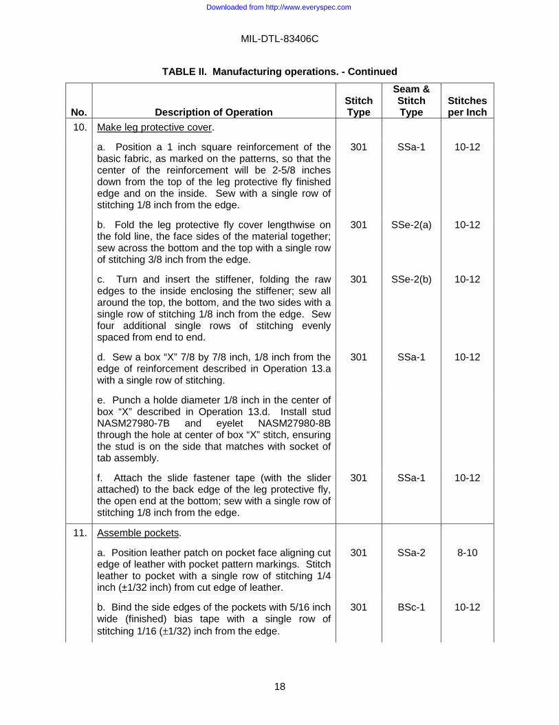
10. Make leg protective cover.
a. Position a 1 inch square reinforcement of the basic fabric, as marked on the patterns, so that the center of the reinforcement will be 2-5/8 inches down from the top of the leg protective fly finished edge and on the inside. Sew with a single row of stitching 1/8 inch from the edge.
301 SSa-1 10-12
b. Fold the leg protective fly cover lengthwise on the fold line, the face sides of the material together; sew across the bottom and the top with a single row of stitching 3/8 inch from the edge.
301 SSe-2(a) 10-12
c. Turn and insert the stiffener, folding the raw edges to the inside enclosing the stiffener; sew all around the top, the bottom, and the two sides with a single row of stitching 1/8 inch from the edge. Sew four additional single rows of stitching evenly spaced from end to end.
301 SSe-2(b) 10-12
d. Sew a box “X” 7/8 by 7/8 inch, 1/8 inch from the edge of reinforcement described in Operation 13.a with a single row of stitching.
301 SSa-1 10-12
e. Punch a holde diameter 1/8 inch in the center of box “X” described in Operation 13.d. Install stud NASM27980-7B and eyelet NASM27980-8B through the hole at center of box “X” stitch, ensuring the stud is on the side that matches with socket of tab assembly.
f. Attach the slide fastener tape (with the slider attached) to the back edge of the leg protective fly, the open end at the bottom; sew with a single row of stitching 1/8 inch from the edge.
301 SSa-1 10-12
11. Assemble pockets.
a. Position leather patch on pocket face aligning cut edge of leather with pocket pattern markings. Stitch leather to pocket with a single row of stitching 1/4 inch (±1/32 inch) from cut edge of leather.
301 SSa-2 8-10
b. Bind the side edges of the pockets with 5/16 inch wide (finished) bias tape with a single row of stitching 1/16 (±1/32) inch from the edge.
301 BSc-1 10-12
Downloaded from http://www.everyspec.com

MIL-DTL-83406C
19
TABLE II. Manufacturing operations. - Continued
No.
Description of Operation
Stitch Type
Seam & Stitch Type
Stitches per Inch
11. Assemble pockets – contd.
c. Place the slide fastener at the marked location on the pocket to the inside; join with a single row of stitching 1/16 inch from the edge all around. (The bridge end shall be at the lowest point on the pocket opening.)
301 SSa-1 10-12
d. Slit through the center and diagonally at the ends. Turn the fabric under approximately 1/4 inch; sew with a single row of stitching 1/16 inch from the folded edge.
301 LSd-1 10-12
e. Sew the bottom corners, the face sides of the material together, with a single row of stitching 3/8 inch from the edge.
301 SSa-1 10-12
f. Raise the sides and the bottom edge of the pockets, at the pattern marks, with a single row of stitching 1/16 inch from the folded edge.
301 OSf-1 10-12
g. Thread a 5-inch length of the 5/16 inch wide webbing for the pull thong through the pull of each slide fastener. Fold the webbing in the center and bartack at the ends and close to the pulls.
bartack 21-23 stitches
per bartack
h. Cut four, 2-3/4-inch squares of the basic fabric to reinforce the slide fasteners. Turn the outside edges of each reinforcement under 1/4 inch on all four sides and stitch two reinforcements to each pocket with a box “X” stitch inside a box through all thicknesses of leather, fabric, and zipper tape. The reinforcements shall be positioned so that a reinforcement will be adjacent to each end of the metal portion of the slide fastener (centered from the top and the bottom on the inside of the pocket).
301 LSa-1 10-12
12. Make leg loop tab assembly.
Cut two pieces of nylon tape in accordance with the patterns, fold at the center, sew a box “X” 3/4 by 1-1/4 inches, 1/8 inch from the folded edge. Punch a hole diameter 1/8 inch in the center of box “X” stitch, install button NASM27980-1B and socket NASM27980-6B through the hole at center of box “X” stitch.
301 SSa-1 10-12
Downloaded from http://www.everyspec.com
MIL-DTL-83406C
20
TABLE II. Manufacturing operations. - Continued
No.
Description of Operation
Stitch Type
Seam & Stitch Type
Stitches per Inch
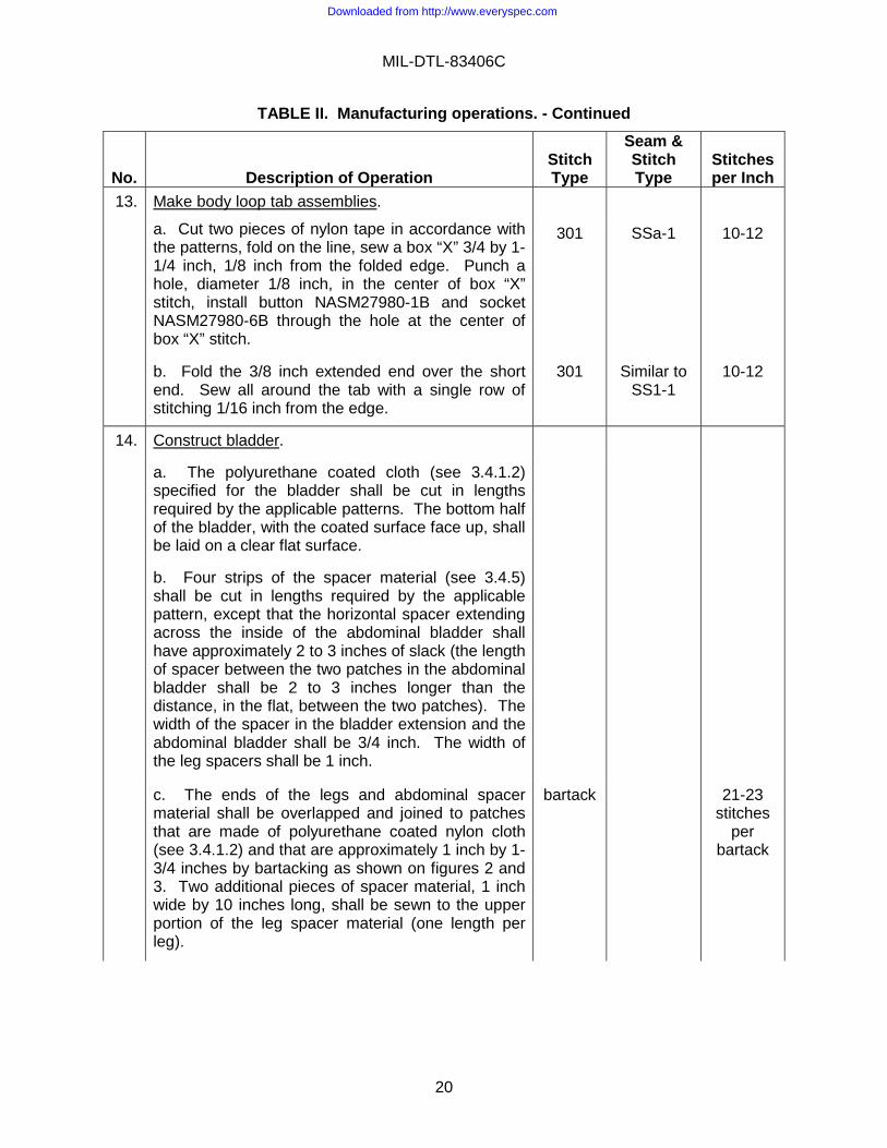
13. Make body loop tab assemblies.
a. Cut two pieces of nylon tape in accordance with the patterns, fold on the line, sew a box “X” 3/4 by 1-1/4 inch, 1/8 inch from the folded edge. Punch a hole, diameter 1/8 inch, in the center of box “X” stitch, install button NASM27980-1B and socket NASM27980-6B through the hole at the center of box “X” stitch.
301 SSa-1 10-12
b. Fold the 3/8 inch extended end over the short end. Sew all around the tab with a single row of stitching 1/16 inch from the edge.
301 Similar to SS1-1
10-12
14. Construct bladder.
a. The polyurethane coated cloth (see 3.4.1.2) specified for the bladder shall be cut in lengths required by the applicable patterns. The bottom half of the bladder, with the coated surface face up, shall be laid on a clear flat surface.
b. Four strips of the spacer material (see 3.4.5) shall be cut in lengths required by the applicable pattern, except that the horizontal spacer extending across the inside of the abdominal bladder shall have approximately 2 to 3 inches of slack (the length of spacer between the two patches in the abdominal bladder shall be 2 to 3 inches longer than the distance, in the flat, between the two patches). The width of the spacer in the bladder extension and the abdominal bladder shall be 3/4 inch. The width of the leg spacers shall be 1 inch.
c. The ends of the legs and abdominal spacer material shall be overlapped and joined to patches that are made of polyurethane coated nylon cloth (see 3.4.1.2) and that are approximately 1 inch by 1-3/4 inches by bartacking as shown on figures 2 and 3. Two additional pieces of spacer material, 1 inch wide by 10 inches long, shall be sewn to the upper portion of the leg spacer material (one length per leg).
bartack 21-23 stitches
per bartack
Downloaded from http://www.everyspec.com

MIL-DTL-83406C
21
TABLE II. Manufacturing operations. - Continued
No.
Description of Operation
Stitch Type
Seam & Stitch Type
Stitches per Inch
14. Construct bladder – contd.
d. The upper end of the piece of spacer material that is 1 inch by 10 inches shall be placed approximately 1 inch below the patch joining the leg spacer to the abdominal spacer and shall be sewn to the leg spacer with two rows of stitching 1/4 inch from each edge of the leg spacer with the thread specified (see 3.4.11) and all ends backstitched a minimum of 1 inch. The bladder extension spacer material shall be overlapped on the abdominal spacer material approximately 2-1/2 inches from the joint between the leg and abdominal spacer material and shall be similarly bartacked (no patch).
301 LSa-2 6-8
e. The spacer material (anti-block system) shall be positioned on the coated side of the bottom half of the bladder as indicated on the applicable pattern and then secured by cementing patches to the bottom of the bladder as shown on figure 1.
f. The bladder halves shall be positioned and RF welded together so that the bonded area will be 1/8 (±1/32) inch wide and the distance from the edge of the bladder to the outside edge of the bond will be 3/8 (±1/16) inch. The bonded seam shall be straight, continuous, and parallel to the edge of the bladder.
15. Hem body bladder cover.
a. Hem the upper edge of the separate leg extension to the inside, 1/4 inch, with a single row of stitching 1/16 inch from the edge.
301 EFa-1 10-12
b. Fold the end of the outside body bladder cover leg, to which the separate leg extension is to be attached, to the inside 1/4 inch and hem with a single row of stitching 1/16 inch from the edge.
301 EFa-1 10-12
Downloaded from http://www.everyspec.com

MIL-DTL-83406C
22
TABLE II. Manufacturing operations. - Continued
No.
Description of Operation
Stitch Type
Seam & Stitch Type
Stitches per Inch
15. Hem body bladder cover - contd.
NOTE: The terms “back body bladder cover,” “front body bladder case,” “outside cover,” and “forward cover” as indicated in this document and on the pattern drawings of the bladder cover shall be interpreted as that portion of the bladder cover on the outside (away from the wearer’s body) and has a truncated section cut off. The term “back body bladder cover” or “front body bladder case” shall be interpreted as the cover positioned next to the wearer’s body and is full size as indicated on the pattern drawings.
c. Lap the hemmed end of the separate leg extension up under the body bladder cover leg end until the lower edge is even with the opposite leg end and sew at the sides with a single row of stitches 1/8 inch from the edge.
301 SSa-1 10-12
16. Join bladder case.
a. Join the front and the back body bladder case, material face to face, with a single row of stitching 1/4 inch from the edge, leaving the legs, the bladder inflation sleeve, and one inch at tab locations (top, bottom, and right side) open.
301 SSe-2(a) 10-12
b. Turn and topstitch with a single row of stitching 1/16 inch from the edge.
301 SSe-2(b) 10-12
17. Hem leg bladder covers.
Hem the leg bladder covers to the inside, 1/4 inch, down the sides and around the bottom and the top, with a single row of stitching 1/16 inch from the edge.
301 EFa-1 10-12
18. Make body section.
a. Join the left side of the body front to the left side of the body back with a double row of stitching, 1/16 inch from the edges, ¼ inch gage.
301 (see figure 4)
10-12
Downloaded from http://www.everyspec.com

MIL-DTL-83406C
23
TABLE II. Manufacturing operations. - Continued
No.
Description of Operation
Stitch Type
Seam & Stitch Type
Stitches per Inch
18. Make body section - contd.
b. Sew a 1-1/8 inch wide bias-cut piece of the basic fabric over the center of the body front and back body seam (inside) with a single row of stitching, 1/16 inch from the edge, each side of the binding.
301 LSd-1 8-10
c. Center the bias-cut pieces of the basic fabric on the stiffeners. Sew three rows of stitching from end to end with one row in the center and one row on the right and the left sides of the center stitching 1/8 inch.
301 SSa-1 10-12
d. Place the stiffeners at the pattern marks on the back body and front body and stitch a single row of stitching, 1/16 inch from the edges, each side of the binding.
301 LSa-1 10-12
e. Place the four lacer loop tapes on the body back, in accordance with the pattern marks, the ends even with the top and bottom edges of the body back, loops facing loops, and join with a double row of stitching 1/16 inch from the edge 3/16 inch gage.
301 SSa-2 10-12
f. Place the pile fastener tape on the lacer loop tape on the body back, 1/8 inch from the loops, and join with a single row of stitching 1/16 inch from the edge.
301 SSa-1 10-12
g. Bind across the top, catching the seam tape and the lacer loop tape in the binding, with the 5/16 inch wide (finished) bias binding with a single row of stitching 1/16 (±1/32) inch from the edge
301 BSc-1 10-12
h. Bind across the bottom of the body front and body back with a 5/16 inch wide (finished) bias tape with a single row of stitching 1/16 (±1/32) inch from the edge.
301 BSc-1 10-12
Downloaded from http://www.everyspec.com

MIL-DTL-83406C
24
TABLE II. Manufacturing operations. - Continued
No.
Description of Operation
Stitch Type
Seam & Stitch Type
Stitches per Inch
18. Make body section - contd.
i. Place a blank label (5 inches long by 1-1/2 inches wide) vertically and approximately centered on the inside, center back section between stiffeners. Sew label to back section with a single row of stitching 1/8 (±1/16) inch from the edge on all four sides.
301 SSa-1 10-12
j. Cut a 4 inch length of the 5/16 inch wide webbing. Bartack one end 3/4 inch down from the top of the edge binding-on-binding strip over the seam joining the body front to the side back. Fold the webbing to the inside; bartack the other end 1-3/4 inches from the top edge binding.
bartack 21-23 stitches
per bartack
k Turn the body lacer cover under 3/8 inch. Place the finished edge of the body lacer cover on the inner row of lacer loop tape, edge to edge; join with a double row of stitching 1/16 inch from the edge, 3/16 inch gage.
301 LSa-2 10-12
19. Attach inflation tube opening reinforcement.
a. Lay the 3-5/16 inch square reinforcement piece of the basic fabric at the marked location on the outside of the body front, evenly spaced over the hole position. Sew around the hole marking, approximately 1-1/8 inch diameter, with a single row of stitching.
301 SSe-2(a) 10-12
b. Trim the 1/4 inch inside stitching and make approximately six small cuts around the edge of the hole but not closer than 1/16 inch from the stitching. Turn the reinforcement piece through the opening; topstitch with a single row of stitching 1/16 inch from the topstitched edge.
301 SSe-2(b) 10-12
c. Turn the outside edge of the reinforcement under ½ inch all around and sew to the body front with a single row of stitching 1/16 inch from the folded edge.
301 LSd-1 10-12
d. Lay the octagon-shaped leather reinforcement piece evenly spaced over the hole position, on the inside of the body front, and sew around the hole 3/32 inch from the edge (on the inside). Sew around the outside edge of the leather patch 3/32 inch from the edge (on the inside).
301 Lsa-2 9-11
Downloaded from http://www.everyspec.com
MIL-DTL-83406C
25
TABLE II. Manufacturing operations. - Continued
No.
Description of Operation
Stitch Type
Seam & Stitch Type
Stitches per Inch
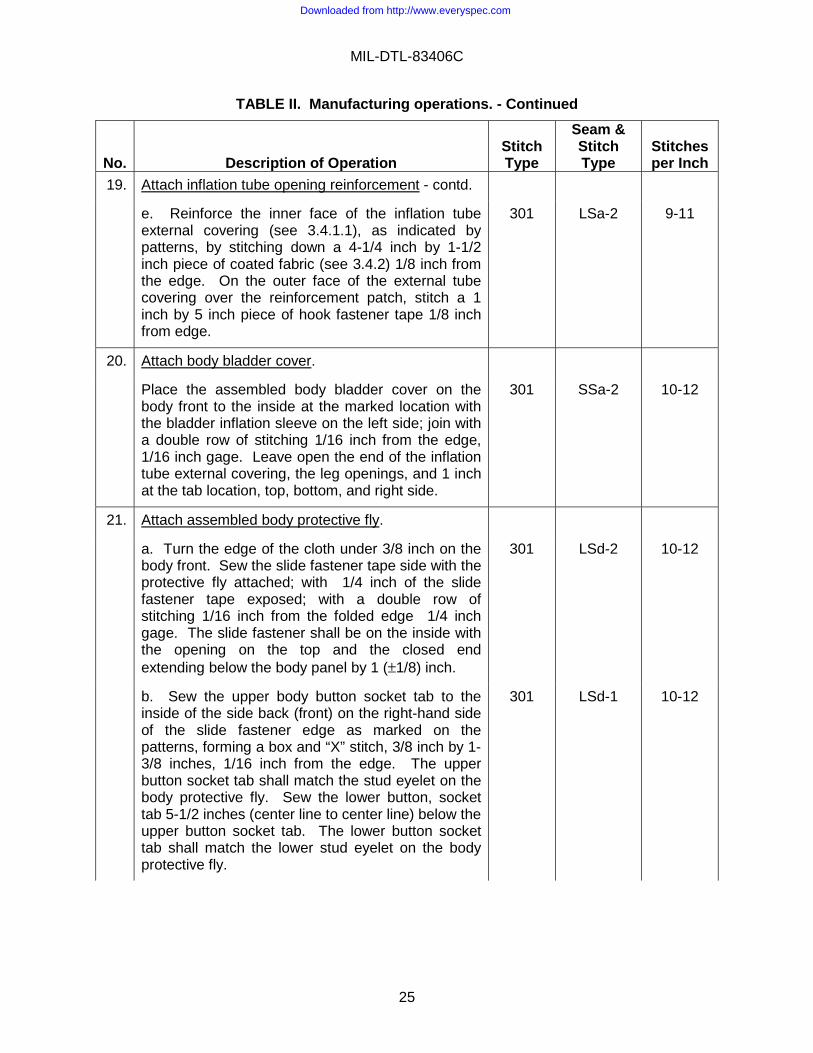
19. Attach inflation tube opening reinforcement - contd.
e. Reinforce the inner face of the inflation tube external covering (see 3.4.1.1), as indicated by patterns, by stitching down a 4-1/4 inch by 1-1/2 inch piece of coated fabric (see 3.4.2) 1/8 inch from the edge. On the outer face of the external tube covering over the reinforcement patch, stitch a 1 inch by 5 inch piece of hook fastener tape 1/8 inch from edge.
301 LSa-2 9-11
20. Attach body bladder cover.
Place the assembled body bladder cover on the body front to the inside at the marked location with the bladder inflation sleeve on the left side; join with a double row of stitching 1/16 inch from the edge, 1/16 inch gage. Leave open the end of the inflation tube external covering, the leg openings, and 1 inch at the tab location, top, bottom, and right side.
301 SSa-2 10-12
21. Attach assembled body protective fly.
a. Turn the edge of the cloth under 3/8 inch on the body front. Sew the slide fastener tape side with the protective fly attached; with 1/4 inch of the slide fastener tape exposed; with a double row of stitching 1/16 inch from the folded edge 1/4 inch gage. The slide fastener shall be on the inside with the opening on the top and the closed end extending below the body panel by 1 (±1/8) inch.
301 LSd-2 10-12
b. Sew the upper body button socket tab to the inside of the side back (front) on the right-hand side of the slide fastener edge as marked on the patterns, forming a box and “X” stitch, 3/8 inch by 1-3/8 inches, 1/16 inch from the edge. The upper button socket tab shall match the stud eyelet on the body protective fly. Sew the lower button, socket tab 5-1/2 inches (center line to center line) below the upper button socket tab. The lower button socket tab shall match the lower stud eyelet on the body protective fly.
301 LSd-1 10-12
Downloaded from http://www.everyspec.com

MIL-DTL-83406C
26
TABLE II. Manufacturing operations. - Continued
No.
Description of Operation
Stitch Type
Seam & Stitch Type
Stitches per Inch
22. Make leg sections.
a. Sew a 5/8 inch wide, bias cut piece of the basic fabric on the inside of the legs, at the positions marked at the sides of the pocket and at the leg take-ups, with a single row of stitching 1/16 inch from the edge each side of the binding, right and left.
301 LSd-1 10-12
b. Turn the neck of the pockets inside 1/4 inch; sew across the knees at the marked locations with a double row of stitching 1/16 inch from the edge, 1/16 inch gage, leaving 1/2 inch at each edge open, the pocket to the outside, the slide fastener closing to the outside.
301 LSd-2 10-12
c. Sew a 2-1/2 inches wide, 4-1/2 inches long reinforcement, made of the bladder material, on the inside of the left leg at the position marked for the pile fastener tape, with a single row of stitching 1/8 inch from the edge.
301 LSa-1 10-12
d. Sew the pile fastener tape on the outside of the left leg, at the marked position, with a single row of stitching 1/8 inch from the edge on all four sides.
301 SSa-1 10-12
e. Place the webbing, with the button socket assembly (NASM27980-1B, -6B) attached to the webbing, on the inside of the legs. The top edge of the webbing shall be parallel with and down from the top, 1-3/4 inches. Sew across the back end of the webbing, following the contour of the bladder cover locations, with a single row of stitching. The socket of the button socket tab shall face the body and shall match the stud on the leg protective fly.
301 LSd-1 10-12
23. Make and attach knife pocket.
a. Lay the knife pocket reinforcement piece on the pocket fabric, face up, in accordance with the notches and the drill marks. Sew the knife pocket reinforcement piece to the pocket with a single row of stitching 1/16 to 1/8 inch from the edge on all four sides.
301 SSa-1 10-12
Downloaded from http://www.everyspec.com

MIL-DTL-83406C
27
TABLE II. Manufacturing operations. – Continued
No.
Description of Operation
Stitch Type
Seam & Stitch Type
Stitches per Inch
23. Make and attach knife pocket - contd.
b. Fold the pocket fabric lengthwise with the raw edges even. Bind the square end with a 5/16 inch wide (finished) bias binding with a single row of stitching 1/16 (±1/32) from the edge. The knife pocket reinforcement shall be on the outside after folding.
301 BSc-1 10-12
c. Bind the straight edge of the small flap reinforcement piece for the top of the pocket with 5/16 inch wide (finished) bias binding with a single row of stitching 1/16 (±1/32) inch from the edge.
301 BSc-1 10-12
d. Position the flap reinforcement piece in accordance with the notch and the drill marks at the round end of the pocket with the flap piece on the same side as the webbing piece. Sew the flap piece to the two top plies of the pocket fabric with a single row of stitching 1/8 (±1/16) inch from the edge. Place the leather reinforcement piece on the outside of the knife pocket, flat and smooth, with the bottom edge resting on the center notch on the knife pocket and the top edge toward the round end of the knife pocket. Stitch the leather reinforcement piece 1/8 (±1/16) inch from the edge on all four sides. Double stitch across the top of the leather reinforcement piece with 1/4-inch gage.
301 SSa-1 10-12
e. Fold the pocket fabric on the center notch. Bind the pocket with 5/16 inch wide (finished) bias binding starting at the bottom folded end and sewing the binding around the sides and the top with a single row of stitching 1/16 (±1/32) inch from the edge. The leather reinforcement piece shall be on the outside after binding. The tape shall extend 1/2 inch beyond the end on each side for turning under.
301 BSc-1 10-12
f. Place a single row of stitching across the flap through both plies at the round end of the flap, approximately 1 inch from the open bound end.
301 SSa-1 10-12
Downloaded from http://www.everyspec.com

MIL-DTL-83406C
28
TABLE II. Manufacturing operations. - Continued
No.
Description of Operation
Stitch Type
Seam & Stitch Type
Stitches per Inch
23. Make and attach knife pocket - contd.
g. Install a size 00 grommet on the pocket, between the square end and the round end of the flap reinforcement piece, in accordance with the drill marks.
h. Position the reinforcement patch on the left thigh front so that the knife pocket is just inside the bladder case stitch line at the front, bottom, and top corners and so that the side of the pocket is parallel to the leg opening slide fastener. Turn the raw edges under 3/8 inch at the bottom and the sides; join with a double row of stitching 1/16 inch from the folded edge 1/4-inch gage. Trim the top even with the top of the thigh.
301 LSd-2 10-12
i. Position the knife pocket on the reinforcement patch, with the round end up and the opening on the inside, in accordance with the drill marks. Start at the bound opening and sew down the side, across the bottom, and up to the bound opening, turning the bias end of the tape under on each side and backstitching 1/2 inch on each side, with a double row of stitching 1/16 inch from the edge, 1/8 inch gage. The distance between the inside longitudinal stitch lines shall be 2-1/4 (±1/8) inches.
301 LSd-2 10-12
j. Sew across the bound square end at the top of the pocket opening, securely tacking the top of the pocket to the patch and the anti-g garment with a single row of stitching.
301 SSa-1 10-12
k. Stamp one snap fastener socket and button to the center of the flap so that the dot on the snap fastener will be at the top of the flap in accordance with the drill marks at the rounded end.
l. Stamp one snap fastener stud and eyelet, reinforced with bladder material on the inside, in the anti-g garment to correspond to the snap fastener socket. If the stud and eyelet location is on top of the binding around the thigh opening, relocate position just below the binding.
Downloaded from http://www.everyspec.com

MIL-DTL-83406C
29
TABLE II. Manufacturing operations. - Continued
No.
Description of Operation
Stitch Type
Seam & Stitch Type
Stitches per Inch
23. Make and attach knife pocket - contd.
m. Thread a 64-inch long lanyard through the grommet. Tie the lanyard with a square knot. Sear both ends of the lanyard. Fold the lanyard in layers that are approximately 4 inches long. Position the folded lanyard in the pocket, parallel with the pocket, with all of the folds within the pocket. Close the snap fastener.
n. Sew the pile fastener tape for the checklist fastener to the outside of the left leg, at the location shown on figure 5 with a single row of stitching 1/8 inch from the edge on all four sides.
301 SSa-1 10-12
o. Using figure 5 as a guide, sew the pile fastener tape for the checklist fastener to the right leg with a single row of stitching 1/8 inch from the edge of all four sides.
301 SSa-1 10-12
24. Attach leg bladder covers.
Place the leg bladder covers on the legs at the marked locations on the patterns. Join down each side, leaving the top and 1 inch at the marked position for the tabs open, with a double row of stitching 1/16 inch from the edge, 1/16-inch gage. Fold back 1/4 inch at the neck of the pocket left loose so that the pocket is not stitched through in this operation.
301 LSd-2 10-12
25. Attach pockets.
a. Sew the pockets to the lower legs on the center of the basic fabric bias binding, down each side, with a single row of stitching 1/16 inch from the edge of the pocket binding.
301 LSd-1 10-12
b. Join the pockets at the bottom and the upper edges at the knee opening to the legs with a single row of stitching 1/8 inch from the edge.
301 SSa-1 10-12
Downloaded from http://www.everyspec.com
MIL-DTL-83406C
30
TABLE II. Manufacturing operations. - Continued
No.
Description of Operation
Stitch Type
Seam & Stitch Type
Stitches per Inch
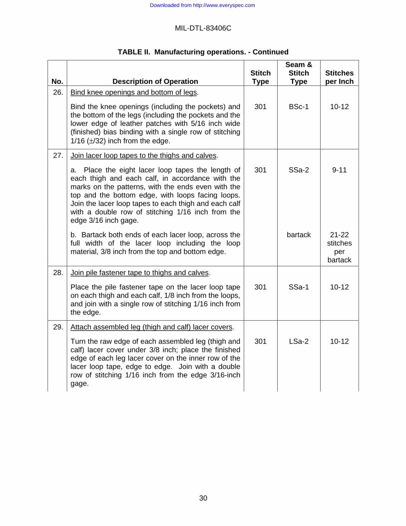
26. Bind knee openings and bottom of legs.
Bind the knee openings (including the pockets) and the bottom of the legs (including the pockets and the lower edge of leather patches with 5/16 inch wide (finished) bias binding with a single row of stitching 1/16 (±/32) inch from the edge.
301 BSc-1 10-12
27. Join lacer loop tapes to the thighs and calves.
a. Place the eight lacer loop tapes the length of each thigh and each calf, in accordance with the marks on the patterns, with the ends even with the top and the bottom edge, with loops facing loops. Join the lacer loop tapes to each thigh and each calf with a double row of stitching 1/16 inch from the edge 3/16 inch gage.
301 SSa-2 9-11
b. Bartack both ends of each lacer loop, across the full width of the lacer loop including the loop material, 3/8 inch from the top and bottom edge.
bartack 21-22 stitches
per bartack
28. Join pile fastener tape to thighs and calves.
Place the pile fastener tape on the lacer loop tape on each thigh and each calf, 1/8 inch from the loops, and join with a single row of stitching 1/16 inch from the edge.
301 SSa-1 10-12
29. Attach assembled leg (thigh and calf) lacer covers.
Turn the raw edge of each assembled leg (thigh and calf) lacer cover under 3/8 inch; place the finished edge of each leg lacer cover on the inner row of the lacer loop tape, edge to edge. Join with a double row of stitching 1/16 inch from the edge 3/16-inch gage.
301 LSa-2 10-12
Downloaded from http://www.everyspec.com

MIL-DTL-83406C
31
TABLE II. Manufacturing operations. - Continued
No.
Description of Operation
Stitch Type
Seam & Stitch Type
Stitches per Inch
30. Join leg take-ups.
Position one end of the kneeboard elastic subassembly (face up) under the thigh take-up assembly in accordance with pattern markings. Join the assembled right and left take-ups to the outside at the thigh, in accordance with the pattern marks, down the sides and across the top with a double row of stitching, 1/16 inch from the edge, 3/16-inch gage. The slide fasteners shall close at the top.
301 LSa-2 10-12
NOTE: Use proper thread tension and fabric tension to avoid waviness (chain flatness of slide fastener).
31. Sew around reinforcement.
Sew around the edges of the reinforcement inside of the leg take-ups with a single row of stitching, 1/16 inch from the edge.
301 SSa-1 10-12
32. Attach assembled leg protective flies.
Position the remaining end of the kneeboard elastic subassembly (face-up) on the leg section in accordance with pattern markings. Turn the edge of the cloth and elastic subassembly under 3/8 inch. Place the edge of the cloth down the legs on the slide fastener tapes so that the separating ends of the slide fastener will be at the top, the protective fly will open to the back, the corners at the knee holes will be spaced 3/4 (±1/8) inch apart on the slide fastener tapes, and 1/4 inch of the slide fastener tape will be exposed. Join with a double row of stitching 1/16 inch from the edge, 1/4-inch gage.
301 LSd-2 10-12
33. Install snap fasteners.
a. Install the snap fastener cap and socket through the lower edge of the legs to the side opposite the protective fly, 7/8 inch from the bottom edge and 5/8 inch from the edge of the slide fastener teeth edge to the center of the snap fastener, with the cap on the face side of the cloth.
Downloaded from http://www.everyspec.com

MIL-DTL-83406C
32
TABLE II. Manufacturing operations. - Continued
No.
Description of Operation
Stitch Type
Seam & Stitch Type
Stitches per Inch
33. Install snap fasteners - contd.
b. Install the snap fastener stud and post, to match the snap fastener cap and socket, through the protective flies at the bottom of the legs, approximately 5/8 inch from the edge of the protective fly and 1 inch up from the bottom edge of the legs to the center of the snap fasteners with the stud to the outside.
34. Join upper ends of legs to body front.
a. Join the upper ends of the legs to the body front, with the face sides of the material together, in accordance with the marks on the patterns, with a single row of stitching 3/8 inch from the edge.
301 LSq-2(a) 10-12
b. Turn and topstitch with a single row of stitching 1/16 inch from the folded edge.
301 LSq-2(b) 10-12
c. Sew an additional row of stitching 5/16 inch from the folded edge.
301 SSa-1 10-12
35. Insert adjustment laces in take-ups.
a. Select the adjustment laces in accordance with table IV.
b. Insert the adjustment laces into the lacer loops for the body take-ups as follows: Start lacing from the bottom, similar to lacing shoes. Route the adjustment laces through each lacer loop on each side (loose ends exiting from the top lacer loops). Draw the lacing up so that approximately one-half of the adjustment will be taken with the lacing. Fold the excess lacing into a hank that is approximately 3 inches long. Wrap the hank with one turn of 2-inch wide tape that conforms to SAE-AMS-T-22085.
Downloaded from http://www.everyspec.com

MIL-DTL-83406C
33
TABLE II. Manufacturing operations. - Continued
No.
Description of Operation
Stitch Type
Seam & Stitch Type
Stitches per Inch
36. Insert adjustment laces in take-ups - contd.
c. Insert the adjustment laces into the lacer loops for the thigh take-ups in the same manner as specified for the body take-ups in Operation 35.b, except that the lacing shall start from the top lacer loops and exit from the bottom lacer loops. Draw the lacing up so that approximately one-half of the adjustment will be taken up with the lacing. Fold the excess lacing into a hank that is approximately 3 inches long. Wrap the hank with one turn of 2 inch wide tape that conforms to SAE-AMS-T-22085.
d. Insert the adjustment laces into the lacer loops for the calf take-ups in the same manner as specified for the body take-ups in Operation 35.b, except that the lacing shall be pulled tight (minimum ankle circumference shall be 12 inches for all sizes except that the minimum ankle circumference for the size large extra long shall be 13-3/4 inches).
37. Final assembly.
Install the bladder through the openings at the top of the legs left open for this purpose and into the bladder covers. Insert the bladder tabs through the 1 inch wide openings; sew with a double row of stitching 1/16 inch from the edge, 1/16 inch gauge.
301 SSa-2 10-12
38. Make connector assembly.
See section U-U of figure 1. Insert the free end of the rubber sleeve (see 3.4.17), the unfolded end of the mesh spacer tube (section B-B of Drawing 74204), and insert interlaced springs (see 3.4.20) over the spacer tube so that it ends about 1/4 inch from the wide labeled part of the connector. Connect the spacer tube and spacer fabric to the rubber sleeve by clamping in place with NAS397-14 about one inch from the wide labeled part of the connector. Wrap the clamped area with at least two full turns of the wrapping tape. Clamped areas shall be centered within at least 1 inch width of the wrapping tape.
301 SSa-2 10-12
Downloaded from http://www.everyspec.com

MIL-DTL-83406C
34
TABLE II. Manufacturing operations. - Continued
No.
Description of Operation
Stitch Type
Seam & Stitch Type
Stitches per Inch
39. Attach connector assembly to inflation tube.
a. Make an insertion tool from a coat hanger or any other suitable wire by clipping and filing the end round and smooth.
b. Insert the insertion tool into the folded end of the spacer tube (see A-A of AF Drawing 74204). Push the spacer assembly into the fladder inflation hose, working the spacer tube in slowly so that it lies adjacent to the existing Trilok spacer and so that the spacer extends approximately 4 inches into the body bladder. When the spacer tube is completely inserted, hold on to the folded end of the spacer tube from the outside of the body bladder and pull the insertion tool out.
c. See section U-U of figure 1. Pull the bladder inflation tube over the spacer tube assembly and rubber sleeve flush with the wide labeled part of the connector. Clamp the bladder inflation tube to the rubber sleeve of the connector assembly with NAS397-16 (see Operation 37) clamp toward the conncecor and wrap the clamped area with at least two full turns of wrapping tape. Clamped areas shall be centered within at least a one inch width of wrapping tape.
d. See section U-U of figure 1. Install the rubber band (see 3.4.22) over all wrapped, clamped areas so that about a third of the rubber band covers the wide labeled part of the connector and the rest covers the wrapped clamped areas. All wrapping tape shall be covered by the rubber band.
FIGURE 4. Seam type.
Downloaded from http://www.everyspec.com

MIL-DTL-83406C
35
FIGURE 5. Location of checklist fastener.
Downloaded from http://www.everyspec.com

MIL-DTL-83406C
36
TABLE III. Dimensions of hook and pile fastener tape (inches).
Size of Anti-g Garment
Body Lacer Covers
1/ 2/
Thigh Lacer Covers
1/ 2/
Checklist Retainers
3/
Calf Lacer Covers
1/ 2/
Small regular (SR) 1 x 9-1/2 1 x 10⁻⁵/8 2 x 4 1 x 12-1/2
Small long (SL) 1 x 9-1/2 1 x 11-1/2 2 x 4 1 x 13-18
Medium regular (MR) 1 x 10 1 x 10⁻⁷/8 2 x 4 1 x 12-1/2
Medium long (ML) 1 x 10 1 x 11-3/8 2 x 4 1 x 13-1/8
Large regular (LR) 1 x 10 1 x 10⁻⁷/8 2 x 4 1 x 12-1/2
Large long (LL) 1 x 10 1 x 11-1/4 2 x 4 1 x 13-1/4
Large extra long (LXL) 1 x 10 1 x 11-1/4 2 x 4 1 x 17-1/4
NOTES: 1/ Since the requirements of table II specify that the fastener tape for the lacer covers shall be trimmed, if necessary, so that the fastener tape will be even with the top and the bottom edges of the flap, these dimensions are approximate. 2/ Two for each anti-g garment shall be required. 3/ Two of the pile fastener tape shall be required.
TABLE IV. Length of adjustment laces (feet). 1/
Size of Anti-g Garment
Body Area 2/
Thigh Area 2/
Calf Area 2/
Small regular (SR) 12 12 14
Small long (SL) 12 13 16
Medium regular (MR) 12 13 16
Medium long (ML) 12 14 17
Large regular (LR) 13 14 17
Large long (LL) 13 16 19
Large extra long (LXL) 13 16 19
NOTES: 1/ The dimensions specified in this table are approximate and shall be governed by the following requirement: Both ends of each adjustment lace shall extend at least six inches beyond the open end of the lacing tape when the adjustment laces are completely extended. Both ends of each adjustment lace shall be dipped in a hot solution of 50% beeswax and 50% paraffin. 2/ Two per anti-g garment shall be required.
Downloaded from http://www.everyspec.com

MIL-DTL-83406C
37
3.7 Performance
3.7.1 Leakage. When the bladder in the anti-g garment is inflated to a pressure of 12 psig, the bladder shall not lose more than 0.5 psig of air pressure in 60 seconds (see 4.5.2).
3.7.2 Endurance. When the anti-g garment is inflated 1,000 times, to a pressure of 15 psig, the anti-g garment shall not develop any structural defects. Structural defects shall include, but not be limited to, material torn, seam separation, slide fastener slider lock broken, slide fastener chain separated, or clamps loosened or broken. After the anti-g garment has been inflated 1,000 times, to a pressure of 15 psig, the anti-g garment shall meet the requirements in Operation 17 (see 4.5.3).
3.7.3 Inflation time. With a free airflow of 10 cubic feet per minute and with a back pressure of 9 to 12 psig applied from the pressure source, the anti-g garment shall inflate to a pressure of 8 psig in not more than 3 seconds (see 4.5.4).
3.7.4 Low temperature storage.
The anti-g garment shall not be adversely affected by storage at a temperature of −60 °F (see 4.5.5).
3.7.5 High temperature storage.
The anti-g garment shall not be adversely affected by storage at a temperature of +160 °F (see 4.5.6).
3.7.6 Low temperature operation.
The anti-g garment shall operate satisfactorily at a temperature of −30 °F (see 4.5.7).
3.7.7 Bond strength (bladder). The force required to separate the bonded bladder halves shall be not less than 40 pounds (see 4.5.8).
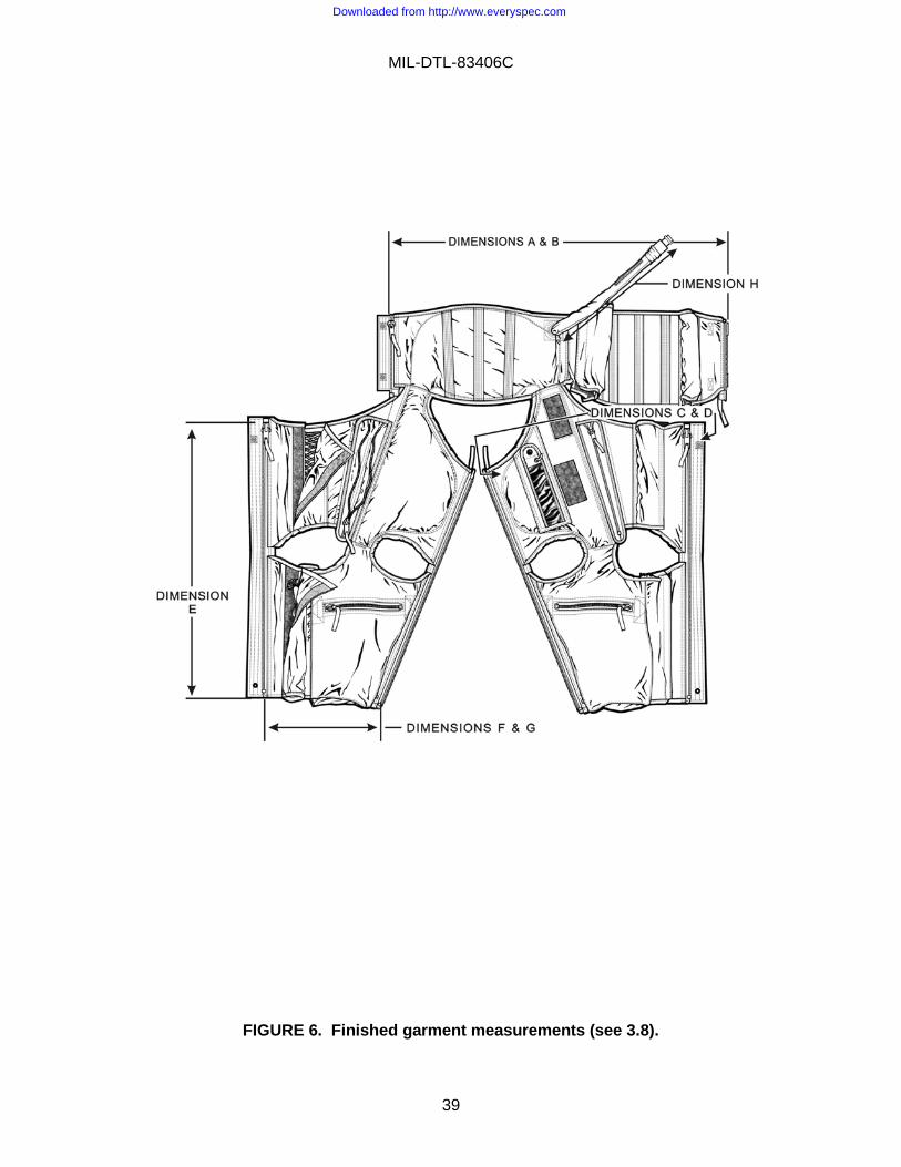
3.8 Finished measurements. The finished measurements of the anti-g garment shall be as specified in table V. The minimum finished measurements specified in table V shall be the measurements of the finished anti-g garment when its adjustment laces are tight. The maximum finished measurements specified in table V shall be the measurements of the finished anti-g garment when its adjustment laces are loose and the fabric is stretched to the limit of the solid fabric with the lacer cover closed. The finished measurements (see figure 6) shall be taken with the body slide fastener and the leg slide fasteners open and as follows: Measure the body circumference straight across the top edge of the body. Measure the thigh circumference, with the thigh take-up slide fasteners closed for the minimum finished measurement and with the thigh take-up slide fastener open for the maximum finished measurement, straight across the top edge of the cut out. Measure the leg length at the slide fastener location from the top to the bottom of the slide fastener of the leg opening. Measure the ankle circumference straight across the leg terminal. Measure the length
Downloaded from http://www.everyspec.com

MIL-DTL-83406C
38
of the inflation tube from the end of the nose piece of the connector (see figure 1 of MIL-C-83390) to the end of the stitching of the bladder cover to the body front at the bladder neck opening (see body front pattern).
TABLE V. Finished measurements (inches) (see figure 6).
Size of Anti-g Garment
Body Circumference
Thigh Circumference
Leg Length
at Fastener Location
Ankle Circumference
Hose Length
A B C D E F G H
Min Max Min Max Nominal Min Max Nominal
Small regular (SR) 29-1/2 34-1/2 21 26 26 12 15 17
Small long (SL) 29 34-1/4 20-3/4 25-1/2 28 12 15 17
Medium regular (MR) 32-1/4 38-1/4 22-1/4 27-1/4 26-1/2 12 15 17
Medium long (ML) 32 38 22-1/2 27-1/2 28-1/2 12 15 17
Large regular (LR) 35-1/4 41 23-1/2 28-3/4 27 12 15 17
Large long (LL) 35-1/2 41-1/4 24 29 29 12 15 17
Large extra long (LXL) 35-1/2 41-1/4 24 29 33 13-3/4 16-3/4 17
Tolerance +3/4 -1/2
+3/4 -1/2
+1/2 -3/8
+1/2 -3/8
±1/2 +0 -1/2
±1/4 ±1/4
3.9 Color. The color of the materials of the anti-g garment shall be as specified herein. Materials for which color requirements have not been specified and which are hidden by the construction may be used in natural or colored form. The color of all exposed sewing threads shall approximately match the color of the basic fabric specified in 3.4.1.1.
Downloaded from http://www.everyspec.com
MIL-DTL-83406C
39
FIGURE 6. Finished garment measurements (see 3.8).
Downloaded from http://www.everyspec.com

MIL-DTL-83406C
40
3.10 Identification of product.
3.10.1 Labels. Each anti-g garment shall have a contractor's label, a size label, an instruction label, and a blank label.
3.10.1.1 Contractor's label. The contractor's label shall conform to type VI, class 1 of MIL-DTL-32075 and shall be approximately 2-1/2 inches by 1-1/2 inches. The label shall contain the following information:
Anti-g Garment, Cutaway, CSU-13B/P Specification 1/ Manufacturer's Identification 1/ Contract or Order No. 1/
1/ The manufacturer shall insert the applicable information.
3.10.1.2 Size label. The size label shall conform to type VI, class 2 of MIL-DTL-32075 and shall be approximately 2-1/2 inches by 1-1/2 inches. In addition to the adjective size, the size label shall contain the stature and the weight ranges (see 6.4), and the stock number of the anti-g garment in the following manner:
Size 1/ Stature 1/ Weight 1/ Stock No. 1/ Lot No. 1/ Serial No. (see 3.10.3) Date of Manufacture 1/ 1/ The manufacturer shall insert the applicable information.
3.10.1.2.1 Stamped size label. The upper tab of the finished bladder shall be stamped for identification with the abbreviated anti-g garment size.
3.10.1.3 Instruction label. The instruction label shall conform to type VI, class 3 of MIL-DTL-32075 and shall be approximately 2-1/2 inches by 1-1/2 inches. The instruction label shall contain the following information:
DO NOT IRON OR DRY CLEAN. PLUG AIR INLET PORT SECURELY. WASH WITH MILD SOAP AND WITH WATER NOT OVER 120 °F.
THE MATERIAL OF THE OUTER SHELL OF THIS ANTI-G GARMENT IS AN INHERENT FIRE RESISTANT MATERIAL THAT WILL NOT MELT OR DRIP AND CAN BE LAUNDERED WITHOUT LOSING ITS FIRE-RESISTANT PROPERTIES. NO RETREATMENT IS NECESSARY.
Downloaded from http://www.everyspec.com

MIL-DTL-83406C
41
3.10.2 Blank label. The blank label shall conform to type VI of MIL-DTL-32075 and shall be approximately 5 inches by 1-1/2 inches.
3.10.3 Serial numbers. The cutaway garment shall be identified by individual serial numbers which shall be assigned by the manufacturer. Serialization shall be by a block of consecutive numbers to cover the entire acquisition document quantity.
3.10.4 Special identification. The abdominal area of each anti-g garment that has been subjected to the endurance test described in 4.5.3 shall be marked, with waterproof ink, in letters that are at least 1 inch high. The marking shall be as follows: ENDURANCE TESTED - NOT TO BE USED IN FLIGHT.
3.11 Patterns. The standard patterns referenced in AF Drawings 71380 through 71386 and AF Drawings 74204 and 74206 will be furnished by the Government (see 6.7). The standard patterns show size, directional lines, and notches for the proper assembly of the parts of the anti-g garment. The standard patterns shall be used by the manufacturer as a guide in cutting the manufacturer’s working patterns. The manufacturer’s working patterns shall be identical in size and shape to the standard patterns. Neither the standard patterns nor the manufacturer’s working patterns shall be altered in any way.
3.11.1 Directional line. A straight line with an arrow at each end and the word “straight” affixed to the straight line marked on a pattern part indicates the straight of the material which is also defined as the warp or lengthwise direction of the cloth or fabric. The pattern part shall be laid on the cloth so that the straight line with the arrows indicating the “straight” of the fabric is parallel to the selvage edge (lengthwise) of the fabric. This shall be accomplished by placing the straight line on the lengthwise grain of the fabric as follows: Measure the distance, at two points, from the straight line to the selvage. Adjust the pattern part until the distance from the straight line to the selvage is the same from both points (see figure 7).
FIGURE 7. Directional line.
Downloaded from http://www.everyspec.com

MIL-DTL-83406C
42
3.12 Workmanship. Inasmuch as the correct functioning of the anti-g garment directly affects the safety of personnel, it shall be free from all defects affecting service or appearance and shall meet or exceed the quality of product established by this specification.
4. VERIFICATION
4.1 Classification of inspection. The inspection requirements specified herein are classified as follows:
a. First article inspection
b. Qualification inspection
c. Conformance inspection.
4.1.1 Atmospheric conditions. Unless otherwise specified herein, all tests required by this specification shall be made at an atmospheric pressure of 28 to 32 inches of mercury, at a temperature of 77 (±18) °F, and at a relative humidity of 80% or less. Where tests are made with atmospheric pressure or temperature substantially different from these values, proper allowance shall be made for the change in instrument reading.
4.1.2 Connector. A connector conforming to MS27755 shall be used to connect the anti-g garment to the air source for tests that require inflation and deflation cycling of the anti-g garment.
4.1.3 Air. The air used to test the anti-g garment as specified herein shall not contain any oil or moisture.
4.1.4 Air pressure gauges. Air pressure gauges utilized shall be in pounds per square inch, digital, and shall be precise and calibrated to at least one hundredth of a psig.
4.2 First article inspection. The first article samples specified in 4.2.1.1 shall be subjected to first article inspection. The first article inspection for the anti-g garment shall consist of the tests described in 4.5.1 through 4.5.7. The first article inspection for the bladder shall consist of the test described in 4.5.8.
4.2.1 First article samples. The first article samples shall be manufactured after the award of the contract and before production of the anti-g garment commences. The first article samples shall consist of the items specified herein and shall be representative of the materials, components, construction, and workmanship to be used in the production items. If a manufacturer is in continuous production of the anti-g garments from contract to contract, inspection and submission of further first article samples may be waived at the discretion of the procuring activity. Approval of the first article
Downloaded from http://www.everyspec.com

MIL-DTL-83406C
43
samples or the waiver of the first article inspection shall not preclude the requirements for the performance of the quality conformance inspection.
4.2.1.1 Untested samples. The manufacturer of the anti-g garments shall subject two anti-g garments and two bladders for each size being made under that contract (see 6.2) for the first article inspection described in 4.2.
4.3 Qualification inspection. The qualification samples described in 4.3.1 shall be subjected to qualification inspection. The qualification inspection for the anti-g garments and bladders shall consist of the test methods described in 4.5.1 through 4.5.7. The qualification inspection for the bladder shall consist of the test described in 4.5.8.
4.3.1 Samples for qualifying activity. Qualification samples, consisting of two anti-g garments tested as specified in 4.4 and of two untested bladders, shall be furnished to the qualifying activity (see 6.6).
4.4 Conformance inspection. Conformance inspection shall consist of the following:
a. Individual inspection
b. Sampling inspection.
4.4.1 Individual inspection. Each anti-g garment shall be subjected to the following tests as described under 4.6:
a. Examination of product
b. Leakage.
4.4.2 Sampling inspection. Sampling inspection shall be conducted in accordance with plans A and B for the end items and components (see 4.4.3.2 and 4.4.3.3).
4.4.3 Plans for end items and components.
4.4.3.1 Lot formation. Each lot for plan A shall consist of 500 anti-g garments that have been manufactured essentially under the same conditions and submitted for inspection at substantially the same time see 4.4.3.2). Each lot for plan B shall consist of 501 bladders that have been manufactured essentially under the same conditions and submitted for inspection at substantially the same time (see 4.4.3.3). A fraction of a lot shall not be permitted for plan A or B unless the total quantity of the anti-g garments required to be delivered during a specified period under the contract is less than 500 anti-g garments.
Downloaded from http://www.everyspec.com

MIL-DTL-83406C
44
4.4.3.2 Plan A. Two anti-g garments shall be selected at random from each lot or fraction thereof, provided a fraction is permitted (see 4.4.3.1). Each anti-g garment selected shall be subjected to the following tests as described under 4.5:
a. Endurance
b. Inflation time.
4.4.3.3 Plan B. One bladder shall be selected at random from each lot of bladders or fraction thereof, (see 4.4.3.1), provided a fraction of a lot is permitted. The bladder selected as a sample shall be subjected to the test described in 4.5.8.
4.4.3.4 Rejection and retest. When one or more items selected from a lot in accordance with plan A or B fail to meet the specification, acceptance of all items in the lot shall be withheld until the extent and cause of the failure have been determined. The contractor shall explain fully, to the Government representative and notify the procuring activity in writing, the cause of failure, the action taken to preclude recurrence, and the impact this failure may have in scheduled deliveries. After correction, all of the sampling tests shall be repeated.
4.4.3.5 Individual tests may continue. For production reasons, individual inspection or other sampling plans may be continued pending the investigation of a sampling test failure. Final acceptance of the entire lot or lots produced later shall not be made until it is determined that all items meet all the requirements of the specification.
4.4.3.6 Defects in items already accepted. The investigation of a test failure could indicate that defects may exist in items already accepted. If so, the contractor shall fully advise the procuring activity of all defects likely to be found and the method of correcting them.
4.5 Test methods
4.5.1 Examination of product. The anti-g garment shall be examined to determine compliance with the requirements of this specification with respect to materials, finished measurements, identification marking, and workmanship. Defects found during this examination shall be classified as specified in table VI. If the anti-g garment contains any major defect, the anti-g garment shall be rejected. If the anti-g garment contains two or more minor defects, the anti-g garment shall be rejected.
Downloaded from http://www.everyspec.com
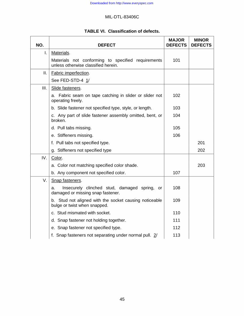
MIL-DTL-83406C
45
TABLE VI. Classification of defects.
NO.
DEFECT
MAJOR DEFECTS
MINOR DEFECTS
I. Materials.
Materials not conforming to specified requirements unless otherwise classified herein.
101
II. Fabric imperfection.
See FED-STD-4 1/
III. Slide fasteners.
a. Fabric seam on tape catching in slider or slider not operating freely.
102
b. Slide fastener not specified type, style, or length. 103
c. Any part of slide fastener assembly omitted, bent, or broken.
104
d. Pull tabs missing. 105
e. Stiffeners missing. 106
f. Pull tabs not specified type. 201
g. Stiffeners not specified type 202
IV. Color.
a. Color not matching specified color shade. 203
b. Any component not specified color. 107
V. Snap fasteners.
a. Insecurely clinched stud, damaged spring, or damaged or missing snap fastener.
108
b. Stud not aligned with the socket causing noticeable bulge or twist when snapped.
109
c. Stud mismated with socket. 110
d. Snap fastener not holding together. 111
e. Snap fastener not specified type. 112
f. Snap fasteners not separating under normal pull. 2/ 113
Downloaded from http://www.everyspec.com
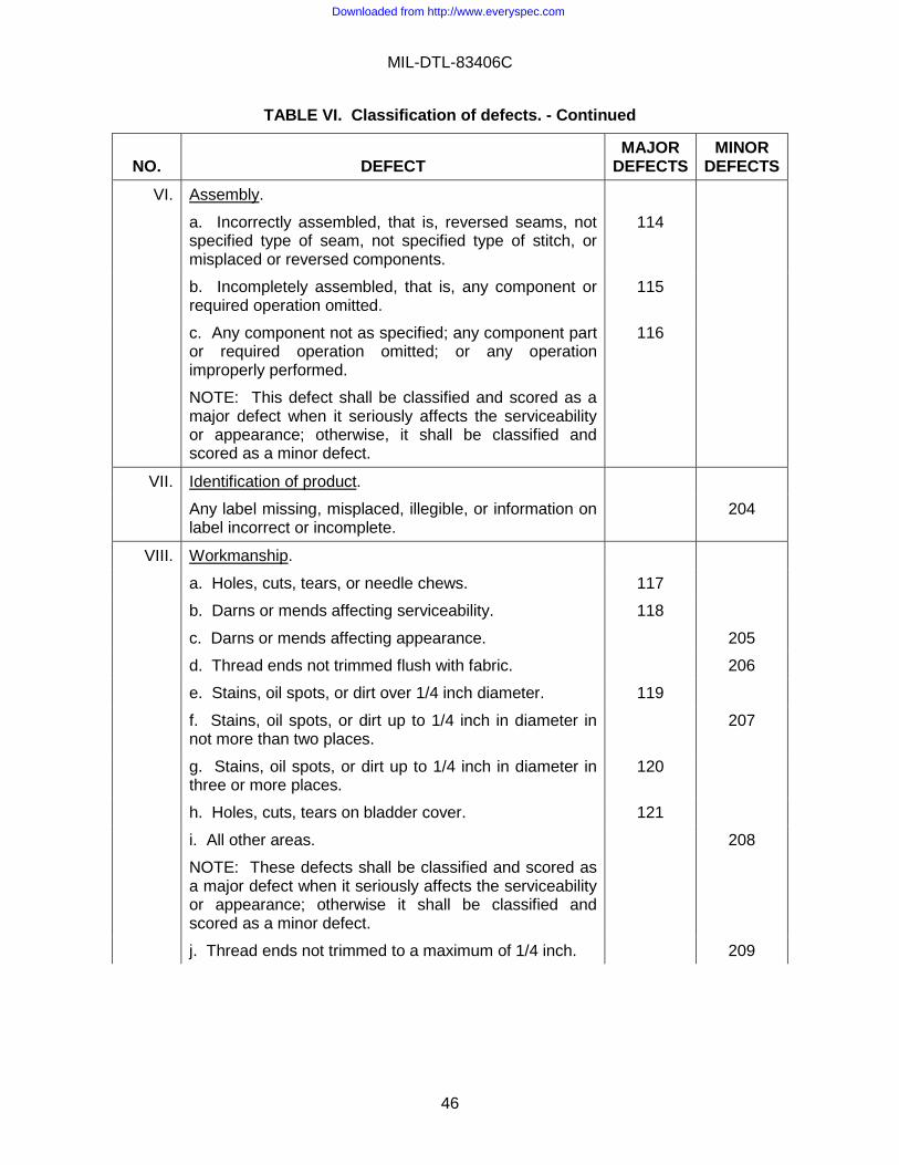
MIL-DTL-83406C
46
TABLE VI. Classification of defects. - Continued
NO.
DEFECT
MAJOR DEFECTS
MINOR DEFECTS
VI. Assembly.
a. Incorrectly assembled, that is, reversed seams, not specified type of seam, not specified type of stitch, or misplaced or reversed components.
114
b. Incompletely assembled, that is, any component or required operation omitted.
115
c. Any component not as specified; any component part or required operation omitted; or any operation improperly performed.
NOTE: This defect shall be classified and scored as a major defect when it seriously affects the serviceability or appearance; otherwise, it shall be classified and scored as a minor defect.
116
VII. Identification of product.
Any label missing, misplaced, illegible, or information on label incorrect or incomplete.
204
VIII. Workmanship.
a. Holes, cuts, tears, or needle chews. 117
b. Darns or mends affecting serviceability. 118
c. Darns or mends affecting appearance. 205
d. Thread ends not trimmed flush with fabric. 206
e. Stains, oil spots, or dirt over 1/4 inch diameter. 119
f. Stains, oil spots, or dirt up to 1/4 inch in diameter in not more than two places.
207
g. Stains, oil spots, or dirt up to 1/4 inch in diameter in three or more places.
120
h. Holes, cuts, tears on bladder cover. 121
i. All other areas.
NOTE: These defects shall be classified and scored as a major defect when it seriously affects the serviceability or appearance; otherwise it shall be classified and scored as a minor defect.
208
j. Thread ends not trimmed to a maximum of 1/4 inch. 209
Downloaded from http://www.everyspec.com

MIL-DTL-83406C
47
TABLE VI. Classification of defects - Continued.
NO.
DEFECT
MAJOR DEFECTS
MINOR DEFECTS
IX. Measurements
a. Any finished measurement not within specified tolerance.
122
b. Distance between inside longitudinal stitch lines, attaching knife pocket to reinforcement patch, greater than 2-3/8 inches or less than 2-1/8 inches.
123
c. Width of inside opening of knife pocket (distance between longitudinal stitch lines) less than 1-3/4 inches).
124
X. Hook assembly.
a. Hook assembly not specified type. 125
b. Hook not aligned with loop (tolerance 1/8 inch) 3/
(1) more than 1/8 inch but less than 1/4 inch 210
(2) more than 1/4 inch 211
XI. Stitches and seams.
a. Open seams shall be defined as one or more broken stitches or two or more continuous skipped stitches or run-offs
(1) one or more broken stitches or two or more skipped stitches on bladder cover and leg and body slide fasteners.
126
(2) all others. 212
b. Ends of stitching not caught in other seams or stitching not securely backstitched for a minimum of 1/2 inch.
127
c. Stitching missing, broken, skipped, or cut. 128
d. Run-offs. 129
e. Stitching margins unless otherwise classified herein: 4/
(1) up to 1/16 inch stitching margins not within tolerance of +1/32 or -0 inch.
130
(2) over 1/16 to 1/4 inch stitching margins (tolerance +1/32 or -0 inch) that exceeds plus tolerance less than +1/16 inch.
213
(3) over 1/16 to 1/4 inch stitching margins (tolerance +1/32 or -1/32 or -0 inch) that exceeds tolerance more than +1/16 or more than -1/32 inch
131
Downloaded from http://www.everyspec.com

MIL-DTL-83406C
48
TABLE VI. Classification of defects - Continued.
NO.
DEFECT
MAJOR DEFECTS
MINOR DEFECTS
XI. Stitches and seams – Contd.
(4) over 1/16 to 1/4 inch stitching margins (tolerance +1/32 inch or -0 inch) that exceeds plus tolerance less than +1/16 inch.
214
(5) over 1/16 inch to 1/4 inch stitching margins (tolerance +1/32 inch or -0 inch) that exceeds tolerance more than +1/16 or more than -1/32 inch.
132
(4) over 1/4 to 1/2 inch stitching margins (tolerance +1/16 or -1/32 inch) that exceeds tolerance by more than +1/16 or more than -1/32 inch.
133
f. Seams not within tolerance of ±1/32 inch:
(1) up to 1/4 inch seam that exceeds tolerance up to +1/32 inch.
215
(2) up to 1/4 inch seams that exceeds tolerance more than ±1/32 inch.
134
(3) over 1/4 inch seams that exceeds tolerance up to +1/16 inch
216
(4) over 1/4 inch seams that exceeds tolerance more than +1/16 or -1/32 inch.
135
g. more than 1/4 inch but less than 1 inch raw edge. 217
h. More than 1 inch raw edge. 136
NOTES:
1/ Fabric imperfections that would affect the function of the anti-g garment shall be considered major defects.
2/ The snap fastener shall be checked for proper function and attachment by snapping closed and unsnapping the snap fastener at least three times.
3/ The hook assembly shall be checked by attaching the hook to the loop and closing the slide fastener. Alignment of the hook assembly shall not interfere with the slide fastener operation.
4/ The classification of defects for stitching margins shall not apply to any stitching margins for which a tolerance has been specified in table II. A stitching margin that is not within the tolerance specified in table II shall be classified as a major defect.
Downloaded from http://www.everyspec.com

MIL-DTL-83406C
49
4.5.2 Leakage. The bladder in the anti-g garment shall be inflated to a pressure of 12 psig by means of a suitable connection arranged so that the pressure of the bladder will be indicated by a gage. The air supply shall be shut off securely. After a minimum of 60 seconds the pressure in the bladder shall be checked and readjusted, if necessary, to the original pressure of 12 psig. A minimum of 60 seconds after the pressure has been checked and readjusted, the pressure in the bladder shall be checked. If the pressure in the bladder is less than 11.5 psig, the anti-g garment shall be rejected. While the anti-g garment is still inflated, it shall be examined for material and constructional failure, separation of seams and components, change in location of slide fastener sliders, separation of slide fastener chains, and twisting and distortion of the anti-g garment. If the anti-g garment contains any of these defects, if shall be rejected. After this examination is completed the bladder of the anti-g garment shall be completely deflated.
4.5.3 Endurance. The anti-g garment shall be fitted to the inanimate model specified in 4.6. The anti-g garment shall be inflated 1,000 times, in accordance with table VII, to a pressure of not less than 15 psig and then examined for structural defects. If the anti-g garment contains any of the defects specified in 4.6.1, the anti-g garment shall be rejected. After the anti-g garment has been examined for defects, the anti-g garment shall be subjected to the leakage test described in 4.5.2.
TABLE VII. Inflation of anti-g garment.
Minimum pressure
(psig)
Maximum seconds permitted to inflate
garment to minimum pressure
Minimum seconds permitted to deflate garment to zero psig
(gage pressure reading)
Minimum cycles
15 8 4 5 per minute
12 8 4 5 per minute
6 30 10 10 per hour
4.5.4 Inflation time. The anti-g garment shall be fitted to the inanimate model specified in 4.6. The anti-g garment shall be connected to a source of air with a free flow of 10 cubic feet per minute. The regulator shall be adjusted so that the pressure shall not exceed 12 psig. The bladder in the anti-g garment shall inflate to a pressure of 8 psig in not more than 3 seconds when the pressure is applied.
4.5.5 Low temperature storage. The anti-g garment shall be packaged in a corrugated box with maximum dimensions of 13-1/2 by 4-1/2 by 8-1/2 inches. The packaged anti-g garment shall be subjected to a temperature of −60 °F or colder for at least 48 hours. The packaged anti-g garment shall then be kept at room temperature for at least 24 hours. The anti-g garment shall be removed from the box, fitted to the inanimate model specified in 4.6, and inflated 500 times, in accordance with table VII, to a pressure of not less than 12 psig. At the completion of this test, the anti-g garment shall be examined for failures or defects in the material or workmanship. Structural defects or any other defects shall be cause for rejection of the anti-g garment.
Downloaded from http://www.everyspec.com

MIL-DTL-83406C
50
4.5.6 High temperature storage. The anti-g garment shall be packaged in a corrugated box with maximum dimensions of 13-1/2 by 4-1/2 by 8-1/2 inches. The packaged anti-g garment shall be subjected to a temperature of +160 °F or warmer for at least 4 hours. The packaged anti-g garment shall then be kept at room temperature for at least 24 hours. The anti-g garment shall be removed from the box, fitted to the inanimate model specified in 4.6 and inflated 500 times in accordance with table VII to a pressure of not less than 12 psig. At the completion of this test, the anti-g garment shall be examined for failures or defects in the material or workmanship. Structural defects or any other defects shall be cause for rejection of the anti-g garment.
4.5.7 Low temperature operation.
The anti-g garment shall be subjected to a temperature of −30 °F or colder for a period of 4 hours. During the 4-hour period the anti-g garment is being subjected to the −30 °F, it shall be inflated at the rate of 10 times per hour to a pressure of not less than 6 psig in accordance with table VII. At the completion of this test, the anti-g garment shall be examined for failures or defects in the material or workmanship. Structural defects or any other defects shall be cause for rejection of the anti-g garment.
4.5.8 Bond strength (bladder). Five specimens shall be cut from different locations of the bladder so that the specimens will be representative of the sealing of the entire bladder. The specimens shall be taken from the straight of the bladder only. Each of the specimens shall be cut across and perpendicular to the seam of the bladder and shall be 1 inch (±1/16 inch) wide and 6 inches (±1/16 inch) long. A suitable inspection apparatus equipped with calibrated recording mechanism (see ASTM D5034) shall be used to conduct the bond strength test. The front clamp of each jaw of the inspection apparatus shall be 1 inch by 3 inches. The rate of separation of the jaws of the inspection apparatus under no load shall be 12 inches (±1/2 inch) per minute. One of the free ends of a specimen (an end that is not bonded) shall be placed in the upper jaw of the inspection apparatus. The other free end of the specimen shall be placed in the lower jaw of the inspection apparatus. The bonded portion (seam of bladder) of the specimen shall be in the center between the two jaws. The jaws shall be separated until either breakage of the cloth or separation of the bond occurs. The highest value required to separate the bonded specimens or to break the cloth shall be recorded as the test result of the individual bonded specimen. This test shall be repeated until the other four specimens have been tested for bond strength. The lowest value obtained from the tests of the five specimens shall be reported as the test result for the bond strength test and shall be not less than 40 pounds.
4.6 Inanimate models. Two inanimate models, each consisting of two legs and one torso, shall be required. The anti-g garments in sizes small regular and small long shall be fitted to the small model. The anti-g garments in sizes medium regular, medium long, large regular, large long, and large extra long shall be fitted to the large model. The inanimate models shall conform to figure 8 and table VIII. The inanimate models shall have smooth surfaces that are free of nicks, burrs, or foreign material. The manufacturer shall dress the inanimate model in a serviceable CWU-27/P coverall prior to fitting the anti-g suit for testing.
Downloaded from http://www.everyspec.com

MIL-DTL-83406C
51
TABLE VIII. Inanimate models dimensions.
Leg Dimensions (inches) 1/
Models A B 2/ C 2/ D E
Small 33 6-3/4 2-11/16 1-1/4 1-1/4
Large 33 7-3/16 3-1/16 1-1/4 1-1/2
Torso Dimensions (inches) 1/
Models F G H I J K L
Small 1-1/4 14-1/4 12-3/4 8-1/16 10-1/8 6-13/16 1-1/4
Large 1-1/2 14 13-3/4 9-1/8 11-3/8 7-15/16 1-1/4
NOTES:
1/ Tolerances on all dimensions shall be ±1/16 inch.
2/ Dimensions B and C are diameters.
4.6.1 Fitting anti-g garment to models. Fitting of the anti-g garments for all tests that require the use of the inanimate models shall be accomplished as follows: Wooden or plastic spacers shall be inserted between the anti-g garment and the model. The spacer for the torso section shall be 4 inches wide by 12 to 14 inches long by 3/4 inch thick and shall be inserted so that the 4 inch width will face the model. The spacer for each leg shall be 2 inches wide by 12 to 14 inches long by 3/4 inch thick and shall be inserted so that the 2 inch width will face the model. The adjustment laces of the anti-g garment shall then be taken up and tied so that the anti-g garment will fit snugly, but not tightly, around the abdomen and thighs. All slide fasteners shall be in the fully closed position. The model shall be placed in a sitting position, approximating that of a pilot seated in the cockpit of an aircraft, with the seat back angle of approximately 15 degrees. If a snug fit cannot be obtained at the body of the sizes large long and large extra long anti-g garments, shims shall be affixed to the model on both sides of the H and J dimensions shown on figure 8. All spacers shall be removed prior to commencement of the tests.
Downloaded from http://www.everyspec.com

MIL-DTL-83406C
52
FIGURE 8. Inanimate models.
Downloaded from http://www.everyspec.com

MIL-DTL-83406C
53
5. PACKAGING
5.1 Packaging. For acquisition purposes, the packaging requirements shall be as specified in the contract or order (see 6.2). When packaging of materiel is to be performed by DoD or in-house contractor personnel, these personnel need to contact the responsible packaging activity to ascertain packaging requirements. Packaging requirements are maintained by the Inventory Control Point’s packaging activities with the Military Service or Defense Agency, or within the military service’s system commands. Packaging data retrieval is available from the managing Military Department’s or Defense Agency’s automated packaging files. CD-ROM products, or by contracting the responsible packaging activity.
5.1.1 Special marking. The shipping containers for anti-g garments that have been subjected to the endurance test specified in 4.5.3 shall be marked, in letters that are at least 1 inch high, with the following information: ENDURANCE TESTED - NOT TO BE USED IN FLIGHT.
6. NOTES (This section contains information of a general or explanatory nature that may be helpful, but is not mandatory.)
6.1 Intended use. The anti-g garment covered by this specification is intended to be worn by fighter aircraft pilots to counteract +Gz forces. The extreme g-force experienced by fighter aircraft pilots makes this a critical life support item as well as a military unique document.
6.2 Ordering data. Procurement documents should specify the following:
a. Title, number, and date of this specification.
b. Size required (see 1.2).
c. When first article is required (see 3.2).
d. Whether plan A or B testing is required (see 4.4.2).
e. Packaging requirements (see 5.1).
6.3 Qualification. With respect to products requiring qualification, awards will be made only for products which are, at the time of award of contract, qualified for inclusion in the applicable Qualified Products List (QPL), whether or not such products have actually been so listed by that date. The attention of the contractors is called to these requirements, and manufacturers are urged to arrange to have the products that they propose to offer to the Federal Government tested for qualification in order that they may be eligible to be awarded contracts or orders for the products covered by this specification. Information pertaining to qualification of products may be obtained from HSG/TA, 7980 Lindbergh Landing, Bldg 578, Brooks City-Base, TX 78235-5119.
Downloaded from http://www.everyspec.com

MIL-DTL-83406C
54
6.4 Color samples. Samples of color shades can be obtained from the procuring activity or as directed by the contracting officer.
6.5 Test samples. The test methods described in 4.5.3 for endurance and in 4.5.8 for bond strength (bladder), which are required for the sampling inspection specified in 4.4.3.2 and 4.4.3.3, are destructive tests. Since these tests are destructive, the anti-g garments and the selected and tested in accordance with 4.4.3.2 and 4.4.3.3 should not be included in the quantities of serviceable finished end items required. The anti-g garments selected as samples and subjected to the endurance test should be delivered to the procuring activity. The bladders selected as samples and subjected to the bond strength (bladder) test should not be delivered.
6.6 Stature and weight ranges. Proper fitting of the anti-g garment is based on stature and weight; other body measurements are not used in selecting the proper size. The applicable stature and weight ranges for each size are shown in table IX.
TABLE IX. Stature and weight ranges.
Size of Anti-g Garment Stature Range (inches)
Weight Range (pounds)
Small regular (SR) 63.0 – 67.9 131 – 160
Small long (SL) 68.0 – 72.9 131 – 160
Medium regular (MR) 64.5 – 69.4 161 – 190
Medium long (ML) 69.5 – 74.4 161 – 190
Large regular (LR) 67.0- 71.24 191 – 220
Large long (LL) 71.25 – 75.4 191 – 220
Large extra long (LXL) 75.5 – 79.0 191 - 230
6.7 Government-furnished property. The contracting officer should arrange to furnish the patterns listed in 3.11.
6.8 Subject term (key word) listing. Aramid Bladder Bond strength Critical life support item CWU-27/P coverall Gravitational forces High temperature storage Inflation tube assembly Low temperature storage
Downloaded from http://www.everyspec.com

MIL-DTL-83406C
55
6.9 Changes from previous issue. Marginal notations are not used in this revision to identify changes with respect to the previous issue due to the extent of the changes.
CONCLUDING MATERIAL
Custodian: Navy – AS Air Force - 11
Preparing activity: Air Force 11
(Project No. 8475-2005-004)
NOTE: The activities listed above were interested in this document as of the date of this document. Since organizations and responsibilities can change, you should verify the currency of the information above using the ASSIST Online database at http://assist.daps.dla.mil.
Downloaded from http://www.everyspec.com