
Desktop Machining System - Soigeneris · Desktop Machining System USER’S MANUAL ... The following...
49
THE MICROMILL 2000 Desktop Machining System USER’S MANUAL MicroProto Systems December 2003
Transcript of Desktop Machining System - Soigeneris · Desktop Machining System USER’S MANUAL ... The following...

THE MICROMILL 2000 Desktop Machining System
USER’S MANUAL
MicroProto Systems December 2003

2
Table of Contents
Introduction ……………………………………………………………………………… 3
Machine Setup ………………………………………………………………….………… 3
Installing the Axis Motors………………………………………………………………….
3
Setting the Coupling Gap.…………………………………………………………………. 4
Assembling the Z-axis Column ...………………………………………………………….
5
MPS2003 Program Introduction ……..…………………………………………………… 7
Program Installation.………………………………………………………………………. 7
Program Calibration……………………………………………………………………….. 8
Main Screen View……………………………………………………………………….…
8
Program Description………………………………………………………………………. 8
Plot Window Display………………………………………………………………………. 12
Example Program Setup and Execution…..……………………………………………….. 14
Example Program # 1…..………………………………………………………………….. 14
Example Program # 2…..………………………………………………………………….. 16
Example Program # 3…..………………………………………………………………….. 17
Example Program # 4…..………………………………………………………………….. 18
G- Codes ………………………………………………………………………………….. 21
M-Codes …….……………………………………………………………………………. 27
Axis Configuration …………………………………………………………………..…….
28
Rotary Table Mounting …….……………………………………………………………... 29
Troubleshooting Problems ………………………………………………………………... 30
Machine Maintenance …………………………………………………………………….. 33
Backlash Measurement ….…..…………………………………………………….……… 34
Adjusting the Lead Screw Nuts.……………………………………………………..……. 35
Adjusting the Brass Gibs ……..……………………………………………………..……. 36
Adjusting the Headstock ……………………………………………………………….…. 38
SuperCam Program Option ………………………………………………………………. 39
Importing BobCad Files ………………………………………………………………….. 40
Digitizing Probe Operation ……………………………………………………………….. 41
Leadscrew Compensation ………………………………………………………………… 45
Speeds and Feeds for Drilling ………………………………………………………….…. 46
Speeds and Feeds for Milling …….…………………………………………………….… 47
Calculating Milling Speeds and Feeds ……………………………………………..……... 49
Spindle Speeds ……….……………………………………………………………..……. 50
Wiring Configurations for Driver ………….………………………………………..……. 51

3
Introduction:
Congratulations on your purchase of the MicroMill 2000 Desktop CNC machining system. We
feel you have obtained the best value in the market today with a machine that will provide you
with years of productivity and enjoyment. The MicroMill is a product of many years of
Research and Development by experienced Engineers and Machinists. The MicroMill is being
employed by Users all over the World and has found its way into many, many applications
ranging from jewelry
design to complex aerospace components manufacturing.
Machine Setup:
Setting up your new MicroMill system requires only a short time ( usually 30 minutes to 1 hour)
to get the machine up and running. The MicroMill system is shipped mostly pre-assembled
except for a few machine components. The Z-axis column, the drive axis motors and spindle
motor are all that must be assembled by the user. The following tools shown in figure 2 are all
that is necessary for initially setting up the machine.
Fig. 2 - Machine setup tools.
Installing the Axis Motors:
Large
Crescent
Wrench
Machinists’
Square(6”)
Hex
Wrenches
3/32”
9/64”
5/32”

4
The axis stepper motors are coupled to each Lead Screw via 4 - 1/8” diameter nylon tubes. This
coupling system was chosen for the following reasons:
1. To provide isolation of the motor bearings with any forces reflected from lead screw loads. 2. To provide a shock absorption coupling for smooth acceleration and deceleration of the axis.
When inserting the nylon tubes into the Lead Screw Collar it is essential that ALL 4 of them
slide in freely without having to force or jam any of them in. This is tedious sometimes to get
them aligned properly, but with patience they will slide right together with a secure coupling. At
this point it is important to set the gap properly between the Lead Screw Collar and Motor
Coupler for the best system performance. If the gap is too large the coupling will not be rigid
enough which will result in lower torque transfer and more ‘play’ in the system. If the gap is too
small the coupling will be too rigid and not provide the necessary shock absorption for smooth
acceleration and deceleration. By experimentation the optimum gap is found to be between
1/32” and 1/16”. This is shown in figure 3a below.
Fig. 3a - Setting the coupling Gap.
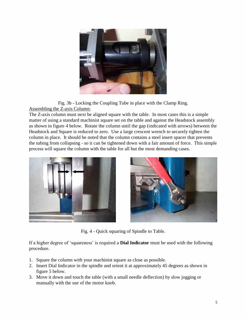
Once the coupling gap is set use the Coupling Tube Clamp Ring to lock the Coupling Tube in
place. Position it all the way to the front of the Coupling Tube and tighten down the Set Screw
as shown in figure 3b below.
5
Fig. 3b - Locking the Coupling Tube in place with the Clamp Ring.
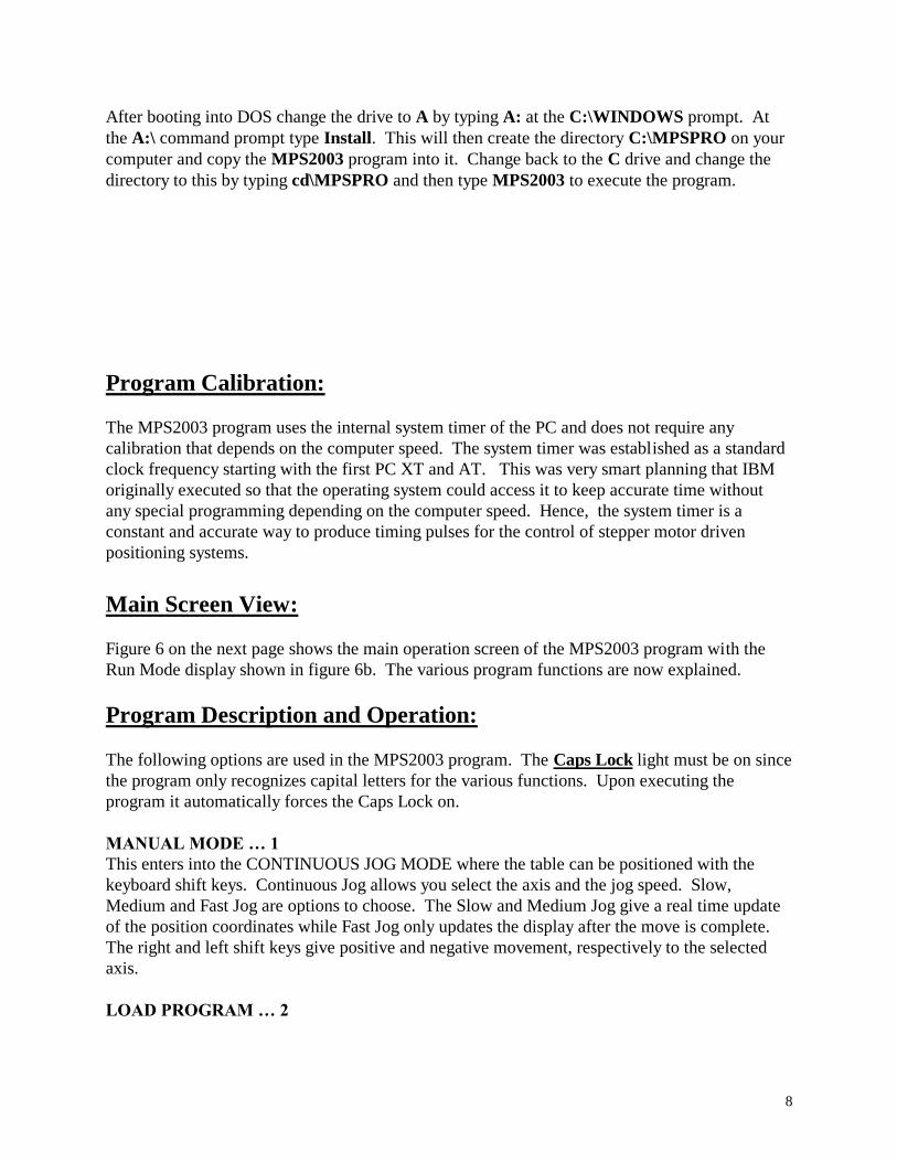
Assembling the Z-axis Column:
The Z-axis column must next be aligned square with the table. In most cases this is a simple
matter of using a standard machinist square set on the table and against the Headstock assembly
as shown in figure 4 below. Rotate the column until the gap (indicated with arrows) between the
Headstock and Square is reduced to zero. Use a large crescent wrench to securely tighten the
column in place. It should be noted that the column contains a steel insert spacer that prevents
the tubing from collapsing - so it can be tightened down with a fair amount of force. This simple
process will square the column with the table for all but the most demanding cases.
Fig. 4 - Quick squaring of Spindle to Table.
If a higher degree of ‘squareness’ is required a Dial Indicator must be used with the following
procedure.
1. Square the column with your machinist square as close as possible.
2. Insert Dial Indicator in the spindle and orient it at approximately 45 degrees as shown in
figure 5 below.
3. Move it down and touch the table (with a small needle deflection) by slow jogging or
manually with the use of the motor knob.

6
4. Move the indicator to the Left Side of the table and zero out the indicator. 5. Sweep the indicator to the Right Side and note the indicator deflection. 6. Carefully adjust the column until the indicator needle deflects to ½ of the previous reading. 7. Sweep the indicator back to the Left Side and note the indicator deflection. 8. Adjust the column again until the reading is ½ of what it was. 9. Repeat process 5 to 8 until your iterations show no dial indicator movement. 10. Carefully tighten down the column making sure it stays in place.
Fig. 5 - Precise Squaring of the Column using a Dial Indicator
This completes the initial mechanical setup of the MicroMill System. You are now ready to
proceed onward with installing the software, jogging the axes around and then running the
sample programs.

7
MPS2003 version 3.0
Operation Manual
Kurt E. Daley
December 2003
Introduction:
The MPS2003 program is a standard universal G-Code interpreter package that was designed
with many full size CNC machining center features in mind. It supports most of the commonly
used G and M codes that are used in the world today. Hence, the user that masters all its
capabilities should be well prepared to run similar equipment in a modern day CNC machine
shop. The MPS2003 program will import standard post-processed ASCII G-Code files from
almost any CAD/CAM system.
Program Installation:
Reboot your computer into DOS MODE and then insert the floppy into the A drive of your
computer. The program must run under the Real Time DOS MODE kernel in order to function
properly. If you are using Windows 95 or 98 click on the start button and select Shut Down.
From there select Restart in MS-DOS mode and click OK. The computer will then reboot into
the Real Time DOS MODE kernel at this point. If you are running Windows 2000 the real time
DOS MODE kernel is not immediately accessible from the desktop. In this case you must
BOOT your computer with a bootable floppy disk containing the DOS operating system. This
bypasses the entire Windows operating system that is installed on the computer and gives control
back to the real time DOS MODE kernel.
8
After booting into DOS change the drive to A by typing A: at the C:\WINDOWS prompt. At
the A:\ command prompt type Install. This will then create the directory C:\MPSPRO on your
computer and copy the MPS2003 program into it. Change back to the C drive and change the
directory to this by typing cd\MPSPRO and then type MPS2003 to execute the program.
Program Calibration:
The MPS2003 program uses the internal system timer of the PC and does not require any
calibration that depends on the computer speed. The system timer was established as a standard
clock frequency starting with the first PC XT and AT. This was very smart planning that IBM
originally executed so that the operating system could access it to keep accurate time without
any special programming depending on the computer speed. Hence, the system timer is a
constant and accurate way to produce timing pulses for the control of stepper motor driven
positioning systems.
Main Screen View:
Figure 6 on the next page shows the main operation screen of the MPS2003 program with the
Run Mode display shown in figure 6b. The various program functions are now explained.
Program Description and Operation:
The following options are used in the MPS2003 program. The Caps Lock light must be on since
the program only recognizes capital letters for the various functions. Upon executing the
program it automatically forces the Caps Lock on.
MANUAL MODE … 1
This enters into the CONTINUOUS JOG MODE where the table can be positioned with the
keyboard shift keys. Continuous Jog allows you select the axis and the jog speed. Slow,
Medium and Fast Jog are options to choose. The Slow and Medium Jog give a real time update
of the position coordinates while Fast Jog only updates the display after the move is complete.
The right and left shift keys give positive and negative movement, respectively to the selected
axis.
LOAD PROGRAM … 2
9
This is where you input the filename of the program you wish to execute. The default file
directory is C:\MPSPRO and can be changed with option 9. The filename can have any one to
three letter appendage. Once entered this will be the current or active program to be executed.
When Load Program is selected the user is first prompted for a filename extension. It is entered
as a one to three letter extension with NO decimal or period at the beginning. Pressing Enter
with no extension typed out retains the previously selected extension. Upon pressing Enter the
files are displayed 15 at a time. Pressing the spacebar selects the next 15 files in the directory
and so on with a wrap around to the beginning when all the files have been displayed. The Up
and Down Arrow keys are used to select the file that is highlighted in Light Blue. Pressing Enter
selects the highlighted file.
RUN PROGRAM .. 3
This executes the active program that is displayed. The program is read line by line from the
drive and is executed as a DNC program. Upon entry the screen displays START PROGRAM
and prompts the user with the following options:
C = CONTINUOUS, S = SINGLE STEP
F = FEED CHANGE, M = MAIN MENU
Selecting S executes the next program line and pauses while C executes the program in the
normal continuous fashion.
ZERO AXIS … 4
This allows the user to selectively zero out the X, Y, Z or A axis one at a time. Hitting the
Spacebar cancels this action. Zeroing all the axes sets the current machine tool position as the
new (0,0,0,0) absolute reference point.
SET SCALE … 5
The program can be scaled with this option. The entered value is used as a direct multiplier on
all the axes X, Y, Z and A. All program coordinates are scaled by the value displayed.
SET DEPTH INC … 6
This parameter allows the user to scale only the Z-axis movement for multiple depth passes into
the material. The value entered must be a whole positive integer and sets how many passes will
be executed to get to the final Z depth. The program is essentially just executed multiple times
with each new execution adding the Z depth increment value until the final depth is reached.
Note: Resetting the program with option R always sets the Z Depth Scale = 1. Hence, you must
first reset the program and then set the Z Depth Scale again for it to scale the Z-axis as desired.
Example: The following program creates a 1.0 x 1.0 inch box with a cut depth of 0.5 inches.
Setting the Depth increment to 5 would cause the program to first start at the depth 0.1 inches
and repeat with the depth 0.2 inches and so on until the final depth of 0.5 inches is reached. In
this case the program is repeated 5 times to get to the final depth.

10
G01 Z0.5F5.0
G01 X1.0F10.0
G01 Y1.0
G01 X0.0
G01 Y0.0
This is a very useful function to use when you are cutting materials other than machinable wax
such as Aluminum or Steel. In these cases a single cutting pass to the final cut depth is not
possible and must be broken up into several light cutting passes. A good example of using this
function is reproducing a digitized surface in metals.
CLEAR DISPLAY … 7
Rewrites the whole screen thereby clearing any program image displayed in the plot
window.
MDI MODE … 8
Allows the user to input a single line of code that is executed immediately after Enter is pressed.
It remains in MDI mode until a blank line is Entered.
FILE DIRECTORY .. 9
Allows the file directory to be changed. The directory is entered in the standard format such as
C:\MPSPRO. Entering a blank line retains the current directory.
RAPID/ACCEL…A
Rapid Start sets the starting speed in (steps/sec) for rapid moves or fast jogging. Accel Steps sets
the number of acceleration steps used to ramp up to the final rapid speed. Step Inc sets the
acceleration step increment multiplier used in the ramp. Typically Rapid Start = 600, Accel
Steps = 800 and Step Inc = 2. This gives a start speed of 400 steps/sec and a final speed of 600
+ 800 x 2 = 2200 steps/sec.
PLOT SCALE … L
Allows zooming in or out on the display plot window. Smaller numbers zoom out while larger
numbers zoom in.
PLOT PREVIEW … P
A useful option that allows the program to be plotted on the screen without movement of the
axes. Pressing P toggles between Plot Preview and Run Mode. In Run Mode all axes are
enabled and ready for movement commands.
CONTINUE … C
Continues the program execution where it was stopped by a Slide Hold operation.
PLOT VIEW … V
Sets the viewing window to display a 3-D PLOT VIEW perspective or XY PLANE VIEW of the
part program. Pressing V toggles it between the two different views.
11
JOG INCREMENT … J
Enters the JOG INCREMENT MODE that allows the user to specify a JOG INC distance to
move the axes. Upon entering a value the axes are moved with the following keys. Pressing
Enter with no value retains the previous value.
Right Arrow = Move X-axis to the right for + X move.
Left Arrow = Move X-axis to the left for - X move.
Up Arrow = Move Y-axis forward for + Y move.
Down Arrow = Move Y-axis backward for - Y move.
Page Up = Move Z-axis upward for + Z move.
Page Down = Move Z-axis downward for - Z move.
+ Key = Rotate A-axis CW for + A move.
- Key = Rotate A-axis CCW for - A move.
FEED CHANGE … F
Sets the Feed Rate Override value as a percentage. All F values encountered in a program will
be scaled by the percentage displayed.
XY OFFSET … O
Sets the center of the view screen to the specified X and Y values entered. This is useful for
centering parts in the view screen that were created at a different X,Y coordinate reference
position.
RESET PROGRAM … R
Reset the current program to the beginning for execution. Once it is reset the program can be
executed again with the RUN PROGRAM option # 3.
QUIT PROGRAM … Q
Terminates the MPS2003 program and return back to the system DOS prompt. The current
X,Y,Z,A coordinates, Tool H offsets and Printer Ports are all saved to the file PARAM.DAT
upon program exit. When prompted only entering a Y will terminate the program. A blank or
anything else will return back to the main menu.
PORT BASE … B
Used to change the printer port address that the computer will output control signals to. Only
three options are available - 632, 888 or 956. All PC compatible computers use only these three
port bases. On a standard IBM compatible system the XYZ PORT address is almost always set
to 888. The A PORT address is usually set to 632 which is what the 4th
axis printer port card
(supplied with the rotary table option) is configured for.
SWITCH MENU … M
Switches to the 2nd
Menu Display of the various functions
REPEAT NUMBER … N
12
Allows the program to be repeated any specified number from 1 to 10000 times. The display
shows the current loop number being executed along with the total number of times remaining.
BACKLASH COMP … K
Sets backlash compensation for each axis. The backlash is entered directly as a value in
INCHES (or mm when in metric mode). Backlash compensation is enabled with option 1 or
disabled with option 2.
CHANGE UNITS … U
Allows INCH, mm or Custom units to be used. Once activated all movements will be in the
units specified.
DISPLAY TOOLS … T
Display the Tool Length Offset table. A total of 10 tool offsets can be used.
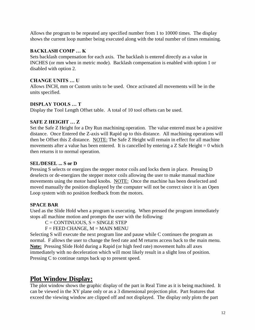
SAFE Z HEIGHT … Z
Set the Safe Z Height for a Dry Run machining operation. The value entered must be a positive
distance. Once Entered the Z-axis will Rapid up to this distance. All machining operations will
then be Offset this Z distance. NOTE: The Safe Z Height will remain in effect for all machine
movements after a value has been entered. It is cancelled by entering a Z Safe Height = 0 which
then returns it to normal operation.
SEL/DESEL ... S or D
Pressing S selects or energizes the stepper motor coils and locks them in place. Pressing D
deselects or de-energizes the stepper motor coils allowing the user to make manual machine
movements using the motor hand knobs. NOTE: Once the machine has been deselected and
moved manually the position displayed by the computer will not be correct since it is an Open
Loop system with no position feedback from the motors.
SPACE BAR
Used as the Slide Hold when a program is executing. When pressed the program immediately
stops all machine motion and prompts the user with the following:
C = CONTINUOUS, S = SINGLE STEP
F = FEED CHANGE, M = MAIN MENU
Selecting S will execute the next program line and pause while C continues the program as
normal. F allows the user to change the feed rate and M returns access back to the main menu.
Note: Pressing Slide Hold during a Rapid (or high feed rate) movement halts all axes
immediately with no deceleration which will most likely result in a slight loss of position.
Pressing C to continue ramps back up to present speed.
Plot Window Display:
The plot window shows the graphic display of the part in Real Time as it is being machined. It
can be viewed in the XY plane only or as a 3 dimensional projection plot. Part features that
exceed the viewing window are clipped off and not displayed. The display only plots the part
13
features that are below the material surface which is assumed to be set at Z = 0. All movements
with Z greater then 0 are not displayed. The plot scale and X,Y offset values must be properly
chosen, depending on the part being machined, in order to show the entire part in the Plot
Window.
Using the XY OFFSET command:
The plot window display is initially centered with the (X=0,Y=0) position being in the center of
the plot window. If the reference position of a part program is located somewhere other then a
(0,0) position it may only be partially displayed in the window or not displayed at all. The XY
OFFSET command can be used to move the plot window coordinate system to display such a
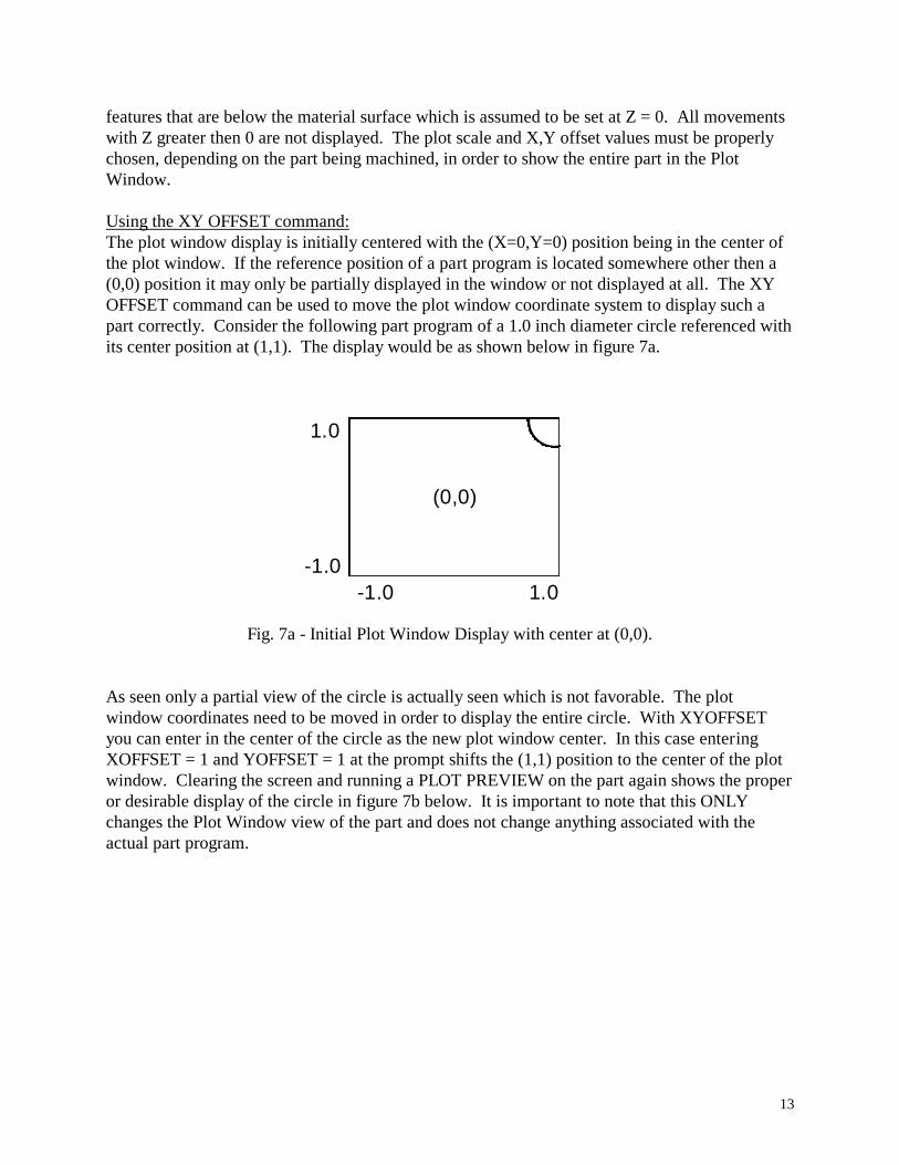
part correctly. Consider the following part program of a 1.0 inch diameter circle referenced with
its center position at (1,1). The display would be as shown below in figure 7a.
1.0
-1.0
-1.0 1.0
(0,0)
Fig. 7a - Initial Plot Window Display with center at (0,0).
As seen only a partial view of the circle is actually seen which is not favorable. The plot
window coordinates need to be moved in order to display the entire circle. With XYOFFSET
you can enter in the center of the circle as the new plot window center. In this case entering
XOFFSET = 1 and YOFFSET = 1 at the prompt shifts the (1,1) position to the center of the plot
window. Clearing the screen and running a PLOT PREVIEW on the part again shows the proper
or desirable display of the circle in figure 7b below. It is important to note that this ONLY
changes the Plot Window view of the part and does not change anything associated with the
actual part program.

14
1.5
-0.5
-0.5 1.5
(1,1)
Fig. 7b - Shifted Plot Window Display with center at (1,1).
The part reference position may not always be known and in this case you just run a PLOT
PREVIEW and find where it is displayed at. You then guess at the center coordinates and enter
them as the XYOFFSET values and PLOT PREVIEW it again to see if it’s where you want it. If
not repeat the process. Note: The part may not be displayed at all in which case just zoom out
with a small PLOT SCALE value (0.2 or 0.3 is usually good) until the part is displayed. The
center position can then be guessed and entered. Then zoom in again and repeat as before.
NOTE: Graphically displaying your part program may not even be of interest to you if you have
already designed and displayed it in your Cad/Cam system. In this case you can bypass the
above procedure and just let the part program run without caring about its plot window display.
It is nice, though, to display it properly in Real Time to see the machining progress if the actual
part being machined is not viewable for some reason.
Example Program Setup and Execution:
Several example programs are included with the MPS2003 program to guide the user through the
proper setup and execution of various machining operations. The user is encouraged to spend a
few moments going through the following examples step by step to become familiar with the
various attributes of the MPS2003 program and the MicroMill itself. The part programs will
start with the simplest and proceed to more complex machining operations and setups.
Example Program # 1 (Engraving Text):
This first example will demonstrate the simple use of the MicroMill for engraving text. The
program file name is TEXTDEMO.TAP and will engrave the MicroMill text as shown in figure
8a below. The text letter height is 0.25 inches with a total text length of 2 inches. In this
example you want to use an engraving tool bit or a small diameter flat end mill. Select a 1/16”
diameter flat end milling cutter and insert it into the spindle. The cut depth is programmed to be
0.025 inches with an X,Y feed of 20 inch/min. and Z plunge feed of 10 inch/min.

15
The MicroMill
Fig. 8a - The MicroMill text engraving demo.
Setup Procedure:
1. Execute the MPS2003 program by typing MPS2003 at the DOS prompt.
2. Select option # 1 MANUAL JOG.
3. Select F for Fast Jogging.
4. Select each axis and Jog the machine to a safe material loading position.
5. Secure Sample Material # 1 plate (3” x 2” x 0.25”) in the vise and tighten it down.
6. Fast Jog the X and Y axis to the approximate center of the material.
7. Fast Jog the Z to approximately 0.5 inches above the material surface.
8. Select M and Medium Jog the tool bit to 0.1 inches above.
9. Select S and Slow Jog the tool bit to the surface.
10. Type Q to quit
11. Type 4 and zero out each axis one by one.
12. Go back to CONTINUOUS JOG and move the Z-axis approximately 1.0 inch above the
material surface.
13. The machine is now ready to execute the part program.
Executing the Program:
You are now ready to load and execute the program with the following steps.
1. Type option # 2 LOAD PROGRAM.
2. Type TAP (with no “.” prefix) at the prompt for a file extension. This will select .TAP files.
3. Select the program TEXTDEMO.TAP with the arrow keys and hit Enter.
16
4. Type P to enter the Plot Preview mode. This will then display PLOT PREVIEW on the
screen.
5. Type option # 3 RUN PROGRAM.
At this point the text will be drawn in the plot window as in figure 8a showing a preview of what
the machined geometry will be. It is always a good idea to plot preview the part before actually
machining it to make sure it was properly designed or post processed by your Cad/Cam program.
If the plot preview looks correct you can next execute a DRY RUN of the part to see if the
material is positioned correctly and that the tool isn’t going to run into any fixtures you may have
on the table. The following steps allow you to DRY RUN the part which executes the X andY
axis movements with the Z-axis movements offset up a specified safe height from the material
surface.
1. Type P to toggle out of Plot Preview mode and back to Run Mode.
2. Type Z which will then prompt the user for a SAFE Z HEIGHT.
3. Enter a SAFE Z HEIGHT of 1. The Z-axis will rapid to 1.0 inch from the material surface
and the words DRY RUN will be displayed on the screen.
4. Type option # 3 to run the program.
The machine will execute the X,Y and Z movements at this time with the Z-axis position offset
1.0 inch upward. If the movement looks correct with no collisions with fixtures or anything else
you are now finally ready to start machining the part. The following machines the part program.
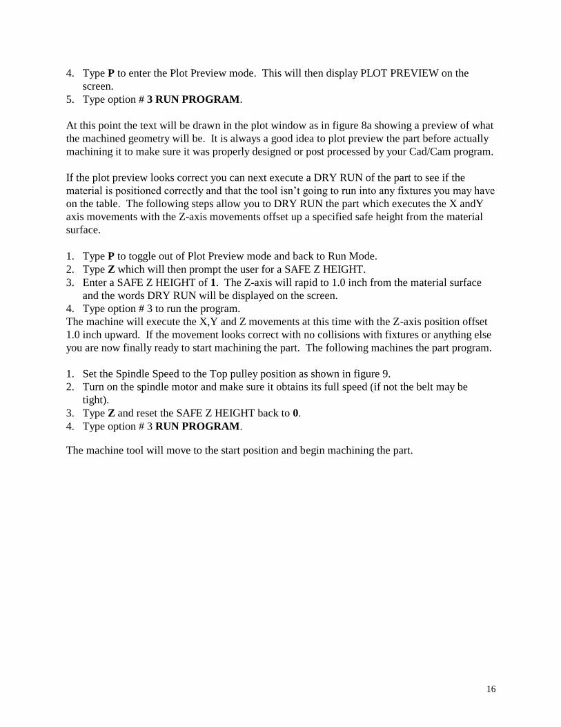
1. Set the Spindle Speed to the Top pulley position as shown in figure 9.
2. Turn on the spindle motor and make sure it obtains its full speed (if not the belt may be
tight).
3. Type Z and reset the SAFE Z HEIGHT back to 0.
4. Type option # 3 RUN PROGRAM.
The machine tool will move to the start position and begin machining the part.
17
Fig. 9 - Spindle set to top speed position.
.NOTE:
Once you become familiar with the machine and setting up the reference positions and so forth
you may bypass the Preview and Dry Run steps and machine the part directly. The preceding
process, though, is ALWAYS A GOOD IDEA when setting up a new part, experimenting with
different Feed values or changing to a new fixture location.
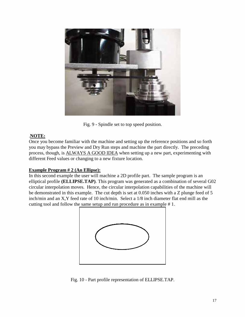
Example Program # 2 (An Ellipse):
In this second example the user will machine a 2D profile part. The sample program is an
elliptical profile (ELLIPSE.TAP). This program was generated as a combination of several G02
circular interpolation moves. Hence, the circular interpolation capabilities of the machine will
be demonstrated in this example. The cut depth is set at 0.050 inches with a Z plunge feed of 5
inch/min and an X,Y feed rate of 10 inch/min. Select a 1/8 inch diameter flat end mill as the
cutting tool and follow the same setup and run procedure as in example # 1.
Fig. 10 - Part profile representation of ELLIPSE.TAP.
18
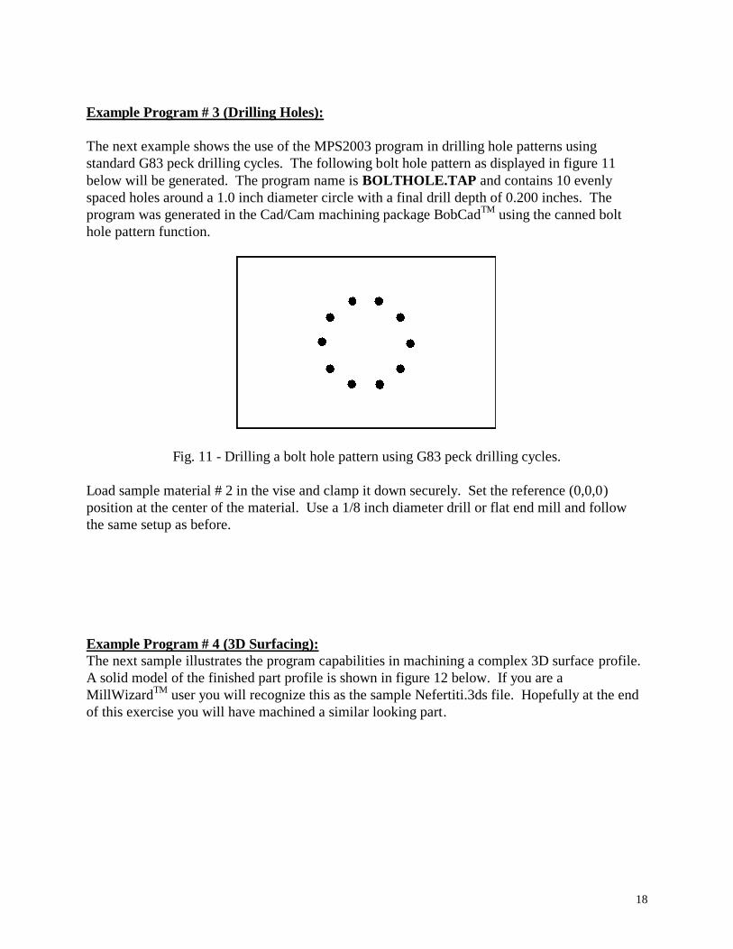
Example Program # 3 (Drilling Holes):
The next example shows the use of the MPS2003 program in drilling hole patterns using
standard G83 peck drilling cycles. The following bolt hole pattern as displayed in figure 11
below will be generated. The program name is BOLTHOLE.TAP and contains 10 evenly
spaced holes around a 1.0 inch diameter circle with a final drill depth of 0.200 inches. The
program was generated in the Cad/Cam machining package BobCadTM
using the canned bolt
hole pattern function.
Fig. 11 - Drilling a bolt hole pattern using G83 peck drilling cycles.
Load sample material # 2 in the vise and clamp it down securely. Set the reference (0,0,0)
position at the center of the material. Use a 1/8 inch diameter drill or flat end mill and follow
the same setup as before.
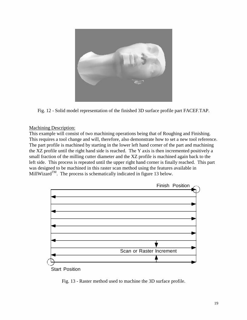
Example Program # 4 (3D Surfacing):
The next sample illustrates the program capabilities in machining a complex 3D surface profile.
A solid model of the finished part profile is shown in figure 12 below. If you are a
MillWizardTM
user you will recognize this as the sample Nefertiti.3ds file. Hopefully at the end
of this exercise you will have machined a similar looking part.
19
Fig. 12 - Solid model representation of the finished 3D surface profile part FACEF.TAP.
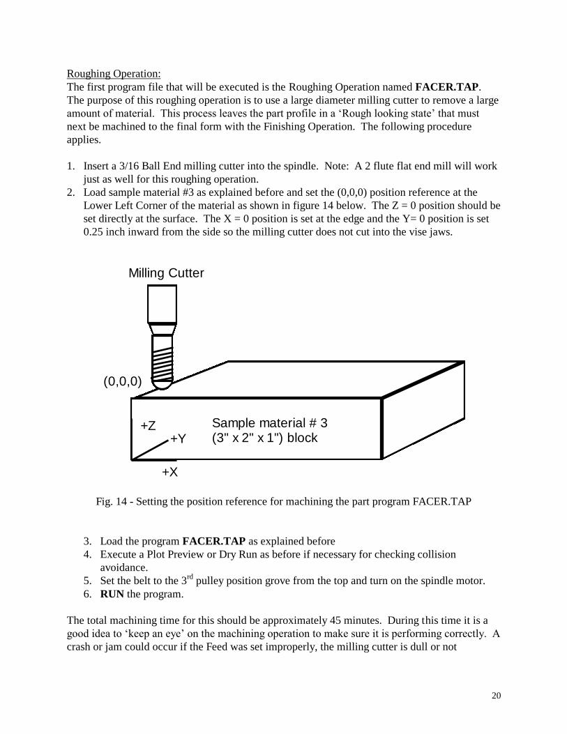
Machining Description:
This example will consist of two machining operations being that of Roughing and Finishing.
This requires a tool change and will, therefore, also demonstrate how to set a new tool reference.
The part profile is machined by starting in the lower left hand corner of the part and machining
the XZ profile until the right hand side is reached. The Y axis is then incremented positively a
small fraction of the milling cutter diameter and the XZ profile is machined again back to the
left side. This process is repeated until the upper right hand corner is finally reached. This part
was designed to be machined in this raster scan method using the features available in
MillWizardTM
. The process is schematically indicated in figure 13 below.
Start Position
Finish Position
Scan or Raster Increment
Fig. 13 - Raster method used to machine the 3D surface profile.
20
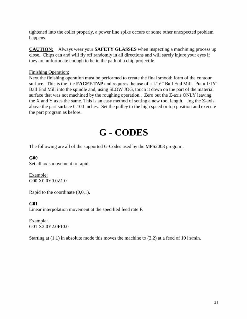
Roughing Operation:
The first program file that will be executed is the Roughing Operation named FACER.TAP.
The purpose of this roughing operation is to use a large diameter milling cutter to remove a large
amount of material. This process leaves the part profile in a ‘Rough looking state’ that must
next be machined to the final form with the Finishing Operation. The following procedure
applies.
1. Insert a 3/16 Ball End milling cutter into the spindle. Note: A 2 flute flat end mill will work
just as well for this roughing operation.
2. Load sample material #3 as explained before and set the (0,0,0) position reference at the
Lower Left Corner of the material as shown in figure 14 below. The Z = 0 position should be
set directly at the surface. The X = 0 position is set at the edge and the Y= 0 position is set
0.25 inch inward from the side so the milling cutter does not cut into the vise jaws.
+X
+Y+Z
(0,0,0)
Sample material # 3(3" x 2" x 1") block
Milling Cutter
Fig. 14 - Setting the position reference for machining the part program FACER.TAP
3. Load the program FACER.TAP as explained before
4. Execute a Plot Preview or Dry Run as before if necessary for checking collision
avoidance.
5. Set the belt to the 3rd
pulley position grove from the top and turn on the spindle motor.
6. RUN the program.
The total machining time for this should be approximately 45 minutes. During this time it is a
good idea to ‘keep an eye’ on the machining operation to make sure it is performing correctly. A
crash or jam could occur if the Feed was set improperly, the milling cutter is dull or not
21
tightened into the collet properly, a power line spike occurs or some other unexpected problem
happens.
CAUTION: Always wear your SAFETY GLASSES when inspecting a machining process up
close. Chips can and will fly off randomly in all directions and will surely injure your eyes if
they are unfortunate enough to be in the path of a chip projectile.
Finishing Operation:
Next the finishing operation must be performed to create the final smooth form of the contour
surface. This is the file FACEF.TAP and requires the use of a 1/16” Ball End Mill. Put a 1/16”
Ball End Mill into the spindle and, using SLOW JOG, touch it down on the part of the material
surface that was not machined by the roughing operation.. Zero out the Z-axis ONLY leaving
the X and Y axes the same. This is an easy method of setting a new tool length. Jog the Z-axis
above the part surface 0.100 inches. Set the pulley to the high speed or top position and execute
the part program as before.
G - CODES
The following are all of the supported G-Codes used by the MPS2003 program.
G00
Set all axis movement to rapid.
Example:
G00 X0.0Y0.0Z1.0
Rapid to the coordinate (0,0,1).
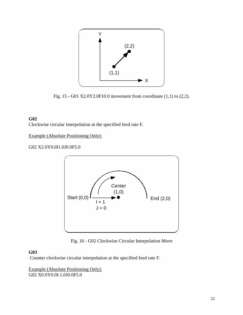
G01
Linear interpolation movement at the specified feed rate F.
Example:
G01 X2.0Y2.0F10.0
Starting at (1,1) in absolute mode this moves the machine to (2,2) at a feed of 10 in/min.
22
Y
X
(1,1)
(2,2)
Fig. 15 - G01 X2.0Y2.0F10.0 movement from coordinate (1,1) to (2,2).
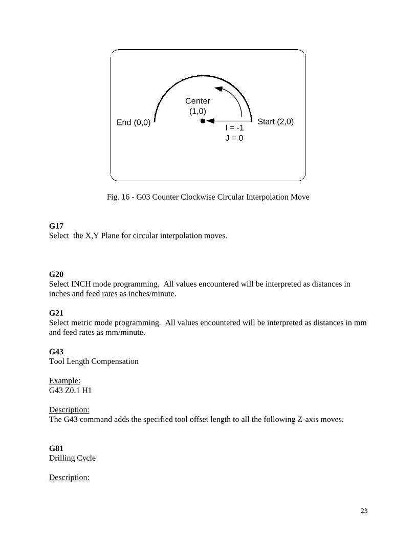
G02
Clockwise circular interpolation at the specified feed rate F.
Example (Absolute Positioning Only):
G02 X2.0Y0.0I1.0J0.0F5.0
Start (0,0) End (2,0)I = 1
J = 0
Center
(1,0)
Fig. 16 - G02 Clockwise Circular Interpolation Move
G03
Counter clockwise circular interpolation at the specified feed rate F.
Example (Absolute Positioning Only):
G02 X0.0Y0.0I-1.0J0.0F5.0
23
Center
(1,0)
End (0,0)I = -1
J = 0
Start (2,0)
Fig. 16 - G03 Counter Clockwise Circular Interpolation Move
G17
Select the X,Y Plane for circular interpolation moves.
G20
Select INCH mode programming. All values encountered will be interpreted as distances in
inches and feed rates as inches/minute.
G21
Select metric mode programming. All values encountered will be interpreted as distances in mm
and feed rates as mm/minute.
G43
Tool Length Compensation
Example:
G43 Z0.1 H1
Description:
The G43 command adds the specified tool offset length to all the following Z-axis moves.
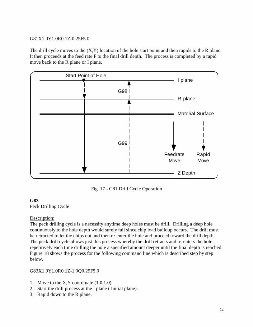
G81
Drilling Cycle
Description:
24
G81X1.0Y1.0R0.1Z-0.25F5.0
The drill cycle moves to the (X,Y) location of the hole start point and then rapids to the R plane.
It then proceeds at the feed rate F to the final drill depth. The process is completed by a rapid
move back to the R plane or I plane.
Material Surface
R plane
I plane
G98
G99
Start Point of Hole
Z Depth
Feedrate
Move
Rapid
Move
Fig. 17 - G81 Drill Cycle Operation
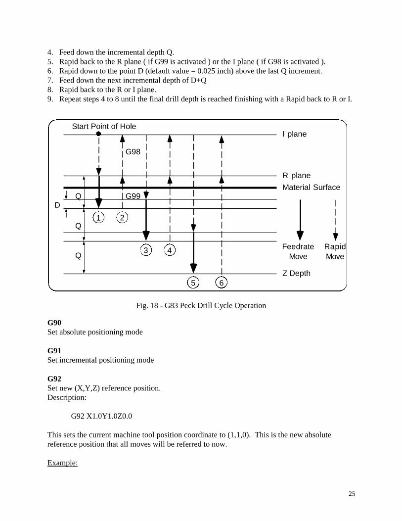
G83
Peck Drilling Cycle
Description:
The peck drilling cycle is a necessity anytime deep holes must be drill. Drilling a deep hole
continuously to the hole depth would surely fail since chip load buildup occurs. The drill must
be retracted to let the chips out and then re-enter the hole and proceed toward the drill depth.
The peck drill cycle allows just this process whereby the drill retracts and re-enters the hole
repetitively each time drilling the hole a specified amount deeper until the final depth is reached.
Figure 18 shows the process for the following command line which is described step by step
below.
G83X1.0Y1.0R0.1Z-1.0Q0.25F5.0
1. Move to the X,Y coordinate (1.0,1.0).
2. Start the drill process at the I plane ( Initial plane).
3. Rapid down to the R plane.
25
4. Feed down the incremental depth Q.
5. Rapid back to the R plane ( if G99 is activated ) or the I plane ( if G98 is activated ).
6. Rapid down to the point D (default value = 0.025 inch) above the last Q increment.
7. Feed down the next incremental depth of D+Q
8. Rapid back to the R or I plane.
9. Repeat steps 4 to 8 until the final drill depth is reached finishing with a Rapid back to R or I.
Material Surface
R plane
1 2
G99
G98
5
43
Start Point of Hole
Z Depth
Feedrate
Move
Rapid
Move
QD
I plane
Q
Q
6
Fig. 18 - G83 Peck Drill Cycle Operation
G90
Set absolute positioning mode
G91
Set incremental positioning mode
G92
Set new (X,Y,Z) reference position.
Description:
G92 X1.0Y1.0Z0.0
This sets the current machine tool position coordinate to (1,1,0). This is the new absolute
reference position that all moves will be referred to now.
Example:

26
The G92 command can be very useful for repeating a part program at numerous locations.
Suppose you are manufacturing small diamond inlays from wood and wish to cut out 4 per each
piece of wood block you have. You have defined the bottom vertex as the reference position for
the start of each piece. Figure 19 shows the diamond patterns with the starting coordinates of
each piece you wish to produce.
(0,0) (1,0)
(1.5.1)(0.5,1)
Fig. 19 - Machining multiple diamond inlays.
The following program would be used in this case. Note: To execute M97 subroutines requires
the use of the control program MPSM97.EXE or TEXTM97.EXE.
M97 P100
G92 X-1.0Y0.0
M97 P100
G92 X-0.5Y-1.0
M97 P100
G92 X1.0Y0.0
M97 P100
G00 X-0.5Y-1.0
G92 X0.0Y0.0
M02
N100
G00G90X0.0Y0.0Z0.1
G01 Z-0.13 F10
X0.375Y0.75
X0.0Y1.50

27
X-0.375Y0.75
X0.0Y0.0
Z0.1
M99
G98
Return to I plane for drill cycles.
G99
Return to R plane for drill cycles.
M - Codes
MO
Program Stop. Upon reading an MO command the program stops and waits for the user to press
C to continue program execution.
M6
Tool Change. Upon reading an M6 command the program stops and waits for the user to press
C to continue program execution.
28
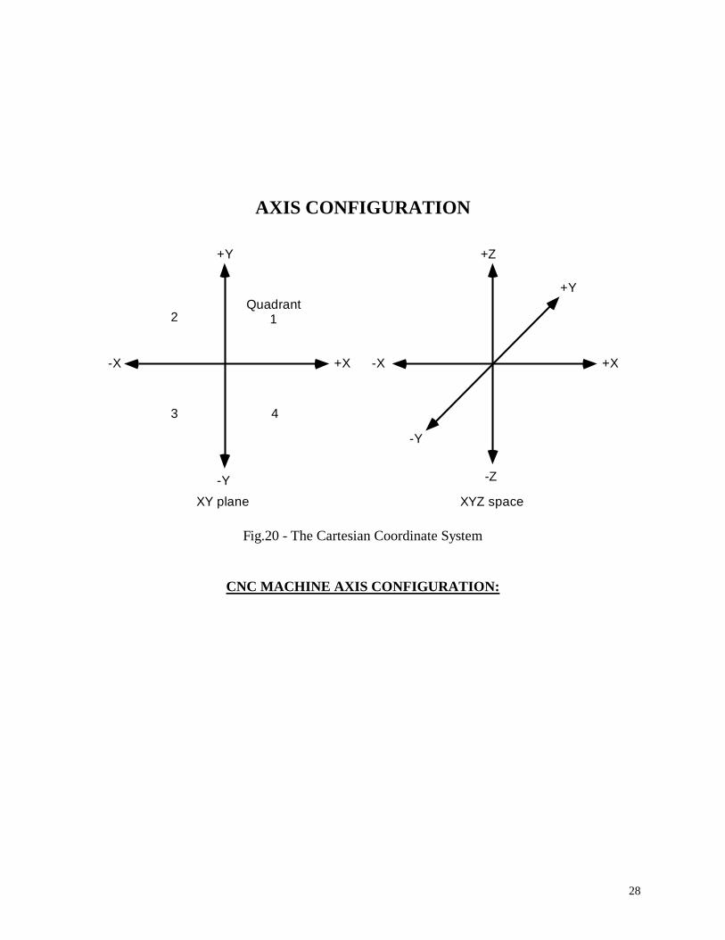
AXIS CONFIGURATION
+X-X
+Y
-Y
-Z
+Z
Quadrant12
3 4
+X-X
+Y
-Y
XY plane XYZ space
Fig.20 - The Cartesian Coordinate System
CNC MACHINE AXIS CONFIGURATION:
29
+X-X
+Y
-Y
+Z
-Z
Spindle
Machine table
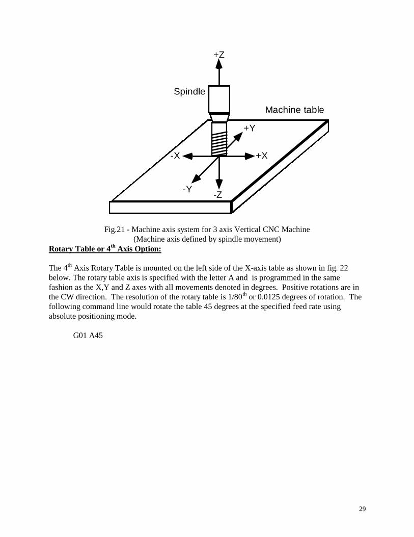
Fig.21 - Machine axis system for 3 axis Vertical CNC Machine
(Machine axis defined by spindle movement)
Rotary Table or 4th
Axis Option:
The 4th
Axis Rotary Table is mounted on the left side of the X-axis table as shown in fig. 22
below. The rotary table axis is specified with the letter A and is programmed in the same
fashion as the X,Y and Z axes with all movements denoted in degrees. Positive rotations are in
the CW direction. The resolution of the rotary table is 1/80th
or 0.0125 degrees of rotation. The
following command line would rotate the table 45 degrees at the specified feed rate using
absolute positioning mode.
G01 A45

30
Fig. 22 - Standard mounting position of the 4th
Axis Rotary Table.
TROUBLESHOOTING PROBLEMS
PROBLEM: System does not work at all.
CHECK: Fuse in back of unit (2A).
PROBLEM: The motors don’t rotate at all when jogging.
CHECK: If all the axis step motors don’t rotate and just vibrate when jogging most likely
there is a problem with the PRINTER CABLE or PRINTER PORT of your
computer. Try another cable and make sure no cable or port pins are bent out
of shape.
PROBLEM: Can’t get table to position at all - the motors just don’t work.

31
CHECK: The PORT BASE is probably configured to the wrong address.
Change the port address by typing B and change the XYZ PORT BASE
to either 632, 888 or 956.
PROBLEM: The motors don’t step smoothly. There is an audible clicking that occurs when
they are running.
CHECK: Most likely this is due to running the control program in Windows under a
DOS Prompt. Shut down the computer and Restart it in DOS MODE.
PROBLEM: Motors run at slow speeds with low torque, but not at high speeds at all.
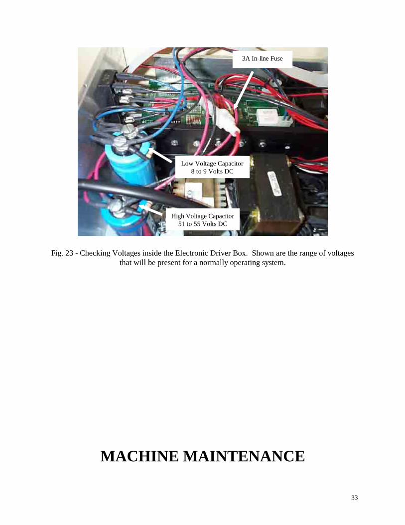
CHECK: Open up drive unit and check the 3 Amp in-line fuse (Fig. 23 below) first.
If the fuse is good, measure the voltage across the shorter capacitor with RED
wires (Fig. 23) to see if there is approx. 55 Vdc. If not the in-line fuse may not be
making a good connection - correct if necessary.
PROBLEM: Motors have low torque or are stepping incorrectly
CHECK: Voltage Line Power to see if voltage is 110 to 120 Vac.
PROBLEM: The step motors are humming at a low frequency pitch.
CHECK: This is the high voltage chopping frequency of 60 Hz. This is normally no
problem, but may become a problem if the AC line Voltage drops below
110 VAC. If the in-line fuse keeps blowing this is the case and the
trimmer potentiometers on both circuit boards must be adjusted CW
looking at the unit from the front panel.
PROBLEM: The X, Y or Z axis is not stepping correctly.
CHECK: This could be a problem with the parallel port of the computer.
Check first if all the bit lines of the computer port are working correctly.
If this checks OK then there may be a problem with the driver unit.
Call the factory in this case.
PROBLEM: The motors will not step at high speeds - they just keep jamming.
CHECK: This is inherent in any open-loop system pushed beyond its capacity.
The load on the table may be too large, the screw or ways may not
be properly lubricated, the lead screw nut is too tight or the gib adjustment
may be too tight. Under ideal conditions a single axis should achieve a maximum
translation of 60 inch/min. Simultaneous two axis movement should also
approach this, but may have to be a little slower.
PROBLEM: Table is not moving what it is programmed to move.
CHECK: You may have switched to INCH or mm mode unknowingly. Type
U and select the units you wish to use.
PROBLEM: Driver Unit gets fairly hot after prolonged idle period.
32
CHECK: This is normally no problem, but if it is going to sit idle for extended
periods of time it is best to DESELECT the table or turn the unit off.
PROBLEM: The step motors get very hot after prolonged use or idle time.
CHECK: This is most evident when running the motors at high speed which
drives them with the maximum power. Even under these conditions
the motors are dissipating less then their maximum power rating and no
danger should be present. To be safe, though, the motors should be
DESELECTed if a prolonged idle period is anticipated.
PROBLEM: The driver unit was left on with the computer turned off, the printer cable
disconnected, or while running another program other than MPS2003. In
this case the motors and driver unit may get very hot and damage may
occur if this is the case for an extended period of time.
CHECK: The driver unit needs the proper control signals provided by MPS2003 or
equivalent software to function properly and safely. DO NOT leave the
driver unit on if it is not under control of the software.
PROBLEM: The motors jam while jogging at high speed or when executing a G0
rapid movement.
CHECK: The A option parameters may need to be adjusted. The A or acceleration
parameters (See p. 10) control the amount and rate of acceleration and
deceleration necessary to obtain high speed movement. Usually motor
jamming is the result of accelerating too fast with the Step Inc parameter
set too large. Typically this value is between 1 and 2 with the higher number
giving a faster acceleration. Hence, if the motors are jamming you may need
to lower this value somewhere between 1 and 1.5.
33
Fig. 23 - Checking Voltages inside the Electronic Driver Box. Shown are the range of voltages
that will be present for a normally operating system.
MACHINE MAINTENANCE
3A In-line Fuse
Low Voltage Capacitor
8 to 9 Volts DC
High Voltage Capacitor
51 to 55 Volts DC
34
Proper maintenance and care will assure that your MicroMill system will work at peak
performance for many years of operation. Following the simple maintenance procedures below
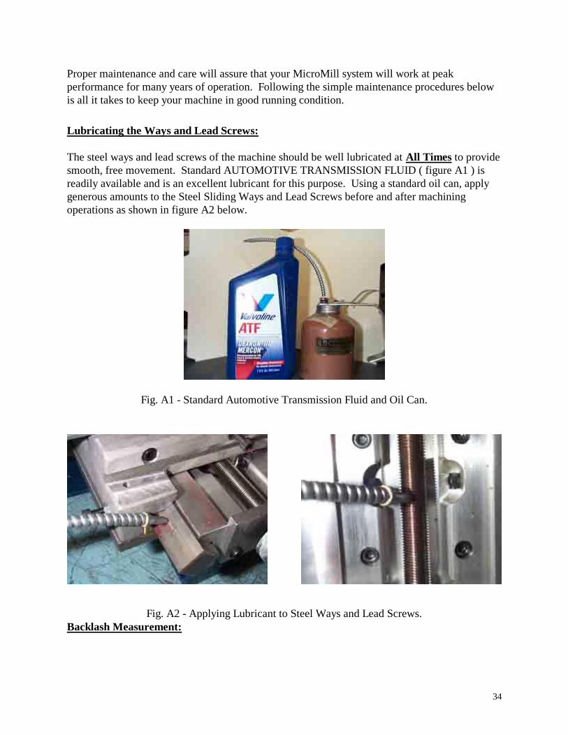
is all it takes to keep your machine in good running condition. Lubricating the Ways and Lead Screws:
The steel ways and lead screws of the machine should be well lubricated at All Times to provide
smooth, free movement. Standard AUTOMOTIVE TRANSMISSION FLUID ( figure A1 ) is
readily available and is an excellent lubricant for this purpose. Using a standard oil can, apply
generous amounts to the Steel Sliding Ways and Lead Screws before and after machining
operations as shown in figure A2 below.
Fig. A1 - Standard Automotive Transmission Fluid and Oil Can.
Fig. A2 - Applying Lubricant to Steel Ways and Lead Screws. Backlash Measurement:
35
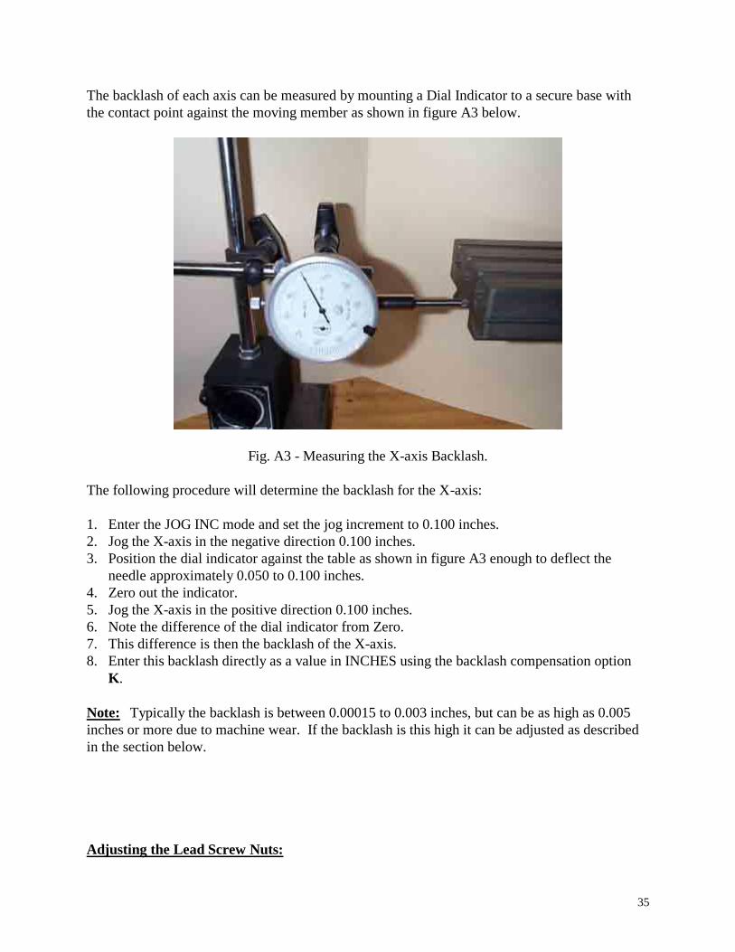
The backlash of each axis can be measured by mounting a Dial Indicator to a secure base with
the contact point against the moving member as shown in figure A3 below.
Fig. A3 - Measuring the X-axis Backlash.
The following procedure will determine the backlash for the X-axis:
1. Enter the JOG INC mode and set the jog increment to 0.100 inches.
2. Jog the X-axis in the negative direction 0.100 inches.
3. Position the dial indicator against the table as shown in figure A3 enough to deflect the
needle approximately 0.050 to 0.100 inches.
4. Zero out the indicator.
5. Jog the X-axis in the positive direction 0.100 inches.
6. Note the difference of the dial indicator from Zero.
7. This difference is then the backlash of the X-axis.
8. Enter this backlash directly as a value in INCHES using the backlash compensation option
K.
Note: Typically the backlash is between 0.00015 to 0.003 inches, but can be as high as 0.005
inches or more due to machine wear. If the backlash is this high it can be adjusted as described
in the section below.
Adjusting the Lead Screw Nuts:
36
If your machine is running on a continuous basis and has accumulated many thousands of inches
of travel on each axis throughout the years the Lead Screw Nuts may begin to show wear. This
is evident if the backlash or play is larger then you think it should be. The backlash of a new
system is typically from 0.0015 to 0.003 inches. If the backlash is larger than this the Nut may
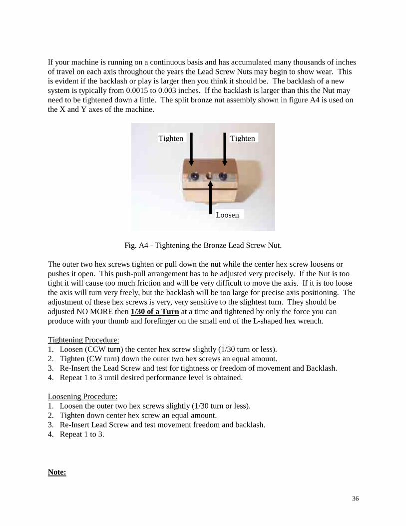
need to be tightened down a little. The split bronze nut assembly shown in figure A4 is used on
the X and Y axes of the machine.
Fig. A4 - Tightening the Bronze Lead Screw Nut.
The outer two hex screws tighten or pull down the nut while the center hex screw loosens or
pushes it open. This push-pull arrangement has to be adjusted very precisely. If the Nut is too
tight it will cause too much friction and will be very difficult to move the axis. If it is too loose
the axis will turn very freely, but the backlash will be too large for precise axis positioning. The
adjustment of these hex screws is very, very sensitive to the slightest turn. They should be
adjusted NO MORE then 1/30 of a Turn at a time and tightened by only the force you can
produce with your thumb and forefinger on the small end of the L-shaped hex wrench.
Tightening Procedure:
1. Loosen (CCW turn) the center hex screw slightly (1/30 turn or less).
2. Tighten (CW turn) down the outer two hex screws an equal amount.
3. Re-Insert the Lead Screw and test for tightness or freedom of movement and Backlash.
4. Repeat 1 to 3 until desired performance level is obtained.
Loosening Procedure:
1. Loosen the outer two hex screws slightly (1/30 turn or less).
2. Tighten down center hex screw an equal amount.
3. Re-Insert Lead Screw and test movement freedom and backlash.
4. Repeat 1 to 3.
Note:
Tighten Tighten
Loosen

37
This can be a Very Tedious process and can really throw the whole Lead Screw/Nut system out
of calibration ( Much Too Tight or Too Loose) if not done in the proper fashion. If you are not
very experienced with ‘The Feel’ a properly adjusted machine should have it is recommended
that you do not attempt this procedure.
Adjusting the Brass Gibs:
Box Way Assembly Gib:
The brass gibs may also need adjustment over time. The brass gib of the Z-Axis Box Way
Assembly is adjusted with Hex Screws on the top and bottom of the assembly as shown in figure
A5.1 below. The top screw tightens the gib on the steel way while the bottom one loosens it.
Fig. A5.1 - Box Way Brass Gib top adjustment screw.
Saddle Gib:
The brass gib on the saddle or Y-axis is adjusted with the two Hex Screws shown in figure A5.2
below. The longer middle Hex Screw is used to lock the saddle in place, which would generally
NEVER be done on a CNC machine. This would only used on the Manual MicroMill.
38
Fig. A5.2 - Brass Gib adjustment screws for the Saddle.
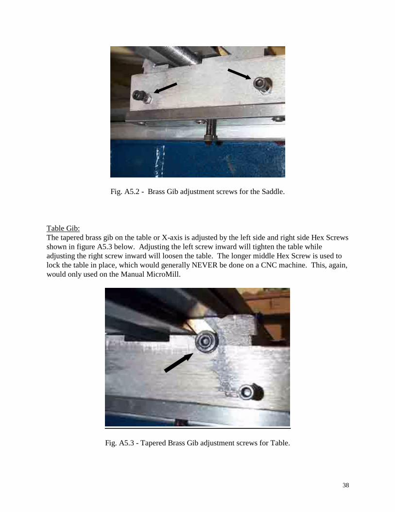
Table Gib:
The tapered brass gib on the table or X-axis is adjusted by the left side and right side Hex Screws
shown in figure A5.3 below. Adjusting the left screw inward will tighten the table while
adjusting the right screw inward will loosen the table. The longer middle Hex Screw is used to
lock the table in place, which would generally NEVER be done on a CNC machine. This, again,
would only used on the Manual MicroMill.
Fig. A5.3 - Tapered Brass Gib adjustment screws for Table.
39
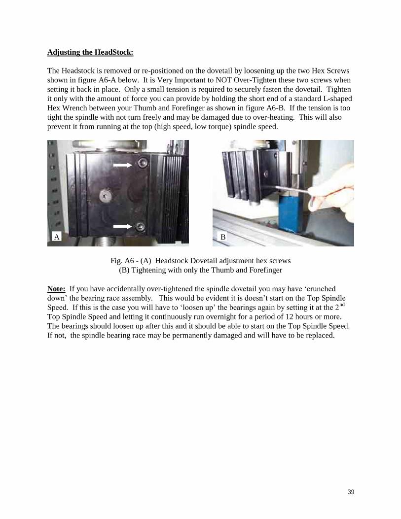
Adjusting the HeadStock:
The Headstock is removed or re-positioned on the dovetail by loosening up the two Hex Screws
shown in figure A6-A below. It is Very Important to NOT Over-Tighten these two screws when
setting it back in place. Only a small tension is required to securely fasten the dovetail. Tighten
it only with the amount of force you can provide by holding the short end of a standard L-shaped
Hex Wrench between your Thumb and Forefinger as shown in figure A6-B. If the tension is too
tight the spindle with not turn freely and may be damaged due to over-heating. This will also
prevent it from running at the top (high speed, low torque) spindle speed.
Fig. A6 - (A) Headstock Dovetail adjustment hex screws
(B) Tightening with only the Thumb and Forefinger
Note: If you have accidentally over-tightened the spindle dovetail you may have ‘crunched
down’ the bearing race assembly. This would be evident it is doesn’t start on the Top Spindle
Speed. If this is the case you will have to ‘loosen up’ the bearings again by setting it at the 2nd
Top Spindle Speed and letting it continuously run overnight for a period of 12 hours or more.
The bearings should loosen up after this and it should be able to start on the Top Spindle Speed.
If not, the spindle bearing race may be permanently damaged and will have to be replaced.
B A
40
SuperCam Program
For MicroMill users that have also selected the SuperCam program option the following
information applies.
SuperCam is a mini Cad/Cam program that allows the user greater flexibility in designing and
machining parts. Please refer to the SuperCam Users Guide for a detailed description of its
operation. To configure SuperCam for the MicroMill the user must initialize the program as
follows:
1. In SuperCam go to the FILES Menu.
2. Select READMCFG.
3. Scroll through the files and select MILLSET1.
4. Click OK to set the configuration.
This should configure a good baseline of the various parameters in SuperCam for running the
MicroMill. The Jog speeds are purposely set a little low to avoid high speed mechanism
jamming. The user can fine tune the parameters from this point in the MCONFIG Sub menu of
the SETUP menu.
If for some reason the parameters are all changed, to the point where the machine is not running
optimally, the user should return to the MCONFIG Sub menu and manually set the most
important parameters as follows:
TRAVEL Speed = 7.5 inch/min
TRAVEL Slew = 15 inch/min
TRAVEL Ramp = 0.0002 inch/min/step
The following limits should be set by clicking on the LIMITS button. The Start Steps/Sec is
probably the most important parameter here and should be selected in the range from 500 to
1000. It should not exceed 1000 as this may cause the stepper motors to stall upon starting a
movement.
Max Steps/Sec = 5000 5000 5000
Start Steps/Sec = 1000 1000 1000
Step Size = 0.000125 0.000125 0.000125
Returning and clicking on DELAYS the user should note that the most important Step Mode
parameter is set to Classic. This is the normal stepping mode that controls the step motor
movement.

41
IMPORTING BOBCAD FILES
Standard BobCad G-code files can be used by the MPS2003 program. The files must be post-
processed with the following procedure and options in BobCad.
1. Generate a BobCad part drawing.
2. Enter the NC-Cam window.
3. In Setup make sure the following parameters are configured (These should just be the
standard default values).
a. Coordinate Values = Absolute
b. Coordinate Output = Non-Modal
c. G-Code = Modal
d. G02 G03 Circular = Incremental I J
e. Circular Movement = Full
f. Spacing = ON
g. Coordinates set to 4 digits
4. Generate the G-Code with the Machine All option.
5. Save the file with the Tape or .TAP option.
This will produce a standard file that can then be imported into the MPS2003 program.
DIGITIZING PROBE OPERATION

42
The Digitizing Probe program MPSPROB3.EXE must be run and is entered with option E from
the main menu. It has the following options.
PROBE PROGRAM:
1 = DIGITIZE
2 = SET PARAMETERS
3 = EXIT
OPTION 1 Start the digitizing process
OPTION 2 Set the digitizing probe parameters
DIGITIZING METHOD = 1
1 = XY RASTER, 2 = XY SPIRAL
METHOD 1 - Figure D1:
The probe moves in the negative Z direction until it makes contact with the material surface. It
then advances along in the positive X direction following the XZ surface profile. When the X
Limit is reached the probe advances in the positive Y direction the Y Raster Distance and
proceeds in the negative X direction. This rastering process continues until the final X Limit and
Y Limit is reached as shown in figure D1.
METHOD 2 - Figure D2:
The probe moves in the negative Z direction until it makes contact with the material surface. It
then proceeds outward from this center point in a square spiral pattern tracing the XZ and YZ
surface as shown in figure D2.
X LIMIT = 2
Sets the maximum X dimension the probe will move to 2 inches.
Y LIMIT = 1
Sets the maximum Y dimension the probe will move to 1 inches. Not used for method 2.
MAX Z DEPTH = -1
Sets the maximum depth the probe will move in the negative Z direction until a surface is
contacted. If this depth is reached without contacting a surface the probe will proceed in the X
direction.
Z TEST DISTANCE = 0.0005

43
Set the Z axis sample distance to 0.0005 inches.
X TEST DISTANCE = 0.01
Sets the distance the X axis advances between contacts to 0.01 inches. For method 2 this is both
the X and Y increment test distance.
X STORE DISTANCE = 0.05
Records the X,Y, and Z coordinates with the X resolution of 0.05 inches. For method 2 the X
STORE DISTANCE = X TEST DISTANCE.
Y RASTER VALUE = 0.05
Set the Y raster or step increment between passes to 0.05 inches. Not used for method 2.
FILE NAME = X.TAP
Save the probe coordinates to the file X.TAP. A file header of G01 F10 is attached to set the file
in linear interpolation mode with a feed rate of 10 Inch/Min.
OPTION 3 Exit the probe program and return to the main menu.
PROBE SETUP and OPERATION:
1. The digitizing probe is installed in the spindle using a 0.25 inch collet as shown in figure D3.
IMPORTANT NOTE - Be sure to unplug the spindle motor so that it is not accidentally
turned on when the probe is in the spindle.
2. Once the probe is installed select option E to enter the Probe Program. Select option 2 to set
the probe parameters. Enter the parameters as prompted. Entering a blank retains the
current value.
3. Exit the Probe program with option 3 and go into Manual Jog mode. If digitizing method 1
was selected jog the probe tip to the lower left corner of the part area you wish to digitize. If
digitizing method 2 was selected jog the probe tip to the center of the part. Be sure the
probe tip is higher then the highest surface of the part to be digitized. Typically the probe is
set about 0.1 to 0.25 inches above this point. Once the tip is positioned exit Manual Jog
mode and Zero all the axes. The part is now ready to be digitized.
4. To view the 3D digitizing process on the screen be sure the PLOT VIEW option V is set to
3D PLOT VIEW and the scan is visible on the screen. For instance if Method 1 or XY
rastering is selected with the X LIMIT = 2 and Y LIMIT = 1 then you should set the X
OFFSET = 1 and Y OFFSET = 0.5 to center it. This is selected with option O from the main
menu. If Method 2 or XY Spiraling is selected just set the X and Y offsets to 0 in general.
44
4. Enter the Probe Program and select 1 to start the digitizing process. You are prompted to
start the digitizing at this point. Hit ENTER to begin or the SPACEBAR to escape. NOTE:
Once option 1 is selected the filename is rewritten.
5. The digitizing process can be HALTED at any time be pressing the SPACEBAR. If pressed
the user is prompted to continue the process by pressing C or stopping it by pressing ENTER.
If ENTER is pressed the digitized points up to that point will remain stored in the chosen
filename.
6. Once the digitizing process is complete the user is prompted to press ENTER to return the
probe back to the home or (0,0,0) point or press the SPACEBAR to stop at the end point. If
ENTER is pressed the following code is appended to the digitized G-Code file.
M0
G0 Z0
M0
X0 Y0
M30
RUNNING THE DIGITIZED PROGRAM:
Once a digitized file has been created it can now be used to machine a duplicate part. The file is
treated like any other normal G-Code file after it is created. The header of G01 F10 is attached
to the top of the file to set it in linear interpolation mode with a default feed rate of 10 Inch/Min.
This can be edited in a standard text editor if needed.
Note: If you wish to machine your part in hard woods or metals you most likely have to take
multiple depth cuts into the material using option 6 from the main program (See SET DEPTH
INC section on page 9). This is because deep profiles are digitized directly in one pass whereby
the machining process must take multiple cuts to reach these depths.

45
Fig. D - Methods of digitizing a surface.
46
LEADSCREW COMPENSATION
The leadscrew on the MicroMill system, like any other machine system, may have slight
variations from the true pitch of the screw. The standard screw pitch is 20 turns/inch for all
three axes on the machine. For the 1.8 deg/step drive motors and half stepping mode employed
by the driver electronics and software this translates to 8000 steps/inch or a step size of 0.000125
inch/step. This is derived as follows:
[ ]Step Size Step Inchv
Inch
Deg
v
Step
Deg
Steps
Inch/
Re
Re .= · · ·=
20 360 2
188000
or taking the inverse,
[ ]Step Size Inch StepInch
Steps
Inch
Step/ .= =
1
80000 000125
If you find that the machine is not moving the proper distance along the lead screw there may be
a slight variation of the screw pitch. In this case you can reprogram the step size to compensate
for the leadscrew pitch error. For example if you program the machine to move 1.000 inches
and measure the actual movement to be 1.001 inches there is a leadscrew error of + 0.001
inch/inch. In this case the true pitch is slightly less than 20 turns/inch. The step size or step/inch
setting would then need to be decreased to compensate for this as follows:
[ ]Step Size Step Inchogrammed Dis ce
True Dis ce
Steps
Inch
Steps
Inch/
Pr tan
tan
.
.= = · =
1000
1001
80007992
This value of 7992 can then be entered as the new step size using the CHANGE UNITS option
from the main menu. Type U and choose option 3 for Custom units. Each axis can then be
reprogrammed with the true step size. Hitting Enter with no value retains the previous value.
Note: This assumes the leadscrew pitch error to change linearly over the length of the screw.
This is typically the type of leadscrew error that occurs, but the error may be a more complex
variation in certain cases. In this case this leadscrew compensation technique will not
completely eliminate the inherent pitch error.

47
SPEEDS AND FEEDS FOR DRILLING
DRILLING SPEEDS (HIGH SPEED STEEL DRILLS):
Material Average Drill Speed (sfm) Magnesium
Alaaa
300
s Aluminum 250
Brass and Bronze 200
Copper
as
70
Cast Iron (soft) 120
Cast Iron (hard) 80
Mild Steel 110
Cast Steel 50
Alloy Steels (hard) 60
Tool Steel 60
Stainless Steel 30
Titanium 30
High Manganese Steel 15
Note: For carbide drills, double the average speeds.
DRILLING FEEDS:
Drill Diameter (inch) Drill Feed (ipr)
< 1/8 0.001 - 0.002
1/8 - 1/4 0.002 - 0.004
1/4 - 1/2 0.004 - 0.007
1/2 - 1 0.007 - 0.015
> 1 0.015 - 0.025
Note: Use a slightly lower feed when drilling hard materials such as carbon steel,
tool steel, or stainless steel. Use a slightly higher feed when drilling softer materials
such as magnesium, aluminum, or soft cast iron.
48
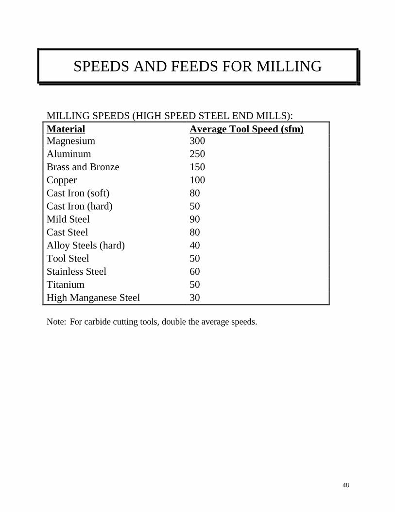
SPEEDS AND FEEDS FOR MILLING
MILLING SPEEDS (HIGH SPEED STEEL END MILLS):
Material Average Tool Speed (sfm) Magnesium
Alaaa
300
s Aluminum 250
Brass and Bronze 150
Copper
as
100
Cast Iron (soft) 80
Cast Iron (hard) 50
Mild Steel 90
Cast Steel 80
Alloy Steels (hard) 40
Tool Steel 50
Stainless Steel 60
Titanium 50
High Manganese Steel 30
Note: For carbide cutting tools, double the average speeds.
49
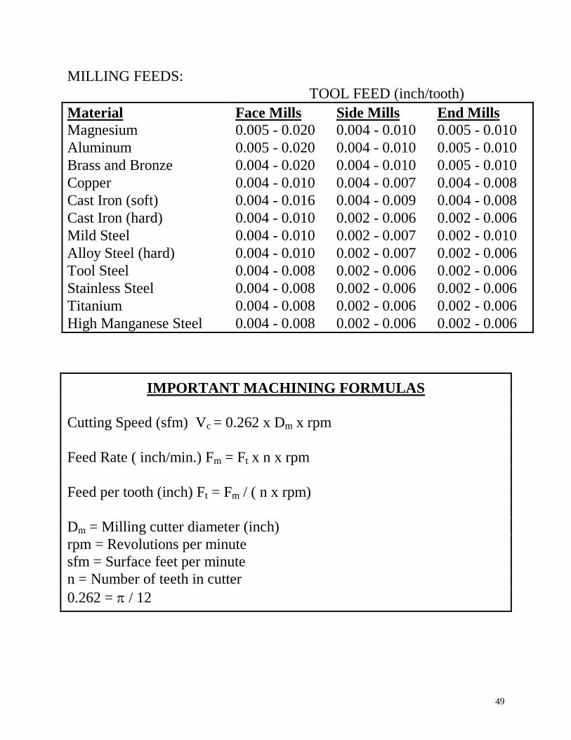
MILLING FEEDS:
TOOL FEED (inch/tooth)
Material Face Mills Side Mills End Mills
Magnesium 0.005 - 0.020 0.004 - 0.010 0.005 - 0.010
Aluminum 0.005 - 0.020 0.004 - 0.010 0.005 - 0.010
Brass and Bronze 0.004 - 0.020 0.004 - 0.010 0.005 - 0.010
Copper 0.004 - 0.010 0.004 - 0.007 0.004 - 0.008
Cast Iron (soft) 0.004 - 0.016 0.004 - 0.009 0.004 - 0.008
Cast Iron (hard) 0.004 - 0.010 0.002 - 0.006 0.002 - 0.006
Mild Steel 0.004 - 0.010 0.002 - 0.007 0.002 - 0.010
Alloy Steel (hard) 0.004 - 0.010 0.002 - 0.007 0.002 - 0.006
Tool Steel 0.004 - 0.008 0.002 - 0.006 0.002 - 0.006
Stainless Steel 0.004 - 0.008 0.002 - 0.006 0.002 - 0.006
Titanium 0.004 - 0.008 0.002 - 0.006 0.002 - 0.006
High Manganese Steel 0.004 - 0.008 0.002 - 0.006 0.002 - 0.006
IMPORTANT MACHINING FORMULAS
Cutting Speed (sfm) Vc = 0.262 x Dm x rpm
Feed Rate ( inch/min.) Fm = Ft x n x rpm
Feed per tooth (inch) Ft = Fm / ( n x rpm)
Dm = Milling cutter diameter (inch)
rpm = Revolutions per minute
sfm = Surface feet per minute
n = Number of teeth in cutter
0.262 = / 12


