
Designing the VCNL4035X01 Into an Application - Vishay · Designing the VCNL4035X01 Into an...
26
VISHAY SEMICONDUCTORS Optical Sensors Application Note Designing the VCNL4035X01 Into an Application www.vishay.com Revision: 25-Apr-2018 1 Document Number: 84417 For technical questions, contact: [email protected] THIS DOCUMENT IS SUBJECT TO CHANGE WITHOUT NOTICE. THE PRODUCTS DESCRIBED HEREIN AND THIS DOCUMENT ARE SUBJECT TO SPECIFIC DISCLAIMERS, SET FORTH AT www.vishay.com/doc?91000 APPLICATION NOTE By Reinhard Schaar INTRODUCTION AND BASIC OPERATION The VCNL4035X01 is a fully integrated gesture, proximity, and ambient light sensor with a built-in switch for three external emitters and gesture functionality. It combines a photodiode for proximity measurement, an ambient light sensor, and signal processing IC in a single package with two 16-bit ADCs. The device provides ambient light sensing to support conventional backlight and display brightness auto-adjustment, and proximity sensing to minimize accidental touch input that can lead to call drops and camera launch. The IRED driver supports switching up to three external emitters via a dedicated register. This allows simple left / right gestures as well as up / down gestures or direction detection. With a range of up to 40 cm (16"), this component greatly simplifies the use and design-in of a proximity sensor in consumer and industrial applications, adding one or up to three emitters to the sensor. The VCNL4035X01 features a miniature, surface-mount 4.0 mm by 2.36 mm leadless package (LLP) with a low profile of 0.75 mm. The device is designed specifically to meet the low height requirements of smartphone, mobile phone, digital camera, and tablet PC applications. Through its standard I 2 C bus serial digital interface, it allows easy access to “proximity signal” and “light intensity” measurements. The programmable interrupt function offers wake-up functionality for the microcontroller when a proximity event or ambient light change occurs, which reduces processing overhead by eliminating the need for continuous polling. Fig. 1 - VCNL4035X01 Top View COMPONENTS (BLOCK DIAGRAM) The major components of the VCNL4035X01 are shown in the block diagram. In addition to the ASIC with the ambient light and proximity photodiode, the “switch” for up to three external emitters is also implemented. Fig. 2 - VCNL4035X01 Detailed Block Diagram The external infrared emitter(s) should come with a peak wavelength between 850 nm and 940 nm to fit to the peak sensitivity of the proximity photodiode. The ASIC has a programmable drive current from 50 mA to 200 mA in eight steps. The infrared light is emitted in short pulses with a programmable duty ratio from 1/40 to 1/320. The proximity photodiode receives the light that is reflected off the object and converts it to a current. It has a peak sensitivity of 850 nm. The sensitivity of the proximity stage is also programmable by choosing from eight different integration times. It is insensitive to ambient light. It filters out the DC component of light and compensates even for strong sunlight. 1 V DD 2 SCL 3 GND 4 IRED3 8 7 5 6 SDA INT IRED1 IRED2 PS-PD ALS- PD VCNL4035X01 Temperature sensor Output buffer I 2 C interface PS data buffer ALS 16-bit data buffer Low pass filter DSP Oscillator Drivers
Transcript of Designing the VCNL4035X01 Into an Application - Vishay · Designing the VCNL4035X01 Into an...

V I S H A Y S E M I C O N D U C T O R S
Optical Sensors Application Note
Designing the VCNL4035X01 Into an Application
www.vishay.com
Revision: 25-Apr-2018 1 Document Number: 84417For technical questions, contact: [email protected]
THIS DOCUMENT IS SUBJECT TO CHANGE WITHOUT NOTICE. THE PRODUCTS DESCRIBED HEREIN AND THIS DOCUMENTARE SUBJECT TO SPECIFIC DISCLAIMERS, SET FORTH AT www.vishay.com/doc?91000
AP
PL
ICA
TIO
N N
OT
E
By Reinhard Schaar
INTRODUCTION AND BASIC OPERATIONThe VCNL4035X01 is a fully integrated gesture, proximity, and ambient light sensor with a built-in switch for three external emitters and gesture functionality. It combines a photodiode for proximity measurement, an ambient light sensor, and signal processing IC in a single package with two 16-bit ADCs. The device provides ambient light sensing to support conventional backlight and display brightness auto-adjustment, and proximity sensing to minimize accidental touch input that can lead to call drops and camera launch. The IRED driver supports switching up to three external emitters via a dedicated register. This allows simple left / right gestures as well as up / down gestures or direction detection.
With a range of up to 40 cm (16"), this component greatly simplifies the use and design-in of a proximity sensor in consumer and industrial applications, adding one or up to three emitters to the sensor. The VCNL4035X01 features a miniature, surface-mount 4.0 mm by 2.36 mm leadless package (LLP) with a low profile of 0.75 mm. The device is designed specifically to meet the low height requirements of smartphone, mobile phone, digital camera, and tablet PC applications.
Through its standard I2C bus serial digital interface, it allows easy access to “proximity signal” and “light intensity” measurements. The programmable interrupt function offers wake-up functionality for the microcontroller when a proximity event or ambient light change occurs, which reduces processing overhead by eliminating the need for continuous polling.
Fig. 1 - VCNL4035X01 Top View
COMPONENTS (BLOCK DIAGRAM)The major components of the VCNL4035X01 are shown in the block diagram.
In addition to the ASIC with the ambient light and proximity photodiode, the “switch” for up to three external emitters is also implemented.
Fig. 2 - VCNL4035X01 Detailed Block Diagram
The external infrared emitter(s) should come with a peak wavelength between 850 nm and 940 nm to fit to the peak sensitivity of the proximity photodiode.
The ASIC has a programmable drive current from 50 mA to 200 mA in eight steps. The infrared light is emitted in short pulses with a programmable duty ratio from 1/40 to 1/320. The proximity photodiode receives the light that is reflected off the object and converts it to a current. It has a peak sensitivity of 850 nm. The sensitivity of the proximity stage is also programmable by choosing from eight different integration times. It is insensitive to ambient light. It filters out the DC component of light and compensates even for strong sunlight.
1VDD
2SCL
3GND
4IRED3
8
7
5
6
SDA
INT
IRED1
IRED2
PS
-PD
ALS
-PD
VCNL4035X01
Temperaturesensor
Out
put
buf
fer
I2 C in
terf
ace
PSdata buffer
ALS 16-bitdata buffer
Low passfilter
DSP
Osc
illat
orDrivers
Designing the VCNL4035X01 Into an Application
Application Notewww.vishay.com Vishay Semiconductors
AP
PL
ICA
TIO
N N
OT
E
Revision: 25-Apr-2018 2 Document Number: 84417For technical questions, contact: [email protected]
THIS DOCUMENT IS SUBJECT TO CHANGE WITHOUT NOTICE. THE PRODUCTS DESCRIBED HEREIN AND THIS DOCUMENTARE SUBJECT TO SPECIFIC DISCLAIMERS, SET FORTH AT www.vishay.com/doc?91000
The ambient light sensor receives the visible light and converts it to a current. The human eye can see light with wavelengths from 380 nm to 780 nm, with a peak of 555 nm. Vishay’s ambient light sensor closely matches this range of sensitivity. It has peak sensitivity at 540 nm and a bandwidth from 430 nm to 610 nm.
The application-specific integrated circuit, or ASIC, includes an LED driver, I2C bus interface, amplifier, integrated analog-to-digital converter, oscillator, and Vishay’s “secret sauce” signal processor. For proximity, it converts the current from the photodiode to a 12-bit or 16-bit digital data output value. For ambient light sensing, it converts the current from the ambient light detector, amplifies it, and converts it to a 16-bit digital output stream.
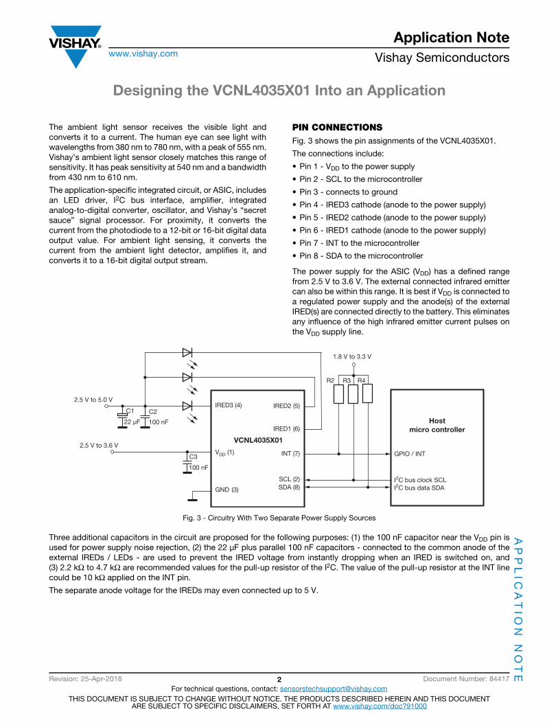
PIN CONNECTIONSFig. 3 shows the pin assignments of the VCNL4035X01.
The connections include:
• Pin 1 - VDD to the power supply
• Pin 2 - SCL to the microcontroller
• Pin 3 - connects to ground
• Pin 4 - IRED3 cathode (anode to the power supply)
• Pin 5 - IRED2 cathode (anode to the power supply)
• Pin 6 - IRED1 cathode (anode to the power supply)
• Pin 7 - INT to the microcontroller
• Pin 8 - SDA to the microcontroller
The power supply for the ASIC (VDD) has a defined range from 2.5 V to 3.6 V. The external connected infrared emitter can also be within this range. It is best if VDD is connected to a regulated power supply and the anode(s) of the external IRED(s) are connected directly to the battery. This eliminates any influence of the high infrared emitter current pulses on the VDD supply line.
Fig. 3 - Circuitry With Two Separate Power Supply Sources
Three additional capacitors in the circuit are proposed for the following purposes: (1) the 100 nF capacitor near the VDD pin is used for power supply noise rejection, (2) the 22 μF plus parallel 100 nF capacitors - connected to the common anode of the external IREDs / LEDs - are used to prevent the IRED voltage from instantly dropping when an IRED is switched on, and (3) 2.2 kΩ to 4.7 kΩ are recommended values for the pull-up resistor of the I2C. The value of the pull-up resistor at the INT line could be 10 kΩ applied on the INT pin.
The separate anode voltage for the IREDs may even connected up to 5 V.
GND (3)
VDD (1)
IRED3 (4)C1 C2
C3
100 nF
100 nF
22 μF
2.5 V to 5.0 V
1.8 V to 3.3 V
R2 R3 R4
IRED2 (5)
IRED1 (6)
INT (7)
SCL (2)SDA (8)
I2C bus clock SCLI2C bus data SDA
GPIO / INT
Host
micro controller
VCNL4035X012.5 V to 3.6 V

Designing the VCNL4035X01 Into an Application
Application Notewww.vishay.com Vishay Semiconductors
AP
PL
ICA
TIO
N N
OT
E
Revision: 25-Apr-2018 3 Document Number: 84417For technical questions, contact: [email protected]
THIS DOCUMENT IS SUBJECT TO CHANGE WITHOUT NOTICE. THE PRODUCTS DESCRIBED HEREIN AND THIS DOCUMENTARE SUBJECT TO SPECIFIC DISCLAIMERS, SET FORTH AT www.vishay.com/doc?91000
Fig. 4 - Circuitry With Just One Common Power Supply Source
For high currents of the IREDs and / or power supply close to the lower limit of 2.5 V, this R-C decoupling will prevent the VDDvoltage drop below a specified minimum.
The IREDs should come with a peak wavelength between 850 nm and 940 nm to fit to the sensitivity of the proximity photodiode.
Mechanical placement of the external IRED depends on the application.
MECHANICAL DESIGN CONSIDERATIONSThe VCNL4035X01 is a gesture, proximity, and ambient light sensor. The number and exact positioning of the external IREDs depend on the needs of the specific application. Distances between the IRED and sensor may be just a few millimeters if simply the proximity of an object needs to be seen or small gestures like a shift of a finger needs to be detected. If the swipe of a hand at further distances needs to be seen and its direction should be detected, a wider distance between the sensor and the IREDs offers advantages.
The VCNL4035X01 does not require a mechanical barrier. IREDs placed close to the sensor will show crosstalk that will lead to an increase of so-called offset counts, but reflection from the cover may add even more. These total offset counts are fixed and can even be subtracted directly on-chip using the so-called “cancellation” register. Here the overall measured counts can be written in and are set to zero.
The only dimensions that the design engineer needs to consider are the distance from the top surface of the sensor to the outside surface of the window, and the size of the window. These dimensions will determine the size of the detection zone.
The sensitivity of the photodiodes shows an angle of half sensitivity of about ± 55°.
Fig. 5 - Angle of the Half Sensitivity of the Photodiode
GND (3)
VDD (1)
IRED3 (4)C1 C2
C3C4
R1
100 nF
100 nF10 μF
22 μF
10R
2.5 V to 3.6 V
1.8 V to 3.3 V
R2 R3 R4
IRED2 (5)
IRED1 (6)
INT (7)
SCL (2)SDA (8)
I2C bus clock SCLI2C bus data SDA
GPIO / INT
Host
micro controller
VCNL4035X01
0° 20°
40°
60°
80°
0.6
0.7
0.8
0.9
1.0
00.10.20.30.40.5
Sre
l - R
elat
ive S
ensi
tivity
ϕ -
Ang
ular
Dis
plac
emen
t

Designing the VCNL4035X01 Into an Application
Application Notewww.vishay.com Vishay Semiconductors
AP
PL
ICA
TIO
N N
OT
E
Revision: 25-Apr-2018 4 Document Number: 84417For technical questions, contact: [email protected]
THIS DOCUMENT IS SUBJECT TO CHANGE WITHOUT NOTICE. THE PRODUCTS DESCRIBED HEREIN AND THIS DOCUMENTARE SUBJECT TO SPECIFIC DISCLAIMERS, SET FORTH AT www.vishay.com/doc?91000
Fig. 6 - Proposal Angle of Relative Radiant Sensitivity
To achieve a good ambient light response, the diameter of the hole within the cover glass should not be too small. An angle of ± 40° will be sufficient in most applications. The package drawing shows the position of the photosensitive area. The 40° lines should be set at the sides of the opening. The following are dimensions for the distance from the top surface of the sensor to the outside surface of the glass (a) and the width of the window (d).
For a single round hole, the diameter should be at least wide enough so that the openings can freely look through; so, about 1.2 mm if the cover is directly on top of the sensor: a = 0 mm.
Fig. 7 - Light Hole Diameter(in millimeters)
The diameter needs to be increased with the distances between the sensor and cover glass according to the following calculation.
Fig. 8 - Window Dimensions for One Hole (in millimeters)
The width calculation for distances from 0 mm to 3 mm results in:
a = 0.0 mm → x = 0.00 mm → d = 1.2 mm + 0.00 mm = 1.20 mm a = 0.5 mm → x = 0.42 mm → d = 1.2 mm + 0.84 mm = 2.04 mm a = 1.0 mm → x = 0.84 mm → d = 1.2 mm + 1.68 mm = 2.88 mm a = 1.5 mm → x = 1.28 mm → d = 1.2 mm + 2.56 mm = 3.76 mm a = 2.0 mm → x = 1.68 mm → d = 1.2 mm + 3.36 mm = 4.56 mm a = 2.5 mm → x = 2.10 mm → d = 1.2 mm + 4.20 mm = 5.40 mm a = 3.0 mm → x = 2.52 mm → d = 1.2 mm + 5.04 mm = 6.24 mm
40°
60°
80°
0.6
0.7
0.8
0.9
1.0
Sre
l - R
elat
ive S
ensi
tivity
ϕ -
Ang
ular
Dis
plac
emen
t
40°0°
α = ± 40°
0.78
0.8
3.145
d = 1.13
α
x
0.75
d
a

Designing the VCNL4035X01 Into an Application
Application Notewww.vishay.com Vishay Semiconductors
AP
PL
ICA
TIO
N N
OT
E
Revision: 25-Apr-2018 5 Document Number: 84417For technical questions, contact: [email protected]
THIS DOCUMENT IS SUBJECT TO CHANGE WITHOUT NOTICE. THE PRODUCTS DESCRIBED HEREIN AND THIS DOCUMENTARE SUBJECT TO SPECIFIC DISCLAIMERS, SET FORTH AT www.vishay.com/doc?91000
PROXIMITY SENSORThe main DC light sources found in the environment are sunlight and tungsten (incandescent) bulbs. These kinds of disturbance sources will cause a DC current in the detector inside the sensor, which in turn will produce noise in the receiver circuit. The negative influence of this DC light can be reduced by optical filtering, but is reduced much more efficiently by a so-called DC kill function. The proximity photodiode shows its best sensitivity at about 850 nm, as shown in Fig. 10.
Fig. 9 - Normalized Spectral Response(ALS channel)
Fig. 10 - Normalized Spectral Response(PS channel)
The proximity sensor uses a short pulse signal of about 50 μs (PS_IT = 1T) up to 400 μs (PS_IT = 8T). The on / off duty ratio setting now defines which repetition rate to be used, which can be programmed from 1/40 up to 1/320.
In addition to DC light source noise, there is some reflection of the infrared emitted light off the surfaces of the components surrounding the VCNL4035X01. The distance to the cover, proximity of surrounding components, tolerances of the sensor, defined infrared emitter current, ambient temperature, and type of window material used all contribute to this reflection. The result of the reflection and DC noise is the production of an output current on the proximity and light sensing photodiode. This current is converted into a count called the offset count.
In addition to the offset count, there could also be a small noise floor during the proximity measurement, which comes from the DC light suppression circuitry. This noise is typically just one or two counts. Only with light sources with strong infrared content could it be in the range from ± 5 counts to ± 10 counts.
The application should “ignore” this offset and small noise floor by subtracting them from the total proximity readings. The VCNL4035X01 offers a subtraction feature that automatically does this: PS_CANC. During the development of the end product, this offset count is evaluated and may be written into register 5: PS_CANC_L/M. Now the proximity output data will just show the subtraction result of proximity counts - offset counts.
Results most often do not need to be averaged. If an object with very low reflectivity or at longer range needs to be detected, the sensor provides a register where you can define the number of consecutive measurements that the signal must exceed before producing an interrupt. This provides stable results without requiring averaging.
10
100
1000
10000
400 500 600 700 800 900 1000
Axis Title
1st
line
2nd
line
2nd
line
Nor
mal
ized
Out
put
(%
)
λ - Wavelength (nm)2nd line
Human eye
0
20
40
60
80
100
120
ALS
10
100
1000
10000
550 600 650 700 800 900 1000
Axis Title
1st
line
2nd
line
2nd
line
Nor
mal
ized
Out
put
(%
)
λ - Wavelength (nm)2nd line
0
20
40
60
80
100
120
750 850 950
Designing the VCNL4035X01 Into an Application
Application Notewww.vishay.com Vishay Semiconductors
AP
PL
ICA
TIO
N N
OT
E
Revision: 25-Apr-2018 6 Document Number: 84417For technical questions, contact: [email protected]
THIS DOCUMENT IS SUBJECT TO CHANGE WITHOUT NOTICE. THE PRODUCTS DESCRIBED HEREIN AND THIS DOCUMENTARE SUBJECT TO SPECIFIC DISCLAIMERS, SET FORTH AT www.vishay.com/doc?91000
PROXIMITY CURRENT CONSUMPTIONBoth the ambient light sensor (ALS) and the proximity sensor (PS) within the VCNL4035X01 offer a separate shutdown mode. Default values after start-up have them both disabled. The application may activate just the one wanted or both.
The VCNL4035X01’s embedded LED driver drives the external IRED(s) with a pulsed duty cycle. The IRED on / off duty ratio is programmable by an I2C command at register PS_Duty. Depending on this pulse / pause ratio, the overall proximity current consumption can be calculated. When a higher measurement speed or faster response time is needed, PS_Duty may be selected to a maximum value of 1/40, which means one measurement will be made every 2 ms, but this will then also lead to the highest current consumption:
PS_Duty = 1/40: peak IRED current = 100 mA, averaged current consumption is 100 mA/40 = 2.5 mA.
For proximity measurements executed just every 40 ms: PS_Duty = 1/320 peak IRED current = 100 mA, averaged current consumption is 100 mA/320 = 0.3125 mA.
The above is always valid for the normal pulse width of T = 1T = 50 μs, as well as for 2T, 4T, 8T, and all others in between. These pulse lengths are always doubled, resulting in 400 μs for 8T, but the repetition time is also doubled, ending in a period time of about 128 ms.
An extremely power-efficient way to execute proximity measurements is to apply a PS active force mode (register: PS_CONF3, command: PS_AF = 1).
If only a single proximity measurement needs to be done, PS_AF is set to “1” and then PS_SD = 0 = active. Setting PS_Trig = 1 will then execute just one single measurement.
In this mode, only the I2C interface is active. In most consumer electronic applications the sensor will spend the majority of time in sleep mode; it only needs to be woken up for a proximity or light measurement. In standby mode the power consumption is about 0.2 μA.
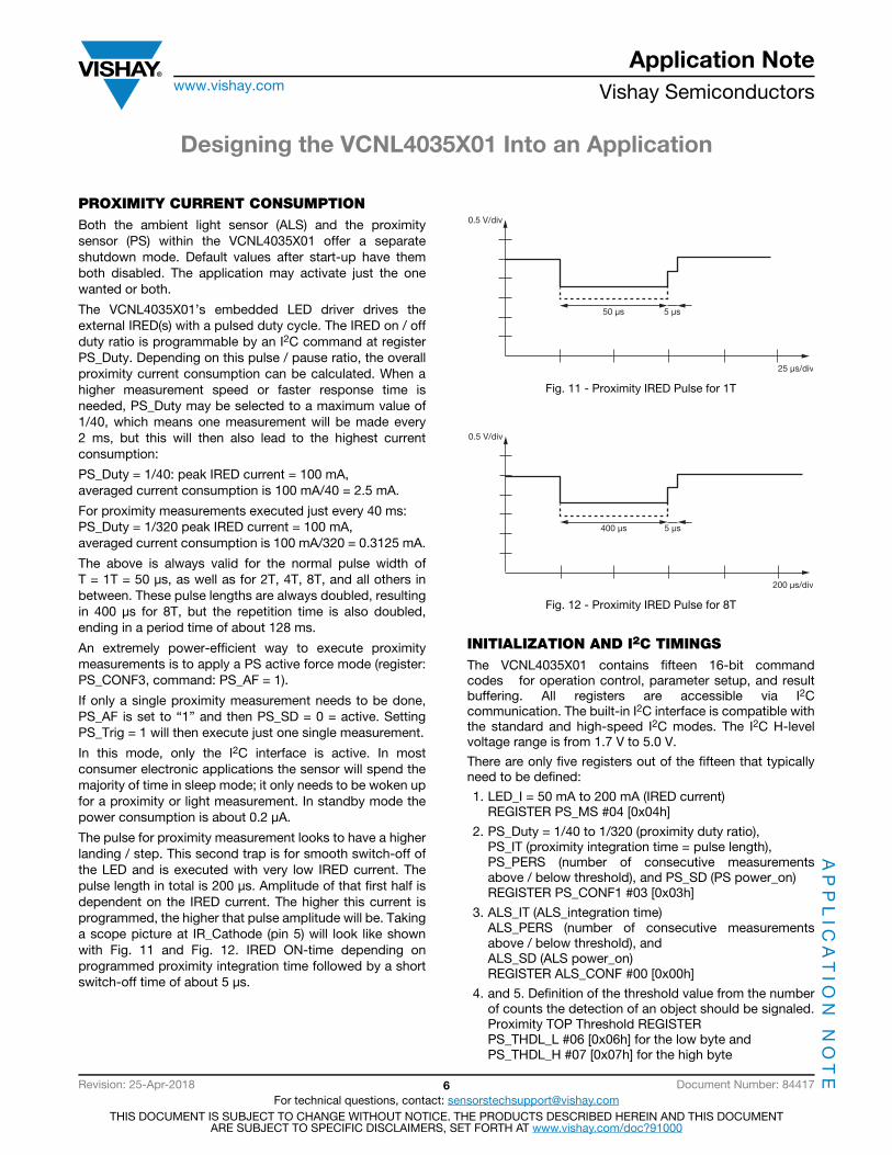
The pulse for proximity measurement looks to have a higher landing / step. This second trap is for smooth switch-off of the LED and is executed with very low IRED current. The pulse length in total is 200 μs. Amplitude of that first half is dependent on the IRED current. The higher this current is programmed, the higher that pulse amplitude will be. Taking a scope picture at IR_Cathode (pin 5) will look like shown with Fig. 11 and Fig. 12. IRED ON-time depending on programmed proximity integration time followed by a short switch-off time of about 5 μs.
Fig. 11 - Proximity IRED Pulse for 1T
Fig. 12 - Proximity IRED Pulse for 8T
INITIALIZATION AND I2C TIMINGSThe VCNL4035X01 contains fifteen 16-bit command codes for operation control, parameter setup, and result buffering. All registers are accessible via I2C communication. The built-in I2C interface is compatible with the standard and high-speed I2C modes. The I2C H-level voltage range is from 1.7 V to 5.0 V.
There are only five registers out of the fifteen that typically need to be defined:
1. LED_I = 50 mA to 200 mA (IRED current) REGISTER PS_MS #04 [0x04h]
2. PS_Duty = 1/40 to 1/320 (proximity duty ratio), PS_IT (proximity integration time = pulse length), PS_PERS (number of consecutive measurements above / below threshold), and PS_SD (PS power_on) REGISTER PS_CONF1 #03 [0x03h]
3. ALS_IT (ALS_integration time) ALS_PERS (number of consecutive measurements above / below threshold), and ALS_SD (ALS power_on) REGISTER ALS_CONF #00 [0x00h]
4. and 5. Definition of the threshold value from the number of counts the detection of an object should be signaled. Proximity TOP Threshold REGISTER PS_THDL_L #06 [0x06h] for the low byte and PS_THDL_H #07 [0x07h] for the high byte
25 μs/div
0.5 V/div
50 μs 5 μs
0.5 V/div
400 μs 5 μs
200 μs/div

Designing the VCNL4035X01 Into an Application
Application Notewww.vishay.com Vishay Semiconductors
AP
PL
ICA
TIO
N N
OT
E
Revision: 25-Apr-2018 7 Document Number: 84417For technical questions, contact: [email protected]
THIS DOCUMENT IS SUBJECT TO CHANGE WITHOUT NOTICE. THE PRODUCTS DESCRIBED HEREIN AND THIS DOCUMENTARE SUBJECT TO SPECIFIC DISCLAIMERS, SET FORTH AT www.vishay.com/doc?91000
To define the infrared emitter current, as well as the integration time (length of the proximity pulsing), evaluation tests should be performed using the least reflective material at the maximum distance specified.
Fig. 13 shows the typical digital counts output versus distance that are seen using the VSMY2940 as the emitter placed about 20 mm away from the sensor and operated with max. IRED current of 200 mA and highest proximity integration time of 400 μs. Here the so-called “two step” mode is used, and with PS_NS = 0 a four times higher gain is programmed. The reflective reference medium is the Kodak Gray card. This card shows approximately 18 % reflectivity at 940 nm.
Fig. 13 - Proximity Value vs. Distance for 8T and 200 mA
This diagram shows the possible detection counts with a short pulse of 400 μs and so-called “two step” mode. Another mode is the “single mode”. This may show an advantage if the sensor also needs to be used under strong sunlight conditions and for long distances where only few detection counts will be seen. This “single mode” is available with two different sensitivities, where “single mode x 1” delivers higher gain and best compensation for disturbing light sources and for strong sunlight. In addition, the compensation current can be modified with PS_SC-CUR in four possible steps from “typical” up to eight times this typical current.
To define for this “sunlight cancellation” the bit PS_SC_EN has to be set. The bit PS_SP also enhances the sunlight cancellation capability by 50 %, typically. The bit PS_SPO defines the counts that should be presented if too strong sun light causes protection, either zero counts or max. counts, 65 535 in 16-bit mode.
In order to reach the high reflection counts of the Kodak Gray card, one has to define the proximity range to 16 bit, otherwise the 12-bit range would just lead to 4095 counts. This is possible to select with: PS_HD = 1 within PS_CONF2 byte of command code #3.
The duty time (PS_Duty) is defined as the repetition rate or the number of proximity measurements per second (speed of proximity measurements). This is possible between 2 ms (about 500 measurements/s) by programming PS_Duty with 1/40 and 16 ms (about 62 measurements/s) with programming PS_Duty with 1/320.
Fig. 14 - Proximity Measurements With PS_Duty = 1/40
Fig. 15 - Proximity Measurements With PS_Duty = 1/320
This duty cycle also determines how fast the application reacts when an object appears in, or is removed from, the proximity zone.
Reaction time is also determined by the number of counts that must be exceeded before an interrupt is set. This is possible to define with proximity persist: PS_PERS. Possible values are from 1 to 4.
To define all these register values, an evaluation test should be performed.
10
100
1000
10000
1
10
100
1000
100 000
0.1 1 10 100 1000
Axis Title1s
t lin
e2n
d li
ne
1st
line
2nd line
Pro
xim
ity V
alue
(cou
nts)
Distance to Reflecting Card (mm)
Kodak gray card
10 000Kodak
white card
1T and 1/40 � 2 ms
2T and 1/320 � 32 ms
Designing the VCNL4035X01 Into an Application
Application Notewww.vishay.com Vishay Semiconductors
AP
PL
ICA
TIO
N N
OT
E
Revision: 25-Apr-2018 8 Document Number: 84417For technical questions, contact: [email protected]
THIS DOCUMENT IS SUBJECT TO CHANGE WITHOUT NOTICE. THE PRODUCTS DESCRIBED HEREIN AND THIS DOCUMENTARE SUBJECT TO SPECIFIC DISCLAIMERS, SET FORTH AT www.vishay.com/doc?91000
Timing
For an I2C bus operating at 100 kHz, to write or read an 8-bit byte, plus start (or stop) and bit acknowledgement, takes 100 μs. Together with the slave address byte and the 8-bit command code byte, plus the 16-bit data, this results in a total of 400 μs. When the device is powered on, the initialization with just these five registers needs 5 x 4 bytes (slave address, command register, and 16-bit data) for a total of 20 bytes. So, 20 x 100 μs = 2000 μs = 2 ms.
The read-out of 16-bit data would take a total of five bytes (slave address, command code, slave address with read bit set) and 16-bit data sent from the VCNL4035X01. So, 500 μs:
Power Up
The release of the internal reset, the start of the oscillator, and the signal processor need 2.5 ms
Initialize Registers
Write to four registers 1600 μs
- IRED current- Proximity duty ratio- ALS integration time- Proximity interrupt TOP threshold
Once the device is powered on and the VCNL4035X01 is initialized, a proximity measurement can be taken.
Fig. 16 - Timing Specification for Active Forced Mode
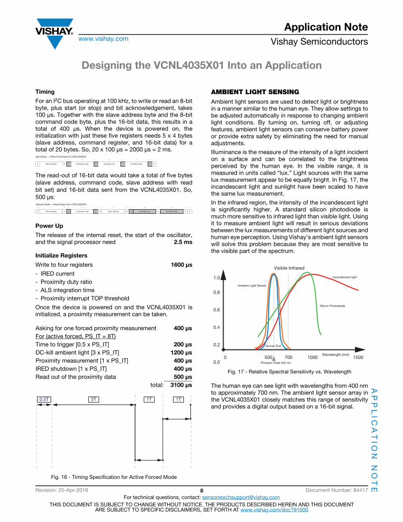
AMBIENT LIGHT SENSINGAmbient light sensors are used to detect light or brightness in a manner similar to the human eye. They allow settings to be adjusted automatically in response to changing ambient light conditions. By turning on, turning off, or adjusting features, ambient light sensors can conserve battery power or provide extra safety by eliminating the need for manual adjustments.
Illuminance is the measure of the intensity of a light incident on a surface and can be correlated to the brightness perceived by the human eye. In the visible range, it is measured in units called “lux.” Light sources with the same lux measurement appear to be equally bright. In Fig. 17, the incandescent light and sunlight have been scaled to have the same lux measurement.
In the infrared region, the intensity of the incandescent light is significantly higher. A standard silicon photodiode is much more sensitive to infrared light than visible light. Using it to measure ambient light will result in serious deviations between the lux measurements of different light sources and human eye perception. Using Vishay’s ambient light sensors will solve this problem because they are most sensitive to the visible part of the spectrum.
Fig. 17 - Relative Spectral Sensitivity vs. Wavelength
The human eye can see light with wavelengths from 400 nm to approximately 700 nm. The ambient light sensor array in the VCNL4035X01 closely matches this range of sensitivity and provides a digital output based on a 16-bit signal.
Asking for one forced proximity measurement 400 μs
For (active forced, PS_IT = 8T)Time to trigger [0.5 x PS_IT] 200 μs
DC-kill ambient light [3 x PS_IT] 1200 μs
Proximity measurement [1 x PS_IT] 400 μs
IRED shutdown [1 x PS_IT] 400 μs
Read out of the proximity data 500 μs
total: 3100 μs
S Slave Address Wr A Command Code A Data Byte Low A Data Byte High A
1 7 81 1 1 8 1 8
P
1 1
Send Byte → Write Command to VCNL4035X01
1
Slave Address
7
Wr A Command Code A S Slave Address Rd A Data Byte Low A Data Byte High A P
1 1 8 1 1 7 1 1 8 1 8 1 1
S
Receive Byte → Read Data from VCNL4035X01
0.5T 3T 1T 1T
Photopic Peak 550 nm
Human Eye
Ambient Light Sensor
Silicon Photodiode
Incandescent light
Wavelength (nm)
Visible Infrared
1.0
0.8
0.6
0.4
0.2
0.00 500 700 1000 1500
Designing the VCNL4035X01 Into an Application
Application Notewww.vishay.com Vishay Semiconductors
AP
PL
ICA
TIO
N N
OT
E
Revision: 25-Apr-2018 9 Document Number: 84417For technical questions, contact: [email protected]
THIS DOCUMENT IS SUBJECT TO CHANGE WITHOUT NOTICE. THE PRODUCTS DESCRIBED HEREIN AND THIS DOCUMENTARE SUBJECT TO SPECIFIC DISCLAIMERS, SET FORTH AT www.vishay.com/doc?91000
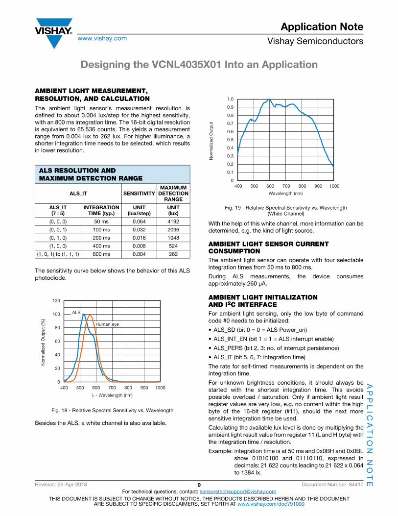
AMBIENT LIGHT MEASUREMENT, RESOLUTION, AND CALCULATIONThe ambient light sensor’s measurement resolution is defined to about 0.004 lux/step for the highest sensitivity, with an 800 ms integration time. The 16-bit digital resolution is equivalent to 65 536 counts. This yields a measurement range from 0.004 lux to 262 lux. For higher illuminance, a shorter integration time needs to be selected, which results in lower resolution.
The sensitivity curve below shows the behavior of this ALS photodiode.
Fig. 18 - Relative Spectral Sensitivity vs. Wavelength
Besides the ALS, a white channel is also available.
Fig. 19 - Relative Spectral Sensitivity vs. Wavelength(White Channel)
With the help of this white channel, more information can be determined, e.g. the kind of light source.
AMBIENT LIGHT SENSOR CURRENT CONSUMPTIONThe ambient light sensor can operate with four selectable integration times from 50 ms to 800 ms.
During ALS measurements, the device consumes approximately 260 μA.
AMBIENT LIGHT INITIALIZATION AND I2C INTERFACEFor ambient light sensing, only the low byte of command code #0 needs to be initialized:
• ALS_SD (bit 0 = 0 = ALS Power_on)
• ALS_INT_EN (bit 1 = 1 = ALS interrupt enable)
• ALS_PERS (bit 2, 3: no. of interrupt persistence)
• ALS_IT (bit 5, 6, 7: integration time)
The rate for self-timed measurements is dependent on the integration time.
For unknown brightness conditions, it should always be started with the shortest integration time. This avoids possible overload / saturation. Only if ambient light result register values are very low, e.g. no content within the high byte of the 16-bit register (#11), should the next more sensitive integration time be used.
Calculating the available lux level is done by multiplying the ambient light result value from register 11 (L and H byte) with the integration time / resolution.
Example: integration time is at 50 ms and 0x0BH and 0x0BL show 01010100 and 01110110, expressed in decimals: 21 622 counts leading to 21 622 x 0.064 to 1384 lx.
ALS RESOLUTION AND MAXIMUM DETECTION RANGE
ALS_IT SENSITIVITYMAXIMUM
DETECTIONRANGE
ALS_IT(7 : 5)
INTEGRATIONTIME (typ.)
UNIT(lux/step)
UNIT(lux)
(0, 0, 0) 50 ms 0.064 4192
(0, 0, 1) 100 ms 0.032 2096
(0, 1, 0) 200 ms 0.016 1048
(1, 0, 0) 400 ms 0.008 524
(1, 0, 1) to (1, 1, 1) 800 ms 0.004 262
10
100
1000
10000
400 500 600 700 800 900 1000
Axis Title
1st
line
2nd
line
2nd
line
Nor
mal
ized
Out
put
(%
)
λ - Wavelength (nm)2nd line
Human eye
0
20
40
60
80
100
120
ALS
10
100
1000
10000
0
0.1
0.2
0.3
0.4
0.5
0.6
0.7
0.8
0.9
1.0
400 500 600 700 800 900 1000
Axis Title
1st
line
2nd
line
Nor
mal
ized
Out
put
1st
line
Wavelength (nm)2nd line

Designing the VCNL4035X01 Into an Application
Application Notewww.vishay.com Vishay Semiconductors
AP
PL
ICA
TIO
N N
OT
E
Revision: 25-Apr-2018 10 Document Number: 84417For technical questions, contact: [email protected]
THIS DOCUMENT IS SUBJECT TO CHANGE WITHOUT NOTICE. THE PRODUCTS DESCRIBED HEREIN AND THIS DOCUMENTARE SUBJECT TO SPECIFIC DISCLAIMERS, SET FORTH AT www.vishay.com/doc?91000
Within the ready-made application, this factor should be fine-tuned, as cover glass and the size of the opening will also impact the result.
Interrupt
The VCNL4035X01 features a very intelligent interrupt function. The interrupt function enables the sensor to work independently until a predefined proximity or ambient light event or threshold occurs. It then sets an interrupt, which requires the microcontroller to awaken. This can help you reduce your software effort, and reduces power consumption by eliminating polling communication traffic between the sensor and microcontroller.
The interrupt pin, pin 6, of the VCNL4035X01 should be connected to a dedicated GPIO of the controller. A pull-up resistor is added to the same power supply that the controller is connected to. This INT pull-up resistor may be in the range of 8.2 kΩ to 100 kΩ.
The events that can generate an interrupt include:
1. A lower and an upper threshold for the proximity value can be defined. If the proximity value falls below the lower limit or exceeds the upper limit, an interrupt event will be generated. In this case, an interrupt flag bit in the read-out register 0x0B will be set and the interrupt pad of the VCNL will be pulled to low by an open drain pull-down circuit. In order to eliminate false triggering of the interrupt by noise or disturbances, it is possible to define the number of consecutive measurements that have to occur before the interrupt is triggered.
2. A lower and an upper threshold for the ambient light value can be defined. If the ambient light value falls below the lower limit or exceeds the upper limit, an interrupt event will be generated. There are two sets of high and low threshold registers, so both thresholds for proximity and ambient light can be observed in parallel.
Beside this “normal” interrupt mode, an automatic mode is also available, which is called the logic output mode.
This mode automatically pulls the interrupt pin low when an object exceeds the programmed upper threshold and also resets it if the lower threshold is exceeded. So no actions from the controller are needed if, for example, a smartphone is held close to the ear but quickly taken away (e.g. for a short look at the display).
Application Example
The following example will demonstrate the ease of using the VCNL4035X01 sensor. Customers are strongly encouraged to purchase a SensorXplorer and VCNL4035X01 sensor board from any listed distributer: www.vishay.com/optoelectronics/SensorXplorer.
Offset
During development, the application-specific offset counts for the sensor were determined. As previously mentioned, the offset count is affected by the components surrounding the VCNL4035X01, the window or cover being used, the distance from the sensor to the cover, and emitter intensity, which is controlled by the forward current.
In the following example, with a cover over the sensor and using the VSMY2940 and with the emitter current set to 100 mA, the offset counts are 540 counts (Fig. 23). Offset counts vary by application and can be anywhere from 0 counts to several thousand counts. It is important to note that the offset count may change slightly over time due to, for example, the window becoming scratched or dirty, or being exposed to high temperature changes. If possible, the offset value should occasionally be checked and, if necessary, modified.
Fig. 20
Power Up
As mentioned previously, there are four variables for proximity measurement that need to be set in the register when the sensor is powered up: the emitter current, the number of occurrences that must exceed a threshold to generate an interrupt, the threshold values, and the number of proximity measurements per second.
The sensor should detect skin at a distance of 20 cm. Development testing determined that a current of 100 mA, together with a proximity integration time of PS_IT = 8T, produces adequate counts for detection. The proximity measurement rate is set so that about 20 measurements are done within a second and the number of occurrences to trigger an interrupt is set to four. Based on development testing, with a hand or skin approximately 20 cm above the window cover, the resulting total count is 550. This will be used as the upper threshold (high threshold).
For smartphone applications it would be typical to initially set this top threshold and a lower threshold (bottom threshold). This is needed to indicate the removal of the
Time 0 to A: Power Up
• Lower interrupt threshold = 0 • Upper interrupt threshold = FFFF (65 535) • Interrupt flag = 0, interrupt line high • High limit and low limit flags = 0
A0
16 bitvalue
FFFF(65 535)
tInterrupt
flag
0t
Offset:021Ch
(540)

Designing the VCNL4035X01 Into an Application
Application Notewww.vishay.com Vishay Semiconductors
AP
PL
ICA
TIO
N N
OT
E
Revision: 25-Apr-2018 11 Document Number: 84417For technical questions, contact: [email protected]
THIS DOCUMENT IS SUBJECT TO CHANGE WITHOUT NOTICE. THE PRODUCTS DESCRIBED HEREIN AND THIS DOCUMENTARE SUBJECT TO SPECIFIC DISCLAIMERS, SET FORTH AT www.vishay.com/doc?91000
phone from the user’s ear. The measured counts without any additional object close by will be around this offset count value, always below the lower threshold value, as shown in Fig. 24.
Fig. 21
By setting the number of occurences before generating an interrupt to four, a single proximity value above or below the thresholds will have no effect, as shown in Fig. 25.
Fig. 22
A smartphone application will use a proximity sensor to detect when the phone is brought to the user’s ear and disable the touchscreen and turn off the backlight. For other applications, such as automatic dispensing, the soap or towel will be dispensed.
Fig. 23
In smartphone applications, the bottom threshold will also be programmed and will wait for an interrupt signal. The prox_threshold_bottom should be set to “1” now and the prox_threshold_top cleared by entering a “1” again, since the phone is already next to the user’s ear. A lower threshold will occur when the phone call is complete and the phone is brought away from the user’s ear, and the backlight and touchscreen will be turned back on.
For this example, the upper threshold will only be set to 600 counts. The lower threshold is set to 560 counts; a value that is higher than the offset but low enough to indicate the removal of the phone from the user’s ear.
Fig. 24
Time A: μC Sleep
• Upper interrupt threshold = 600 • Lower interrupt threshold = 560 • INT_FLAG (0x0D) = 0 • Interrupt flag = 0, interrupt line high • High limit (close) and low limit (away) flags = 0
A0
16 bitvalue
FFFF(65 535)
tInterrupt
flag
0t
Upperthreshold:
0258h(600)
Lowerthreshold:
0230h(560)
(OC:540)
Upperthreshold
Lowerthreshold
Time B: Single Event Above Upper Threshold
• Lower interrupt threshold = 560 • Upper interrupt threshold = 600 • Interrupt flags = 0, interrupt line high
BA0
16 bitvalue
FFFF(65 535)
tInterrupt
flag
0t
Upperthreshold:
0258h(600)
Lowerthreshold:
0230h(560)
(OC:540)
Upperthreshold
Lowerthreshold
Time C: Upper Threshold Exceeded
Time D: Number of Occurence > 4
• Interrupt is generated • Interrupt flag: PS_IF CLOSE is set to 1 • Interrupt line goes low
DCBA0
16 bitvalue
FFFF(65 535)
tInterrupt
flag
0t
Upperthreshold:
0258h(600)
Lowerthreshold:
0230h(560)
(OC:540)
Upperthreshold
Lowerthreshold
Time F: Call Ends
• Interrupt is generated • Interrupt flag prox_th_bottom is set to 1 • Interrupt line goes low
FEDCBA0
16 bitvalue
FFFF(65 535)
tInterrupt
flag
0t
Upperthreshold:
0258h(600)
Lowerthreshold:
0230h(560)
(OC:540)
Upperthreshold
Lowerthreshold

Designing the VCNL4035X01 Into an Application
Application Notewww.vishay.com Vishay Semiconductors
AP
PL
ICA
TIO
N N
OT
E
Revision: 25-Apr-2018 12 Document Number: 84417For technical questions, contact: [email protected]
THIS DOCUMENT IS SUBJECT TO CHANGE WITHOUT NOTICE. THE PRODUCTS DESCRIBED HEREIN AND THIS DOCUMENTARE SUBJECT TO SPECIFIC DISCLAIMERS, SET FORTH AT www.vishay.com/doc?91000
Fig. 25
Some measurements and features are shown with the demo tool and demo software with a cover glass at about a 5 mm distance.
3. Proximity set-up with 8T wide pulses, 100 mA emitter current, and a duty cycle of 1/80, which results in about 30 measurements per second.
Modes of Proximity Operation:
• Single forced: pulses once the selected IRED• Self timed: pulses selected IRED with defined duty cycle• Continuous forced: pulses continuously selected IRED• Gesture mode: pulses all three IREDs in succession
Remark:
Within gesture mode duty cycle is fix and as fast as indicated on page 19.
Time E: μC Awake, Threshold Reset
• Interrupt is cleared • Interrupt flag prox_th_top programmed to 1 • Lower interrupt threshold = 560 • Interrupt flag prox_th_bottom programmed to 1 • High limit and low limit flags = 0
EDCBA0
16 bitvalue
FFFF(65 535)
tInterrupt
flag
0t
Upperthreshold:
0258h(600)
Lowerthreshold:
0230h(560)
(OC:540)
Upperthreshold
Lowerthreshold
Signal legend (here: PS2 and PS3 hidden)To do so: mouse-right click within these small colored boxes
Self-timed mode selected
Measured signal
Integration time set to 8T
LED current set to 100 mA
Designing the VCNL4035X01 Into an Application
Application Notewww.vishay.com Vishay Semiconductors
AP
PL
ICA
TIO
N N
OT
E
Revision: 25-Apr-2018 13 Document Number: 84417For technical questions, contact: [email protected]
THIS DOCUMENT IS SUBJECT TO CHANGE WITHOUT NOTICE. THE PRODUCTS DESCRIBED HEREIN AND THIS DOCUMENTARE SUBJECT TO SPECIFIC DISCLAIMERS, SET FORTH AT www.vishay.com/doc?91000
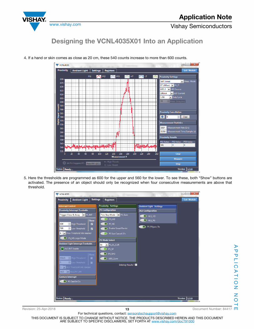
4. If a hand or skin comes as close as 20 cm, these 540 counts increase to more than 600 counts.
5. Here the thresholds are programmed as 600 for the upper and 560 for the lower. To see these, both “Show” buttons are activated. The presence of an object should only be recognized when four consecutive measurements are above that threshold.
Designing the VCNL4035X01 Into an Application
Application Notewww.vishay.com Vishay Semiconductors
AP
PL
ICA
TIO
N N
OT
E
Revision: 25-Apr-2018 14 Document Number: 84417For technical questions, contact: [email protected]
THIS DOCUMENT IS SUBJECT TO CHANGE WITHOUT NOTICE. THE PRODUCTS DESCRIBED HEREIN AND THIS DOCUMENTARE SUBJECT TO SPECIFIC DISCLAIMERS, SET FORTH AT www.vishay.com/doc?91000
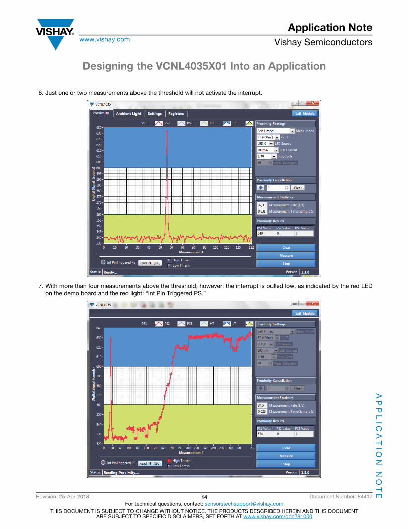
6. Just one or two measurements above the threshold will not activate the interrupt.
7. With more than four measurements above the threshold, however, the interrupt is pulled low, as indicated by the red LED on the demo board and the red light: “Int Pin Triggered PS.”

Designing the VCNL4035X01 Into an Application
Application Notewww.vishay.com Vishay Semiconductors
AP
PL
ICA
TIO
N N
OT
E
Revision: 25-Apr-2018 15 Document Number: 84417For technical questions, contact: [email protected]
THIS DOCUMENT IS SUBJECT TO CHANGE WITHOUT NOTICE. THE PRODUCTS DESCRIBED HEREIN AND THIS DOCUMENTARE SUBJECT TO SPECIFIC DISCLAIMERS, SET FORTH AT www.vishay.com/doc?91000
8. The cancellation feature is used below. The “before seen” offset counts are subtracted internally. To do so, the value of 540 is entered for register number 05 = Prox_Cancellation.
9. The “before seen” measured proximity result data of 541 is now 541 - 540 = 1. Also, the thresholds are now 540 counts lower. The higher threshold is 10 and lower is just 5.
A cover close above the sensor and the IREDslead to an offset of 540 counts….
..this is now written into register #05..
…and are set to zero
Designing the VCNL4035X01 Into an Application
Application Notewww.vishay.com Vishay Semiconductors
AP
PL
ICA
TIO
N N
OT
E
Revision: 25-Apr-2018 16 Document Number: 84417For technical questions, contact: [email protected]
THIS DOCUMENT IS SUBJECT TO CHANGE WITHOUT NOTICE. THE PRODUCTS DESCRIBED HEREIN AND THIS DOCUMENTARE SUBJECT TO SPECIFIC DISCLAIMERS, SET FORTH AT www.vishay.com/doc?91000
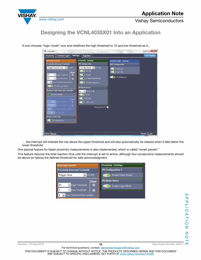
If one chooses “logic mode” now and redefines the high threshold to 10 and low threshold as 5...
… the interrupt will indicate the rise above the upper threshold and will also automatically be cleared when it falls below the lower threshold.
One special feature for faster proximity measurements is also implemented, which is called “smart persist.”
This feature reduces the total reaction time until the interrupt is set to active, although four consecutive measurements should be above (or below) the defined threshold for safe acknowledgment.
Designing the VCNL4035X01 Into an Application
Application Notewww.vishay.com Vishay Semiconductors
AP
PL
ICA
TIO
N N
OT
E
Revision: 25-Apr-2018 17 Document Number: 84417For technical questions, contact: [email protected]
THIS DOCUMENT IS SUBJECT TO CHANGE WITHOUT NOTICE. THE PRODUCTS DESCRIBED HEREIN AND THIS DOCUMENTARE SUBJECT TO SPECIFIC DISCLAIMERS, SET FORTH AT www.vishay.com/doc?91000
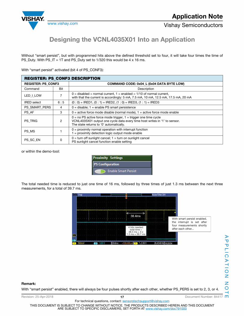
Without “smart persist”, but with programmed hits above the defined threshold set to four, it will take four times the time of PS_Duty. With PS_IT = 1T and PS_Duty set to 1/320 this would be 4 x 16 ms.
With “smart persist” activated (bit 4 of PS_CONF3):
or within the demo-tool:
The total needed time is reduced to just one time of 16 ms, followed by three times of just 1.3 ms between the next three measurements, for a total of 39.7 ms.
Remark:
With “smart persist” enabled, there will always be four pulses shortly after each other, whether PS_PERS is set to 2, 3, or 4.
REGISTER: PS_CONF3 DESCRIPTIONREGISTER: PS_CONF3 COMMAND CODE: 0x04_L (0x04 DATA BYTE LOW)
Command Bit Description
LED_I_LOW 7 0 = disabled = normal current, 1 = enabled = 1/10 of normal current, with that the current is accordingly: 5 mA, 7.5 mA, 10 mA, 12.5 mA, 17.5 mA, 20 mA
IRED select 6 : 5 (0 : 0) = IRED1, (0 : 1) = IRED2, (1 : 0) = IRED3, (1 : 1) = IRED3
PS_SMART_PERS 4 0 = disable; 1 = enable PS smart persistence
PS_AF 3 0 = active force mode disable (normal mode), 1 = active force mode enable
PS_TRIG 2 0 = no PS active force mode trigger, 1 = trigger one time cycle VCNL4035X01 output one cycle data every time host writes in ‘1’ to sensor. The state returns to ‘0’ automatically.
PS_MS 1 0 = proximity normal operation with interrupt function 1 = proximity detection logic output mode enable
PS_SC_EN 0 0 = turn off sunlight cancel; 1 = turn on sunlight cancel PS sunlight cancel function enable setting
With smart persist enabled, the interrupt is set after four measurements shortly after each other...4 hits needed:
total time =38.4 ms + 3 x
1.3 ms = 39.7 ms
Designing the VCNL4035X01 Into an Application
Application Notewww.vishay.com Vishay Semiconductors
AP
PL
ICA
TIO
N N
OT
E
Revision: 25-Apr-2018 18 Document Number: 84417For technical questions, contact: [email protected]
THIS DOCUMENT IS SUBJECT TO CHANGE WITHOUT NOTICE. THE PRODUCTS DESCRIBED HEREIN AND THIS DOCUMENTARE SUBJECT TO SPECIFIC DISCLAIMERS, SET FORTH AT www.vishay.com/doc?91000
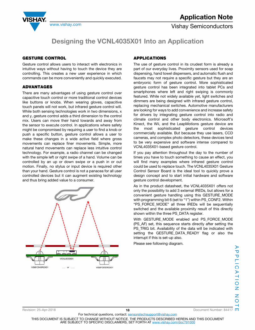
GESTURE CONTROLGesture control allows users to interact with electronics in intuitive ways without having to touch the device they are controlling. This creates a new user experience in which commands can be more conveniently and quickly executed.
ADVANTAGESThere are many advantages of using gesture control over capacitive touch control or more traditional control devices like buttons or knobs. When wearing gloves, capacitive touch panels will not work, but infrared gesture control will. While both sensing technologies work in two dimensions, x and y, gesture control adds a third dimension to the control mix. Users can move their hand towards and away from the sensor to execute control. In applications where safety might be compromised by requiring a user to find a knob or push a specific button, gesture control allows a user to make these changes in a wide active field where gross movements can replace finer movements. Simple, more natural hand movements can replace less intuitive control technology. For example, a radio channel can be changed with the simple left or right swipe of a hand. Volume can be controlled by an up or down swipe or a push in or out motion. Finally, no stylus or input device is required other than your hand. Gesture control is not a panacea for all user controlled devices but it can augment existing technology and thus bring added value to a consumer.
APPLICATIONSThe use of gesture control in its crudest form is already a part of our everyday lives. Proximity sensors used for soap dispensing, hand towel dispensers, and automatic flush and faucets may not require a specific gesture but they are an embryonic form of gesture control. More sophisticated gesture control has been integrated into tablet PCs and smartphones where left and right swiping is commonly featured. While not widely available yet, light switches and dimmers are being designed with infrared gesture control, replacing mechanical switches. Automotive manufacturers are looking for ways to add convenience and increase safety for drivers by integrating gesture control into radio and climate control and other body electronics. Microsoft’s Kinect, the Wii, and the LeapMotions gesture device are the most sophisticated gesture control devices commercially available. But because they use lasers, CCD cameras, and complex photo detectors, these devices tend to be very expensive and software intense compared to VCNL4035X01-based gesture control.
If you pay attention throughout the day to the number of times you have to touch something to cause an effect, you will find many examples where infrared gesture control could be used to replace touch. The VCNL4035X01 Gesture Control Sensor Board is the ideal tool to quickly prove a design concept and to start initial hardware and software gesture control development.
As in the product datasheet, the VCNL4035X01 offers not only the possibility to add 3 external IREDs, but allows for a convenient gesture handling using this GESTURE_MODE with programming bit 6 (set to “1”) within PS_CONF2. Within “PS_FORCE_MODE” all three IREDs will be sequentially switched and the available proximity result of this directly shown within the three PS_DATA register.
With GESTURE_MODE enabled and PS_FORCE_MODE (PS_AF) set, this sequence starts directly after setting the PS_TRIG bit. Availability of the data will be indicated with setting the GESTURE_DATA_READY flag or also the interrupt if this is set-up also.
Please see following diagram.

Designing the VCNL4035X01 Into an Application
Application Notewww.vishay.com Vishay Semiconductors
AP
PL
ICA
TIO
N N
OT
E
Revision: 25-Apr-2018 19 Document Number: 84417For technical questions, contact: [email protected]
THIS DOCUMENT IS SUBJECT TO CHANGE WITHOUT NOTICE. THE PRODUCTS DESCRIBED HEREIN AND THIS DOCUMENTARE SUBJECT TO SPECIFIC DISCLAIMERS, SET FORTH AT www.vishay.com/doc?91000
A block read format is available to speed up gesture function.
When the block read command code is received, the DATA1 is always read from the low byte of command code 08H, then high byte of command code 08H as DATA2, low byte of command code 09H (DATA3), high byte of command code 09H (DATA4), low byte of command code 0AH (DATA5) and high byte of command code 0AH (DATA6), sequentially.
The data number is assigned arbitrarily from 1 to 6, but DATA1 is always the low byte of command code 08H and the read command code sequence is 08H, 09H, and 0AH.
For example, in gesture function, if the command code is read 0xC1 xx xx xx xx xx xx, then the master will receive 6 bytes. Data byte 1 is LED1 data byte low, data byte 2 is LED1 data byte high, data byte 3 is LED2 data byte low, and data byte 4 is LED2 data byte high and then data byte 5 is LED3 data byte low, and data byte 6 is LED3 data byte high.
Please see below diagram.
The three proximity measurements for this automatic gesture function are done within a short fixed time frame, but also depend on the programmed integration time.
For PS_IT = 2T = 100 μs the total time frame is 600 μs for proximity and DC light measurement, for PS_IT = 8T = 400 μs the total time frame is then 2400 μs for proximity and DC light measurement.
Fig. 26 - Gesture Timing for PS_IT = 2T = 100 μs Fig. 27 - Gesture Timing for PS_IT = 8T = 400 μs
IRED1 IRED2 IRED3
PS_MS
INT_GESTURE_EN
PS_FORCE_MODE
PS_TRIG
PS_OPERATION_SEQUENCE
GESTURE_DATA_READY FLAG
INTERRUPT
GESTURE DATA
S A PAAAA AAR / WSLAVE ADDRESS DATA1 DATA5DATA4DATA3DATA2 DATA6
(read) Data transferred (n bytes and acknowledge)
600 μs 2400 μs
Designing the VCNL4035X01 Into an Application
Application Notewww.vishay.com Vishay Semiconductors
AP
PL
ICA
TIO
N N
OT
E
Revision: 25-Apr-2018 20 Document Number: 84417For technical questions, contact: [email protected]
THIS DOCUMENT IS SUBJECT TO CHANGE WITHOUT NOTICE. THE PRODUCTS DESCRIBED HEREIN AND THIS DOCUMENTARE SUBJECT TO SPECIFIC DISCLAIMERS, SET FORTH AT www.vishay.com/doc?91000
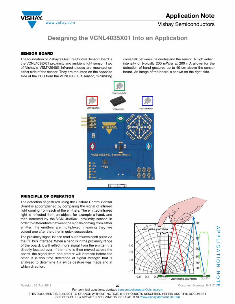
SENSOR BOARDThe foundation of Vishay’s Gesture Control Sensor Board is the VCNL4035X01 proximity and ambient light sensor. Two of Vishay’s VSMY2940G infrared diodes are mounted on either side of the sensor. They are mounted on the opposite side of the PCB from the VCNL4035X01 sensor, minimizing
cross talk between the diodes and the sensor. A high radiant intensity of typically 200 mW/sr at 200 mA allows for the detection of hand gestures up to 40 cm above the sensor board. An image of the board is shown on the right side.
PRINCIPLE OF OPERATIONThe detection of gestures using the Gesture Control Sensor Board is accomplished by comparing the signal of infrared light coming from each of the emitters. The emitted infrared light is reflected from an object, for example a hand, and then detected by the VCNL4035X01 proximity sensor. In order to differentiate between the signals coming from either emitter, the emitters are multiplexed, meaning they are pulsed one after the other in quick succession.
The proximity signal is then read out between each pulse via the I2C bus interface. When a hand is in the proximity range of the board, it will reflect more signal from the emitter it is directly located over. If the hand is then moved across the board, the signal from one emitter will increase before the other. It is this time difference of signal strength that is analyzed to determine if a swipe gesture was made and in which direction.

Designing the VCNL4035X01 Into an Application
Application Notewww.vishay.com Vishay Semiconductors
AP
PL
ICA
TIO
N N
OT
E
Revision: 25-Apr-2018 21 Document Number: 84417For technical questions, contact: [email protected]
THIS DOCUMENT IS SUBJECT TO CHANGE WITHOUT NOTICE. THE PRODUCTS DESCRIBED HEREIN AND THIS DOCUMENTARE SUBJECT TO SPECIFIC DISCLAIMERS, SET FORTH AT www.vishay.com/doc?91000
GESTURE RECOGNITIONThe detection of a gesture is composed of two main parts: The acquisition and preparation of the raw data to be analyzed and the interpretation of this raw data by the detection algorithm. If a gesture is recognized, a corresponding event is triggered.
Data Acquisition
The data used for gesture recognition is acquired in separate data streams, one per emitter. As the emitters are multiplexed (and only one emitter should be on at a time), the measurements occur slightly one after the other. One measurement cycle consists of a set of data from each channel. The measurements are done in quick succession so that the time required to complete a full measurement cycle is much greater than the time between the individual proximity measurements of each IRED. In this way the signals can be compared with one another in close to real time.
If the jumps between measurements are seen to be too erratic, for example if the sensor is in a high noise environment, several measurements per emitter and per measurement cycle can be made and averaged. This will slow down the measurement speed, but it will result in a cleaner signal. This variable can be adjusted in the provided gesture demo software, as will be discussed later.
To be able to analyze and compare the data streams of each emitter channel with one another, the data of each stream is split into frames of “n” measurements. Here, each frame
contains the latest “n” measurements, with each iteration of the measurement cycle, moving the frame over by one. The recognition algorithm analyzes each frame and once a frame is seen to contain a gesture, the next few frames are ignored, in order to avoid detecting the same gesture twice. Furthermore, by ignoring several frames after a valid gesture has been detected, it is possible to reduce false positives from hand movements in the sensor’s field of view that were not intended as a gesture. This variable can be adjusted in the provided gesture demo software.

Designing the VCNL4035X01 Into an Application
Application Notewww.vishay.com Vishay Semiconductors
AP
PL
ICA
TIO
N N
OT
E
Revision: 25-Apr-2018 22 Document Number: 84417For technical questions, contact: [email protected]
THIS DOCUMENT IS SUBJECT TO CHANGE WITHOUT NOTICE. THE PRODUCTS DESCRIBED HEREIN AND THIS DOCUMENTARE SUBJECT TO SPECIFIC DISCLAIMERS, SET FORTH AT www.vishay.com/doc?91000
Detection Algorithm
Each frame of the acquired signal is analyzed for two parameters: the standard deviation of each signal and the time delay between signals. By comparing the results of this analysis to user-defined thresholds, the algorithm can tell whether and what kind of a gesture was made.
The standard deviation is a measure of the spread of the data within the frame being analyzed. It is calculated using the following formula:
Where x is the mean of the current frame and n is the amount of samples being analyzed, i.e. frame length.
A low standard deviation implies there is no change in the signal and there is either no hand in the sensor’s detection area or the hand is being held steady over the sensor and no swipe or push gesture is being made. A high standard deviation implies a large change in the signal, suggesting the movement of the hand across or towards the sensor. The detection algorithm only analyzes the frame for further parameters, if the signal is above a set standard deviation threshold.
The presence of a sufficient time delay between the signals signifies that a swipe gesture has been made. In the detection algorithm implemented in the SensorXplorerTM, the time delay is found by measuring the cross correlation between the two signals. The cross correlation can be calculated by the following formula:
where f[x] and g[x] are individual data streams from either IRED and f*denoted the conjugate of f.
The cross correlation effectively shifts one of the signals over the other and computes the percent overlay of their integrals. By taking note of the point at which there is a maximum cross correlation between the two signals, an estimation of the time delay between the two signals can be found. As the cross correlation of the signals is always computed in the same order, regardless of which of the signals comes first, the time delay will either be positive or negative. The sign of the time delay denotes the direction of the swipe gesture. The decision on whether a right or left swipe was detected is only made when this time delay threshold is exceeded.
Both the time delay threshold and the standard deviation threshold can be adjusted in the demo software, allowing you to test and fine tune for your application.
The method described above is very sensitive and robust, but there are other, less computationally intensive ways to detect gestures. For example, one can monitor a threshold over which hand entry and hand exit events are detected. An initial rising edge of the threshold of a channel denotes the presence of a hand over that emitter, and a falling edge means the hand has left the detection area. Depending on the event order, a differentiation can be made between a left
sx - x( )
2
n - 1---------------------------=
corr f[x], g[x]( ) f* k[ ]g x + k( )k = -∞
∞
=
Designing the VCNL4035X01 Into an Application
Application Notewww.vishay.com Vishay Semiconductors
AP
PL
ICA
TIO
N N
OT
E
Revision: 25-Apr-2018 23 Document Number: 84417For technical questions, contact: [email protected]
THIS DOCUMENT IS SUBJECT TO CHANGE WITHOUT NOTICE. THE PRODUCTS DESCRIBED HEREIN AND THIS DOCUMENTARE SUBJECT TO SPECIFIC DISCLAIMERS, SET FORTH AT www.vishay.com/doc?91000
and a right swipe. This method has no need for framing, and instead analyzes the result of each measurement cycle one by one. This approach may be more suitable for some
applications. Such an algorithm was also tested with the Gesture Sensor Board, and the VCNL4035X01 proved to be just as effective.
GESTURE CONTROL DEMO SOFTWARE
Gesture Function Tab
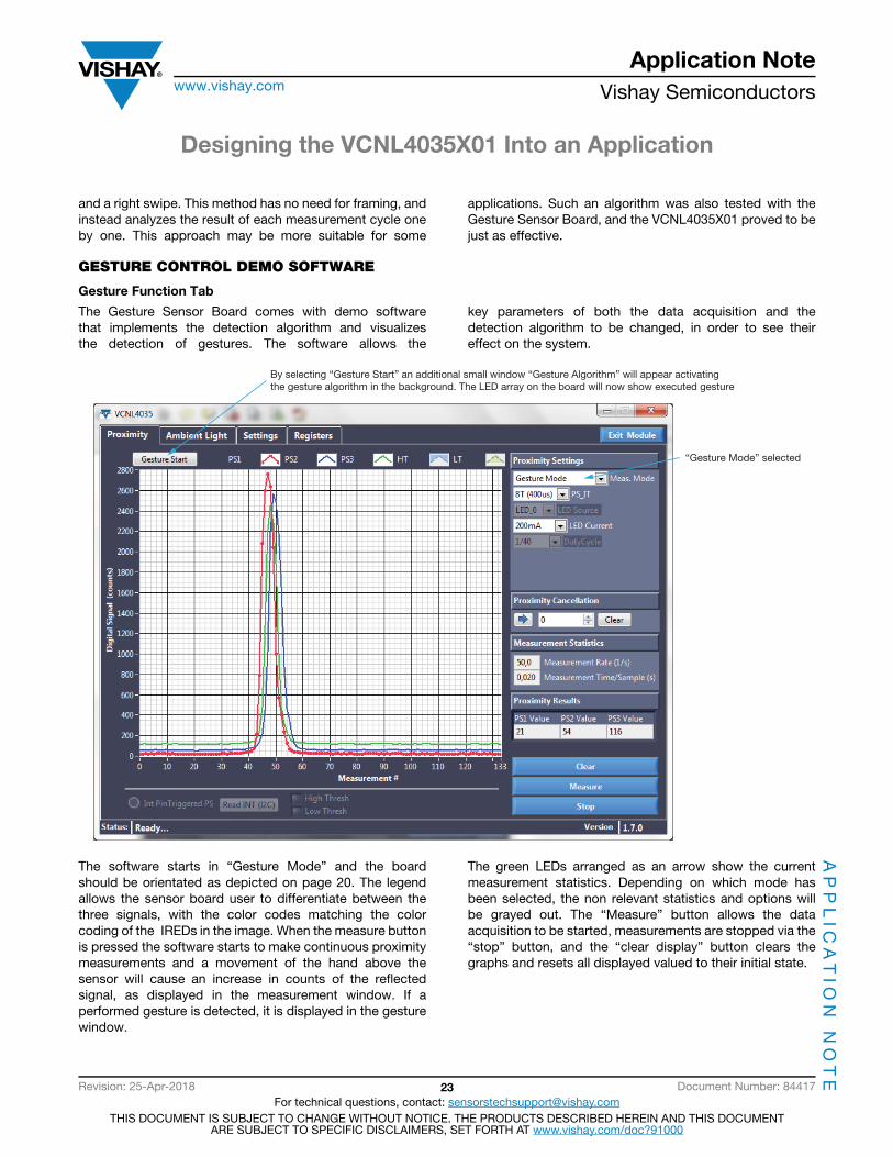
The Gesture Sensor Board comes with demo software that implements the detection algorithm and visualizes the detection of gestures. The software allows the
key parameters of both the data acquisition and the detection algorithm to be changed, in order to see their effect on the system.
The software starts in “Gesture Mode” and the board should be orientated as depicted on page 20. The legend allows the sensor board user to differentiate between the three signals, with the color codes matching the color coding of the IREDs in the image. When the measure button is pressed the software starts to make continuous proximity measurements and a movement of the hand above the sensor will cause an increase in counts of the reflected signal, as displayed in the measurement window. If a performed gesture is detected, it is displayed in the gesture window.
The green LEDs arranged as an arrow show the current measurement statistics. Depending on which mode has been selected, the non relevant statistics and options will be grayed out. The “Measure” button allows the data acquisition to be started, measurements are stopped via the “stop” button, and the “clear display” button clears the graphs and resets all displayed valued to their initial state.
“Gesture Mode” selected
By selecting “Gesture Start” an additional small window “Gesture Algorithm” will appear activatingthe gesture algorithm in the background. The LED array on the board will now show executed gesture

Designing the VCNL4035X01 Into an Application
Application Notewww.vishay.com Vishay Semiconductors
AP
PL
ICA
TIO
N N
OT
E
Revision: 25-Apr-2018 24 Document Number: 84417For technical questions, contact: [email protected]
THIS DOCUMENT IS SUBJECT TO CHANGE WITHOUT NOTICE. THE PRODUCTS DESCRIBED HEREIN AND THIS DOCUMENTARE SUBJECT TO SPECIFIC DISCLAIMERS, SET FORTH AT www.vishay.com/doc?91000
Parameters for Gesture Detection:
• Slope Threshold: this defines the threshold of the slope of the signal, that needs to be crossed, in order for a push gesture to be detected. The slopes of the last five frames of every signal are added together and compared to the slope threshold. If all three surpass this threshold, a push gesture is executed. Thus, the higher this threshold is set, the higher the successive slope increase needs to be for a push gesture to be detected. In order of importance, the algorithm first checks if the up / down or left / right thresholds, as described below, did not execute a gesture, before checking the slope threshold.
• Standard Deviation Threshold: the standard deviation is a measure of the spread of the data within each frame. The movement of the hand over the gesture board will increase the standard deviation of both signals. The detection algorithm will only scan the frames for a time delay between the signals if the standard deviation surpasses this set threshold. This threshold should be set higher than any seen signal noise. The further away from the sensor a gesture is performed, the smaller the change in standard deviation, as fewer counts are detected. The gesture detection range increases with a lower standard deviation threshold, as less change in the signal is required to exceed the threshold.
• Up / Down Threshold and Left / Right Threshold: these thresholds determine the minimum required time delay, for up / down and left / right swipes respectively, that needs to be detected by the gesture algorithm, for the algorithm to execute a gesture event and analyze if it was a negative (left swipe or down swipe) or positive (right swipe or up swipe) delay. The detectable time difference will depend on the measurement rate. With a lower measurement rate (higher delay time) the measurement time resolution decreases and so the time delay threshold must be decreased. The width of the object used to perform the gesture should also be taken into consideration. A thinner object will lead to a higher detected time delay between signals, whereas a wider object will lead to a lower detected time delay.
• Upper Threshold / Lower Threshold: this defines the thresholds that needs to be crossed (above for high and below for low threshold) to for presence detection. On the gesture board, this is displayed by the red LED’s in the LED arrangement in the corner of the board. Such a threshold could be used to “wake up” the gesture sensor, and directly programmed into the threshold registers on the chip. In the demonstration software this is done on the software side, in order to keep the sensor in gesture mode constantly.
An example of a successfully detected right swipe can be seen below:
The gesture sensor board is an add-on board to the SensorXplorer. More information about this demo kit can be found at www.vishay.com/optoelectronics/SensorXplorer.
Please purchase a VCNL4035X01 gesture sensor board at any listed distributors: www.vishay.com/optoelectronics/SensorXplorer.
“Right” arrow lighted up

Designing the VCNL4035X01 Into an Application
Application Notewww.vishay.com Vishay Semiconductors
AP
PL
ICA
TIO
N N
OT
E
Revision: 25-Apr-2018 25 Document Number: 84417For technical questions, contact: [email protected]
THIS DOCUMENT IS SUBJECT TO CHANGE WITHOUT NOTICE. THE PRODUCTS DESCRIBED HEREIN AND THIS DOCUMENTARE SUBJECT TO SPECIFIC DISCLAIMERS, SET FORTH AT www.vishay.com/doc?91000
SCHEMATIC

Designing the VCNL4035X01 Into an Application
Application Notewww.vishay.com Vishay Semiconductors
AP
PL
ICA
TIO
N N
OT
E
Revision: 25-Apr-2018 26 Document Number: 84417For technical questions, contact: [email protected]
THIS DOCUMENT IS SUBJECT TO CHANGE WITHOUT NOTICE. THE PRODUCTS DESCRIBED HEREIN AND THIS DOCUMENTARE SUBJECT TO SPECIFIC DISCLAIMERS, SET FORTH AT www.vishay.com/doc?91000