Designing the Controller for an Electromechanical System ...€¦ · 3 What are the challenges?...
34
1 © 2015 The MathWorks, Inc. Designing the Controller for an Electromechanical System Using a Power Window Example Vivek Raju Application Engineer – Control Design MathWorks DC Motor
Transcript of Designing the Controller for an Electromechanical System ...€¦ · 3 What are the challenges?...
1© 2015 The MathWorks, Inc.
Designing the Controller for an
Electromechanical System Using a
Power Window Example
Vivek Raju
Application Engineer – Control Design
MathWorksDC Motor
2
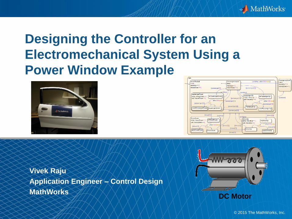
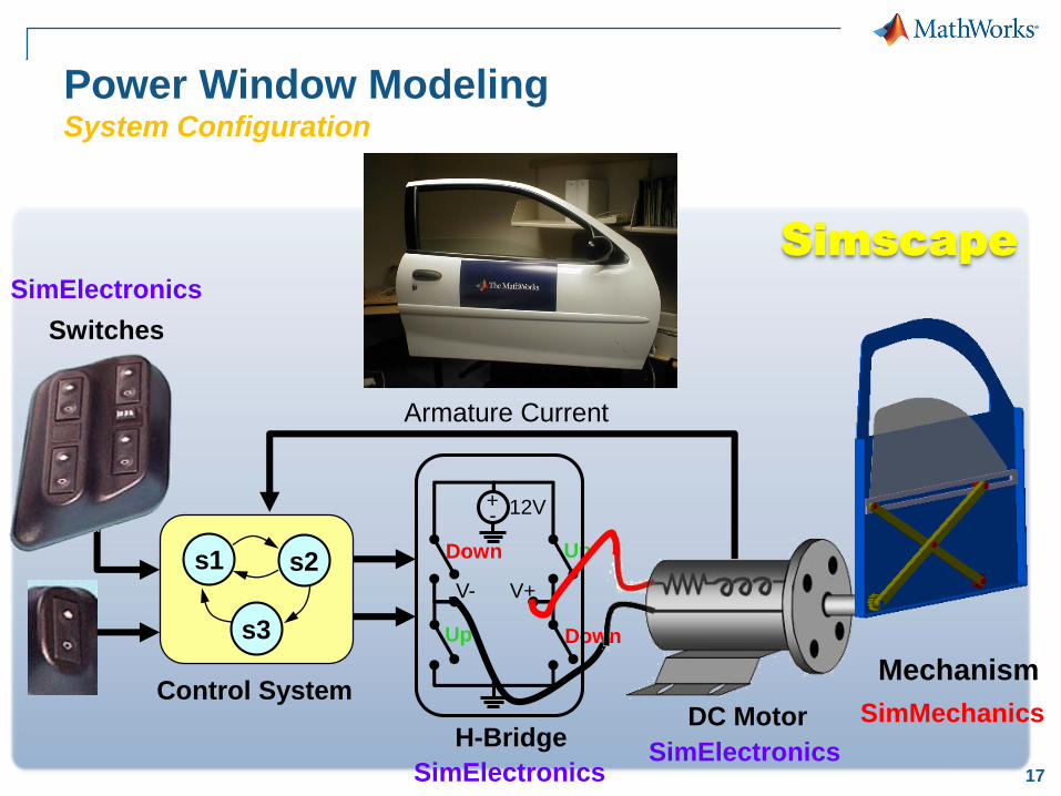
Power Window ModelingSystem Configuration
Armature Current
+- 12V
Up
Up Down
Down
V+V-
H-BridgeDC Motor
s1 s2
s3
Control SystemMechanism
Switches
3
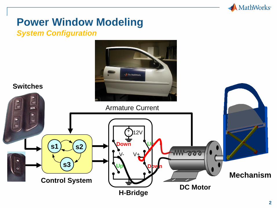
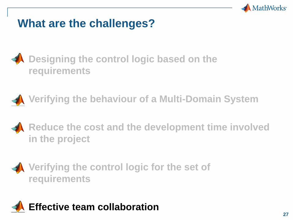
What are the challenges?
Designing the control logic based on the
requirements
Verifying the behaviour of a Multi-Domain System
Reduce the cost and the development time involved
in the project
Verifying the control logic for the set of
requirements
Effective team collaboration
4
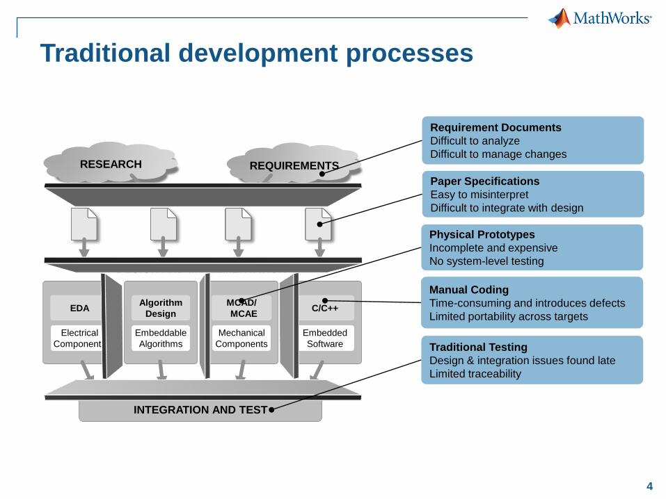
Traditional development processes
Embedded
Software
C/C++
Electrical
Components
EDA
RESEARCH REQUIREMENTS
SPECIFICATIONS
DESIGN AND IMPLEMENTATION
Mechanical
Components
MCAD/
MCAE
Embeddable
Algorithms
Algorithm
Design
DESIGN AND IMPLEMENTATION
INTEGRATION AND TEST
Requirement Documents
Difficult to analyze
Difficult to manage changes
Paper Specifications
Easy to misinterpret
Difficult to integrate with design
Physical Prototypes
Incomplete and expensive
No system-level testing
Manual Coding
Time-consuming and introduces defects
Limited portability across targets
Traditional Testing
Design & integration issues found late
Limited traceability
5
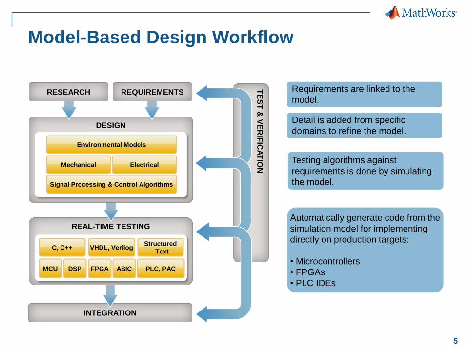
Model-Based Design Workflow
Testing algorithms against
requirements is done by simulating
the model.
Requirements are linked to the
model.
Detail is added from specific
domains to refine the model.
Automatically generate code from the
simulation model for implementing
directly on production targets:
• Microcontrollers
• FPGAs
• PLC IDEs
INTEGRATION
REAL-TIME TESTING
Structured
TextVHDL, VerilogC, C++
MCU DSP FPGA ASIC PLC, PAC
DESIGN
Environmental Models
Signal Processing & Control Algorithms
Mechanical Electrical
RESEARCH REQUIREMENTS
TE
ST
& V
ER
IFIC
AT
ION
6
All the challenges can be
addressed by Model-Based
Design
Let us explore!!!
7
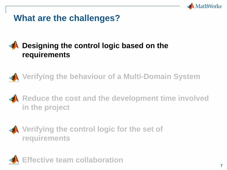
What are the challenges?
Designing the control logic based on the
requirements
Verifying the behaviour of a Multi-Domain System
Reduce the cost and the development time involved
in the project
Verifying the control logic for the set of
requirements
Effective team collaboration
8
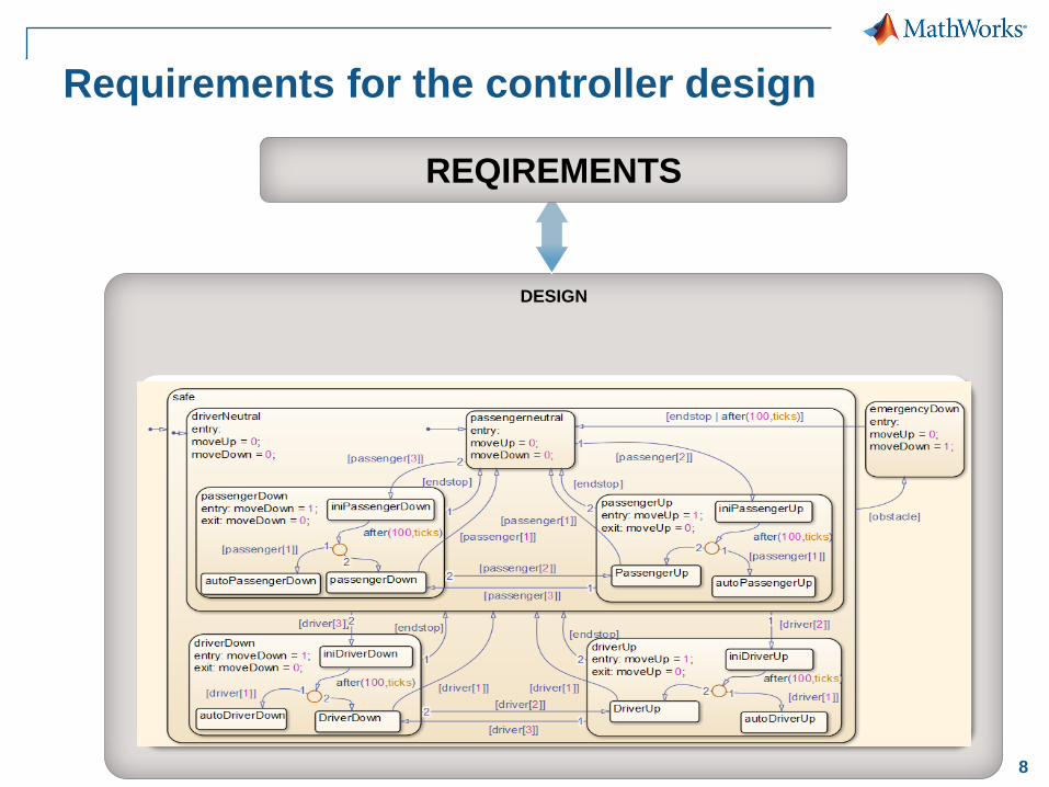
Requirements for the controller design
DESIGN
REQIREMENTS
Control
Algorithms
9
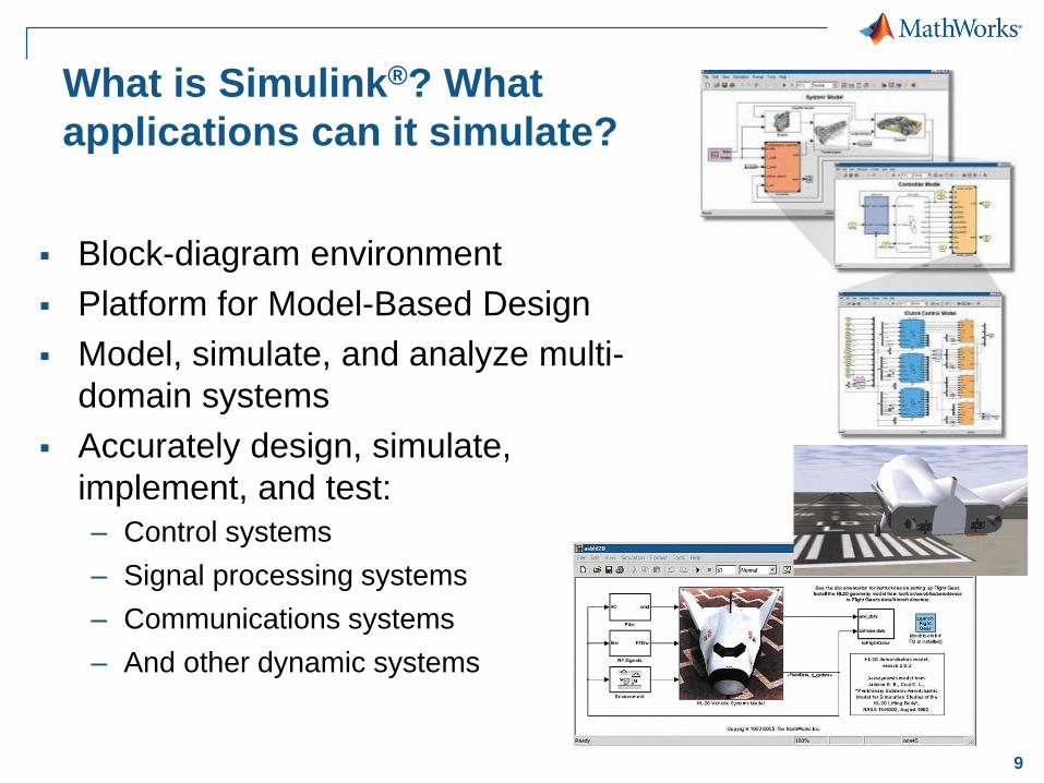
What is Simulink®? What
applications can it simulate?
Block-diagram environment
Platform for Model-Based Design
Model, simulate, and analyze multi-
domain systems
Accurately design, simulate,
implement, and test:
– Control systems
– Signal processing systems
– Communications systems
– And other dynamic systems
10
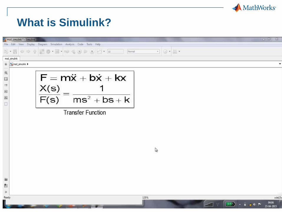
What is Simulink?
11
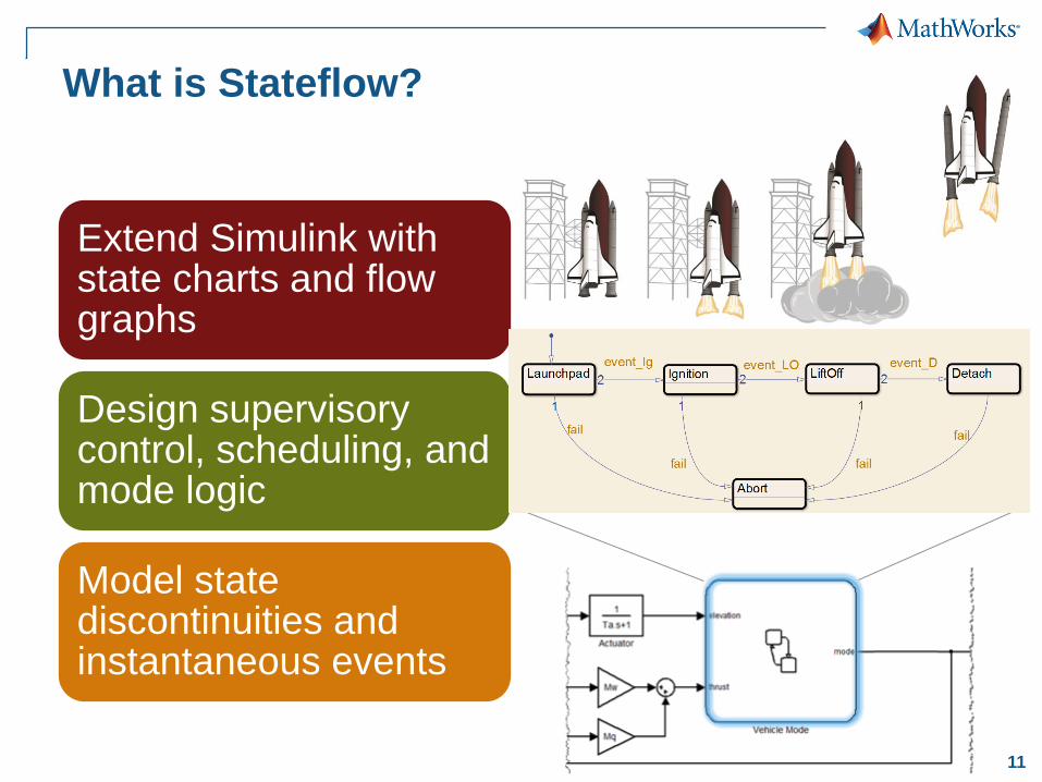
What is Stateflow?
Extend Simulink with state charts and flow graphs
Design supervisory control, scheduling, and mode logic
Model state discontinuities and instantaneous events
12
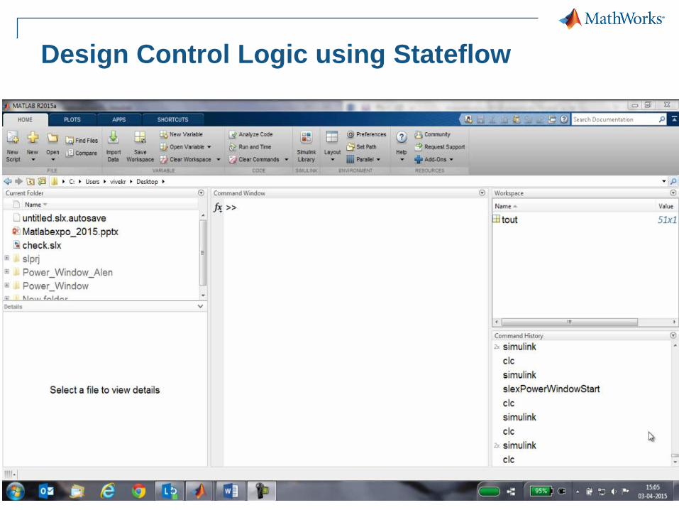
Design Control Logic using Stateflow
13
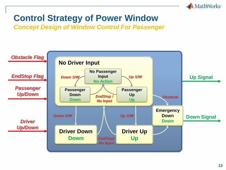
Up Signal
Down SignalDriver
Up/Down
Obstacle Flag
Passenger
Up/Down
EndStop Flag
No Driver Input
Driver Down
Down
Driver Up
Up
No Passenger
Input
No Action
Passenger
Down
Down
Passenger
Up
Up
Control Strategy of Power WindowConcept Design of Window Control For Passenger
Down S/W Up S/W
EndStop /
No Input
Up S/WDown S/W
EndStop/
No Input
Emergency
Down
Down
Obstacle
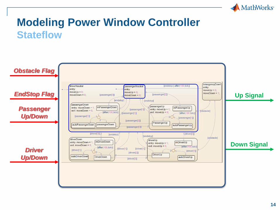
14
Modeling Power Window ControllerStateflow
Up Signal
Down SignalDriver
Up/Down
Obstacle Flag
Passenger
Up/Down
EndStop Flag
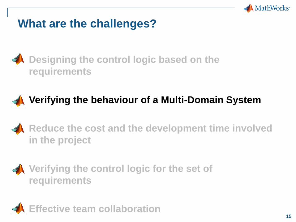
15
What are the challenges?
Designing the control logic based on the
requirements
Verifying the behaviour of a Multi-Domain System
Reduce the cost and the development time involved
in the project
Verifying the control logic for the set of
requirements
Effective team collaboration

16
Verifying the control logic against a dynamic
system
DESIGN
REQIREMENTS
Control
Algorithms
Multi-Doman
Plant Model
17
Simscape
Power Window ModelingSystem Configuration
Armature Current
+- 12V
Up
Up Down
Down
V+V-
H-BridgeDC Motor
s1 s2
s3
Control SystemSimMechanics
SimElectronicsSimElectronics
SimElectronics
Mechanism
Switches
18
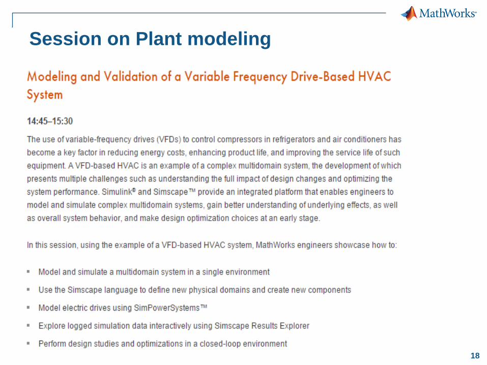
Session on Plant modeling
19
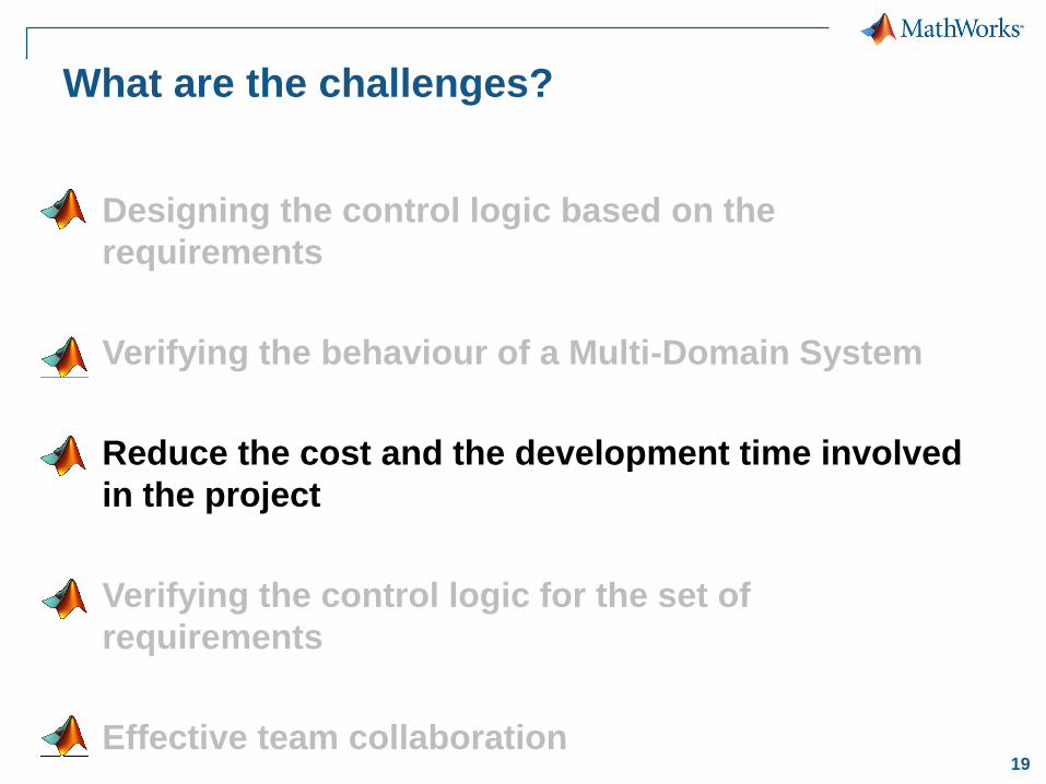
What are the challenges?
Designing the control logic based on the
requirements
Verifying the behaviour of a Multi-Domain System
Reduce the cost and the development time involved
in the project
Verifying the control logic for the set of
requirements
Effective team collaboration
20
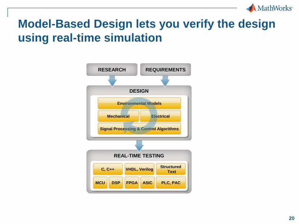
Model-Based Design lets you verify the design
using real-time simulation
REAL-TIME TESTING
Structured
TextVHDL, VerilogC, C++
MCU DSP FPGA ASIC PLC, PAC
DESIGN
Environmental Models
Signal Processing & Control Algorithms
Mechanical Electrical
RESEARCH REQUIREMENTS
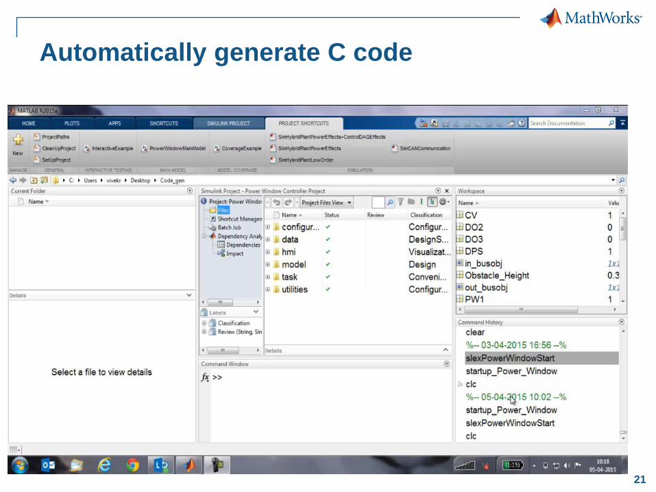
21
Automatically generate C code
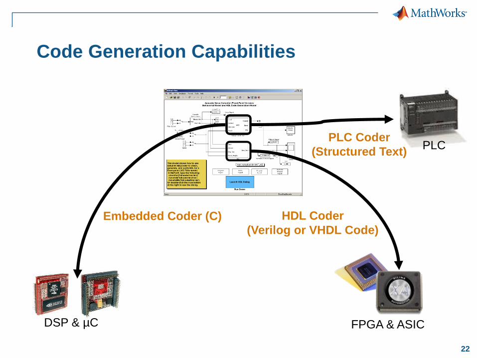
22
Code Generation Capabilities
Embedded Coder (C)
DSP & µC FPGA & ASIC
HDL Coder
(Verilog or VHDL Code)
PLCPLC Coder
(Structured Text)
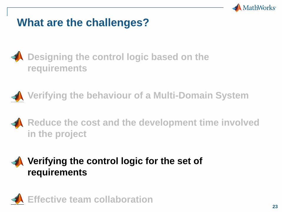
23
What are the challenges?
Designing the control logic based on the
requirements
Verifying the behaviour of a Multi-Domain System
Reduce the cost and the development time involved
in the project
Verifying the control logic for the set of
requirements
Effective team collaboration

24
Verify the model as well as the generated code
TE
ST
& V
ER
IFIC
AT
ION
REAL-TIME TESTING
Structured
TextVHDL, VerilogC, C++
MCU DSP FPGA ASIC PLC, PAC
DESIGN
Environmental Models
Signal Processing & Control Algorithms
Mechanical Electrical
RESEARCH REQUIREMENTST
ES
T &
VE
RIF
ICA
TIO
N
25
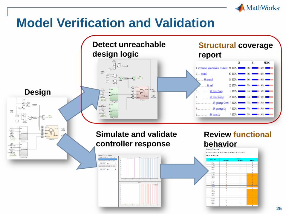
Functional testing (black-box)
Structural testing (white-box)
Design
Model Verification and Validation
Simulate and validate
controller responseReview functional
behavior
Structural coverage
report
Detect unreachable
design logic
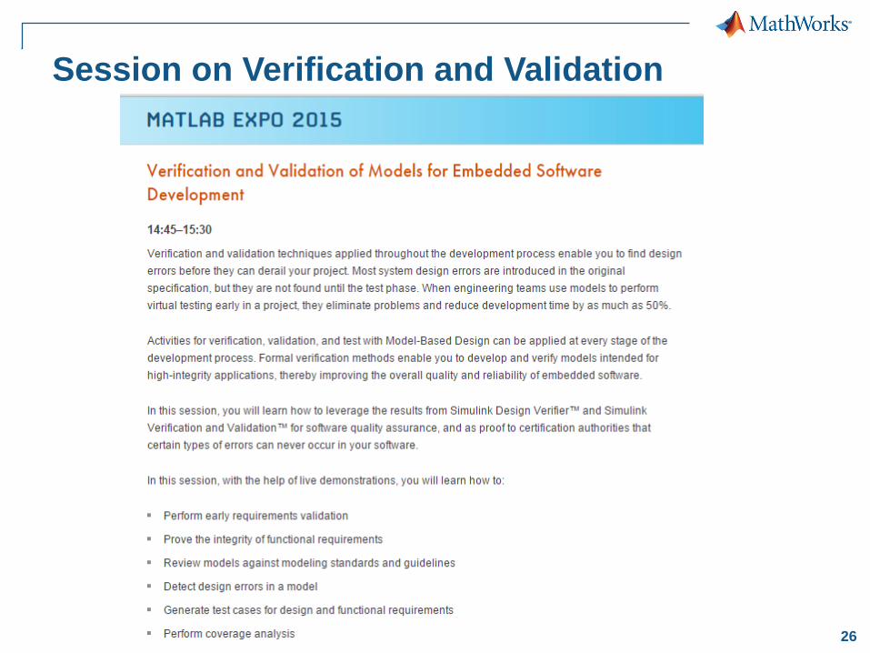
26
Session on Verification and Validation
27
What are the challenges?
Designing the control logic based on the
requirements
Verifying the behaviour of a Multi-Domain System
Reduce the cost and the development time involved
in the project
Verifying the control logic for the set of
requirements
Effective team collaboration
28
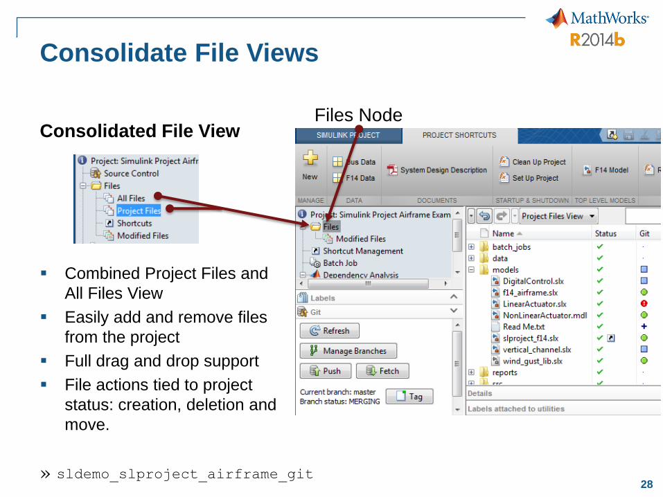
Consolidate File Views
Combined Project Files and
All Files View
Easily add and remove files
from the project
Full drag and drop support
File actions tied to project
status: creation, deletion and
move.
Consolidated File View
» sldemo_slproject_airframe_git
Files Node
29
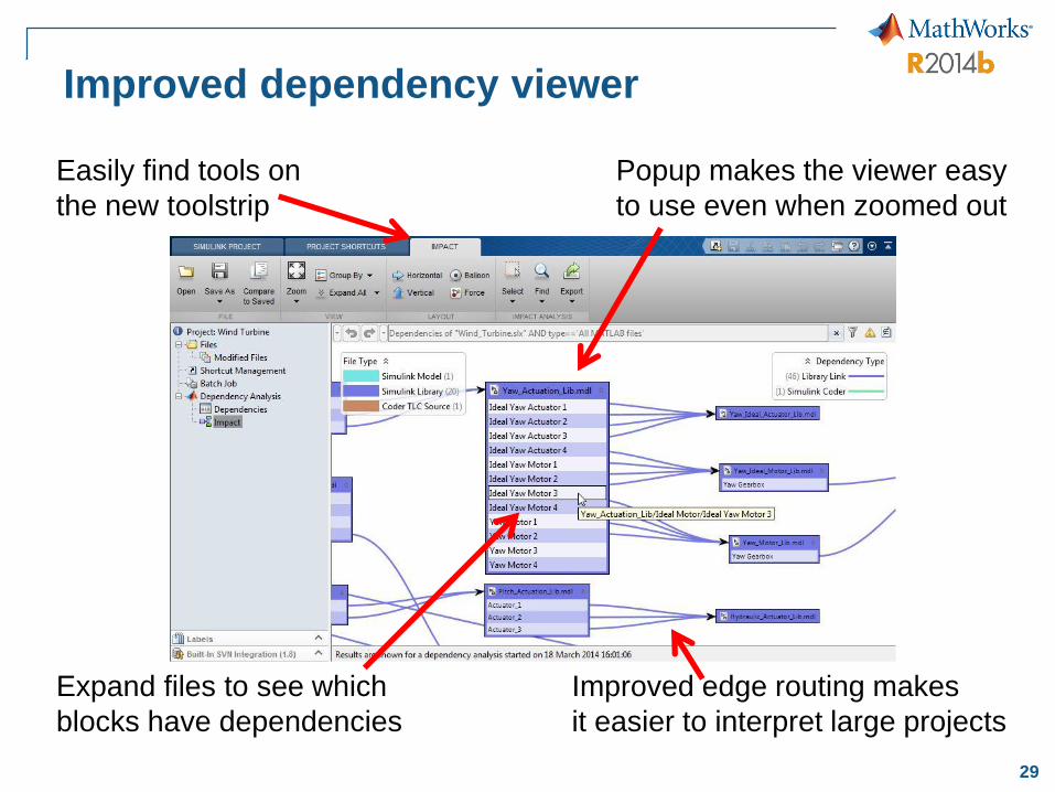
Improved dependency viewer
Easily find tools on
the new toolstrip
Expand files to see which
blocks have dependencies
Popup makes the viewer easy
to use even when zoomed out
Improved edge routing makes
it easier to interpret large projects
30
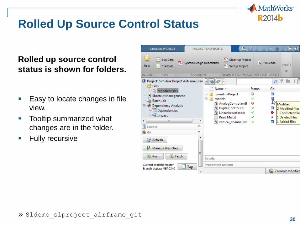
Rolled Up Source Control Status
Easy to locate changes in file
view.
Tooltip summarized what
changes are in the folder.
Fully recursive
Rolled up source control
status is shown for folders.
» Sldemo_slproject_airframe_git
Screen shot of the feature in
action
31
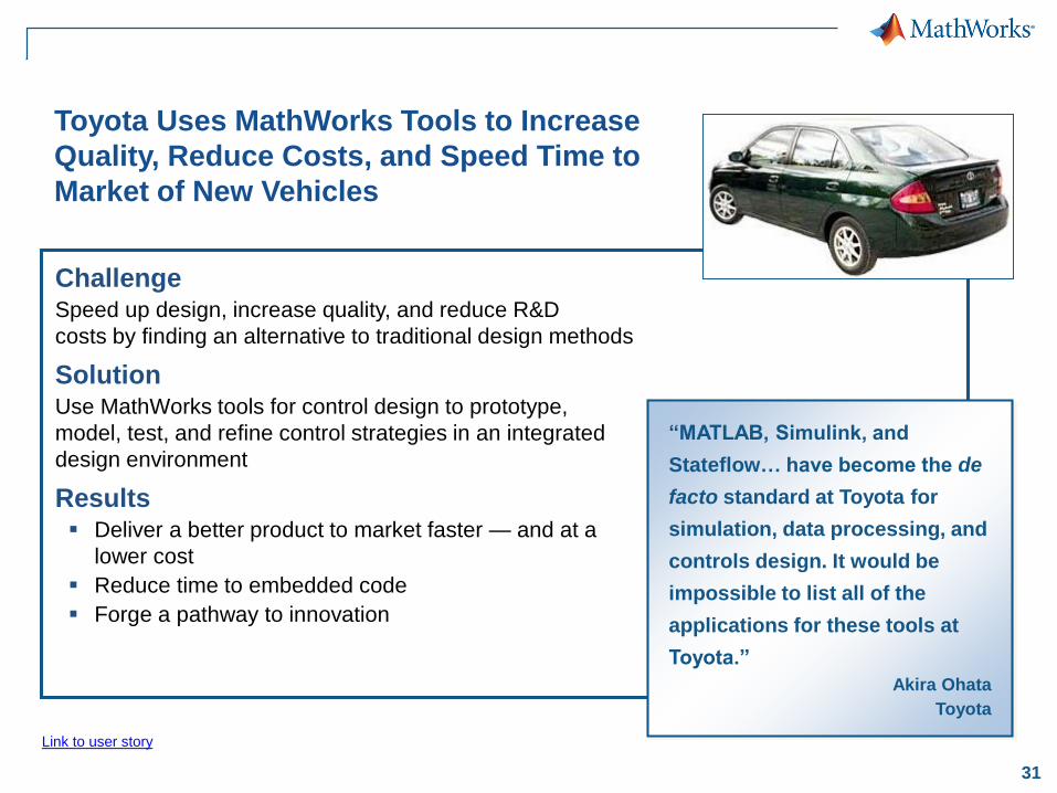
Toyota Uses MathWorks Tools to Increase
Quality, Reduce Costs, and Speed Time to
Market of New Vehicles
ChallengeSpeed up design, increase quality, and reduce R&D
costs by finding an alternative to traditional design methods
SolutionUse MathWorks tools for control design to prototype,
model, test, and refine control strategies in an integrated
design environment
Results Deliver a better product to market faster — and at a
lower cost
Reduce time to embedded code
Forge a pathway to innovation
“MATLAB, Simulink, and
Stateflow… have become the de
facto standard at Toyota for
simulation, data processing, and
controls design. It would be
impossible to list all of the
applications for these tools at
Toyota.”
Akira Ohata
Toyota
Link to user story

32
ChallengeSpeed the development and certification
of a power electronics control system for a
distributed power storage system
SolutionUse Model-Based Design with MATLAB and Simulink
to run simulations of power electronics, the electrical
grid, and controller; generate production
microcontroller code; and achieve certification
Results Six months of development time saved
Thousands of dollars in board spin costs saved
System fully operational days after hardware
becomes available
Stem Accelerates Development of
Power Electronics Control Systems with
Model-Based Design
A commercial installation of Stem’s
PowerStore energy system.
Link to user story
“With Model-Based Design we
saw exactly how our controller
would work with the hardware
even while the hardware was
being developed. After we had the
hardware, refinements were easy
because the simulations matched
what we saw on the scope, and
that gave us tremendous
confidence in the design.”
David Erhart
Stem
33
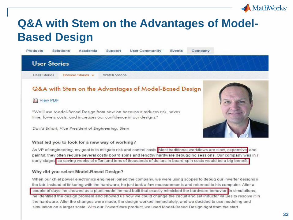
Q&A with Stem on the Advantages of Model-
Based Design

34
Thank you
Any Questions?