Improved Interfaces for Human-Robot Interaction in Urban ...
Designing Interfaces for Robot Control Based on Semiotic Engineering
Luıs Felipe Hussin Bento, Raquel Oliveira Prates, Luiz ChaimowiczDepartment of Computer Science
Universidade Federal de Minas GeraisBelo Horizonte, Brazil
[email protected], [email protected], [email protected]
Abstract—This paper explores the use of Semiotic Engineeringtheory in the design of different interfaces for the control of amobile robot. Based on a set of sign classes for human-robotinteraction, we have elaborated a common interaction modeland designed different interfaces for controlling an e-puck robot,a small sized mobile robot used for education and research.We implemented three interfaces using different technologies(desktop, Tablet PC, and handheld) and tested them with agroup of users, in order to evaluate if the sign classes and theirrepresentations were adequate and also the differences perceivedin the use of diverse interaction technologies.
Keywords-human-robot interaction, semiotic engineering, e-puck, interfaces
I. INTRODUCTION
Human-Robot Interaction (HRI) has become a very activefield, attracting researchers from various areas, such asrobotics and human-computer interaction as well as fromthe humanities (psychology, anthropology and sociologyamong others). This growing interest is motivated by theexpectation of an increasing number of robots being used insociety by people who are not specialists, creating demandson interaction quality.
In general, different types of interfaces can be designedfor human-robot interaction: software interfaces in desktopsor mobile computers [1], touch interfaces such as TabletPCs [2], tangible interfaces [3] or visual, audio and gesturalcommands [4]. Despite their differences, it is possible toanalyze these interfaces looking for common interaction modelthat will depend mostly on the characteristics of the tasks beingcommanded by the user to the robots that are executing them.
This paper presents the design and implementation ofdifferent interfaces for controlling a small sized robot. Webase our design on Semiotic Engineering, an HCI theory thatconsiders the interaction between people and computers asa particular case of the computer-mediated communicationbetween humans. Building on our previous work [5], in whichwe identified a set of sign classes for the control of ane-puck robot, we propose a common interaction model forcontrolling the e-puck and design three different interfaces:one for desktop PCs that uses keyboard and mouse; other forTablet PCs, based on the interaction using a pen directly on thescreen; and one for a mobile device (an iPod touch R©), whichallows interaction through its touch screen and the movementof the device itself. The interfaces were evaluated by a groupof users in the execution of different tasks and the obtainedresults are analyzed and discussed.
Some works in the literature have proposed the analysis ofdifferent interfaces under a common framework. Richer andDrury [6], for example, proposed a framework to describeinterfaces based on video games. They analyzed several gametypes and described the interaction in terms of the componentsof gaming interfaces and the successful interaction styles usedon these games. This framework can help a robot interfaceproject by providing descriptions for interface components thatare application-independent, creating a common language foranalysis and comparison of different works.
Fong et al [7] presented a collaborative system for robotteleoperation based on a dialog between the user and the robot.The robot can ask questions to the user about its conditionand how to proceed in certain situations. The user can alsoask questions to the robot regarding its state and task status.This dialog allows the levels of autonomy and human-robotinteraction to vary according to each situation, being speciallyuseful for environments that are unknown or pose difficultiesfor planning.
Steinfeld et al. [8] proposed common metrics to improvequality of HRI and also evaluate existing interfaces, providingsome common basis for research comparison. Due to thediverse range of human-robot applications, they state that itis not simple to propose metrics, but they believe that themetrics they have proposed will be able to cover a wide rangeof these applications.
All these works focused more on evaluating existinginterfaces and trying to provide a common ground forresearch analysis. The Video Game Based Frameworkproposed by Richer and Drury can also be used on design,but it deals mostly with interface feedback rather than withthe interaction itself. Our main contribution presented in thispaper is the use of Semiotic Engineering to identify somecommon aspects in human-robot interaction, more specificallyin the control of mobile robots, and to use these aspects inthe design of different interfaces.
This paper is organized as follows: next section presentsthe sign classes for robot interaction based on SemioticEngineering. In Section III we present how the interfaceswere designed based on these classes and in Section IV weshow how this design was applied in the development of theinterfaces. Section V describes user tests with the implementedinterfaces, with the results of these tests being presented inSection VI. Finally, in Section VII, we discuss the results andpresent our final remarks.
II. SIGN CLASSES FOR HUMAN-ROBOT INTERACTION
Our goal was to investigate the impact of the use of differenttechnologies in teleoperating a robot. Thus, the first stepwas to elaborate an abstract interaction model that coulddescribe what aspects needed to be conveyed in the user-system interaction, independently of the technologies used.The idea was that by identifying common aspects in mobilerobot control and teleoperation we would then be able toelaborate such model.
In order to do so, we based our work on SemioticEngineering [9], an explanatory, i.e. non-predictive, theory ofHCI that perceives an interactive system as a designer-to-usercommunication. The designers convey their design visionthrough the interface, telling who the users are, what theyneed or want to do and how they should interact with thesystem to achieve their goals. This message is composed ofsigns, which, as defined by Peirce [10], are “anything thatstands for something else, to somebody in some respect orcapacity”. In other words, it is something that associates anobject with its meaning and its representation. A classicalexample is a common printer image on an interface: it is asign linking a printer (the object) to the action of printing afile (the meaning) and the printer button (the representation).
Using Semiotic Engineering as a theoretical framework,our first step was to focus on what the interfaces neededto comunicate to the user rather than on how we shoulddevelop them. In our previous work [5] we presented theresults of an investigation sign classes that could be used todescribe the relevant aspects that should be represented inteleoperated human-robot interaction. To do so, we appliedthe Semiotic Inspection Method [11] in an analysis of twodifferent interfaces used to control an e-puck [12] robot. Theresults were then contrasted with other works such as the onesfrom Fong et al. [7] and Richer and Drury [6]. As a resultof this investigation 5 sign classes of interface elements inteleoperated human-robot interaction were identified:
• Movement: class that represents the signs related to robotmovement, such as robot destination, movement directionand movement speed.
• Positioning: represents the signs related to robotpositioning. This positioning can be relative to a givenpoint or absolute within a map. It comprises a finer grainrobot positioning, such as the coordinates of its locationinside a room, or a coarser grain positioning, likeshowing which room the robot is in inside a building.This class also relates to robot orientation at a givenmoment and the distance from arbitrary points.
• Environment: these are the signs that represent theenvironment state around the robot, such as obstacles,detection of changes in the environment (e.g., temperatureor humidity) or changes that can impact robot actions,like closing doors or other obstacles that were notdetected previously.
• Task: this class represents the signs related to robot taskexecution. The signs in this class depend on the task being
executed by the robot. In a search and rescue task, forexample, we would have victim location, identificationof potential hazards, among others. In reconnaissanceor vigilance tasks there would be signs regarding thecoverage level provided by the robot, intruder detection,among others.
• Operation: signs that represent the internal state ofthe robot and how it is working, such as battery level,communication signal level, actuators’ and sensors’current state.
In the next section we describe how we used the classsigns identified to design the user interaction with e-puckrobot idependently of the technology in which it will beimplemented.
III. DESIGNING THE INTERACTION MODEL
As previously mentioned, in this research the developmentwas based on the Semiotic Engineering theory [9] in which aninterface is seen as message being sent from designers of thesystem to its users about who the system is for, what problemsit solves and how to interact with it to solve them. The messageis being sent through the system, that is, as users interact withthe system they understand who the system is for, what theycan do with it and how to interact with it to achieve theirgoals.
Within the Semiotic Engineering theoretical framework,designing an interface means to define how designer-to-user communication will take place through user-systeminteraction. Thus, the theory proposes that designers shouldbe offered support in defining their communication to users.In that direction, the Modeling Language for Interaction asConversation (MoLIC) [13], [14] was proposed to supportthe designers’ definition of and reflection about their messagebeing sent to users through the system. To do so, MoLICdescribes a language that allows for the representation of theconversation to take place between users and system.
MoLIC is currently composed of the following artifacts:a goals diagram, a conceptual sign schema, an interactiondiagram and a situated sign specification. The goals diagramallows designers to describe which goals users will be ableto achieve with the system. The conceptual sign schemaorganizes the concepts involved in the user interaction withthe system. The interaction diagram describes the system-user communication available for users to achieve their goals.Finally the situated sign specification describes details of thesigns used in the interaction diagram.
The sign classes identified for human-robot interaction wereused to enrich the proposed existing conceptual sign schemacomponent in MoLIC by adding a sign classification attribute.The advantage of adding the sign classes is that it supports thedesigner in identifying which aspect of the interaction with therobot is being described. Furthermore, once the description isdone, the designer may appreciate whether all relevant aspectshave been described. If he identifies that there are no signsassociated to a class, he can then reflect about whether theyshould be defined or not.
MoLIC enriched by the sign classes was used to representan interaction model to represent the user interaction withthe proposed human-robot interface. In this article we willpresent the interaction diagram and sign schema designed. Wefocus on these two because the interaction diagram describesthe user-system communication that will be implemented atthe interface, and the sign specification uses the proposedhuman-robot interaction sign classes to define the signs usedin the interaction model. The goals diagram and situated signspecification are less impacted by the fact that the interface isa human-robot interface, and due to space constraints will notbe detailed in this paper.
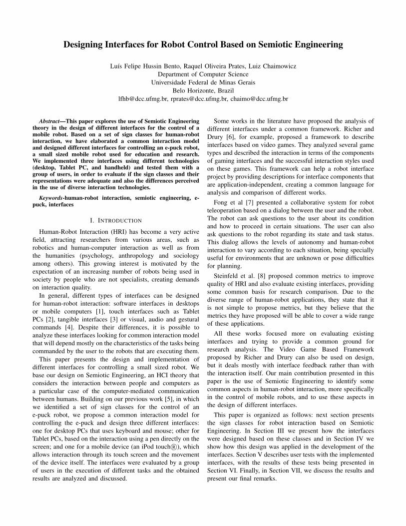
Fig. 1. Part of the MoLIC interaction diagram designed.
Figure 1 shows part of the interaction diagram designed,depicting the communication about controlling the robot(interaction regarding initialization and connection has beenleft out of Figure 1). Notice that the diagram represents theturns in conversation between user and system. The systemis represented by the letter ’s’ and the user by ’u’, and thediagram depicts whose turn it is and what the conversation isabout. The interaction model describes the possible topics ofconversation as being: Robot Status - system communicatesrobot status and users can talk about how they want to controlthe robot movement (moving or teleoperating); Move Robot- defining points for it to go; and Drive Robot - controllingits movement (real time). During the robot’s movement itis also possible to “talk” about this movement. Notice thatthe interaction diagram describes the main topics of theuser-system interaction, which does not change according tothe technology in which the interface will be implemented.
Once the interaction diagram was created, the next stepwas to define the sign conceptual schema. In this MoLIC
TABLE ISIGN CONCEPTUAL SCHEMA AND IT ATTRIBUTES.
Attribute DescriptionIdentification Sign nameSign-typecontent
Description: Meaning of the signSource:where the sign comes from, for instancewhether it is from the domain or is a newsign created by the application; Content type:which consists of the values it may assume
Sign-tokenvalue
Possible values sign types may assume andrestrictions that may apply
Breakdownpreventionand recoverymechanisms
Potential communicative breakdowns thatmay be associated to a sign, for instanceentering an invalid date
Sign-expression
Emitter: who determines the value of thesign, being the system and/or the user;Expression type: what kind of elements touse to express the sign, for instance textedit or simple choice; Default expression:whether the values has a default or not
component we specified what sign types would be necessaryto express the conversation described. The sign classeswere added to the sign attributes, which originally were:identification, description, sign-type content, sign-tokenvalue, breakdown prevention and recovery mechanisms,and sign-expression. Table I briefly describes each of theseattributes.
TABLE IICLASSES AND SIGNS
Identification Description ClassConnectionstatus
Sign(s) that should displayinterface-robot connect status
Operation
Interactionmode
Sign(s) to indicate currentinteraction mode (driving orwaypoints)
Operation
Position Sign(s) to show where the robot is PositioningOrientation Sign(s) showing the direction the
robot is facingPositioning
Speed Sign(s) to indicate the robot speed MovementDirection Sign(s) to show the robot movement
directionMovement
Path Sign(s) to indicate the path whichthe robot will follow
Movement
Destination Sign(s) showing robot movementdestination
Movement
Obstacleproximity
Sign(s) showing how close therobot is from obstacles
Environment
Surroundings Sign(s) to show what is around therobot
Environment
Photographedimage
Sign(s) showing what wasphotographed by the robot
Environment
Table II shows part of the sign schema generated for theinteraction model, namely the attributes: identification, signclass and description. Notice that there are no signs related tothe Task class. The reason for this is that in this context thegoal was just to control the e-puck and the task was generic– that is any task that could be performed by the e-puck.Thus, no representation of task aspects was included in theinteraction. At any rate, if that had not been the intention,the fact that no Task class signs were represented could lead
the designer to consider whether that was the case (as inthis context) or not. If not, he would then reflect about whatsigns should be part of the system-user interaction and towhich topics of conversation (in the interaction diagram) theyshould be related to. This example shows how class signscould lead the designer to reflect about specific aspects ofthe human-robot interaction model. Therefore, we may arguethat adding the sign classes have improved MoLIC’s ability tosupport human-robot interaction designers in their reflectionsand consequently decisions about the system being designed.
IV. DEVELOPING THE INTERFACES
As mentioned, based on the interaction model described inthe previous section, three interfaces were developed usingdiferent technologies: desktop, Tablet PC, and handheld. Forthe Tablet PC we chose a HP Compaq Tablet PC modeltc4400. As for the mobile device, we chose the iPod touch R©,a device with many resources, such as multitouch, internalaccelerometer and wi-fi, among others.
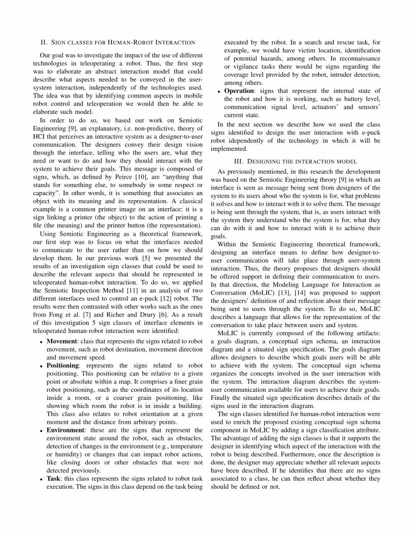
Fig. 2. The e-puck robot.
The interfaces were developed to control an e-puck robot.The e-puck [12], shown in Fig. 2, is a small sized (7cmdiameter) differential robot designed by EPFL – EcolePolytechnique Federale de Lausanne – for educational andresearch purposes. It has a 16-bit dsPIC processor, bluetoothcommunication, a VGA camera, a 3D accelerometer, eightinfrared sensors, a speaker, three microphones and a LED ringaround it. The e-puck project was created to develop a robotwith a clean mechanical structure that is simple to understand;has the ability to cover a large range of activities; is smalland easy to operate; resistant to student use; provides cheapand simple maintenance; and has low price for large scaleuses [15]. Also, the e-puck was developed under the “openhardware” license, allowing anyone to use the documentationand develop extensions to it. To program it, an open sourcelibrary written in C is available, allowing control over therobot features.
The connection with the robot and the basic sensing andactuation commands were programmed using the PlayerFramework [16]. In order to allow the interfaces to bedeveloped using any programming language and to allow
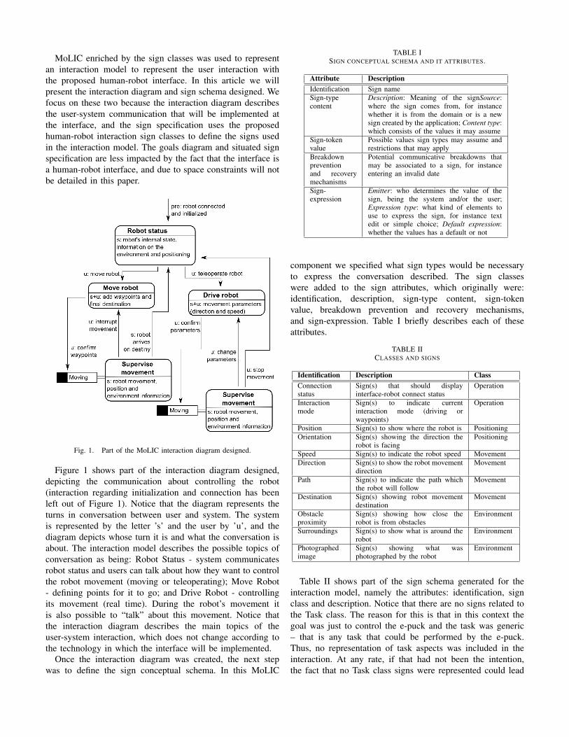
easier wireless communication via wi-fi, a server was created.This way, there was no need to port the e-puck driver to theprogramming languages used in each interface. The interfacescomunicate with the robot by sending messages to this server,which used the player e-puck driver [17] to send commandsto the robot via bluetooth.
We also used the server to solve another problem: e-puckpositioning. The e-puck has only odometry sensors to calculateits position, which is an unreliable source since it can generatecumulative errors. Within the server, we used the silvver [17]library to locate the e-puck more precisely. This library usescomputer vision to locate a geometric pattern placed on thetop of the robot. In our tests, we used three overhead camerason the test arena to locate the e-puck. The server also providesthe location map and the e-puck camera feed to the interface.This architecture is shown in Fig. 3.
Fig. 3. System architecture.
A. Desktop PC interface
The desktop PC interface was developed on a Windowsplatform, using .NET framework with C#. It contains a singlescreen, as seen on Fig. 4, showing the map with the currentposition of the robot and the waypoints, if they are given usingthe mouse. The user can use the buttons on the top of themap to add and remove waypoints by clicking on the desiredlocations on the map and to command the robot to follow thegiven waypoints. If the user chooses to drive the robot directly,there is an area on the bottom-right where he can click andhold/drag to make the robot move forward and backwards,steering right or left if desired. The linear and angular speeds
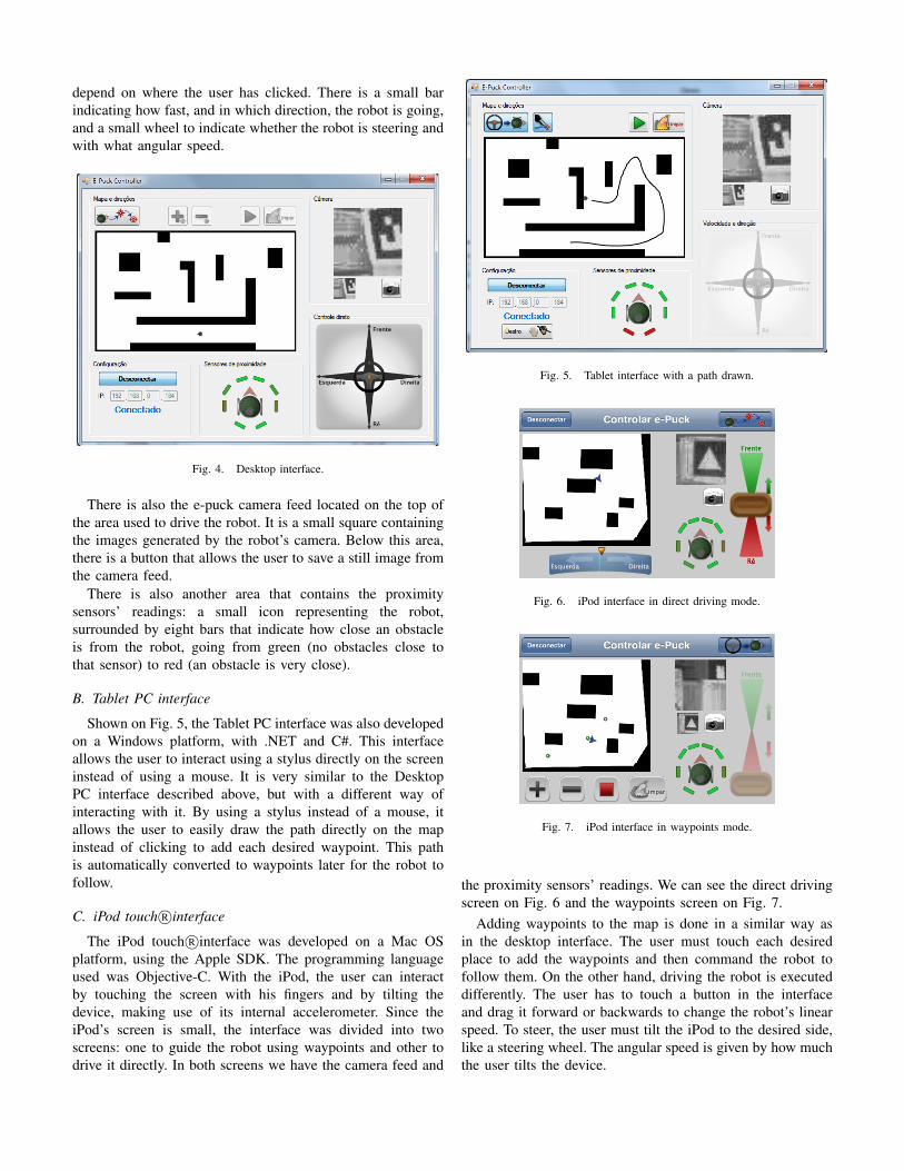
depend on where the user has clicked. There is a small barindicating how fast, and in which direction, the robot is going,and a small wheel to indicate whether the robot is steering andwith what angular speed.
Fig. 4. Desktop interface.
There is also the e-puck camera feed located on the top ofthe area used to drive the robot. It is a small square containingthe images generated by the robot’s camera. Below this area,there is a button that allows the user to save a still image fromthe camera feed.
There is also another area that contains the proximitysensors’ readings: a small icon representing the robot,surrounded by eight bars that indicate how close an obstacleis from the robot, going from green (no obstacles close tothat sensor) to red (an obstacle is very close).
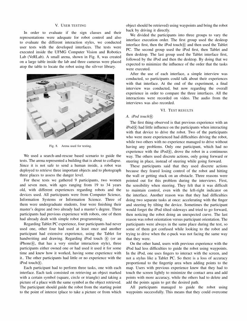
B. Tablet PC interface
Shown on Fig. 5, the Tablet PC interface was also developedon a Windows platform, with .NET and C#. This interfaceallows the user to interact using a stylus directly on the screeninstead of using a mouse. It is very similar to the DesktopPC interface described above, but with a different way ofinteracting with it. By using a stylus instead of a mouse, itallows the user to easily draw the path directly on the mapinstead of clicking to add each desired waypoint. This pathis automatically converted to waypoints later for the robot tofollow.
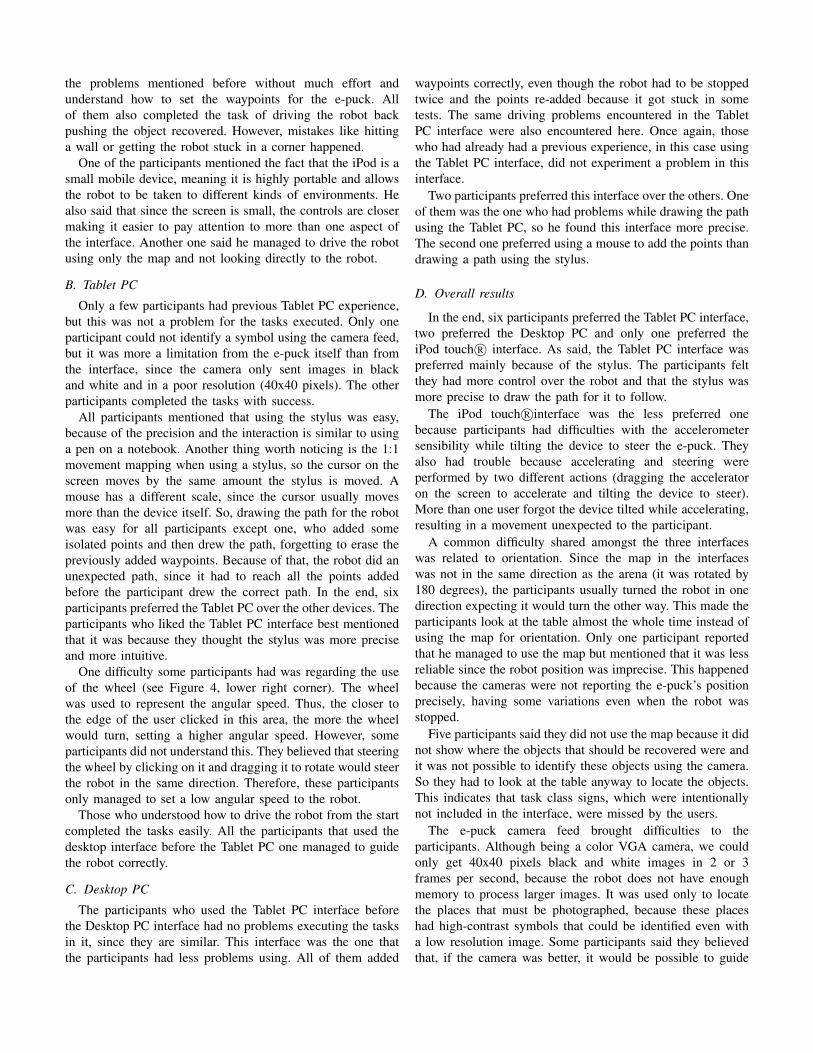
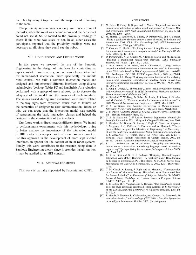
C. iPod touch R©interface
The iPod touch R©interface was developed on a Mac OSplatform, using the Apple SDK. The programming languageused was Objective-C. With the iPod, the user can interactby touching the screen with his fingers and by tilting thedevice, making use of its internal accelerometer. Since theiPod’s screen is small, the interface was divided into twoscreens: one to guide the robot using waypoints and other todrive it directly. In both screens we have the camera feed and
Fig. 5. Tablet interface with a path drawn.
Fig. 6. iPod interface in direct driving mode.
Fig. 7. iPod interface in waypoints mode.
the proximity sensors’ readings. We can see the direct drivingscreen on Fig. 6 and the waypoints screen on Fig. 7.
Adding waypoints to the map is done in a similar way asin the desktop interface. The user must touch each desiredplace to add the waypoints and then command the robot tofollow them. On the other hand, driving the robot is executeddifferently. The user has to touch a button in the interfaceand drag it forward or backwards to change the robot’s linearspeed. To steer, the user must tilt the iPod to the desired side,like a steering wheel. The angular speed is given by how muchthe user tilts the device.
V. USER TESTING
In order to evaluate if the sign classes and theirrepresentations were adequate for robot control and alsoto evaluate the different interaction styles, we conducteduser tests with the developed interfaces. The tests wereexecuted inside the UFMG Computer Vision and RoboticsLab (VeRLab). A small arena, shown in Fig. 8, was createdon a large table inside the lab and three cameras were placedatop the table to locate the robot using the silvver library.
Fig. 8. Arena used for testing.
We used a search-and-rescue based scenario to guide thetests. The arena represented a building that is about to collapse.Since it is not safe to send a human inside, a robot wasdeployed to retrieve three important objects and to photographthree places to assess the danger level.
For these tests we gathered 9 participants, two womenand seven men, with ages ranging from 19 to 34 yearsold, with different experiences regarding robots and thedevices used. All participants were from Computer Science,Information Systems or Information Science. Three ofthem were undergraduate students, four were finishing theirmaster’s degree and two already had a master’s degree. Threeparticipants had previous experience with robots, one of themhad already dealt with simple robot programming.
Regarding Tablet PC experience, four participants had neverused one, other four had used at least once and anotherparticipant had extensive experience, using the Tablet forhandwriting and drawing. Regarding iPod touch R© (or aniPhone R©, that has a very similar interaction style), threeparticipants either owned one or had used it used it for sometime and knew how it worked, having some experience withit.. The other participants had little or no experience with theiPod touch R©.
Each participant had to perform three tasks, one with eachinterface. Each task consisted on retrieving an object markedwith a certain symbol (square, circle or triangle) and taking apicture of a place with the same symbol as the object retrieved.The participant should guide the robot from the starting pointto the point of interest (place to take a picture or from which
object should be retrieved) using waypoints and bring the robotback by driving it directly.
We divided the participants into three groups to vary theinterface execution order. The first group used the desktopinterface first, then the iPod touch R© and then used the TabletPC. The second group used the iPod first, then Tablet andthen desktop. The last group used the Tablet interface first,followed by the iPod and then the desktop. By doing that weexpected to minimize the influence of the order that the taskswere executed.
After the use of each interface, a simple interview wasconducted, so participants could talk about their experienceswith that interface. At the end of the experiment, a finalinterview was conducted, but now regarding the overallexperience in order to compare the three interfaces. All theinteractions were recorded on video. The audio from theinterviews was also recorded.
VI. TEST RESULTS
A. iPod touch R©The first thing observed is that previous experience with an
iPod R© had little influence on the participants when interactingwith that device to drive the robot. Two of the participantswho were more experienced had difficulties driving the robot,while two others with no experience managed to drive withouthaving any problems. Only one participant, which had noexperience with the iPod R©, drove the robot in a continuousway. The others used discrete actions, only going forward orsteering in place, instead of steering while going forward.
These participants said that they used discrete actionsbecause they feared losing control of the robot and hittingthe wall or getting stuck on an obstacle. Three reasons werepointed out for this problem during the interviews. First,the sensibility when steering. They felt that it was difficultto maintain control, even with the left-right indicator onthe interface. Another reason was that they had difficultiesdoing two separate tasks at once: accelerating with the fingerand steering by tilting the device. Sometimes the participantwould forget the iPod tilted sideways and tried to go forward,then noticing the robot doing an unexpected curve. The lastreason was robot orientation versus participant orientation. Theparticipants were always in the same place during the test, sosome of them got confused while looking to the robot andtrying to drive when the e-puck was not facing the same waythat they were.
On the other hand, users with previous experience with theiPod had less difficulties to guide the robot using waypoints.In the iPod, one uses fingers to interact with the screen, andnot a stylus like a Tablet PC. So there is a loss of accuracyproportional to the fingertip area when adding points to themap. Users with previous experience knew that they had totouch the screen lightly to minimize the contact area and addpoints with more accuracy, while the others had to delete andadd the points again to get the desired path.
All participants managed to guide the robot usingwaypoints successfully. This means that they could overcome
the problems mentioned before without much effort andunderstand how to set the waypoints for the e-puck. Allof them also completed the task of driving the robot backpushing the object recovered. However, mistakes like hittinga wall or getting the robot stuck in a corner happened.
One of the participants mentioned the fact that the iPod is asmall mobile device, meaning it is highly portable and allowsthe robot to be taken to different kinds of environments. Healso said that since the screen is small, the controls are closermaking it easier to pay attention to more than one aspect ofthe interface. Another one said he managed to drive the robotusing only the map and not looking directly to the robot.
B. Tablet PC
Only a few participants had previous Tablet PC experience,but this was not a problem for the tasks executed. Only oneparticipant could not identify a symbol using the camera feed,but it was more a limitation from the e-puck itself than fromthe interface, since the camera only sent images in blackand white and in a poor resolution (40x40 pixels). The otherparticipants completed the tasks with success.
All participants mentioned that using the stylus was easy,because of the precision and the interaction is similar to usinga pen on a notebook. Another thing worth noticing is the 1:1movement mapping when using a stylus, so the cursor on thescreen moves by the same amount the stylus is moved. Amouse has a different scale, since the cursor usually movesmore than the device itself. So, drawing the path for the robotwas easy for all participants except one, who added someisolated points and then drew the path, forgetting to erase thepreviously added waypoints. Because of that, the robot did anunexpected path, since it had to reach all the points addedbefore the participant drew the correct path. In the end, sixparticipants preferred the Tablet PC over the other devices. Theparticipants who liked the Tablet PC interface best mentionedthat it was because they thought the stylus was more preciseand more intuitive.
One difficulty some participants had was regarding the useof the wheel (see Figure 4, lower right corner). The wheelwas used to represent the angular speed. Thus, the closer tothe edge of the user clicked in this area, the more the wheelwould turn, setting a higher angular speed. However, someparticipants did not understand this. They believed that steeringthe wheel by clicking on it and dragging it to rotate would steerthe robot in the same direction. Therefore, these participantsonly managed to set a low angular speed to the robot.
Those who understood how to drive the robot from the startcompleted the tasks easily. All the participants that used thedesktop interface before the Tablet PC one managed to guidethe robot correctly.
C. Desktop PC
The participants who used the Tablet PC interface beforethe Desktop PC interface had no problems executing the tasksin it, since they are similar. This interface was the one thatthe participants had less problems using. All of them added
waypoints correctly, even though the robot had to be stoppedtwice and the points re-added because it got stuck in sometests. The same driving problems encountered in the TabletPC interface were also encountered here. Once again, thosewho had already had a previous experience, in this case usingthe Tablet PC interface, did not experiment a problem in thisinterface.
Two participants preferred this interface over the others. Oneof them was the one who had problems while drawing the pathusing the Tablet PC, so he found this interface more precise.The second one preferred using a mouse to add the points thandrawing a path using the stylus.
D. Overall results
In the end, six participants preferred the Tablet PC interface,two preferred the Desktop PC and only one preferred theiPod touch R© interface. As said, the Tablet PC interface waspreferred mainly because of the stylus. The participants feltthey had more control over the robot and that the stylus wasmore precise to draw the path for it to follow.
The iPod touch R©interface was the less preferred onebecause participants had difficulties with the accelerometersensibility while tilting the device to steer the e-puck. Theyalso had trouble because accelerating and steering wereperformed by two different actions (dragging the acceleratoron the screen to accelerate and tilting the device to steer).More than one user forgot the device tilted while accelerating,resulting in a movement unexpected to the participant.
A common difficulty shared amongst the three interfaceswas related to orientation. Since the map in the interfaceswas not in the same direction as the arena (it was rotated by180 degrees), the participants usually turned the robot in onedirection expecting it would turn the other way. This made theparticipants look at the table almost the whole time instead ofusing the map for orientation. Only one participant reportedthat he managed to use the map but mentioned that it was lessreliable since the robot position was imprecise. This happenedbecause the cameras were not reporting the e-puck’s positionprecisely, having some variations even when the robot wasstopped.
Five participants said they did not use the map because it didnot show where the objects that should be recovered were andit was not possible to identify these objects using the camera.So they had to look at the table anyway to locate the objects.This indicates that task class signs, which were intentionallynot included in the interface, were missed by the users.
The e-puck camera feed brought difficulties to theparticipants. Although being a color VGA camera, we couldonly get 40x40 pixels black and white images in 2 or 3frames per second, because the robot does not have enoughmemory to process larger images. It was used only to locatethe places that must be photographed, because these placeshad high-contrast symbols that could be identified even witha low resolution image. Some participants said they believedthat, if the camera was better, it would be possible to guide
the robot by using it together with the map instead of lookingto the table.
The proximity sensors sign was only used once in one ofthe tasks, when the robot was behind a box and the participantcould not see it. So he looked to the proximity readings toassess if the robot was stuck or not. In all other cases theparticipants reported that the proximity readings were notnecessary at all, since they could see the robot.
VII. CONCLUSIONS AND FUTURE WORK
In this paper we proposed the use of the SemioticEngineering in the design of interfaces for controlling ane-puck robot. Based on a group of sign classes identifiedfor human-robot interaction, more specifically for mobilerobot control, we built a common interaction model anddesigned and implemented different interfaces using diversetechnologies (desktop, Tablet PC and handheld). An evaluationperformed with a group of users allowed us to observe theadequacy of the model and the nuances of each interface.The issues raised during user evaluation were more relatedto the way signs were expressed rather than to failures onthe semantics of designer to user communication. Based onthis, we can argue that the interaction model was capableof representing the basic interaction classes and helped thedesigner in the construction of the interfaces.
Our future work is direct towards different fronts. We intendto perform more experiments with this methodology, tryingto better analyze the importance of the interaction modelin HRI under a developer point of view. We also want touse this approach in the development of more sophisticatedinterfaces, in special for the control of multi-robot systems.Finally, this work contributes to the research being done inSemiotic Engineering theory since it provides insight on howit may be applied to an HRI context.
VIII. ACKNOWLEDGMENTS
This work is partially supported by Fapemig and CNPq.
REFERENCES
[1] M. Baker, R. Casey, B. Keyes, and H. Yanco, “Improved interfaces forhuman-robot interaction in urban search and rescue,” in Systems, Manand Cybernetics, 2004 IEEE International Conference on, vol. 3, oct.2004, pp. 2960 – 2965.
[2] M. Skubic, D. Anderson, S. Blisard, D. Perzanowski, and A. Schultz,“Using a qualitative sketch to control a team of robots,” in Robotics andAutomation, 2006. ICRA 2006. Proceedings 2006 IEEE InternationalConference on, 2006, pp. 3595–3601.
[3] C. Guo and E. Sharlin, “Exploring the use of tangible user interfacesfor human-robot interaction: a comparative study,” in Procs of CHI ’08.ACM, 2008, pp. 121–130.
[4] D. Perzanowski, A. C. Schultz, W. Adams, E. Marsh, and M. Bugajska,“Building a multimodal human-robot interface,” IEEE IntelligentSystems, vol. 16, no. 1, pp. 16–21, 2001.
[5] L. F. H. Bento, R. O. Prates, and L. Chaimowicz, “Using semioticinspection method to evaluate a human-robot interface,” in Proceedingsof the 2009 Latin American Web Congress (la-web 2009), ser. LA-WEB’09. Washington, DC, USA: IEEE Computer Society, 2009, pp. 77–84.
[6] J. Richer and J. L. Drury, “A video game-based framework for analyzinghuman-robot interaction: characterizing interface design in real-timeinteractive multimedia applications,” in Procs of HRI’06. ACM, 2006,pp. 266–273.
[7] T. Fong, S. Grange, C. Thorpe, and C. Baur, “Multi-robot remote drivingwith collaborative control,” in IEEE International Workshop on Robot-Human Interactive Collaboration, 2001.
[8] A. Steinfeld, T. W. Fong, D. Kaber, M. Lewis, J. Scholtz, A. Schultz,and M. Goodrich”, “Common metrics for human-robot interaction,” in2006 Human-Robot Interaction Conference. ACM, March 2006.
[9] C. S. de Souza, The Semiotic Engineering of Human-ComputerInteraction (Acting with Technology). The MIT Press, March 2005.
[10] C. S. Peirce, Collected Papers of Charles Sanders Peirce, Hartshorne,Ed. Harvard University Press, 1931.
[11] C. S. de Souza and C. F. Leitao, Semiotic Engineering Methods forScientific Research in HCI. Morgan & Claypool Publishers, June 2009.
[12] F. Mondada, M. Bonani, X. Raemy, J. Pugh, C. Cianci, A. Klaptocz,S. Magnenat, J.-C. Zufferey, D. Floreano, and A. Martinoli, “The e-puck, a Robot Designed for Education in Engineering,” in Proceedingsof the 9th Conference on Autonomous Robot Systems and Competitions,P. J. Goncalves, P. J. Torres, and C. M. Alves, Eds., vol. 1, no. 1.Portugal: IPCB: Instituto Politecnico de Castelo Branco, 2009, pp.59–65. [Online]. Available: http://www.est.ipcb.pt/robotica2009/
[13] S. D. J. Barbosa and M. G. de Paula, “Designing and evaluatinginteraction as conversation: a modeling language based on semioticengineering,” Springer Verlag Lecture Notes in Computer Science LNCS,vol. 2844, 2003.
[14] B. S. da Silva and S. D. J. Barbosa, “Designing Human-ComputerInteraction With MoLIC Diagrams – A Practical Guide,” Departamentode Ciencia da Computacao, PUC-Rio, Brasil, In C.J.P. de Lucena (ed.),Monografias em Ciencia da Computacao, 12 2007, 12/07, ISSN 0103-9741.
[15] C. M. Cianci, X. Raemy, J. Pugh, and A. Martinoli, “Communicationin a Swarm of Miniature Robots: The e-Puck as an Educational Toolfor Swarm Robotics,” in Simulation of Adaptive Behavior (SAB-2006),Swarm Robotics Workshop, ser. Lecture Notes in Computer Science(LNCS), 2007, pp. 103–115.
[16] B. P. Gerkey, R. T. Vaughan, and A. Howard, “The player/stage project:Tools for multi-robot and distributed sensor systems,” in In Proceedingsof the 11th International Conference on Advanced Robotics, 2003, pp.317–323.
[17] R. Garcia, P. Shiroma, L. Chaimowicz, and Campos, “A framework forswarm localization,” in Proceedings of VIII SBAI – Brazilian Symposiumon Intelligent Automation, October 2007, (In portuguese).