DESIGNING A HIGH LEVEL CO-OPERATE NETWORK …
113
DESIGNING A HIGH LEVEL CO-OPERATE NETWORK INFRASTRUCTURE WITH MPLS CLOUD A PROJECT REPORT Submitted by B. Sarat Sasank (316126510125) K.S.D. Kuladeep Kumar (316126510144) B. Shraavan Kummar (316126510129) V. Balu Veeren (316126510118) K. Priyanka (316126510142) in partial fulfillment for the award of the degree of BACHELOR OF TECHNOLOGY IN COMPUTER SCIENCE and ENGINEERING Under the esteemed guidance of Mr.G.V.Eswara Rao, M.Tech Assistant Professor DEPARTMENT OF COMPUTER SCIENCE AND ENGINEERING ANIL NEERUKONDA INSTITUTE OF TECHNOLOGY & SCIENCES (AUTONOMOUS) (Permanently Affiliated to Andhra University)
Transcript of DESIGNING A HIGH LEVEL CO-OPERATE NETWORK …

DESIGNING A HIGH LEVEL CO-OPERATE
NETWORK INFRASTRUCTURE WITH MPLS
CLOUD
A PROJECT REPORT
Submitted by
B. Sarat Sasank (316126510125)
K.S.D. Kuladeep Kumar (316126510144)
B. Shraavan Kummar (316126510129)
V. Balu Veeren (316126510118) K. Priyanka (316126510142)
in partial fulfillment for the award of the
degree of
BACHELOR OF TECHNOLOGY
IN
COMPUTER SCIENCE and ENGINEERING
Under the esteemed guidance of
Mr.G.V.Eswara Rao, M.Tech
Assistant Professor
DEPARTMENT OF COMPUTER SCIENCE AND ENGINEERING
ANIL NEERUKONDA INSTITUTE OF
TECHNOLOGY & SCIENCES (AUTONOMOUS)
(Permanently Affiliated to Andhra University)

SANGIVALASA: VISAKHAPATNAM - 531162
DEPARTMENT OF COMPUTER SCIENCE AND ENGINEERING
ANIL NEERUKONDA INSTITUTE OF TECHNOLOGY AND SCIENCES
(UGC AUTONOMOUS)
(Affiliated to AU, Approved by AICTE and Accredited by NBA & NAAC with ‘A’ Grade)
Sangivalasa, bheemili mandal, visakhapatnam dist.(A.P)
BONAFIDE CERTIFICATE
This is to certify that the project report entitled “Designing a High-level Cooperate Network
Infrastructure with MPLS Cloud” submitted by B.Sarat Sasank (316126510125),
K.S.D.Kuladeep Kumar (316126510144), B. Shraavan Kummar (316126510129), V.Balu veeren
(316126510118), K.Priyanka (316126510142) in partial fulfillment of the requirements for the
award of the degree of Bachelor of Technology in Computer Science Engineering of Anil
Neerukonda Institute of technology and sciences (A), Visakhapatnam is a record of bonafide
work carried out under my guidance and supervision.
Project Guide Head of the Department
MR.G. V. ESWARA RAO Dr. R. SIVARANJANI
ASSISTANTPROFESSOR HEAD OF THE DEPARTMENT
DEPT. OF CSE DEPT.OF CSE

DECLARATION
We, B.Sarat Sasank (316126510125), K.S.D.Kuladeep Kumar (316126510144), B. S
hraavan Kummar (316126510129),V.Balu veeren (316126510118), K.Priyanka
(316126510142) of final semester B.Tech., in the department of Computer Science and
Engineering from ANITS, Visakhapatnam, hereby declare that the project work entitled
“DESIGNING A HIGH LEVEL CO-OPERATE NETWORK INFRASTRUCTURE
WITH MPLS CLOUD” is carried out by us and submitted in partial fulfillment of the
requirements for the award of Bachelor of Technology in Computer Science
Engineering , under Anil Neerukonda Institute of Technology & Sciences(A) during the
academic year 2016-2020 and has not been submitted to any other university for the
award of any kind of degree.
B. Sarat Sasank (316126510125)
K.S.D. Kuladeep Kumar (316126510144)
B. Shraavan Kummar (316126510129)
V. Balu Veeren (316126510118)
K. Priyanka (316126510142)

ACKNOWLEDGEMENT
We would like to express our deep gratitude to our project guide MR.G.V.ESWARA RAO
Designation, Department of Computer Science and Engineering, ANITS, for his/her guidance
with unsurpassed knowledge and immense encouragement. We are grateful to Dr. R.
SIVARANJANI, Head of the Department, Computer Science and Engineering, for providing us
with the required facilities for the completion of the project work.
We are very much thankful to the Principal and Management, ANITS, Sangivalasa, for their
encouragement and cooperation to carry out this work.
We also thank our project coordinator Mrs.K.S.Deepthi for her support and encouragement .We
express our thanks to all teaching faculty of Department of CSE, whose suggestions during
reviews helped us in accomplishment of our project. We would like to thank all non-teaching
staff(Mrs.B.V.Udaya Lakshmi) of the Department of CSE, ANITS for providing great
assistance in accomplishment of our project.
We would like to thank our parents, friends, and classmates for their encouragement throughout
our project period. At last but not the least, we thank everyone for supporting us directly or
indirectly in completing this project successfully.
PROJECT STUDENTS
B. Sarat Sasank (316126510125)
K.S.D. Kuladeep Kumar (316126510144)
B. Shraavan Kummar (316126510129)
V. Balu Veeren (316126510118) k.Priyanka (316126510142)

CONTENTS
TITLE Page no.
Abstract 1
Key words 1
List of figures 2
1. Introduction
1.1 Introduction about OSPF,HSRP,VLAN’S 5 1.2 Motivation for the work 6 1.3 problem statement 6
1.4 organization of the thesis 7
2. Literature Survey 8
3. Methodologies
3.1 MPLS 9
3.2 Routing protocol 15
3.3 BGP 18
3.4 OSPF 23
3.5 FHRP 25
3.6 HSRP 27
3.7 VLAN’S 30
3.8 ROAS 32
3.9 Access control lists 37
3.10 NAT 40
3.11 Policy routing 44
3.12 Layer-3 Switching 46
4. Proposed System 48 4.1 System Architecture
5. Experimental analysis and Results
5.1 System configuration 49 5.1.1 Software requirement
5.1.2 Hardware requirements
5.2 Implementation 52 5.3 Sample code 55
5.4 Output screenshots 58
6. Conclusion and future work 61
6.1 Conclusion 6.2 Future Work
7. References 62
8. Appendices 64

1
ABSTRACT
Networking is defined as the act of making contact and exchanging information with
other people, groups and institutions to develop mutually beneficial relationships, or to access
and share information between computers. There are also multiple devices or mediums which
helps in the communication between two different devices which are known as Network
devices like Router, Switch, Hub, Bridge. For further security and communication purposes
the routing protocols and access lists are being used. The routing protocol OSPF has gained a
wide popularity for its scope of varied implementation. Controlling the traffic flow through
different ISP’s makes the real sense of providing the security at enterprise level. The other
security measures like NAT has become very vital in an organizational communication that
helps in preventing the data breach in a large scale.
KEYWORDS
Multi-Protocol Label Switching (MPLS), Open Shortest Path First (OSPF), Virtual Local
Area Network (VLAN), Wide Area Network (WAN), Firs Hop Redundancy Protocol
(FHRP), Hot Standby Redundancy Protocol (HSRP), Access Control Lists (ACLs), Network
Address Translation (NAT), Time Division Multiplexing (TDM), Border Gateway Protocol
(BGP), Link State Data Base (LSDB

1
LIST OF FIGURES
Branch office Design

2
Main Office Design
MPLS
VLAN

3
L3-SWITCHING

4
HSRP
5
1.INTRODUCTION
In earlier days of networking there aren’t many risks of security attacks and data thefts since
the resources of using internet are very less and capitals are high as a result of which a very
few people have the cognizance of using the internet but as a consequence of globalization
every individual now have the access to the internet and number of people using it has
ameliorated drastically. Along with the users, the traffic that is generated has been increasing
every day which becomes the major threat in preserving security. Instead of providing the
very strict rules and norms for a feeble network it is better to design a well-defined and robust
network. So, the network design plays a fundamental role in providing security for any
organization being the cardinal level of limiting illegal access and authorizations to
organizations. The recent survey conducted across the globe has shown that more than 80
percent of the security violations and outbreaks are caused within the organization than
outside which depicts the importance of strong network design.
1.1 INTRODUCTION ABOUT OSPF,HSRP,VLAN’S:
The implementation of routing protocols like OSPF provides packet flow to the external
networks and succor in keeping different areas that are connected to the backbone area and
summarizations for minimal traffic congestions. The HSRP is used for the sub second
network convergence in case of the first hop failure by providing the backup gateway making
the network uptime to the maximum extent. The VLANs are configured for the inner
organizational security by restricting the data transferring to particular subnets and allowing it
to flow under certain circumstances. The NAT also plays an important role in network
security and from data breach protection by hiding the private addresses and showcasing the
public addresses. The type of traffic flow which is the key factor to be examined for illegal
entry of packets into the network is provided by the ACLs. The provision of high bandwidth
for productive work is accomplished by using route-maps which is called policy-based
routing. We can be able to provide high security for a network by using all the technologies
in the right way and in the right proportions.
The MPLS technology is mainly used for the reliable transmissions and also to allow the
minimum packet dropouts from the transmissions. Apart from MPLS, we can also use
employ Frame Relay (FR) for this task but it is not so often used nowadays and incompetent

6
when compared to the MPLS. The MPLS promises a better bandwidth, speed, scalability,
Quality of Service (QOS) and traffic control making it a first choice for selecting among the
point to point connections. The MPLS forwards the packets by swapping the labels of
incoming and outgoing packets and their ports. This forwarding is based on the labels which
are dependent not only on the ip addresses but also on paths, services management,
congestion, QoS and other factors which makes it different from the traditional ip forwarding.
All the label switch routers (LSR) which are present in the cloud are not of the same kind.
Some give priority for the data, some for the voice and some for the video forwarding. This
way MPLS makes its selection and switches the packets accordingly.
1.2 MOTIVATION FOR THE WORK:
The one of biggest motivations is employing the mod technology in the domain to achieve
the preconceived goals that were set to abate the bad effects. Using highly sophisticated
technological techniques that are prevalent to create a most secured network design by
eliminate all the possibilities which begets the illegal intrusions is ever been a paramount
aspect especially in our present ages of constant petulance in impeachments of numerous
resources. This benign task has been accomplished along with the succor of other pervasive
protocols which are considered substantial in the domain
1.3 PROBLEM STATEMENT:
The substandard network design makes organizations prone to many security attacks and can
lead to infor-mation breach since there are many people around us watching and monitoring
every possibility to break into the network. So it becomes indispensable to build a network
with highly sophisticated techniques and integrating them congruent to the network design.
So, we design a network by implementing the technologies that are considered to be the finest
in their respective areas thereby providing security to the network from its base. In this
project, we first discuss the protocols and other leading edges that are incorporated in detail
for the network design, further their implementations with perspicuous outputs. This
document details about MPLS, the technology created over TDM for reliable
telecommunication protection along with how efficiently OSPF, HSRP, VLANs, ACLs, and
their implicit functionalities are utilized to achieve the intent.

7
1.4 ORGANISATION OF THE THESIS:
Chapter 1 discusses a brief introduction to the project.
Remaining chapters of the book describes the following:
Chapter 2 specifies literature survey, different existing methods for implementing the
technique.
Chapter 3 describes the methodology and basic terminology related to the project.
Chapter 4 specifies a popular existing system and how the drawbacks are eliminated in our
proposed work.
Chapter 5 describes the architecture of our proposed work.
Chapter 6 specifies the implementation along with sample code.
Chapter 7 discusses the functional, non-functional and implementation requirements that are
identified during the course of work.
Chapter 8 describes the experimental procedure with some sample output screenshots.
Chapter 9 specifies the conclusion and our future work.

2. LITERATURE SURVEY
8
There are many research works related to the technologies and protocols that are used in the
network design. They have provided the structure and usage of technology severally in their
distinctive works like OSPF, MPLS, BGP, FHRP. One cannot use the best metrics in the
technology to make a good network design. The selection of the extent to which these
technologies to be used is purely and solely depends on the type of network that is designed.
One cannot presume or possess a standard network design but must use the knowledge of
them to design the network of their own in the way they require for the organization. This
document is about designing a good network using MPLS as a main and effective use of
other technologies to build a high-end secure network according to the requirement and
congruence with one another that is not susceptible to the attacks.

3.METHODOLOGIES
9
3.1 MPLS(Multi-Protocol Label Switching)
MPLS works on packets and each packet has labels which have properties related to IP
forwarding. The protocols results with IP switched paths are called LSP. The Label Switch
Router (LSR) can follow specific topological routes and other constraints such as resource
availability and explicit routes by using IP routing protocols and then set up the paths across
the network. The traffic is mapped onto LSP and then the MPLS follows these predefined
paths and forwards the data by label swapping. In label swapping the MPLS monitors the
incoming label and input port and swap it with outgoing label and output port and this is
independent of the encapsulated IP header fields. Another important MPLS aspect is that the
LSPs can work on many link layers types such as frame relay, Ethernet and ATM.
All LSRs are not equal they vary in their capabilities like paths, services management,
congestion and network failure. LSR specify these capabilities and shows the implementation
of MPLS. Some LSRs are designed and programmed for the traditional best-effort services
related to internet level services, some LSRs are specifically designed to handle business
class IP, video, or voice services. For the purpose of fully utilizing of the capabilities of an
MPLS-enabled IP network, first of all LSRs should be reliable and predictable in
performance behaviour and must support the TE and TE functions in fully advanced range.
a. Forwarding Equivalent Class
The MPLS forwarding technology is based on classification. It classifies the packets into a
category that fall in the same forwarding mode; this category is called Forwarding Equivalent
Class (FEC). In MPLS the packets are treated the same that are related to same FEC. The
Packets are grouped together that have identical source and destination address, protocol
type, VPN source port, destination port, or any combinations of these.
b. Labels
A label is a fixed-length short identifier and it is used to identify a specific FEC. It is of local
significance. There may be a case of more than one label that is called label stack. The label
contains no topology information. A label contains four bytes. The format of MPLS label is

10
There is the following information that is contained by MPLS 32 bit label field:
• 20 bit label (a number) • the experimental field of 3 bit which is used to carry the value of
IP precedence • the bottom of stack indicator of 1 bit which is denoted here as S and it
indicates whether this is the last label before the IP header • 8 bit TTL
c. Label Switch router (LSR):
In MPLS network the basic element is LSR. The LSR is made up of a forwarding plane and a
control plane. Exchanging routing information and labels is part of control field and
forwarding of packets (LSR and Edge LSR) or cells (ATM LSR and ATM edge LSR) is the
part of forwarding plane.
The routing table and a label mapping table for LSRs is created by routing protocols such as
OSPF, ISIS. The ingress LSR or edge router receives a packet, examines its FEC and then
adds a label to the packet. The transit LSR forwards the packet according to its label and the
label forwarding table. The Egress LSR takes off the label and forward the packet .

11
THE ROLE OF IP/MPLS TECHNOLOGY IN NEXT GENERATION NETWORKS
Now businesses everywhere are using the Internet and to fulfill their business requirements
they have a need of value-added services from their service providers. The new businesses
focus for Internet service providers has new requirements that include reliability,
performance and the ability to deliver differentiated levels of services. This time in the
internet the users, traffic, ISP networks and new applications are increasing continually and
due to this there is a huge demand on the Internet infrastructure and the service providers
whose networks constitute the Internet. we can now have update our networks by simply
adding more bandwidth to handle the load, but it is uncertain for the network performance,
now the time is remove these uncertainties and to focus on increasing efficiency in network
performance. The purpose of MPLS technology is to improve the reliability, and efficiency
and thereby profitability of IP networks.
A. MPLS Path towards Convergence
The switching and routing technology have strength to converge the networks. When routers
and switches are combined in a network then they can build a converged network. There are
some weaknesses in routers such as traffic management and it can be recovered by switches.
Similarly router can recover switch weaknesses e.g. switches are weak in situation of large
number of paths that can overcome by dynamic route selection ability of routers.
B. IP Networks Today
The internet service demand is increasing day by day and it is the real challenge is that how
we scale the network usage and to improve the performance with less expenses. The
managing of network changes at both routing and switching layer also requires incremental
cost and effort.
In a fully meshed router network there are many virtual circuits between routers and it seems
that each router is adjacent to all other routers. So when the number of users increase and the
number of routers will also increase. This increase in the number of adjacencies there is
created stress of scaling and stability of routing protocol.
The bandwidth requirement can also met in a number of ways which includes high capacity
ATM switches and high capacity and high performance routers. IP routers are able to
integrate a large mesh into a number of smaller meshes. MPLS provides the solution for the

12
next generation of networks by consolidating the switching and routing together between IP
and Layer 2 .
III. NETWORK CONVERGENCE OVER MPLS
MPLS is a very flexible technology in which over a single packet infrastructure it is easy to
transport voice, IPv6 and layer 2 services ATM, Frame Relay and Ethernet etc. This is the
solution to the network convergence problem that is an old problem of networks. MPLS has
capabilities like traffic engineering, fast restoration and quality of service support. These
capabilities provide each service with strict service-level agreements (SLAs) cost-efficiency.
A. Voice Transport over MPLS
Voice packets can be transported in MPLS and they do not include the overhead associated to
the typical RTP/UDP/IP encapsulation. When in case of end points e.g. between two same
gateways the voice communications are transported, before labeling and transmission the
voice packets are concatenated. This helps to reduce the encapsulation overhead.
There are different algorithms that are used to compress the RTP/UDP/IP headers in IP.
There are different protocol layers e.g. Composite IP (CIP) and Lightweight IP Encapsulation
(LIPE). In these protocol layers the concatenation may be implemented. The CIP and LIPE
concatenate voice packets above IP while Point-to-Point Protocol Multiplexing (PPPmux)
concatenates voice packets at layer 2.
There are two main solutions that are proposed in voice over MPLS for concatenation. The
first one supports transport of multiplexed voice channels, silence removal and silence
insertion descriptors, various voice compression algorithms transfer of channel associated
signaling and dialed digits. The voice packets that are concatenated are preceded by a 4-octet
header. This header includes a channel identifier, a payload type, a counter, and a payload
length field. If there is the case that the payload length is not a multiple of 4 octets, then to
make it a word (32 bits) aligned, up to 3 pad octets are included. Up to 248 calls can be
multiplexed within a single LSP identified by the outer MPLS label there can be up to 248
calls multiplexed.
The second solution addresses similar functions, but instead of defining a new voice
encapsulation like , it reuses components of the ATM Adaptation Layer type 2 (AAL2),
defined for transport of several variable bit rate voice and data streams multiplexed over an
ATM connection.

13
IV. IP-MPLS TRAFFIC ENGINEERING
Using Traffic Engineering (TE) methodologies traffic flows can be controlled in such a way
that network performance and resource utilization can be optimized. TE is helpful to ISPs to
route network traffic in an organized manner that they can provide the best service to their
customers in terms of delay and throughput.
MPLS is an advanced forwarding scheme, using MPLS routing mechanism extends with
respect to path controlling and packet forwarding. A header is included in each MPLS packet
which contains 20-bit label in non-ATM networks, 3-bit Experimental field, 1-bit label stack
indicator and 8-bit TTL field. While considering ATM Networks, MPLS header consists of a
label encoded in VCI/VPI field. Label Switching Router (LSR) examines the label and
perhaps the experimental field while forwarding packets in the network [10].
MPLS traffic engineering accounts for the amount of traffic flow while determining explicit
routes across the network backbone and for link bandwidth. MPLS provides a dynamic
adaptation mechanism which has a complete solution to TE a backbone. Fault occurrence is
minimized in the backbone with the help of this mechanism, even though several primary
paths are precalculated offline. RFC 2702 discusses the requirements for TE in MPLS
networks.
A tunnel is automatically establishes and maintains by MPLS TE across the backbone using
Resource Reservation Protocol (RSVP), for given tunnel a path can be determined at any
instant of time by using the network resources and tunnel resource requirements such as
bandwidth. If the traffic flow is so large that it can’t be carried out by a single tunnel then
multiple tunnels between a given ingress and egress can be configured to load shared the
traffic among them.
A. IOS mechanisms for MPLS TE
IOS mechanisms for MPLS Traffic Engineering as discussed in are as follows:
• Label Switched Path (LSP) tunnels, which are signaled through RSVP, with TE extensions.
LSP tunnels are represented as IOS tunnel interfaces, have a configured destination, and are
unidirectional.

14
• A link-state IGP (such as Intermediate System to Intermediate System (IS-IS)) with
extensions for the global flooding of resource information, and extensions for the automatic
routing of traffic onto LSP tunnels as appropriate.
• An MPLS TE path calculation module that determines paths to use for LSP tunnels. • An
MPLS traffic engineering link management module that does link admission and
bookkeeping of the resource information to be flooded.
• Label switching forwarding, which provides routers with a Layer 2-like ability to direct
traffic across multiple hops as directed by the resource-based routing algorithm.
MPLS TE supports preemption between TE LSPs of different priorities. Each TE LSP has a
setup and a holding priority, which can range from zero (best priority) through seven (worst
priority). Recent advancements in MPLS technology open new possibilities to illustrate the
limitations of IP systems regarding TE. Though MPLS is a simple technology which based
on classical label swapping paradigm. It introduced the sophisticated control capabilities that
advance the TE function in IP Networks.
V. TRANSITIONING TO IPV6 USING IP-MPLS NETWORKS
IPv6 is in the market for quite some time but NAT extended the life of IPv4, the deployment
of IPv6 is delayed due to lack of motivation and that most vendors did not support IPv6.
However in the recent years large number of different types applications (e.g. Point to Point)
are developed and NAT is no longer sufficient. Internet users are increased enormously due
to DSL and now a day’s not only PCs can connect to the internet but 3G mobile devices also
use internet. So the use of IPv6 is now boosted, vendors now support IPv6, and ISPs deploy
IPv6 services.
MPLS system can be used to forward IPv6 traffic in the IPv4 network, the complete scenario
is illustrated in Figure 4 . The steps are:
• From Router-B to Router-A, a tunnel is built by advertising the following IPv4 address:
“12.128.76.23”.
• Router-A assign a green label (four-octet MPLS label with label value) to the IP
“12.128.76.23”.
• Then IPv6 packet is forwarded.
• The green label is added instead of encapsulating the IPv6 packet in IPv4 format, and
Router-A determines that packet must be forwarded to Router-B.
• Router-C replaces the green label with the purple label.
• Router-D replaces the purple label with the blue label.

15
• Router-B strips and send IPv6 packet to its destination.
3.2 ROUTING PROTOCOL
It is important to learn the routes not only those which are directly connected to a router but
also those that are obliquely connected. The former one's information is obtained from the
interface particulars and configurations. For the later ones, we need routing protocols to
accomplish the task. The routing protocols allow communication between different routers
and help them in exchanging their information with the others.
The routing protocols mainly work by the principle of exchanging hello messages. These
multicast messages not only help in establishing the relationship between the routers but also
in sustaining the relationship even after the connection was established. The routing protocols
are broadly classified into two categories. They are link-state routing protocols and distance-
vector routing protocols. The usage of link-state routing protocols is preferred to distance-
vector as they contain the complete knowledge on all the routes present in the network
whereas the distance-vector just possesses information only about the directly connected
routes. However, the preference is done on the design of the topology.
Dynamic routes are routes learned via routing protocols. Routing protocols are configured on
routers with the purpose of exchanging routing information. There are many benefits of using
routing protocols in your network, such as:
• Unlike static routing, you don’t need to manually configure every route on each router in
the network. You just need to configure the networks to be advertised on a router directly
connected to them.
• If a link fails and the network topology changes, routers can advertise that some routes
have failed and pick a new route to that network.
Types of routing protocols
There are two types of routing protocols:
1. Distance vector (RIP, IGRP)
2. Link state (OSPF, IS-IS)

16
Distance vector protocols
As the name implies, distance vector routing protocols use distance to determine the best path
to a remote network. The distance is something like the number of hops (routers) to the
destination network.
Distance vector protocols usually send the complete routing table to each neighbor (a
neighbor is directly connected router that runs the same routing protocol). They employ some
version of Bellman-Ford algorithm to calculate the best routes. Compared with link state
routing protocols, distance vector protocols are easier to configure and require little
management, but are susceptible to routing loops and converge slower than the link state
routing protocols. Distance vector protocols also use more bandwidth because they send
complete routing table, while the link state procotols send specific updates only when
topology changes occur.
RIP and EIGRP are examples of distance vector routing protocols.
Link state protocols
Link state routing protocols are the second type of routing protocols. They have the same
basic purpose as distance vector protocols, to find a best path to a destination, but use
different methods to do so. Unlike distance vector protocols, link state protocols don’t
advertise the entire routing table. Instead, they advertise information about a network toplogy
(directly connected links, neighboring routers…), so that in the end all routers running a link
state protocol have the same topology database. Link state routing protocols converge much
faster than distance vector routing protocols, support classless routing, send updates using
multicast addresses and use triggered routing updates. They also require more router CPU
and memory usage than distance-vector routing protocols and can be harder to configure.
Each router running a link state routing protocol creates three different tables:
• neighbor table – the table of neighboring routers running the same link state routing
protocol.
• topology table – the table that stores the topology of the entire network.
• routing table – the table that stores the best routes.

17
Shortest Path First algorithm is used to calculate the best route. OSPF and IS-IS are
examples of link state routing protocols.
Difference between distance vector and link state routing protocols
The following table summarizes the differences:

18
3.3 BGP (Border Gateway Protocol)
Border Gateway Protocol (BGP) is a only standardized Exterior Gateway Protocol (EGP)
designed to exchange the routing and reach ability information of the destination node
between multiple Autonomous Systems (AS) over the Internet. The protocol is classified as a
path vector protocol, but is sometimes also called as a distance vector routing protocol. The
Border Gateway Protocol (BGP) does not use the Interior Gateway Protocol (IGP) metrics,
but it makes routing decisions based on paths, network policies and rule-sets configured by a
network administrator. The Border Gateway Protocol plays a major role in the overall
operation of the Internet and is involved in making core routing decisions.
Border Gateway protocol is the most widely used Exterior Gateway Protocol (EGP) by the
ISP (Internet Service Provides) because BGP allows fully decentralized routing. When BGP
runs between two peers in same Autonomous System (AS) which is called as IBGP (Interior
Border Gateway Protocol) and when it runs between two different Autonomous Systems it is
called as EBGP (Exterior Border Gateway Protocol).Routers on the border of one
Autonomous System to exchanging information with another AS are called border or edge
routers .
➢ BGP routing in a single AS
The Internet consists of thousands of Autonomous Systems (ASes)—networksthat are each
owned and operated by a single institution. BGP is the routing protocolused to exchange
reachability information across ASes. Usually each ISP operates one AS, though some ISPs
may operate multiple ASes for business reasons (e.g. to provide more autonomy to
administrators of an ISP’s backbones in the United States and Europe) or historical reasons
(e.g. a recent merger of two ISPs). Non-ISP businesses (enterprises) may also operate their
own ASes so as to gain the additionalrouting flexibility that arises from participating in the
BGP protocol. Compared to enterprise networks, ISPs usually have more complex policies
arising from the fact that they often have several downstream customers, connect to certain
customers in multiple geographic locations, have complex traffic engineering goals, and run
BGP on internal routers (rather than just border routers as enterprises often do). Although
some of the observations we make apply to enterprise networks, our core focus in this paper
is on ISP networks. In this section, we describe BGP from the standpoint of a single AS,
describing first the protocol that transmits routes from one AS to another, then the decision

19
process used to choose routes, and finally the mechanisms used at routers to implement
policy.
➢ Exchanging routing state
Figure-1
Figure-1 shows a simple BGP network. BGP sessions are established between border routers
that reside at the edges of an AS and border routers in neighboring ASes. These sessions are
used to exchange routes between neighboring ASes. Border routers then distribute routes
learned on these sessions to nonborder (internal) routers as well as other border routers in the
same AS using internal-BGP (iBGP). In addition, the routers in an AS usually run an Interior
Gateway Protocol (IGP) to learn the internal network topology and compute paths from one
router to another. Each router combines the BGP and IGP information to construct a
forwarding table that maps each destination prefix to one or more outgoing links along
shortest paths through the network to the chosen border router.
BGP is a relatively simple protocol with a few salient features. First, BGP is an incremental
protocol, where after a complete routing table is exchanged between neighbors, only changes
to that information are exchanged. These changes may be new route advertisements, route
withdrawals, or changes to route attributes. Second, BGP is a path-vector protocol where
advertisements contain a list of ASes used to reach the destination. Third, routes are
advertised at the prefix level, so an AS would send a separate update for each of its reachable
prefixes. Fourth, BGP update messages may contain several fields, including a list of prefixes
being advertised, a list of prefixes being withdrawn, and a list of route attributes that describe
various characteristics of each advertised route. An ISP implements its policies by modifying
route attributes and changing the way routers react to advertisements with certain route
attributes, as discussed below.

20
➢ Selecting a route at a router
A BGP router in an ISP may have several alternate routes to reach a particular destination. In
the absence of policy, the router would choose the route with the minimum pathlength, with
some arbitrary way to break ties between routes with the same pathlength. However, in order
to give operators greater control over route selection, several additional attributes were added
to advertisements, allowing a router to alter its decisions based on the values of these
attributes.
The end result is the BGP decision process, consisting of an ordered list of attributes across
which routes are compared, as shown in Table 1. The router goes down the list, comparing
each attribute in the list across the two routes. If the routes have different values for the
attribute, the router chooses the one that has the more desirable attribute, otherwise it moves
on to compare the next attribute in the list. The route that is chosen is used by the router to
forward packets. The ordering of attributes allows the operator to influence various stages of
the decision process. For example, the Local Preference (LocalPref) is the first step in the
decision process. By changing LocalPref, an operator can force a route with a longer AS path
to be chosen over a shorter one. As another example, the Multi-Exit Discriminator (MED) is
typically used by two ASes connected by multiple links to indicate which peering link should
be used to reach the AS advertising the attribute. MED was placed lower in the decision
process as this allows an ISP to override these suggestions, e.g. by setting LocalPref. Using a

21
strict ordering of attributes in the decision process simplifies policy expression and makes it
easier to predict the outcome of making configuration changes. While some vendors allow
operators to disable certain steps in the decision process, they typically do not permit the
operators to put the steps in a different order. Hence some policies that violate this ordering
(e.g. ignore AS path length, or first choose lowest MED then highest LocalPref) may require
various hacks which can complicate router configuration and lead to unforeseen side effects.
There are different locations where a route attribute can be set by policy: (a) Locally, for
example LocalPref is an integer value set at and propagated throughout the local AS and
filtered before sending to neighboring ISPs. (b) Neighbor, for example the MED attribute is
typically used by two ASes connected by multiple links to indicate which peering link should
be used to reach the AS advertising the MED attribute, and is not used to compare routes
through two different next-hop ASes. (c) Neither: some attributes, for example whether the
route was learned through an external BGP (eBGP) neighbor or from an internal router
speaking BGP (iBGP), are set by the protocol and cannot be changed.
The collective results of the decision process across routers is to produce a set of equally
good border routers for each prefix, where each router in the set is equivalent according to the
first four steps of the decision process that compare BGP attributes. Each internal router then
chooses the router in that set that is closest according to the Interior Gateway Protocol (IGP)
path cost to reach that border router. For example in Figure 1, suppose prefix 6.0.1.0/24 is
reachable to B via both A and C, but B’s LocalPref is set higher for routes through A. The set
of equally good border routers would then contain R1 and R2, and each router in B would
select the route that was closest exit point (lowest IGP cost): ra and R1 would choose the
route through R1, and all other routers would choose the route through R2.
There are three steps a router uses to process route advertisements. First import policy is
applied to determine which routes should be filtered and hence eliminated from
consideration, and may append or modify attributes. Next, the router applies the decision
process to select the most desirable route. Finally, an export policy is applied which
determines which neighbors the chosen route will be exported to. An ISP may implement its
policy by controlling any of these three steps, i.e., by modifying import policy to filter routes
it doesn’t want to use, modifying route attributes to prefer some routes over others, or by
modifying export policy to avoid providing routes for certain neighbors to use. In addition, an
ISP can modify attributes of routes it advertises, which can influence how its neighbors
perform route selection.
➢ Configuring local policies

22
There are three classes of “knobs” that can be used to control import and export policies:
1. Preference influences which BGP route will be chosen for each destination prefix.
Changing preference is done by adding/deleting/modifying route attributes in BGP
advertisements. Table 1 shows which attributes can be modified during import to control
preference locally, and which can be modified during export to change how much a neighbor
prefers the route.
2. Filtering eliminates certain routes from consideration and also controls who they will be
exported to. Filtering may be applied both before preference (inbound filtering) or after
preference (outbound filtering). Filtering is done by instructing routers to ignore
advertisements with attributes matching certain specified values or ranges.
3. Tagging allows an operator to associate additional state with a route, which can be used to
coordinate decisions made by a group of routers in an AS, or to share context across AS
boundaries. The key mechanism is the community attribute , a variable-length string used to
tag routes. The community attribute is a highly expressive mechanism, lending itself to
support a wide variety of complex policies that are difficult to express through other means.
For example, one community value might affect how the receiving router sets LocalPref,
while another might cause the route to be filtered at another router. However, its
expressiveness gives potential for misconfiguration, which is exacerbated by the fact that
community attributes usage is not standardized.
An ISP implements its policies by applying

23
3.4 OSPF (Open Shortest Path First)
OSPF which stands for Open Shortest Path First is a link-state classless routing protocol that
is being widely used in organizations for its many advantages. It maintains a topological table
also know as LSDB (Link State Data Base) and uses Dijkstra's shortest path algorithm for its
route selection process. It works well on both simple and advanced network topologies that
make it feasible for everyone. OSPF unlike RIP uses bandwidth and delay as the metrics for
the route selection process and can provide equal load balancing.
In OSPF, forming the neighbor relation follows some sequences of steps. First, the router
must be given a router-id manually or else the highest interface ip-address will be considered
as its router-id. The interfaces that are connected are to be added to the link-state database
and then hello messages are exchanged between the routers. The hello messages must have
the same hello and dead timers, areas, subnet mask, authentication passwords for the
successful exchange.
Succeeding the hello message transfer, the routers are related and are said to be in a master-
slave relationship and form neighbors. This is followed by required information transfer
between the routers from their databases which are acknowledged and reviewed. Finally,
after these steps, the neighbors are synchronized and said to be in FULL STATE.
The presence of too many routers in the topology results in network loop when an update
occurs because in the link-state routing the updates are being transmitted to every router that
creates a network loop. To control this, a router per ethernet will be selected and is assigned
the role of transmitting the route updates thereby controlling the chances of a loop. This
selected router is known as Designated Router (DR) and a backup for this router is also
selected which is called Backup Designated Router (BDR). The DR selection can be done
manually by giving more priority or dynamically by selecting the one having the highest
router-id. The DR maintains the 2-way relation with the other routers.
The ospf being a link-local routing protocol contains a large database of routes which
sometimes leads to overload and congestion within the network. so, in ospf protocol, the
network is divided into small groups called areas that are numbered from ‘0’ to facilitate the

24
administration, confinement of routing updates, resource optimization, and traffic control.
0 15 30 45 60
OSPF
RIP
IGRP
EIGRP
ROUTER UPDATES
Area 0 is known as the BACKBONE area and every other area must be connected to the
backbone area.
The routers present at the border of two areas are called AREA BORDER ROUTER (ABR)
where we can summarize the routes to provide the feature ‘confinement of routing
information’. The routers present at the border to two autonomous systems (end of companies
ospf) are called AUTONOMOUS SYSTEM BOUNDARY ROUTER (ASBR). Only ABR
and ASBR routers are used to summarize the routes but no other router can perform the job in
ospf. However, it is known that every area must be connected to area 0 but it can be overruled
by connecting to other areas (say area x) by using virtual-links. The virtual-links logically
connects the area (x) to the area 0 and spoofs that it is physically connected to area 0.
25
3.5 FHRP (First-Hop Redundancy Protocol)
FHRP stands for First Hop Redundancy Protocol, works in layer 3 of the OSI model. It is
created typically to provide redundancy for a gateway that provides the internet to a network.
The gateway router is the only way that a network or subnet is connected to the internet, the
event of failure makes the complete network into isolation.
So when a failover occurs to the active gateway then the redundant gateway must become
active and perform the job of gateway until the original gateway comes back to the line. The
routers in the group must possess the same ip address for the redundancy operation but since
it is not possible to have the same ip in a subnet we keep a virtual ip that is different from
their individual ip for this operation. There are 8 types of FHRP of which HSRP, VRRP,
GBP are eminent.
Understanding First Hop Redundancy Protocols (FHRP)
You connect a computer to your network , it boots up and automatically receives IP Address
information from the DHCP Server. There is a piece of information there called the Default
Gateway.
The Default Gateway is the router that gets us off our local subnet. Now, imagine that router
acting as the default gateway fails, suddenly we are not able to send traffic off the local
subnet, the good news is that we can add some redundancy to this scenario through the use of
a first hop redundancy protocol. This is the focus of this article Understanding First Hop
Redundancy Protocols (FHRP). Specifically we shall be looking at 3 FHRP Protocols, these
are HSRP, VRRP and GLBP.

26

27
3.6 HSRP(Hot Standby Router Protocol)
The Hot Standby Redundancy Protocol (HSRP) is a Cisco proprietary redundancy protocol
that is most popularly used among FHRP to achieve maximum percent of network uptime. It
was first created in 1994 by Cisco and it was available in two versions having the port
number 1985.
The protocol consists of default values in which the priority and decrementing values are 100
and 10 respectively. The virtual MAC address of HSRP has a form of 0000.0C07. AC XX
where 0000.0C is the Cisco vendor id, 07.AC is the HSRP id and XX is the standby group
number.
The primary gateway or the first hop is regarded as an active gateway and the secondary
gateway is considered as standby gateway in the terminology of HSRP. There will be only
one gateway that is active and others in the group will be in a standby state. The active and
standby states of a router are determined by the priority values that are assigned to them; the
highest priority router becomes the active gateway. The active router is the one that is
responsible for responding to the network requests. The HSRP group shares a single virtual ip
and Mac addresses and every router in the group (is active) responds with the same Mac
address upon the ARP requests. It is also possible to keep a separate active gateway for
separate
VLANs.
HSRP uses multicast messages to exchange the hello messages to keep track of the priority
and current values of the gateways. It sends hello messages for every 3 seconds and the hold
on or dead timer is set to 10 seconds if it crosses 10 seconds without receiving a hello
message the active router goes to the standby state by decrementing the priority value of
previous active router which will be gained by the standby to become active. Again, if the
first hop gets back from failover then the above process happens automatically making it the
active gateway.

28
Some important terms related to HSRP :
1. Virtual IP : IP address from local subnet is assigned as default gateway to all local
hosts in the network.
2. Virtual MAC address : MAC address is generated automatically by HSRP. The first
24 bits will be default CISCO address (i.e. 0000.0c). The next 16 bits are HSRP
ID (i.e. 07.ac). The next 8 bits will be the group number in hexadecimal. e.g- if the
group number is 10 then the last 8 bits will be 0a.
Example of virtual MAC address –0000.0c07.ac0a
3. Hello messages : Periodic messages exchanged by active and standby routers. These
messages are exchanged after every 3 seconds telling the state of router.
4. Hold down timer : Its default value is 10 seconds i.e roughly 3 times the value of
hello message. This timer tells us about the router that how much time will the
standby router waits for hello message if it is not received on time.
Note : If the active router fails then the standby router will become the active router.
5. Priority : By default, the priority value is 100. It is helpful when the active router
comes back after falling down, we can change the priority of standby router (which
has become the active router after the original active router is down) to less than 100
therefore it again becomes standby router.
Note : The router having higher priority will become the active router.
6. Preempt : It is a state in which the standby router automatically becomes the active
router.

29

30
3.7 VLANs(Virtual Local Area Network)
The main problem with the switches is that they cannot multicast the messages instead of
unicasting and broadcasting. It is because switches only break the collision domain but not
the broadcast domain as the routers do. In the practical world, it is not appropriate to place
routers everywhere as it adds great complexity to the network. So, it becomes paramount for
a switch to break the broadcast domain so that only a group of devices will receive the
messages i.e., multicasting.
VLAN stands for Virtual Local Area Network and works at the data-link layer. The VLANs
are regarded as broadcast domains that are divided into different logical groups that
communicate as if they were directly connected when there are in the same VLAN group.
The VLANs works on the principle of tagging, the VLAN ids are assigned to the ports, when
the messages or the data passes through the port will be appended by the VLAN id number
that the port is assigned to. So, the ports in a switch containing the same VLAN id are in one
broadcast domain. This process achieves the goal of multicasting in switches.
A switch can possess 4094 VLANs that can be used. The VLAN 1 is considered as a default
VLAN and in general, it is also regarded as native VLAN but it's not necessarily the same.
The native VLAN-id numbers must be the same for two switches that are connected for the
communication to takes place. The network management protocols like CDP, LLDP, VTP,
DTP flow through the VLAN 1 for the maintenance of the configurations.
The switch usually contains 2 types of ports which are access and trunk ports. The ports
connecting computer and switch are the access ports and two network devices are trunk ports.
If a message is to be transferred to the same VLAN in the other switch, then the connecting
link between the two switches must be made trunk as they allow the tagged traffic. The Inter-
Switch link which is a Cisco proprietary and IEEE’s 802.1q which is industry standard are
the tagging protocols.
It betides in a practical world to communicate not only within a VLAN group but between the
VLANs. Since the communication between two VLANs is regarded as the communication
between two broadcast domains this process can be accomplished in three ways in which the

31
first facet is using routers (as it breaks broadcast domain), the second facet is to make use of
l3 switching and the final facet is ROAS.
Configuration between L3 switch and VLAN.
32
3.8 ROAS(Router On A Stick)
The ROAS which is known as Router On A Stick is one of the techniques that is deployed for
inter VLAN communication. The main aim here is to break the broadcast domain that paves
the path for the communication between the VLANs. This process can be performed by
allowing different switches containing single VLAN must be connected to the separate
routing interfaces but being the router limited to a very little number of interfaces cannot
fully accommodate a large number of VLAN groups which requires more routers that in turn
increases the complexity of the network.
To mitigate this problem the sub interfaces of the router are the concept that is emerged
which logically divides the single router interface into many sub interfaces that succor in the
effective utilization of the router interfaces. Each sub interface is given an ip address to that
VLAN group and the interface between the router and the switch must be made trunk for the
flow of tagged traffic. Eventually, the communication betides between the VLANs.
Configuration of Router on a stick
Prerequisite – Access and trunk ports
Switches divide broadcast domain through VLAN (Virtual LAN). VLAN is a partitioned
broadcast domain from a single broadcast domain. Switch doesn’t forward packets across
different VLANs by itself. If we want to make these virtual LANs communicate with each
other, a concept of Inter VLAN Routing is used.
Inter VLAN Routing :
Inter VLAN routing is a process in which we make different virtual LANs to communicate
with each other irrespective of where the VLANs are present (on same switch or different
switch). Inter VLAN Routing can be achieved through a layer-3 device i.e. Router or layer-3
Switch. When the Inter VLAN Routing is done through Router the it is known as Router on
a stick.
Router On a Stick :
The Router’s interface is divided into sub-interfaces, which acts as a default gateway to their
respective VLANs.

33
Here is a topology in which there is a router and a switch and some end hosts. 2 different
VLANs have been created on the switch. The router’s interface is divided into 2 sub-
interfaces (as there are 2 different VLANs) which will acts as a default gateway to their
respective VLANs. Then router will perform Inter VLAN Routing and the VLANs will be
communicate with each other.
NOTE : Here encapsulation type dot1q is used for frame tagging between the 2 different
VLAN. When the switch forwards packet of one VLAN to another, it inserts a VLAN into
the Ethernet header.
Now, we will make 2 different VLANs on switch namely VLAN 2 and VLAN 3 giving
names HR_dept and sales_dept.
Here, we have assigned VLAN 2 to the specific switch ports fa0/1, fa0/2 and vlan 3 to fa0/3
respectively.
NOTE : int range fa0/1-2 command is used as there are more than one host present in a
single VLAN.
Now to check reachability of PC2 from PC1, we will try to PING PC2 from PC1.

34

35
From the above figures, we see that the packet is delivered to the router by the switch,
because now the broadcast domain have been divided by the different VLANs present on the

36
switch therefore, the packet will be delivered to the default gateway (as PC2 is present on
different network) and then to the destination
To enable inter-VLAN communication, you can divide a single physical interface on a router
into logical interfaces that will be configured as trunk interfaces. This scenario is called
router on a stick (ROAS) and allows all VLANs to communicate through a single physical
interface. The physical interface is divided into logical interfaces (also known as
subinterfaces), one for each VLAN.

37
3.9 ACCESS CONTROL LISTS
The access-lists are the set of rules that are configured in the router which determines
whether a packet to pass through the router or not. These access-lists are used to mitigate the
network attacks as it restricts most of the illegal traffic and promotes network security. One
can either permit or deny traffic by using their ip addresses and port numbers. Besides access
control, they also provide services like NAT, QoS, Demand Dial Routing, Policy routing,
Route filtering.
Analogous to the entry list carried by the watchman, the access-lists act like the entry list
which checks all the incoming and outgoing traffic from the router. The examination or
checking the entries in the access-lists betides from top to bottom and stop at the first match.
In general, there are two main types of access-lists they are standard ACLs and extended
ACLs. The standard access control lists work only on the source ip address and range from 1-
99, 1300-1999. The extended access control lists work on both source and destination ip
addresses and have a number range from 100-199, 2000-2699.
Why Use an ACL?
The main idea of using an ACL is to provide security to your network. Without it, any traffic
is either allowed to enter or exit, making it more vulnerable to unwanted and dangerous
traffic.
To improve security with an ACL you can, for example, deny specific routing updates or
provide traffic flow control.
As shown in the picture below, the routing device has an ACL that is denying access to
host C into the Financial network, and at the same time, it is allowing access to host D.

38
With an ACL you can filter packets for a single or group of IP address or different protocols,
such as TCP or UDP.
So for example, instead of blocking only one host in the engineering team, you can deny
access to the entire network and only allow one. Or you can also restrict the access to host C.
If the Engineer from host C, needs to access a web server located in the Financial network,
you can only allow port 80, and block everything else.
Where Can You Place An ACL?
The devices that are facing unknown external networks, such as the Internet, need to have a
way to filter traffic. So, one of the best places to configure an ACL is on the edge routers.
A routing device with an ACL can be placed facing the Internet and connecting the DMZ
(De-Militarized Zone), which is a buffer zone that divides the public Internet and the private
network.
The DMZ is reserved for servers that need access from the outside, such as Web Servers, app
servers, DNS servers, VPNs, etc.
As shown in the picture below, the design shows a DMZ divided by two devices, one that
separates the trusted zone from the DMZ and another that separates it with the Internet
(public network).

39
The router facing the Internet acts as a gateway for all outside networks. It provides general
security by blocking larger subnets from going out or in.
You can also configure an ACL in this router to protect against specific well-known ports
(TCP or UDP).
The internal router, located between the DMZ and the Trusted Zone, can be configured with
more restrictive rules to protect the internal network. However, this is a great place to choose
a stateful firewall over an ACL.
But Why is it Better to place an ACL vs. Stateful Firewall to protect the DMZ?
ACLs are directly configured in a device’s forwarding hardware, so they do not compromise
the end performance.
Placing a stateful firewall to protect a DMZ can compromise your network’s performance.
Choosing an ACL router to protect high-performance assets, such as applications or servers
can be a better option. While ACLs might not provide the level of security that a stateful
firewall offer, they are optimal for endpoints in the network that need high speed and
necessary protection.

40
3.10 NAT (Network Address Translation)
The ipv4 being a 32-bit always have a dread for ip completion. The discovery of private ip
addresses made this a long-lasting process. The public ip addresses are brought from the ISP
and the ones that are being advertised to the others on the internet. The private ip addresses
are the one which is used inside the organization and are not advertised to the outside world.
These private addresses can be the same in different organizations but cannot be identified
within the organization.
The ip addresses in ipv4 are classified into 5 classes that are used according to the topology.
Class A 10.0.0.0 – 10.255.255.255 16 million hosts on 127 networks
Class B 172.16.0.0 – 172.31.255.255 65,000 hosts on 16,000 networks
Class C 192.168.0.0 – 192.168.255.255 254 hosts on 2 million networks
Class D 224.0.0.0 — 239.255.255.255 Multicast addresses
Class E 240.0.0.0 to 254.255.255.254 For military, research purposes and future
use
The disclosure of the private ip addresses leads to huge information breach and grievous
effects on the security norms of organizations. So, it is cardinal to hide the private ip
addresses and communicate using the public ip. NAT which stands for Network Address
Translation does the job of translating private ip to the organizational public ip thereby
safeguarding the organizational policies. The translation can be done manually by assigning
the translation for prescribed addresses or dynamically by providing the pool of addresses
that can be chosen when there is more than one public ip address.

41
R1(config)# int fa0/0
R1(config-if)# ip nat inside
R1(config)# int fa0/1
R1(config-if)# ip nat outside
In the terminology of NAT, there are four types of addresses that succor in better assimilation
of the process of translation they are inside local, inside global, outside local and outside
global. These addresses help in the translation of addresses.
There are 3 types of NAT:
1. Static NAT –
In this, a single private IP address is mapped with single Public IP address, i.e., a private IP
address is translated to a public IP address. It is used in Web hosting.
Configuration –
Here is a small topology in which there is PC having IP address 192.168.1.1/24, Router R1
having IP address 192.168.1.2/24 on interface fa0/0, 12.1.1.1/24 on fa0/1 and server having
IP address 73.1.1.2/24.
Now, inside local and inside global are shown in the figure. Configuring the static NAT
through command ip nat inside source static INSIDE_LOCAL_IP_ADDRESS
INSIDE_GLOBAL_IP_ADDRESS.
R1(config)# ip nat inside source static 192.168.1.1 12.1.1.1
Now, we have configure router’s inside interface as IP NAT inside and outside interface as IP
NAT outside.
2. Dynamic NAT –
In this type of NAT, multiple private IP address are mapped to a pool of public IP address . It
is used when we know the number of fixed users wants to access the Internet at a given point
of time.
Configuration –

42
R1(config)# int fa0/0
R1(config-if)# ip nat inside
R1(config)# int fa0/1
R1(config-if)# ip nat outside
There is PC having IP address 192.168.1.1/24, Router R1 having IP address 192.168.1.2/24
on interface fa0/0, 12.1.1.1/24 on fa0/1 and server having IP address 73.1.1.2/24. Now, first configuring the access-list:
R1(config)# access-list 1 permit 192.168.1.0 0.0.0.255
Configuring the nat pool from which a public IP will be selected.
R1(config)# ip nat pool pool1 12.1.1.1 12.1.1.3 netmask 255.255.255.0
Now, enabling Dynamic NAT:
R1(config)# ip nat inside source list 1 pool pool1
At last, we have to configure router interfaces as inside or outside.
3. Port Address Translation (PAT) –
This is also known as NAT overload. In this, many local (private) IP addresses can be
translated to single public IP address. Port numbers are used to distinguish the traffic, i.e.,
which traffic belongs to which IP address. This is most frequently used as it is cost effective
as thousands of users can be connected to the Internet by using only one real global (public)
IP address.
Configuration –
Taking the same topology, There is PC1 having IP address 192.168.1.1/24, Router R1 having
IP address 192.168.1.2/24 on interface fa0/0, 12.1.1.1/24 on fa0/1 and server having IP

43
R1(config)# int fa0/0
R1(config-if)# ip nat inside
R1(config)# int fa0/1
R1(config-if)# ip nat outside
address 73.1.1.2/24.
Now, first configuring the access-list:
R1(config)# access-list 1 permit 192.168.1.0 0.0.0.255
Configuring the nat pool from which a public IP will be selected.
R1(config)# ip nat pool pool1 12.1.1.1 12.1.1.1 netmask 255.255.255.0
Here, note that the nat pool is shrunk to one ip address only and the IP address used is the
outside interface ip address of the router. If you have additional IP then you can use that also.
Now, enabling Dynamic NAT overload (PAT):
R1(config)# ip nat inside source list 1 pool pool1 overload
Or we can also use
R1(config)# ip nat inside source list 1 interface fastEthernet 0/1 overload
At last, we have to configure router interfaces as inside or outside.

44
3.11 POLICY ROUTING
In substantial organizations, some employees perform non-productive work along with
productive ones which leads to network and traffic congestions despite owning more than one
ISP. so, it becomes paramount to provide greater bandwidth for the productive work
employees than that with the entertainment ones. Of many options available, the policy
routing is the optimal choice that provides more network uptime for productive work.
The policy routing is accomplished by making the route-maps which decides the next hop or
router reach. The route-maps plays a very vital role as it identifies the type of traffic and
directs them towards the specified destination ISPs, it makes use of the access control lists for
the identification process. These access control lists are created prior to the creation of route-
maps and the traffic in the access control lists are classified either on ip addresses or port
numbers depending upon the requirement of the organization. After the ACLs are set, the
route-maps then match the traffic and provide the route for the next hop, an empty match
must be made which is very essential since any traffic that does not match with any of the
available access control lists will be treated here and directed to specific ISP.

45
What Can You Do with Policy-Based Routing?
You can use Policy Based Routing to:
• Prioritize applications by selecting high-bandwidth, low-latency links for important
applications, when more than one link is available. For example, prioritize corporate data
over a fast link and Internet browsing traffic over a slow link. (QoS)
• Load share by creating a fallback link for important traffic if the main link carrying the
important application traffic suffers an outage.
• Segregate the traffic for deep inspection or analysis. The network administrator classifies
application traffic that must go through a deep inspection and audit. Optionally, the network
administrator can route this traffic to a different device.
• Control the flow of subscriber traffic in service provider networks through traffic
management policies and rules based on subscribers’ profiles. For example, PBR can
prioritize and route certain types of application traffic to a specific routing path as per SLA or
by placing certain user requests higher than others (for example, gold, silver, bronze).
• Provide a guaranteed service-level agreement (SLA) for the delivery of the certain traffic
(such as video traffic) by ensuring that the approved traffic receives the appropriate priority,
routing, and bandwidth required to ensure the maximum user quality of experience.
• Send specific applications for WAN optimization. For instance, certain applications are
optimized for transfer over WAN links. With PBR, the network administrator can classify the
traffic based on applications, and send traffic to the WAN optimizer to speed up access to
important applications and data.

46
3.12 LAYER-3 SWITCHING
Switches are often regarded as one of the best man-made network devices base on many
grounds of which the main reason would be its hardware implementation (ASIC’s). They are
the layer 2 devices that support many incredible protocols and effective algorithms but are
limited only to the switching techniques and cannot be used to transfer packets out of the
subnet or the network.
The l3 switches perform both switching and routing and are effective when compared with
the layer 2 switches. They can utilize the routing protocols effectively and can limit the
spanning-tree failures. It contains a very less failure domain and more convergence time. It is
even faster than the router is sending packets as it works on ASIC’s but being incapable of
performing some functions like NAT which are completely software-based makes the router
still alive.
Features of a layer 3 switch
• Comes with 24 Ethernet ports, but no WAN interface.
• Acts as a switch to connect devices within the same subnet.
• Switching algorithm is simple and is the same for most routed protocols.
• Performs on two OSI layers — layer 2 and layer 3.
Purpose of a layer 3 switch
There is a ton of confusion about the use of a layer 3 switch because in a traditional setup,
routers operate at layer 3 of the OSI model while switches operate at layer 2. So, how does
this layer 3 switch fit into this model? Also, the name “layer 3 switch” causes confusion
because switches typically operate from layer 2.
Originally, layer 3 switches were conceived to improve routing performance on large
networks, especially corporate intranets. To understand the purpose, let’s step back a bit in
time to see how these switches evolved.
Layer 2 switches work well when there is low to medium traffic in VLANs. But these
switches would hang when traffic increased. So, it became necessary to augment layer 2’s
functionality. One option was to use a router instead of a switch, but then routers are slower
than switches, so this could lead to slower performance.

47
To overcome this downside, researchers thought about implementing a router within a switch.
Though technically feasible, it was not the ideal option because layer 2 switches operate only
on the Ethernet MAC frame while layer 3 handles multiple routing protocols.
Researchers felt this was too complicated, so they came up with the idea of a layer 3 switches
that acted as routers with fast forwarding done through the underlying hardware.
This is why the main difference between layer 3 switches and routers lies in the hardware. If
you were to take a peek into a layer 3 switch’s hardware, you’ll see a mix of traditional
switches and routers, except that the routers’ software logic is replaced with integrated circuit
hardware to improve performance.
Benefits of a layer 3 switch
From the above discussion, the purpose/benefits of a layer 3 switch are to:
• Support routing between virtual LANs.
• Improve fault isolation.
• Simplify security management.
• Reduce broadcast traffic volumes.
• Ease the configuration process for VLANs, as a separate router isn’t required between
each VLAN.
• Separate routing tables, and as a result, segregate traffic better.
• Simplify troubleshooting as, fixing problems in L2 layer is tedious and time-consuming.
• Support flow accounting and high-speed scalability.
• Lower network latency as a packet doesn’t have to make extra hops to go through a router.

4.PROPOSED SYSTEM
48
4.1 SYSTEM ARCHITECTURE
In this project, we first discuss the protocols and other leading edges that are incorporated in
detail for the network design, further their implementations with perspicuous outputs. This
document details about MPLS, the technology created over TDM for reliable
telecommunication protection along with how efficiently OSPF, HSRP, VLANs, ACLs, and
their implicit functionalities are utilized to achieve the intent.

5.EXPERIMENTAL ANALYSIS AND RESULTS
49
5.1 SYSTEM CONFIGURATION
5.1.1 SOFTWARE REQUIREMENTS
The software used to simulate the required networks are GNS3 in MAC OS and Packet tracer
in WINDOWS systems.
Packet Tracer
Packet Tracer is a cross-platform visual simulation tool designed by Cisco Systems that
allows users to create network toplogies and imitate modern computer networks. The
software allows users to simulate the configuration of Cisco routers and switches using a
simulated command line interface. Packet Tracer makes use of a drag and drop user interface,
allowing users to add and remove simulated network devices as they see fit. The software is
mainly focused towards Certified Cisco Network Associate Academy students as an
educational tool for helping them learn fundamental CCNA concepts.
GNS3
Graphical Network Simulator-3 (shortened to GNS3) is a network software emulator first
released in 2008. It allows the combination of virtual and real devices, used to simulate
complex networks. It uses Dynamips emulation software to simulate Cisco IOs.
GNS3 is used by many large companies including Exxon, Walmart, AT&T and NASA, and
is also popular for preparation of network professional certification exams. As of 2015, the
software has been downloaded 11 million times.

5.1.2 HARDWARE REQUIREMENTS
50
Recommended requirements
ITEM REQUIREMENT
Operating
System
Windows 7 (64 bit) or later
Processor 2 or more Logical cores
Virtualization Virtualization extensions required. You may need to
enable this via your computer's BIOS.
Memory 4 GB RAM
Storage 1 GB available space (Windows Installation is < 200
MB).
Additional
Notes
You may need additional storage for your operating
system and device images.
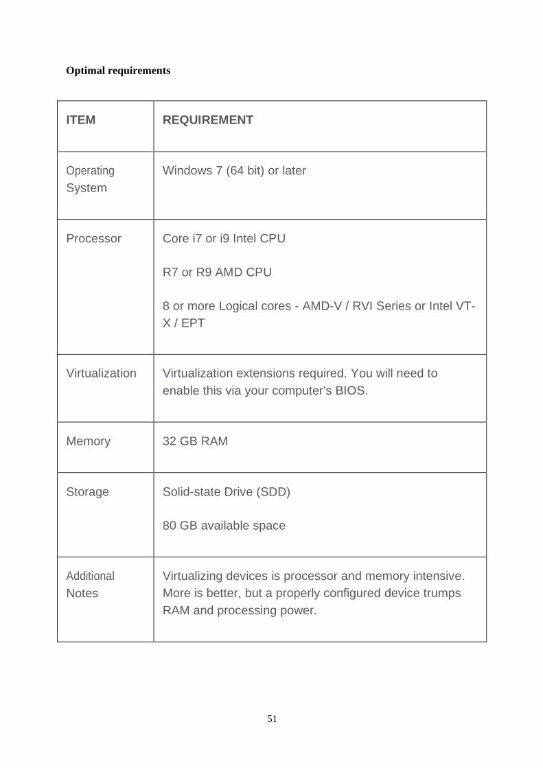
Optimal requirements
51
ITEM REQUIREMENT
Operating
System
Windows 7 (64 bit) or later
Processor Core i7 or i9 Intel CPU
R7 or R9 AMD CPU
8 or more Logical cores - AMD-V / RVI Series or Intel VT-
X / EPT
Virtualization Virtualization extensions required. You will need to
enable this via your computer's BIOS.
Memory 32 GB RAM
Storage Solid-state Drive (SDD)
80 GB available space
Additional
Notes
Virtualizing devices is processor and memory intensive.
More is better, but a properly configured device trumps
RAM and processing power.

5.2 IMPLEMENTATION
52
The network design is implemented in three modules. In the first module, we design the
branch office and its configuration. In the second module, we design the main office and in
the third module, we design the MPLS cloud and its redistribution.
Designing Branch Office
In the branch office, we implement OSPF as the routing protocol among the other routing
devices due to its flexibility and fine routing capabilities. First, we consider the branch office
as more than one-floor building each floor accommodating a router that is connected to the
switch where the end system gets access from. We also provide a WAN link between two
routers to make sure that OSPF is routing the packets to the external addresses by its entry
into its database table.
All the routers present on each floor are commonly connected to the main switch that is
placed in the server room. The main switch is singly connected to the main router which is
directly linked to the outside world or the internet. Internally we provide securities like
VLANs which makes a certain group of devices communicate and process the information.
The inter-VLAN communication is accomplished by using the ROAS, which is dividing the
physical interface of the router into sub-interfaces making them more than one logical
connection and providing the capability of breaking the broadcast domain.
Designing Main Office

53
The main office being the core of an organization it needs high-level security measures and
since the branch office is connected to it. The main office is more likely a hub, a data center
for the entire organization. We provide redundancy for the main routers since they are the
ones who transmit the crucial organization data to the branch offices. For the redundancy we
choose HSRP being its quality of keeping high network uptime. The l3 switching is
employed for high-speed routing and the other sophistications of l3 over l2 switching
techniques make the device for better transmission and routing operations.
The DHCP is also configured differentiating different VLANs present in the network for
dynamic allocation of ip and providing the flexibility of adding new end systems. We provide
two ISPs connected to the main office for providing larger data transfer and bandwidth.
Above all, the policy-based routing using route-maps makes the design more productive for
organizational works. This technique classifies the productive and lethargic work using
access control lists and thereby directing them to the specific ISPs.

54
Redistributing BGP routes
The cloud predominantly consists of routers that make use of the BGP routing protocol as it
is the only exterior gateway protocol present currently. Since being the branch offices have
OSPF as the routing protocol, the BGP routes cannot be routed because of the protocol
incompatibility. so, we perform redistribution technique by which the router on both sides
i.e., in the cloud and the branch offices learns about each other routes and are been distributed
and this process is known as redistribution. This allows very router and device to
communicate with one another.

55
5.3 SAMPLE CODE
OSPF
R1(config)# router ospf 1
R1(config-router)#router-id 4.4.4.4
R1(config-router)#network 10.1.3.1 0.0.0.255 area 0
R2(config)# router ospf 1
R2(config-router)#router-id 5.5.5.5
R2(config-router)#network 10.1.2.1 0.0.0.255 area
R1#show ip protocols
R1#show ip ospf neighbor
R1#show ip route
REDISTRIBUTION
R1(config)#router ospf 1
R1(config-router)#area 0 range 10.1.0.0 255.255.248.0
R1(config-router)#area 1 range 10.2.0.0 255.255.248.0
R2(config)#no router ospf 1
R2(config)#router rip
R2(config-router)#version 2
R2(config-router)#no auto-summary
R2(config-router)#network 10.0.0.0
R2(config-router)#network 172.16.0.0
R1(config)#router ospf 1
R1(config-router)#redistribution rip metric 20 subnets
R1(config-router)#summary-address 10.2.0.0 255.255.248.0

56
HSRP
s1(config)#int vlan
s1(config-if)#standby 1 ip 172.30.70.1
s1# show standby
s1(config-if)#standby 1 priority 110
s1(config-if)#standby 1 track fa0/1 20
s1(config-if)#standby 1 preempt
s1(config-if)#standby 1 preempt delay reload 60
s2(config)#int vlan 1
s2(config-if)#standby 1 ip 172.30.70.1
s2(config-if)#standby 1 track fa0/1 20
s2(config-if)#standby 1 preempt
s2(config-if)#standby 1 preempt delay reload 60
s2#show standby
s1(config)#int vlan 1
s1(config-if)#standby 1 timers msec 200 msec 650
s2(config)#int vlan 1
s2(config-if)#standby 1 timers msec 200 msec 650
NAT
Neo(config-std-nacl)#permit 192.168.1.0 0.0.0.25
Neo(config)#int fa0/0
Neo(config-if)#ip nat inside
Neo# reload in 5
Neo(config)#int fa0/1
Neo(config-if)# ip nat outside
Neo(config)#ip nat inside source list NAD interface fastEthernet0/1 overload

57
POLICY ROUTING
p(config)#ip access-list standard slacker
p(config-std-nacl)#permit 192.168.1.20
p(config)#p access-list extended productive
p(config-std-nacl)#permit tcp host 192.168.1.21 any eq 23/eq443
p(config)#route-map corp-policy
p(config-route-map)# match ip address slacker
p(config-route-map)#set ip next-hop 201.1.1.2

58
5.4 SCREENSHOTS
Fig:1-ROAS Sub-Interface OUTPUT
Fig:2-OSPF neighbor

59
Fig:3- NAT addresses
Fig:4-OSPF routes
Fig:5- HSRP report

60
Fig:6-Policy-based Routing using route maps

61
6.CONCLUSION AND FUTURE WORK
6.1 CONCLUSION:
The need for a well-designed network is always been a major asset for any organization.
Creating a network is not a simple task of imbibing all the available protocols, it involves
huge care, supervision, management, and confidentiality. The understanding of requirements
and availabilities of an organization and implementing the protocols that are needed in such a
way that they are compatible is the best way of building a network. In this paper, we have
assumed the ideal network requirements and selected the finest protocols like MPLS, OSPF,
HSRP, NAT, VLAN, DHCP and many more to design and provide the security to the
network.
6.2 FUTURE WORK:
The future scope for this project is substantially great. We can increase the number of routers
and switches Incase of expansion of network due to amelioration in intake of workers for an
organization. The protocols can also be shifted from one to another with ease without muting
the entire network. The present of MPLS cloud makes prodigious difference in sending the
in-numerous packets without any abberant transmission which makes a considerable highest
in speed and data availability in the future days where only ultra highs speed transmissions
are entertained. The protocols like TELNET and SSH makes the work lubricated by operating
from the home irrespective of the number of router and switches which is the utmost cardinal
incase of any pandemic outbreaks. The endorsement of access control lists and their up
gradations always become vigilant to the traffic that have been and will be elusively entering
the network from different sources.

62
7.REFERENCES
[1] TRILLIUM: Multiprotocol Label Switching (MPLS).
[2] Enovate: Multiprotocol Label Switching (MPLS).
[3] HUAWEI Technologies Proprietary: Quid way MA5200G MPLS Configuration Guide,
June 2007.
[4] Alcatel: The Role of MPLS Technology In Next Generation Networks, October 2000.
[5] Technical University of Madrid: Network Convergence over MPLS.
[6] COMPREHENSIVE MPLS VPN SOLUTIONS: Meeting the Needs of Emerging
Services with Innovative Technology. 3510324-003-EN.pdf, Jan 2010.
[7] IP Solution Center-MPLS VPN: Deploying MPLS VPN Service. White Paper, Cisco
Systems, Inc. [17] Cisco MPLS based VPNs: Equivalent to the
security of Frame Relay and ATM, White Paper. March 30, 2001.
[8] Neha Grang and Anuj Gupta, “Compare OSPF Routing Protocol with other Interior
Gateway Routing Protocols”, IJEBEA 13-147, Vol 1, pp.2-4, 2013
[9] Nikhil Hemant Bhagat,” Border Gateway Protocol –A Best Performance Protocol When
Used For External Routing than Internal Routing”, Vol 1, pp.1-2, 2012
[10] A.Alaettinoglu,C.Villamizar,E.Gerich,D.Kessens,D.Meyer, T. Bates, D. Karrenberg, M.
Terpstra, “Routing policy specifica- tion language (RPSL),” IETF RFC 2622, June 1999.
[11] T. Griffin, A. Jaggard, V. Ramachandran, “Design principles of policy languages for
path vector protocols,” in Proc. ACM SIG- COMM, August 2003.
[12] L. Subramanian, M. Caesar, C. Ee, M. Handley, Z. Mao, S. Shenker, I. Stoica, “HLP: A
next-generation interdomain routing protocol,” in Proc. ACM SIGCOMM, August 2005
[13] International Journal of Sciences: Basic and Applied Research (IJSBAR)(2012) Volume
6, No 1, pp 1-13

63
[14] https://www.ittsystems.com/access-control-list-acl/
[15] https://searchnetworking.techtarget.com/definition/Multiprotocol-Label-Switching-MPLS
[16] http://ieeexplore.ieee.org/xpl/freeabs_all.jsp?arnumber=650179
[17] http://tools.ietf.org/html/rfc3469
[18] http://www.ietf.org/rfc/rfc3037.txt
[19] http://tools.ietf.org/html/rfc3107
[20] https://doi.org/10.1109%2FICC.2005.1494347

64
8.APPENDICES

65
BASE PAPERS

1
International Journal of Sciences: Basic and
Applied Research (IJSBAR)
ISSN 2307-4531
http://gssrr.org/index.php?journal=JournalOfBasicAndApplied
Internet Protocol/MultiProtocol Label Switching (IP/MPLS)
Networks
Engr. Sajjad Hussain¹*, Engr. Muhammad Tariq Javed ² ¹Department of Electrical Engineering
²Department of Electrical Engineering
APCOMS affiliated with University of Engineering and Technology TAXILA, Pakistan
1Email:[email protected]
Abstract
This paper discusses different aspects of Multi-Protocol Label Switching (MPLS) networks. In this paper, we first
discussed MPLS in detail, the technology was developed to advance the IP networks reliability, efficiency and
controllability to meet the requirements of next generation networks and its flexibility allow the service providers to
transport converged services over a single packet infrastructure. Further we discussed the IOS mechanisms to design
an MPLS system for Traffic Engineering (TE), and IPv6 support in MPLS standards to solve the issue of IPv4 to
IPv6 transition process. This document details a MPLS Virtual Private Network (VPN), a service that offers
managed secure connectivity between corporate sites. Our discussion also includes different issues regarding
Quality of Service (QoS) in a network with MPLS.
Keywords: Internet Protocol, MultiProtocol Label Switching, (IP/MPLS) Networks.
I. OVERVIEW OF IP/MPLSNETWORKS
MPLS is an elegant solution for the problems that are present in today networks, e.g. speed, scalability, traffic
engineering and quality of service (QoS) management. MPLS is also a versatile solution to meet the requirements related to service requirements and bandwidth management for the next generation IP based core networks [1].
MPLS is an emerging technology which enhanced the capabilities of large scale IP networks and the routers
forwarding speed is also increased. Over the last few years the internet is used everywhere and is required a variety of new applications that can fulfill the business and enterprise network requirements. This variety of applications
requires the guaranteed speed and bandwidth. The exponential growth in users and volume of traffic is a great
challenge to the existing internet infrastructure. Despite these initial challenges and to meet the service and
bandwidth requirements through the next generation networks MPLS will have to play an important role in packet
forwarding, switching and routing.
* Corresponding author.
E-mail address: [email protected].
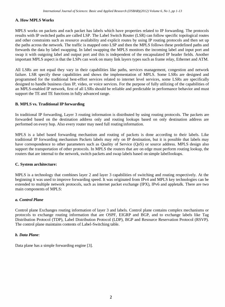
International Journal of Sciences: Basic and Applied Research (IJSBAR)(2012) Volume 6, No 1, pp 1-13
2
A. How MPLS Works
MPLS works on packets and each packet has labels which have properties related to IP forwarding. The protocols
results with IP switched paths are called LSP. The Label Switch Router (LSR) can follow specific topological routes
and other constraints such as resource availability and explicit routes by using IP routing protocols and then set up
the paths across the network. The traffic is mapped onto LSP and then the MPLS follows these predefined paths and
forwards the data by label swapping. In label swapping the MPLS monitors the incoming label and input port and
swap it with outgoing label and output port and this is independent of the encapsulated IP header fields. Another
important MPLS aspect is that the LSPs can work on many link layers types such as frame relay, Ethernet and ATM.
All LSRs are not equal they vary in their capabilities like paths, services management, congestion and network
failure. LSR specify these capabilities and shows the implementation of MPLS. Some LSRs are designed and
programmed for the traditional best-effort services related to internet level services, some LSRs are specifically
designed to handle business class IP, video, or voice services. For the purpose of fully utilizing of the capabilities of
an MPLS-enabled IP network, first of all LSRs should be reliable and predictable in performance behavior and must
support the TE and TE functions in fully advanced range.
B. MPLS vs. Traditional IP forwarding
In traditional IP forwarding, Layer 3 routing information is distributed by using routing protocols. The packets are
forwarded based on the destination address only and routing lookups based on only destination address are
performed on every hop. Also every router may need full routing information.
MPLS is a label based forwarding mechanism and routing of packets is done according to their labels. Like
traditional IP forwarding mechanism Packets labels may rely on IP destination, but it is possible that labels may
have correspondence to other parameters such as Quality of Service (QoS) or source address. MPLS design also
support the transportation of other protocols. In MPLS the routers that are on edge must perform routing lookup, the
routers that are internal to the network, switch packets and swap labels based on simple label lookups.
C. System architecture:
MPLS is a technology that combines layer 2 and layer 3 capabilities of switching and routing respectively. At the beginning it was used to improve forwarding speed. It was originated from IPv4 and MPLS key technologies can be
extended to multiple network protocols, such as internet packet exchange (IPX), IPv6 and appletalk. There are two
main components of MPLS:
a. Control Plane
Control plane Exchanges routing information of layer 3 and labels. Control plane contains complex mechanisms or protocols to exchange routing information that are OSPF, EIGRP and BGP, and to exchange labels like Tag
Distribution Protocol (TDP), Label Distribution Protocol (LDP), BGP and Resource Reservation Protocol (RSVP). The control plane maintains contents of Label-Switching table.
b. Data Plane:
Data plane has a simple forwarding engine [3].

International Journal of Sciences: Basic and Applied Research (IJSBAR)(2012) Volume 6, No 1, pp 1-13
3
Figure 1: MPLS Architecture
D. Basic Concepts:
Some basic concepts of MPLS Technology are as follows:
a. Forwarding Equivalent Class
The MPLS forwarding technology is based on classification. It classifies the packets into a category that fall in the
same forwarding mode; this category is called Forwarding Equivalent Class (FEC). In MPLS the packets are treated
the same that are related to same FEC. The Packets are grouped together that have identical source and destination
address, protocol type, VPN source port, destination port, or any combinations of these.
b. Labels
A label is a fixed-length short identifier and it is used to identify a specific FEC. It is of local significance. There
may be a case of more than one label that is called label stack. The label contains no topology information. A label
contains four bytes. The format of MPLS label is shown in Figure 2.
Figure 2: MPLS Label Format
There is the following information that is contained by MPLS 32 bit label field:
• 20 bit label (a number)
• the experimental field of 3 bit which is used to carry the value of IP precedence
• the bottom of stack indicator of 1 bit which is denoted here as S and it indicates whether this is the last
label before the IP header
• 8 bit TTL
International Journal of Sciences: Basic and Applied Research (IJSBAR)(2012) Volume 6, No 1, pp 1-13
4
c. Label Switch router (LSR):
In MPLS network the basic element is LSR. The LSR is made up of a forwarding plane and a control plane.
Exchanging routing information and labels is part of control field and forwarding of packets (LSR and Edge LSR) or
cells (ATM LSR and ATM edge LSR) is the part of forwarding plane.
Figure 3: Working of LSR in MPLS
The routing table and a label mapping table for LSRs is created by routing protocols such as OSPF, ISIS. The
ingress LSR or edge router receives a packet, examines its FEC and then adds a label to the packet. The transit LSR
forwards the packet according to its label and the label forwarding table. The Egress LSR takes off the label and
forward the packet [3].
II. THE ROLE OF IP/MPLS TECHNOLOGY
IN NEXT GENERATION NETWORKS
Now businesses everywhere are using the Internet and to fulfill their business requirements they have a need of
value-added services from their service providers. The new businesses focus for Internet service providers has new
requirements that include reliability, performance and the ability to deliver differentiated levels of services. This
time in the internet the users, traffic, ISP networks and new applications are increasing continually and due to this there is a huge demand on the Internet infrastructure and the service providers whose networks constitute the
Internet. we can now have update our networks by simply adding more bandwidth to handle the load, but it is
uncertain for the network performance, now the time is remove these uncertainties and to focus on increasing
efficiency in network performance. The purpose of MPLS technology is to improve the reliability, and efficiency
and thereby profitability of IP networks. [4]
A. MPLS Path towards Convergence
The switching and routing technology have strength to converge the networks. When routers and switches are
combined in a network then they can build a converged network. There are some weaknesses in routers such as traffic management and it can be recovered by switches. Similarly router can recover switch weaknesses e.g.
switches are weak in situation of large number of paths that can overcome by dynamic route selection ability of
routers.

International Journal of Sciences: Basic and Applied Research (IJSBAR)(2012) Volume 6, No 1, pp 1-13
5
B. IP Networks Today
The internet service demand is increasing day by day and it is the real challenge is that how we scale the network
usage and to improve the performance with less expenses. The managing of network changes at both routing and
switching layer also requires incremental cost and effort.
In a fully meshed router network there are many virtual circuits between routers and it seems that each router is
adjacent to all other routers. So when the number of users increase and the number of routers will also increase. This
increase in the number of adjacencies there is created stress of scaling and stability of routing protocol.
The bandwidth requirement can also met in a number of ways which includes high capacity ATM switches and high
capacity and high performance routers. IP routers are able to integrate a large mesh into a number of smaller
meshes. MPLS provides the solution for the next generation of networks by consolidating the switching and routing
together between IP and Layer 2 [4].
III. NETWORK CONVERGENCE OVER MPLS
MPLS is a very flexible technology in which over a single packet infrastructure it is easy to transport voice, IPv6
and layer 2 services ATM, Frame Relay and Ethernet etc. This is the solution to the network convergence problem
that is an old problem of networks. MPLS has capabilities like traffic engineering, fast restoration and quality of
service support. These capabilities provide each service with strict service-level agreements (SLAs) cost-efficiency
[5].
A. Voice Transport over MPLS
Voice packets can be transported in MPLS and they do not include the overhead associated to the typical RTP/UDP/IP encapsulation. When in case of end points e.g. between two same gateways the voice communications
are transported, before labeling and transmission the voice packets are concatenated. This helps to reduce the
encapsulation overhead.
There are different algorithms that are used to compress the RTP/UDP/IP headers in IP. There are different protocol layers e.g. Composite IP (CIP) and Lightweight IP Encapsulation (LIPE). In these protocol layers the concatenation
may be implemented. The CIP and LIPE concatenate voice packets above IP while Point-to-Point Protocol
Multiplexing (PPPmux) concatenates voice packets at layer 2.
There are two main solutions that are proposed in voice over MPLS for concatenation. The first one supports
transport of multiplexed voice channels, silence removal and silence insertion descriptors, various voice
compression algorithms transfer of channel associated signaling and dialed digits. The voice packets that are concatenated are preceded by a 4-octet header. This header includes a channel identifier, a payload type, a counter,
and a payload length field. If there is the case that the payload length is not a multiple of 4 octets, then to make it a
word (32 bits) aligned, up to 3 pad octets are included. Up to 248 calls can be multiplexed within a single LSP
identified by the outer MPLS label there can be up to 248 calls multiplexed.
The second solution addresses similar functions, but instead of defining a new voice encapsulation like , it reuses
components of the ATM Adaptation Layer type 2 (AAL2), defined for transport of several variable bit rate voice
and data streams multiplexed over an ATM connection.

International Journal of Sciences: Basic and Applied Research (IJSBAR)(2012) Volume 6, No 1, pp 1-13
6
IV. IP-MPLS TRAFFIC ENGINEERING
Using Traffic Engineering (TE) methodologies traffic flows can be controlled in such a way that network
performance and resource utilization can be optimized. TE is helpful to ISPs to route network traffic in an organized
manner that they can provide the best service to their customers in terms of delay and throughput.
MPLS is an advanced forwarding scheme, using MPLS routing mechanism extends with respect to path controlling
and packet forwarding. A header is included in each MPLS packet which contains 20-bit label in non-ATM
networks, 3-bit Experimental field, 1-bit label stack indicator and 8-bit TTL field. While considering ATM
Networks, MPLS header consists of a label encoded in VCI/VPI field. Label Switching Router (LSR) examines the
label and perhaps the experimental field while forwarding packets in the network [10].
MPLS traffic engineering accounts for the amount of traffic flow while determining explicit routes across the
network backbone and for link bandwidth. MPLS provides a dynamic adaptation mechanism which has a complete
solution to TE a backbone. Fault occurrence is minimized in the backbone with the help of this mechanism, even
though several primary paths are precalculated offline. RFC 2702 discusses the requirements for TE in MPLS
networks.
A tunnel is automatically establishes and maintains by MPLS TE across the backbone using Resource Reservation
Protocol (RSVP), for given tunnel a path can be determined at any instant of time by using the network resources
and tunnel resource requirements such as bandwidth. If the traffic flow is so large that it can’t be carried out by a
single tunnel then multiple tunnels between a given ingress and egress can be configured to load shared the traffic
among them.
A. IOS mechanisms for MPLS TE
IOS mechanisms for MPLS Traffic Engineering as discussed in [11] are as follows:
• Label Switched Path (LSP) tunnels, which are signaled through RSVP, with TE extensions. LSP tunnels are represented as IOS tunnel interfaces, have a configured destination, and are unidirectional.
• A link-state IGP (such as Intermediate System to Intermediate System (IS-IS)) with extensions for
the global flooding of resource information, and extensions for the automatic routing of traffic onto LSP tunnels as
appropriate.
• An MPLS TE path calculation module that determines paths to use for LSP tunnels.
• An MPLS traffic engineering link management module that does link admission and bookkeeping
of the resource information to be flooded.
• Label switching forwarding, which provides routers with a Layer 2-like ability to direct traffic
across multiple hops as directed by the resource-based routing algorithm.
MPLS TE supports preemption between TE LSPs of different priorities. Each TE LSP has a setup and a holding
priority, which can range from zero (best priority) through seven (worst priority). Recent advancements in MPLS
technology open new possibilities to illustrate the limitations of IP systems regarding TE. Though MPLS is a simple
technology which based on classical label swapping paradigm. It introduced the sophisticated control capabilities
that advance the TE function in IP Networks.
V. TRANSITIONING TO IPV6 USING IP-MPLS NETWORKS
IPv6 is in the market for quite some time but NAT extended the life of IPv4, the deployment of IPv6 is delayed due to lack of motivation and that most vendors did not support IPv6. However in the recent years large number of
different types applications (e.g. Point to Point) are developed and NAT is no longer sufficient. Internet users are
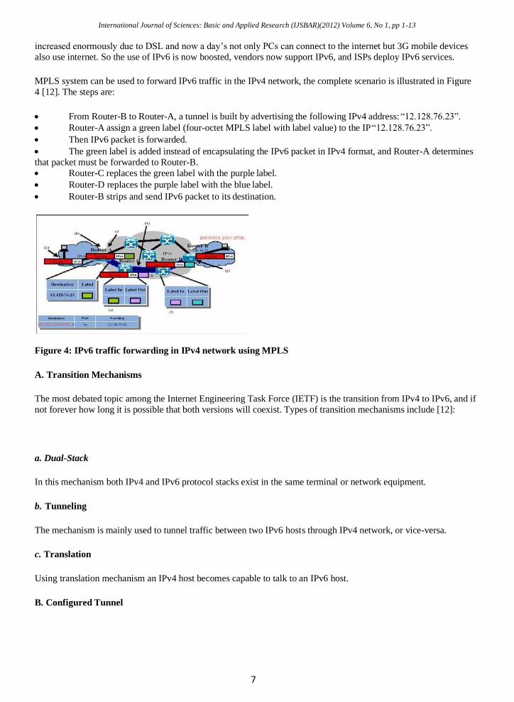
International Journal of Sciences: Basic and Applied Research (IJSBAR)(2012) Volume 6, No 1, pp 1-13
7
increased enormously due to DSL and now a day’s not only PCs can connect to the internet but 3G mobile devices
also use internet. So the use of IPv6 is now boosted, vendors now support IPv6, and ISPs deploy IPv6 services.
MPLS system can be used to forward IPv6 traffic in the IPv4 network, the complete scenario is illustrated in Figure
4 [12]. The steps are:
• From Router-B to Router-A, a tunnel is built by advertising the following IPv4 address: “12.128.76.23”.
• Router-A assign a green label (four-octet MPLS label with label value) to the IP “12.128.76.23”.
• Then IPv6 packet is forwarded.
• The green label is added instead of encapsulating the IPv6 packet in IPv4 format, and Router-A determines
that packet must be forwarded to Router-B.
• Router-C replaces the green label with the purple label.
• Router-D replaces the purple label with the blue label.
• Router-B strips and send IPv6 packet to its destination.
Figure 4: IPv6 traffic forwarding in IPv4 network using MPLS
A. Transition Mechanisms
The most debated topic among the Internet Engineering Task Force (IETF) is the transition from IPv4 to IPv6, and if
not forever how long it is possible that both versions will coexist. Types of transition mechanisms include [12]:
a. Dual-Stack
In this mechanism both IPv4 and IPv6 protocol stacks exist in the same terminal or network equipment.
b. Tunneling
The mechanism is mainly used to tunnel traffic between two IPv6 hosts through IPv4 network, or vice-versa.
c. Translation
Using translation mechanism an IPv4 host becomes capable to talk to an IPv6 host.
B. Configured Tunnel

International Journal of Sciences: Basic and Applied Research (IJSBAR)(2012) Volume 6, No 1, pp 1-13
8
Configured tunnels may be used for those sites that regularly exchange traffic to connect IPv6 hosts over current
IPv4 network, IPv4 headers are used to encapsulate the IPv6 packets. The destination of encapsulating router is the
endpoint of configured tunnel, tunneling is illustrated in Figure 5.
IPv6 hosts can communicate over the existing IPv4 network via MPLS Circuit Cross-connect mechanism, point-to-
point configured tunnel can be used for information sharing. MPLS header is used to encapsulate the IPv6 packets.
Ingress router need to be configured with the tunnel address.
Figure 5: Tunneling
MPLS platform is also reliable and economical solution to transport the IPv6 traffic on existing IPv4 network,
service providers can get benefit from this method by just enabling IPv6 on the Provider Edge (PE) router, no other
alternation needed in their existing IPv4/MPLS network (scenario is illustrated in Figure 6), this will help the service
providers to offer IPv6 services to their customers without any complexity and extra operational cost, it will also
help them to optimize their existing network by minimizing the number of IPv6 enabled devices required in their
network [13].
Figure 6: IPv6 over MPLS
The MPLS is widely noticed as a technology for the next generation Internet that provides speed and functionality in
packet forwarding. However, as a result of the rapid deployment of the MPLS technology, a rack of IPv6 support in
MPLS standards is rapidly emerging as a practical issue in the IPv4 to IPv6 transition process.
VI. COMPREHENSIVE MPLS VPN
SOLUTIONS
A. OVERVIEW OF VPN NETWORKS
The VPN market is growing on regular bases at a record pace worldwide. IDC reports that provider-provisioned
VPNs now dominate the VPN services market with VPNs deployed by over half of the multisite companies that
International Journal of Sciences: Basic and Applied Research (IJSBAR)(2012) Volume 6, No 1, pp 1-13
9
have 50 or more employees. The worldwide VPN services market reached to handsome amount of $24.4 billion in
year 2007 and is expected to climb to almost $36 billion in year 2012. In the U.S. alone, it is estimated that the VPN
market will have a 10.4 % increase over the next five years [15].
A VPN is a network in which customers from different sites are get connected on a shared network, the access and
security policies are same for VPN as a private network. VPN has a great impact on business world as a result the
growth rate of VPN infrastructure is very fast, its also provide the alternate solutions to expensive leased-lines or
circuit-switched networks [17].
To solve the scalability issue in VPN networks, a new VPN based standard protocol known as border gateway
protocol / Multiprotocol label switching (BGP/MPLS) is introduced which provide network layer VPN solutions
using BGP to carry routing information on MPLS infrastructure. Using this Layer 3 MPLS-VPN solution the
traditional Layer-2 security approach is maintained and scalability is increased due to Layer-3 routing technology.
The key benefit of the new approach is the use of Border Gateway Protocol and a set of extensions, known as BGP-
VPN, which help to maintain distinct routing and forwarding information for each VPN client. BGP use label
distribution protocol (LDP) to carry that information over MPLS infrastructure [19].
B. MPLS VPNOVERVIEW
MPLS VPN offers managed and secure connectivity among the corporate sites. MPLS VPN is the world wide de
facto standard technology which replaces the old traditional technologies such as data link layer Switch Network
and WAN.
MPLS VPN Service Providers allows the network traffic to be differentiated according to class of service (CoS)
parameters via the Internet backbone. The CoS mostly comes in Video Conferencing, Multimedia, Platinum, Gold
and Silver editions. The key advantage of CoS system is to prioritized the user traffic according to the class, hence
business critical traffic is not affected by other traffic and at the same time cost efficiency is maintained by offering
lower and economical CoS to the customer where appropriate, each CoS has it own set of SLA’s which are based on
packet loss, jitter, latency and availability of the network [14].
MPLS VPN service can be defined as [16]:
• Provider Edge (PE) - Customer Edge (CE) protocol and the protocol-specific configuration.
• Allocations of IP Addresses
• Customer Edge router should be configured in case of managed CE.
• Customer Edge routing protocols should be redistributed
• Provider Edge routing protocols should be redistributed
• Option of joining the Management VPN
• Provider Edge router must be configured for Virtual Routing and Forwarding Instance (VRF) (VRF should
be configured for maximum number of routes, and VRF routing table should me maintained for import and export
maps).
C. MPLS VPN Model
MPLS-VPN model is also known as “true peer VPN” model, traffic separation is performed at Layer-3 in this
model, and a separate IP/VPN table is maintained for forwarding purposes. A unique VRF is assigned to each
customer’s VPN to separate the traffic from different customers. This feature of MPLS-VPN is comparable to the
security of a Frame-Relay and ATM networks, because the users from different VPNs can’t see the traffic of each
other.
Forwarding in the service provider backbone is performed on the bases of labels. MPLS set these label switched
paths (LSPs), which starts and ends at the Provider Edge router while normal routing is performed on the Customer
Edge router. Packet handling is performed by PE router on its incoming interface with the help of forwarding table

International Journal of Sciences: Basic and Applied Research (IJSBAR)(2012) Volume 6, No 1, pp 1-13
10
because each incoming interface of a PE router is associated with a particular VPN. Hence a packet can be entered
in a VPN through an associated interface.
In this model no tunneling or encryption is needed for traffic separation because it is directly built into the network
itself. The route distribution is controlled by Provider Edge routers with the use of Extended BGP community
attributes. Provider Edge routers assign a label to each VPN customer route and distribute these labels with other
Provider Edge routers, which assures that packets are directed to the correct egress Customer Edge router.
During packet forwarding process two labels are used. Top label is used to direct the traffic to the correct Provider
Edge router and the second label is the indication that how the Provider Edge router should handle that particular
packet. After the completion of above process MPLS forward the packet over its backbone using dynamic IP paths
or TE paths.
For the sack of simplicity standard IP forwarding mechanism is used among the Provider Edge and Customer Edge
routers. Provider Edge router maintains a VRF forwarding table which contains only set of routes available to that
Customer Edge router. Customer Edge router is a routing peer of directly connected Provider Edge router but not a
routing peer of Customer Edge routers exists at other sites. Routing information does not exchanged directly
between the routers of different sites. The benefit of this approach is that it allows the simplification of route
configuration at individual site while considering large VPNs [17].
Figure 7: MPLS-VPN
D. Requirements of a Secure Network
MPLS/VPN based solutions and traditional layer 2 based VPN solutions can be compared on following key security requirements [17].
• Addressing and routing should be separated from each other.
• Internal structure of MPLS/VPN core network should be kept secret from outside. Just like Frame-Relay
and ATM network backbone is hidden.
• The network should be capable to resist against both Denial-of-Service (DoS) and intrusionattacks.
VI. QUALITY OF SERVICE (QOS) FOR
MPLS NETWORKS

International Journal of Sciences: Basic and Applied Research (IJSBAR)(2012) Volume 6, No 1, pp 1-13
11
The increase in the convergence of network services leads directly to the need for Quality of Service (QoS)
approach. QoS is defined as, “the ability of a network to recognize different service requirements of different
application traffic flowing through it and to comply with Service Level Agreements (SLAs) negotiated for each of
the application services, while attempting to maximize the network resource utilization”. QoS has an important role
in a multi-service network, in order to meet SLAs of different services.
If QoS is not implemented, datagrams are serviced in a network on a first-in, first-out (FIFO) basis, also known as
best-effort service. Priority is not assigned to the datagrams in such scenario, based on the type of application that
they support. As a result, differential treatment for different types of application traffic can’t possible. Therefore,
SLAs for any service other than best-effort service cannot be met. QoS maximizes network resource utilization and
optimizes revenue generation by providing priority access to network bandwidth for high-priority traffic, and by
allowing low-priority traffic to gain the bandwidth committed to high-priority traffic in the absence of high-priority
traffic.
A. MPLS QoS Architecture
MPLS does not define new QoS architecture; it uses Differentiated Services (DiffServ) architecture defined for IP
QoS. DiffServ architecture is defined in RFC2475, MPLS support for DiffServ defined in RFC3270. As MPLS is a
selected choice for next generation multiservice networks. So, MPLS QoS architecture must fit mutiservice strategy
and must be flexible and scalable [22].
At present time QoS has a key role in implementation of IP and MPLS networks. But QoS is one of the complex
features of networking. With the advancement in technology today networks support multiple applications and
multiple network services over a standalone converged network. Therefore QoS plays an important part when
network design and different operations are implemented.
Initial design of IP infrastructure supports the connectionless services for packet routing in which each packet flows
via independent path over the network to reach the destination. The design did not include TE mechanism, resource
reservation protocol and no support was implemented to meet the requirements of differentiated services. To
improve the efficiency of QoS, MPLS with label was introduced that supports connection-oriented switching. The
design of MPLS supports scaling, provides TE and rerouting mechanisms within the IP domain.
B. Working towards QoS
Several issues arise within transport services while transferring the user and control-plane data over the networks. In most cases services are provided through wired or wireless networks. One of the major issues at transport layer is
how to ensure the reliability and predictability of QoS for time critical applications over the IP network
infrastructure which is basically designed for connectionless data transport. This problem is somewhat solved by
running IP-over-ATM, and using the built-in ATM Quality of Service mechanisms. But this approach has some
limitations on carriers which do not implement ATM.
To deliver the QoS over IP infrastructure an early stage intelligence service layers schemes known as MPLS is
developed. Using MPLS service providers can define specific packet delivery paths to transport the traffic via IP networks, and there is no need of intermediate routers for packet-forwarding. Traditional routing mechanism route
the traffic via shortest and less congested path through the network, but using MPLS system the network response
time and traffic load can be balanced more efficiently [23].
In MPLS explicit paths are set to solve the QoS problem through the network. In other words we can say that MPLS
integrate the best effort delivery IP technology to connection-oriented technology like ATM. Labels are allocated to
IP packets and then packets are placed in IP frames. Then those frames are forwarded over the packet or cell-based networks and switching is done on the bases of labels instead of IP address lookup.

International Journal of Sciences: Basic and Applied Research (IJSBAR)(2012) Volume 6, No 1, pp 1-13
12
Figure 8: Working towards QoS
The label is assigned to each packet on entry into MPLS network. Routing on each node is done on the bases of
label value and incoming interface and sent out of the node by assigning a new label value on the outgoing interface.
The paths are known as LSP. LSP is a well defined path through an IP network; it provides a means for ensuring a
specified quality of service where QoS is provided by the underlying infrastructure. Due to its multiprotocol nature
MPLS support IP networks over any Layer-2 infrastructure such as ATM, packet over SONET, frame relay, Gigabit
Ethernet etc [23].
VIII. CONCLUSION
In this paper, we first discussed the general architecture of a Multi Protocol Label Switching infrastructure. The
IP/MPLS technology has essential role in next generation networks to meet the performance and the ability to
deliver differentiated levels of services in a converged services environment. Our Research experience shows that
deployment of MPLS system is feasible in a large ISP network for traffic engineering purposes. Another very useful
advantage of MPLS system is its transition process from IPv4 to IPv6. The MPLS VPN solution ensures the cost
efficiency and smooth flow of business-critical traffic simultaneously. The paper also discusses that how Quality of
Service (QoS) goals can be achieved because increase in the convergence of network services leads directly to
performance issues. The next step for the ongoing research project is to identify specific areas that will be addressed
in the near term research efforts.
REFERENCES
[1] TRILLIUM: Multiprotocol Label Switching (MPLS).
[2] Enovate: Multiprotocol Label Switching (MPLS).
[3] HUAWEI Technologies Proprietary: Quidway MA5200G MPLS Configuration Guide, June 2007.
[4] Alcatel: The Role of MPLS Technology In Next Generation Networks, October 2000.
[5] Technical University of Madrid: Network Convergence over MPLS.
[6] MPLS Forum Technical Committee: Voice over MPLS - Bearer / Transport Implementation Agreement. MPLSF
1.0, July 2001.
[7] UIT-T: Service requirements and architecture for voice services over MPLS. Rec. Y.1261, December 2002.

International Journal of Sciences: Basic and Applied Research (IJSBAR)(2012) Volume 6, No 1, pp 1-13
13
[8] MPLS/Frame Relay Alliance Technical Committee: I.366.2 Voice Trunking Format over MPLS. MPLS/FR
5.0.0, August 2003.
[9] Brunnbauer, W., Cichon, G.: AAL2 over IP for radio access networks. IEEE Globecom 2001, San Antonio,
November 2001.
[10] Xipeng Xiao, Alan Hannan, Brook Bailey. GlobalCenter Inc, A Global Crossing Company, 141 Caspian Court
Sunnyvale, CA 94089. Lionel M. Ni. Department of Computer Science, 3115 Engineering Building, Michigan State
University East Lansing, MI 48824-1226. “Traffic Engineering with MPLS in the Internet”.
[11] MPLS Traffic Engineering, Cisco IOS Release 12.0(5) S
[12] Technical Paper. “IPv6 Transition Test Challenges”, Agilent Technologies.
[13] Internet Protocol version 6, Juniper Networks. www.juniper.net
[14] MPLS Virtual Private Networks. www.is.co.za
[15] COMPREHENSIVE MPLS VPN SOLUTIONS: Meeting the Needs of Emerging Services with Innovative
Technology. 3510324-003-EN.pdf, Jan 2010.
[16] IP Solution Center-MPLS VPN: Deploying MPLS VPN Service. White Paper, Cisco Systems, Inc.
[17] Cisco MPLS based VPNs: Equivalent to the
security of Frame Relay and ATM, White Paper. March 30, 2001.
[18] Alexandre Ribeiro. A small MPLS VPN tutorial. [email protected]
[19] MPLS–VPN: IP Infusion Inc. application note.
[20] Kelly DeGeest. SANS Institute InfoSec, Reading Room. “What is a MPLS VPN anyway?”.
[21] Srihari Raghavan, Blacksburg Virginia. “An MPLS-based Quality of Service Architecture for Heterogeneous Networks”. November 12, 2001
[22] Santiago Álvarez. “QoS in MPLS Networks”, RST-1607. CCIE [email protected]
[23] Carter Horney for Nuntius Systems, Inc. 13700 Alton Pkwy., Suite 154-266 Irvine, CA. “Quality of
Service and Multi-Protocol Label Switching”, White Paper.www.nuntius.com
AUTHORS PROFILE
Engr. Sajjad Hussain did his bachelor’s in Electrical Engineering from Air University Islamabad, Pakistan in 2008,
and masters in Telecommunication engineering from UET, Taxila Pakistan. He is working as junior lecturer at
department of Electrical Engineering at APCOMS Rawalpindi, Pakistan. His areas of interest are computer networks
and wireless communications.
Engr. Muhammad Tariq Javed did his BS Computer Engineering from COMSATS Institute of Information
Technology WAH CANTT, Pakistan in 2009. He is currently student of MS Computer Engineering at UET
TAXILA, Pakistan. He is working as junior lecturer at department of Electrical Engineering at APCOMS
Rawalpindi, Pakistan. His areas of interest are data communication, computer networks and network management.

International Journal of Control, Automation, Communication and Systems (IJCACS), Vol.1, No.1, January 2016
Optimal Performance Analysis Enabling OSPF and BGP in Internal and External WAN
K. RamKumar1, S. Raj Anand2
1,2VelTechMultiTech Dr. Rangarajan Dr. Sakunthala Engineering College, Chennai
Abstract:-
Routing 1protocols determines the shortest path to transfer the data from one host to another and specify
how communication takes place between each routers. There are different classes of routing protocols are
available in different environments such as intra and inter Autonomous System (AS).A routing protocol can
be static or dynamic as well as link state and path vector. We will focus on Open Shortest Path First
(OSPF) and Border Gateway Protocol (BGP), OSPF and BGP protocols are dynamic in nature. BGP is an
inter-autonomous system routing protocol and OSPF is an intra-a utonomous system routing
protocol. We can analyze the performance of Wide Area Network (WAN) by enabling the Interior Gateway Protocol (IGP) and Exterior Gateway Protocol (EGP) of the network and ensure the Quality of Service
(QoS).
Keywords
Open Shortest Path First, Border Gateway Protocol, Wide Area Network
1. Introduction
This study is a comparison of two routing protocols proposed for Wide area network. Routing
protocols are the backbone of computer networks. We have to create different Autonomous
system (AS) with multiple nodes using network topology. Each node in the network is called routers, forwarding data packets for other nodes. We can implement the routing protocols such as
OSPF (Open Shortest Path First) within the autonomous system and BGP (Border Gateway
Protocol) for connecting multiple autonomous systems. With the routing protocols we can analyze the routing and performance of the internal and external wide area network. Comparing
OSPF protocols with the other IGP routing protocols such as IS-IS, Routing Information Protocol
(RIP) and EIGRP [1]. Comparing the IGP and IBGP routing protocols by manipulating the
metrics such as Administrative distance, convergence, delay, Maximum Transmission Unit (MTU) and bandwidth they can found best route [2]. By using simulation software they can
analyze the performance of a network by manipulating the metrics of the EIGRP and OSPF
routing protocols [3]. Creating an efficient network design by investigating the two protocols within the inter domain and intra domain by using OSPF and BGP [4]. To implement security in
BGP address by implementing the systemic and operational design for the local network and
internet routing infrastructure with different Autonomous System (AS) [5].Examine the inter
domain routing information exchanged in networks between the backbone service providers at public internet exchange points for routing flops. [6]. Comparison of three wireless mobile ad-hoc
DOI: 10.5121/ijcacs.2016.1101 1

International Journal of Control, Automation, Communication and Systems (IJCACS), Vol.1, No.1, January 2016
2
network routing protocols like, Destination Sequenced Distance Vector (DSDV), Ad-hoc on
Demand Distance Vector (AODV) and Dynamic Source Routing (DSR) [7].
2. Related Work
A Several researchers have done the routing and performance analysis of Wide Area Network
(WAN) [1] by using different performance metrics of routing protocols. They have used different
network simulators for this purpose. Routing Information Protocol (RIP) can be implemented in Wide Area Network for make communication between routers. Due to the limitations of the
Routing Information Protocol (RIP) hop count WAN cannot be as much effective in Figure 1.
Figure 1: Wide Area Network using RIP
3. Network Protocol Simulation Models
The network simulation protocols include: OSPF and BGP.OSPF is a link-state Interior Gateway
Protocol (IGP) designed to run in intra Autonomous System. Each OSPF router maintains an
identical database describing the Autonomous System (AS) of the network’s topology. From that
identical database, a routing table is calculated by constructing a shortest-path tree using Dijkstra's algorithm. OSPF independently recalculates routes quickly if any changes happened in
the topological. The only exception is that Network LSAs were not modeled, and so the topology
was not configured with stub networks. External nodes were defined by using BGP (Border Gateway Protocol) outside the current Autonomous System (AS). Internal peers were fully
connected to all BGP routers in a given Autonomous System (AS).
3.1. OSPF (Open Shortest Path First)
Open Shortest Path First (OSPF) is a link-state dynamic routing protocol for Internet Protocol
(IP) networks. OSPF uses a link state routing algorithm, and operates within a single
Autonomous System (AS).OSPF use Hello protocol to keep on updating the neighbor routers by
sending hello packet for every 10 seconds. If the hello packet is not seen within Dead time interval (40 seconds) then the source router assumes the neighbor router was dead and status is
send to other neighbors.

International Journal of Control, Automation, Communication and Systems (IJCACS), Vol.1, No.1, January 2016
3
3.1.1 OSPF Distance, Metrics and Areas
OSPF uses the default Administrative Distance as 110 for prioritizing the routing protocol which
is implemented in the network. OSPF uses cost as their metrics which is used to calculate the
shortest path among the neighbor routers, the cost can be calculated by inverse of the interface’s bandwidth. However, which interface does OSPF uses to calculate its metric? Is it the neighbor’s
inbound interface or its outbound interface? or both? The multi-area OSPF are shown in Fig 2.
Figure 2: OSPF Multi Areas
3.1.2.Link-State Advertisement
Link-State Advertisement (LSA) is a basic communication mechanism of the OSPF routing
protocol. It advertises the router's local routing topology to all the available local routers in the
same OSPF area. OSPF is mainly designed for scalability in the network, so some LSAs are not flooded out on all the available interfaces, but only on those that are belong to the appropriate
area in Fig 3. With the LSA the detailed information can be kept locally, while the summary
information is flooded to the all the remaining available network.
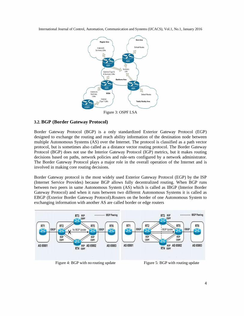
International Journal of Control, Automation, Communication and Systems (IJCACS), Vol.1, No.1, January 2016
4
Figure 3: OSPF LSA
3.2. BGP (Border Gateway Protocol)
Border Gateway Protocol (BGP) is a only standardized Exterior Gateway Protocol (EGP)
designed to exchange the routing and reach ability information of the destination node between
multiple Autonomous Systems (AS) over the Internet. The protocol is classified as a path vector protocol, but is sometimes also called as a distance vector routing protocol. The Border Gateway
Protocol (BGP) does not use the Interior Gateway Protocol (IGP) metrics, but it makes routing
decisions based on paths, network policies and rule-sets configured by a network administrator. The Border Gateway Protocol plays a major role in the overall operation of the Internet and is
involved in making core routing decisions.
Border Gateway protocol is the most widely used Exterior Gateway Protocol (EGP) by the ISP
(Internet Service Provides) because BGP allows fully decentralized routing. When BGP runs
between two peers in same Autonomous System (AS) which is called as IBGP (Interior Border Gateway Protocol) and when it runs between two different Autonomous Systems it is called as
EBGP (Exterior Border Gateway Protocol).Routers on the border of one Autonomous System to
exchanging information with another AS are called border or edge routers
Figure 4: BGP with no routing update Figure 5: BGP with routing update

International Journal of Control, Automation, Communication and Systems (IJCACS), Vol.1, No.1, January 2016
5
3.2.1 Operations of BGP
The neighbors of BGP are called as peers. Among all the routing protocols, BGP is uniquely uses
TCP as their transport protocol on port 179. For every 30 seconds BGP speakers send 19bytes of
keep-alive messages to maintain the connection. BGP which runs between two peers in same autonomous system are called as iBGP (Interior Border Gateway Protocol) and BGP which runs
in inter autonomous system are called as eBGP (Exterior Border Gateway Protocol). A router on
the boundary of different autonomous systems was share the information between each other was called edge router shown in Figure 6.
Figure 6: iBGP and eBGP
4. Wide Area Network using OSPF and BGP Protocols
Implemented in WAN (Wide Area Network) and also implemented in Inter Autonomous System Routing protocols like,
• OSPF(Open Shortest Path First)
• BGP (Border Gateway Protocol)
We have to modify all the metrics of the routing protocol using IPv4 technique.
By implementing the OSPF protocol within the Autonomous System (AS) or WAN (Wide Area
Network) and modifying the metrics of OSPF (Open Shortest Path First) protocol such as. Cost,
reliability, bandwidth and delay we can obtain the optimal performance in the Internal WAN.
We can use BGP (Border Gateway Protocol) for connect more than one Autonomous System
(AS) and make communication among the network (Wide Area Network). By analyzing the
internal and external WAN we can find out the optimal performance of both internal and external Wide Area Network.
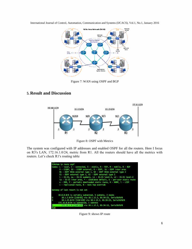
International Journal of Control, Automation, Communication and Systems (IJCACS), Vol.1, No.1, January 2016
6
Figure 7: WAN using OSPF and BGP
5. Result and Discussion
Figure 8: OSPF with Metrics
The system was configured with IP addresses and enabled OSPF for all the routers. Here I focus
on R3′s LAN, 172.16.1.0/24, metric from R1. All the routers should have all the metrics with routers. Let’s check R1′s routing table
Figure 9: shows IP route

International Journal of Control, Automation, Communication and Systems (IJCACS), Vol.1, No.1, January 2016
7
Now, R1′s routing table is showing that the cost for get 172.16.1.0/24 network is 129. Let’s see
how OSPF got the cost of 129. The interface from R1 to R2 is T1 link and the interface from R2 to R3 is T1. Each T1 link has a cost of 64, so now we have two T1 links which make the cost as
128 plus the loopback interface cost, which is 172.16.1.0/24 Loopback interface has a cost of 1
(128+1=129), and see the cost on R3.
Figure 10: Shows Loopback interface
Let’s change R3′s serial 0/1 cost from 64 to 100 then check R1′s routing table for the network
172.16.1.0/24 if the metric value has been changed or not.
Figure 11: Assigning cost
Figure 12: OSPF after assigning cost
After changing R3′s interface serial0/1 cost to 100, R1 still sees the metric as 129 for the network
172.16.1.0/24. Nothing has been changed in R1. Let’s check R1′s routing table for changes after
R2′s serial0/1 cost from 64 to 100.
Figure 13: Assigning cost for Interface SE0/1
Figure 14: Show OSPF route
The metric went up from 129 to 165. Now, we have to know which OSPF uses to calculate the metric.

International Journal of Control, Automation, Communication and Systems (IJCACS), Vol.1, No.1, January 2016
8
In summary, OSPF doesn't use the sending interface cost to calculate route metric, and we tested
that by changing R3′s serial0/1 interface cost to 100. OSPF calculates the cost by using the receiving interfaces of the router in the network. Router R2 was calculated the metric by their
serial0/1 cost (100) plus the neighbor’s cost for all the routes then R2 will advertise those routes
to its neighbors.
6. Conclusion
The main objective of the system focused on choosing the exact hardware requirements
like(Routers, switches and Cables) for creating a different types of wide Area Network
architecture by using the Open Shortest Path First and Border Gateway Protocol for creating inter-autonomous system and intra-autonomous system. We can obtain the optimal performance of the
Internal and External WAN (Wide Area Network) by manipulating the metrics of the BGP
(Border Gateway Protocol) and Open Shortest Path First (OSPF) such as cost, delay, throughput and bandwidth. We can also ensure the QoS (Quality of Service) of the networks.
References
[1] Neha Grang and Anuj Gupta, “Compare OSPF Routing Protocol with other Interior Gateway Routing
Protocols”, IJEBEA 13-147, Vol 1, pp.2-4, 2013
[2] Nikhil Hemant Bhagat,” Border Gateway Protocol –A Best Performance Protocol When Used For
External Routing than Internal Routing”, Vol 1, pp.1-2, 2012
[3] Mohammad Nazrul Islam and Md. Ahsan Ullah Ashique, “Simulation Based EIGRP over OSPF”, Vol 1,pp.4-5, 2010
[4] Christopher Carothers, Murat Yuksel, David Bauer and Shivkumar Kalyanaraman , “A Case Study in
Understanding OSPF and BGP Interactions Using Efficient Experiment Design”, Vol 1,pp.2-4, 2006 [5] Toni Farley, Patrick Mcdaniel and Kevin Butlera, “Survey of BGP Security Issues and
Solutions”,AT&T Labs Research, ACM Journal, Vol. V, Month 20YY
[6] Craig Labovitz, Farnam Jahanian and G. Robert Malan “Internet Routing Instability”, IEEE/ACM
Transactions on Networking, vol. 6, October ,pp.2-3, 1998
[7] Tony Larsson, Nicklas Hedman and Per Johansson, “Scenario-based Performance Analysis of
Routing”,Volume1,pp.3-4
[8] Toshihiko Kato,“Analysis of Internet Multicast Traffic Performance Considering Multicast Routing
Protocol”,Vol 1,pp.2-3 [9] http://en.wikipedia.org/wiki/Border_Gateway_Protocol [10] http://features.techworld.com/networking/600/bgp-metrics/ [11] http://www.cisco.com/en/US/tech/tk365/technologies_tech_note09186a0080094431.shtml
[12] http://networkshinobi.wordpress.com/2011/11/19/ospf-metric-calculation-but-which-interface-does- it-
use-to-calculate-its-metric/ [13] http://www.cisco.com/en/US/tech/tk365/tk480/tsd_technology_support_sub-protocol_home.html [14] http://en.wikipedia.org/wiki/Link-state_advertisement
[15] http://en.wikipedia.org/wiki/Open_Shortest_Path_First

BGP routing policies in ISP networks
Matthew Caesar
UC Berkeley
Jennifer Rexford
Princeton University
Abstract
The Internet has quickly evolved into a vast global network
owned and operated by thousands of different administra-
tive entities. During this time, it became apparent that vanilla
shortest-path routing would be insufficient to handle the myriad
operational, economic, and political factors involved in routing.
ISPs began to modify routing configurations to support routing
policies, i.e. goals held by the router’s owner that controlled
which routes were chosen and which routes were propagated
to neighbors. BGP, originally a simple path-vector protocol,
was incrementally modified over time with a number of mecha-
nisms to support policies, adding substantially to the complex-
ity. Much of the mystery in BGP comes not only from the pro-
tocol complexity but also from a lack of understanding of the
underlying policies and the problems ISPs face which they ad-
dress. In this paper we shed light on goals operators have and
their resulting routing policies, why BGP evolved the way it
did, and how common policies are implemented using BGP.
We also discuss recent and current work in the field that aims
to address problems that arise in applying and supporting rout-
ing policies.
1 Introduction
In the early days of the Internet, the problem of how to route
packets to their final destination was much simpler than it is
today. At the time, the requirements of the Internet’s rout-
ing protocol were fairly simple, as the Internet was small
by today’s standards, operated by a single administrative en-
tity (NSFNET), and shortest-path routing was typically used.
Over time, as the Internet became more heavily commercial-
ized and privatized, Internet Service Providers (ISPs) began to
have vested interests in controlling the way traffic flowed for
economic and political reasons. The Border Gateway Protocol
(BGP) was born out of the need for ISPs to control route selec-
tion (where to forward packets) and propagation (who to export
routes to).
When BGP was first introduced, it was a fairly simple path-
vector protocol. Over time, many incremental modifications to
allow ISPs to control routing were proposed and added to BGP.
The end result was a protocol weighted down with a huge num-
ber of mechanisms that can overlap and conflict in various un-
predictable ways. These modifications can be highly mysteri-
ous since many of them, including the decision process used
to select routes, are not part of the protocol specification [1].
Moreover, their complexity gives rise to several key problems,
including unforeseen security vulnerabilities, widespread mis-
configuration, and conflicts between policies at different ISPs.
Addressing BGP’s problems is difficult, as changing certain as-
pects of BGP (for example changing the contents of update
messages or the way they are propagated) must be coordinated
and simultaneously implemented in other ISPs to support the
new design. Hence most modifications to the protocol have
been made to the decision process BGP uses to choose routes.
The result is a protocol where most of the complexity is in the
decision process and the policies used to influence decisions,
while the rest of the protocol remained fairly simple over time.
Therefore, in order to understand BGP it is necessary to under-
stand this decision process and the policies of ISPs that gave
rise to its design. Understanding policies is also key to solving
BGP’s problems, understanding measurement data from BGP,
or determining what features to support when developing a new
version of BGP.
The range of policies used by operators constitutes a huge space
and hence it is impossible to list them all here. Instead, we try to
list common goals of network operators and the knobs of BGP
that can be used to express policies. In particular, we attempt
to isolate certain design patterns commonly used by ISPs, the
motivations behind them, and how they are implemented in an
ISP’s network using BGP’s mechanisms. We taxonomize poli-
cies into four general categories: business relationship policy
(Section 3) arising from economic or political relationships an
ISP has with its neighbor, traffic engineering policy (Section 4)
arising from the need to control traffic flow within an ISP and
across peering links to avoid congestion and provide good ser-
vice quality, policies for scalability (Section 5) to reduce con-
trol traffic and avoid overloading routers, and security-related
policies (Section 6) that are often used to protect an ISP against
malicious or accidental attacks. We also discuss several avenues
of research currently in progress related to BGP policies (Sec-
tion 7). We start by giving an overview of BGP routing in the
next section.
2 BGP routing in a single AS
The Internet consists of thousands of Autonomous Systems
(ASes)—networks that are each owned and operated by a single
institution. BGP is the routing protocol used to exchange reach-
ability information across ASes. Usually each ISP operates one
AS, though some ISPs may operate multiple ASes for business
reasons (e.g. to provide more autonomy to administrators of an
ISP’s backbones in the United States and Europe) or historical
reasons (e.g. a recent merger of two ISPs). Non-ISP businesses
(enterprises) may also operate their own ASes so as to gain the
additional routing flexibility that arises from participating in the
BGP protocol.
Compared to enterprise networks, ISPs usually have more com-
plex policies arising from the fact that they often have several
downstream customers, connect to certain customers in mul-
tiple geographic locations, have complex traffic engineering
goals, and run BGP on internal routers (rather than just border

routers as enterprises often do). Although some of the observa-
tions we make apply to enterprise networks, our core focus in
this paper is on ISP networks. In this section, we describe BGP
from the standpoint of a single AS, describing first the protocol
that transmits routes from one AS to another, then the decision
process used to choose routes, and finally the mechanisms used
at routers to implement policy.
2.1 Exchanging routing state
Figure 1: Example topology with three ISPs A, B, and C.
Figure 1 shows a simple BGP network. BGP sessions are es-
tablished between border routers that reside at the edges of
an AS and border routers in neighboring ASes. These sessions
are used to exchange routes between neighboring ASes. Border
routers then distribute routes learned on these sessions to non-
border (internal) routers as well as other border routers in the
same AS using internal-BGP (iBGP). In addition, the routers
in an AS usually run an Interior Gateway Protocol (IGP) to
learn the internal network topology and compute paths from
one router to another. Each router combines the BGP and IGP
information to construct a forwarding table that maps each des-
tination prefix to one or more outgoing links along shortest
paths through the network to the chosen borderrouter.
BGP is a relatively simple protocol with a few salient features.
First, BGP is an incremental protocol, where after a complete
routing table is exchanged between neighbors, only changes to
that information are exchanged. These changes may be new
route advertisements, route withdrawals, or changes to route
attributes. Second, BGP is a path-vector protocol where ad-
vertisements contain a list of ASes used to reach the destina-
tion. Third, routes are advertised at the prefix level, so an AS
would send a separate update for each of its reachable prefixes.
Fourth, BGP update messages may contain several fields, in-
cluding a list of prefixes being advertised, a list of prefixes be-
ing withdrawn, and a list of route attributes that describe vari-
ous characteristics of each advertised route. An ISP implements
its policies by modifying route attributes and changing the way
routers react to advertisements with certain route attributes, as
discussed below.
2.2 Selecting a route at a router
A BGP router in an ISP may have several alternate routes to
reach a particular destination. In the absence of policy, the
router would choose the route with the minimum pathlength,
with some arbitrary way to break ties between routes with the
same pathlength. However, in order to give operators greater
Table 1: Steps in the BGP decision process.
Step Attribute Controlled by local
or neighbor AS?
1. Highest LocalPref local
2. Lowest AS path length neighbor
3. Lowest origin type neither
4. Lowest MED neighbor
5. eBGP-learned over iBGP-learned neither
6. Lowest IGP cost to border router local
7. Lowest router ID (to break ties) neither
control over route selection, several additional attributes were
added to advertisements, allowing a router to alter its decisions
based on the values of these attributes. The end result is the
BGP decision process, consisting of an ordered list of attributes
across which routes are compared, as shown in Table 1. The
router goes down the list, comparing each attribute in the list
across the two routes. If the routes have different values for the
attribute, the router chooses the one that has the more desirable
attribute, otherwise it moves on to compare the next attribute
in the list. The route that is chosen is used by the router to for-
ward packets. The ordering of attributes allows the operator to
influence various stages of the decision process. For example,
the Local Preference (LocalPref) is the first step in the deci-
sion process. By changing LocalPref, an operator can force a
route with a longer AS path to be chosen over a shorter one. As
another example, the Multi-Exit Discriminator (MED) is typi-
cally used by two ASes connected by multiple links to indicate
which peering link should be used to reach the AS advertising
the attribute. MED was placed lower in the decision process
as this allows an ISP to override these suggestions, e.g. by set-
ting LocalPref. Using a strict ordering of attributes in the de-
cision process simplifies policy expression and makes it easier
to predict the outcome of making configuration changes. While
some vendors allow operators to disable certain steps in the de-
cision process, they typically do not permit the operators to put
the steps in a different order. Hence some policies that violate
this ordering (e.g. ignore AS path length, or first choose lowest
MED then highest LocalPref) may require various hacks which
can complicate router configuration and lead to unforeseen side
effects.
There are different locations where a route attribute can be set
by policy: (a) Locally, for example LocalPref is an integer value
set at and propagated throughout the local AS and filtered be-
fore sending to neighboring ISPs. (b) Neighbor, for example
the MED attribute is typically used by two ASes connected by
multiple links to indicate which peering link should be used to
reach the AS advertising the MED attribute, and is not used
to compare routes through two different next-hop ASes. (c)
Neither: some attributes, for example whether the route was
learned through an external BGP (eBGP) neighbor or from an
internal router speaking BGP (iBGP), are set by the protocol
and cannot be changed.
The collective results of the decision process across routers is
to produce a set of equally good border routers for each pre-
fix, where each router in the set is equivalent according to the

first four steps of the decision process that compare BGP at-
tributes. Each internal router then chooses the router in that
set that is closest according to the Interior Gateway Protocol
(IGP) path cost to reach that border router. For example in Fig-
ure 1, suppose prefix 6.0.1.0/24 is reachable to B via both A
and C, but B’s LocalPref is set higher for routes through A. The
set of equally good border routers would then contain R1 and R2, and each router in B would select the route that was clos- est exit point (lowest IGP cost): ra and R1 would choose the route through R1, and all other routers would choose the route through R2.
There are three steps a router uses to process route advertise-
ments. First import policy is applied to determine which routes
should be filtered and hence eliminated from consideration, and
may append or modify attributes. Next, the router applies the
decision process to select the most desirable route. Finally, an
export policy is applied which determines which neighbors the
chosen route will be exported to. An ISP may implement its
policy by controlling any of these three steps, i.e., by modify-
ing import policy to filter routes it doesn’t want to use, modi-
fying route attributes to prefer some routes over others, or by
modifying export policy to avoid providing routes for certain
neighbors to use. In addition, an ISP can modify attributes of
routes it advertises, which can influence how its neighbors per-
form route selection.
2.3 Configuring local policies
There are three classes of “knobs” that can be used to control
import and export policies:
1. Preference influences which BGP route will be chosen for
each destination prefix. Changing preference is done by
adding/deleting/modifying route attributes in BGP adver-
tisements. Table 1 shows which attributes can be modified
during import to control preference locally, and which can
be modified during export to change how much a neighbor
prefers the route.
2. Filtering eliminates certain routes from consideration and
also controls who they will be exported to. Filtering may
be applied both before preference (inbound filtering) or
after preference (outbound filtering). Filtering is done by
instructing routers to ignore advertisements with attributes
matching certain specified values or ranges.
3. Tagging allows an operator to associate additional state
with a route, which can be used to coordinate decisions
made by a group of routers in an AS, or to share context
across AS boundaries. The key mechanism is the com-
munity attribute [2] [3], a variable-length string used to
tag routes. The community attribute is a highly expres-
sive mechanism, lending itself to support a wide variety
of complex policies that are difficult to express through
other means. For example, one community value might
affect how the receiving router sets LocalPref, while an-
other might cause the route to be filtered at another router.
However, its expressiveness gives potential for misconfig-
uration, which is exacerbated by the fact that community
attributes usage is not standardized.
An ISP implements its policies by applying configuration com-
mands at routers. These configurations typically consist of a set
of lists of preference, filtering, and tagging rules, one list for
each session the router has with a neighboring BGP-speaking
router. Although the configuration language differs between
vendors, a key primitive that is often provided is a route-map,
a language construct used to modify route attributes and define
conditions that determine which routes are exported to peers.
It consists of two parts: a set of conditions indicating when the
map is to be invoked (e.g. the prefix is a specified value, or the
AS path matches a specified regular expression), and the action
to be taken if the advertisement matches the conditions (e.g.
modify a specified attribute, or filter the route).
3 Business relationships
ISPs often wish to control next hop selection so as to reflect
agreements or relationships they have with their neighbors.
Three common relationships ISPs have are: customer-provider,
where one ISP pays another to forward its traffic, peer-peer,
where two ISPs agree that connecting directly to each other
(typically without exchanging payment) would mutually bene-
fit both, perhaps because roughly equal amounts of traffic flow
between their networks, and backup relationships, where two
ISPs set up a link between them that is to be used only in the
event that the primary routes become unavailable due to failure.
There are two key ways these relationships manifest themselves
in policy:
Influencing the decision process (by assigning LocalPrefs):
ISPs often prefer customer-learned routes over routes learned
from peers and providers when both are available. This is often
done because sending traffic through customers generates rev-
enue for the ISP while sending traffic through providers costs
the ISP money and sending to peers can skew the balance of
power in the peering relationship and thereby give incentive to
the party receiving more traffic to tear down the relationship or
start charging the other party. Often an ISP will achieve this by
assigning a non-overlapping range of LocalPref values to each
type of peering relationship; for example LocalPref values in
the range 90-99 might be used for customers, 80-89 for peers,
70-79 for providers, and 60-69 for backup links. LocalPref can
then be varied within each range to do traffic engineering with-
out violating the constraints associated with the business re-
lationship, as described in Section 4. As another example, a
large ISP spanning both North America and Europe may wish
to avoid forwarding traffic generated by its customers across an
expensive transatlantic link. This can be done by configuring
its European routers with a higher LocalPref for routes learned
from European ISPs, and giving its North American routers a
lower LocalPref for these routes.
Controlling route export (by using the community at-
tribute): Routes learned from providers or peers are usually not
exported to other providers or peers, because there is no eco-
nomic incentive for an ISP to forward traffic it receives from
one provider or peer to another. This can be done by tagging
advertisements with a community attribute signifying the busi-
ness relationship of the session, and filtering routes with certain
community attributes when exporting routes to peers. For ex-
ample, suppose B wishes to not export routes learned from A

to C (Figure 1), perhaps because it does not get paid for transit-
ting traffic from C to A. It can do this as follows. First, for every
session routers R1 and R2 have with routers in A, B configures
an import policy that appends the community attribute Xpeer to
any route learned over these sessions, to indicate that the route
was received from a peer—information which is ordinarily lost
in BGP as the route propagates across the AS. After appending
the community attribute, B exports the route onwards into its
internal iBGP network. Second, B configures export policies at
R4 that match on this community attribute to determine which
routes get exported to C. In particular, every session between
R4 and a router in C is configured with an export policy that
filters any route with the community attribute Xpeer.
4 Traffic engineering
While business relationships affect relative preferences for
routes, there are often several routes available that are equally
preferred. Moreover, ISPs often connect at multiple locations to
reduce delay and improve reliability, increasing the number of
available routes. A secondary goal for many ISPs is to engineer
their traffic by modifying preference within the same business
class to meet or maximize certain performance criteria (e.g.,
achieve desired quality and availability). An ISP can do this by
modifying the import policies applied by its routers, each of
which can have a different configuration. In this section we de-
scribe several common traffic engineering goals (a related topic,
ensuring the selected routes are stable, is discussed in[4]).
Outbound traffic control (by changing LocalPref and IGP
costs): Operators can influence outbound traffic flow either by
configuring import policies that affect which routes get in the
set of equally-good border routers, or by modifying IGP link
costs. One common goal is early-exit routing (also called hot-
potato routing), where the ISP forwards traffic to its closest pos-
sible exit point, so as to reduce the number of links packets tra-
verse and hence the resulting congestion in its internal network.
Although early-exit routing is known to inflate end-to-end path
lengths in the Internet, ISPs often exercise early-exit routing to
reduce their costs and network congestion, and because BGP
does not support alternatives like determining global shortest
paths across multiple ISPs.
Another common goal is to reduce congestion on outbound
links to neighbors. This can be done by load balancing traffic
over several links when possible. Outbound traffic engineering
can be done by changing LocalPref. For example, suppose B
wishes to shift some traffic from its links to A to its link to C as
shown in Figure 1, perhaps because the link to A is overutilized
or because it is planning to take the link down for maintenance.
B can reduce the traffic it sends to A and increase traffic it sends
to C by decreasing LocalPref for routes traversing A or increas-
ing LocalPref for routes traversing C.
Achieving a specific level of load balance (e.g. balancing load
to make spare capacity on both links equal) can be very dif-
ficult. The key challenge is to select the proper set of prefixes
and change attributes for each appropriately; selecting too large
a set will cause too much traffic to shift, overloading one of the
links. It can also be tedious to express a long list of prefixes in
a router configuration file. Some ISPs deal with this by chang-
ing preference for all prefixes whose AS path matches a regu-
lar expression, then tweaking the regular expression repeatedly
to control how many prefixes match it. However, since this is
done manually it is subject to misconfiguration, cannot be done
in real time to adjust to changing load, and the outcome from
a change can be difficult to predict. There are automated tools
that an ISP can use to predict the effects of these actions [5].
Inbound traffic control (by AS prepending and MED): An
ISP’s internal congestion may be exacerbated by its neighbors,
because its neighbors might not be aware of the ISP’s traffic-
engineering goals, internal topology, or load on internal links
due to privacy reasons. Hence, some mechanism to allow an
ISP to control how much traffic it receives from each of its peer-
ing links is essential. Unfortunately, this is a highly challenging
problem, as it requires the local ISP to influence route selection
in remote ISPs, which in turn might wish to limit or completely
ignore the local ISP’s goals. However, an ISP may convince
its neighbor (perhaps through economic incentives) to allow
the ISP to control how much traffic it receives on each link
from the neighbor. This can be done by modifying the MED
attribute, which can be used between a pair of ISPs connected
via multiple peering links. For example, if B wanted to reduce the amount of traffic traversing router R1, it could increase the value of the MED attribute R1 advertises to A, causing the link to R2 to become more preferred by A’s routers and thereby de- creasing R1’s load.
Shifting traffic between links to different neighbors is more
challenging, as unfortunately BGP was not designed with a
mechanism to control route selection in ASes multiple hops
away. However, a workaround commonly used is for an AS to
prepend multiple copies of its AS number to the AS path in or-
der to artificially inflate the AS-path length. For example, sup-
pose B wishes to shift some traffic from its link to A to its link
to C. B can do this by prepending additional copies of its AS
number onto the AS paths in BGP advertisements it sends to
A. This increases the AS-path length in these advertisements,
which causes routes advertised by C to other ISPs to become
more desirable in comparison.
Remote control (by changing community attributes): In cer-
tain cases, an ISP may need to remotely manage a router’s
configuration to implement a desired policy. For example in
Figure 1, suppose B wishes to have all inbound traffic routed
through A, and suppose C peers with A (not shown in the fig-
ure). If C has a LocalPref to prefer the direct route to B, no
change in MED or AS prepending will force C to use alter-
nate routes through A to B. B could request C to manually
change its router configurations, but this can be time consum-
ing for human operators if B changes its policy often (e.g. for
traffic engineering purposes). Instead, C can allow B to control
C’s routing policy with respect to B’s routes by configuring its
routers to map certain community attributes to certain Local-
Pref values [2]. If desired, C can limit the degree of B’s control
to prevent certain policies of its own from being subverted. For
example, C can configure its routers to map community value
X1 to a LocalPref of 60, and X2to a LocalPref of 75, allowing
B to disable the route, but not allowing B to have it chosen over
routes C wants to prefer more (by setting a higher LocalPref,
like 85).
Remote control has some overlapping functionality with other

mechanisms to control inbound and outbound traffic. In gen-
eral, remote control is typically used to allow a customer to tell
its provider to perform some action on its behalf. Remote con-
trol provides more flexibility than MED because it allows con-
trol of inputs to earlier steps of the decision process like Local-
Pref, as shown in the example above. Moreover, MED can only
change the relative preference of routes, while remote control
can be configured to filter routes, or perform AS prepending.
Further, MED is only used for routes with the same next-hop
AS, while LocalPref is compared across routes learned from
all neighbors. However, as with MED, an ISP’s neighbors must
agree in advance to accept community attributes from the other
peer. Also, the highly expressive nature of community attributes
introduces potential for misconfiguration. For example, two ad-
jacent ISPs may use the same community attribute to mean very
different things (e.g., one might use it for accounting purposes
to indicate a certain customer generated the route, while an-
other might use it to indicate the route should be filtered). If a
misconfigured router allows the attribute to be passed between
them without being removed, unintended consequences could
ensue. ISPs typically address this by careful router configura-
tion, and by publishing the list of communities and what actions
they trigger for their customers.
In addition, there are a variety of “smart routing” tools [6] that
small ASes at the edge of the Internet can use to balance out-
bound traffic over multiple upstream providers. However, these
tools generally are not appropriate for ISPs, as dynamically
changing traffic can lead to BGP routing changes that are vis-
ible to other ASes, which can trigger flap damping (a mecha-
nism that withdraws unstable routes) if the routes become too
unstable. Moreover, these tools focus on load balancing over
multiple outgoing links but do not consider the effect on traffic
flow inside the AS [5].
5 Scalability
Some misconfigurations and faults in neighboring ISPs can lead
them to generate excessive rates of updates. Sending updates
too frequently can trigger route instability, leading to poor ser-
vice quality, or can overload a router’s processing capability
or memory capacity, which can cause outages and router fail-
ure. A properly configured set of BGP policies can improve the
resilience of a network to these problems. Common goals in-
clude:
Limiting routing table size (by filtering and using the com-
munity attribute): ISPs often want to limit routing table size
because overflow can cause the router to crash [7]. This can be
a particularly important issue for smaller ISPs which may have
less expensive routers with less memory capacity.
1. Protection from other ISPs: ISPs can protect themselves
from excessive advertisements from neighbors by: (a) Fil-
tering long prefixes (e.g., longer than /24) to encourage
use of aggregation [8]. (b) As a safety check, routers of-
ten maintain a fixed per-session prefix limit that limits the
number of prefixes a neighbor can advertise. (c) Default
routing: an ISP with a small number of routes may not
need the entire routing table, and may instead configure
a default route through which most destinations can be
reached.
2. Protecting other ISPs: An ISP can reduce the number of
prefixes it advertises by using route aggregation, where in-
stead of advertising two adjacent prefixes (e.g., 4.1.2.0/24
and 4.1.3.0/24) to a neighbor, they can be filtered in the ex-
port policy and a less specific prefix (e.g. 4.1.2.0/23) ad-
vertised [9]. However, doing this effectively may require
knowledge of the neighbor’s connectivity (which is not
discovered or signaled by the BGP protocol and hence
must be manually detected and accounted for by human
operators) as illustrated in the following example.
Figure 2: Example topology where adding new customer D trig-
gers E to generate (a) no new advertisements (b) internal adver-
tisement (c) internal and external advertisements.
Suppose E (Figure 2) owns prefix 6.0.0.0/8. E has allocated the subnet 6.1.0.0/16 to router R5, and has allocated smaller sub- nets to its customers connected to R5, including a new cus- tomer D which is allocated subnet 6.1.1.0/24. When adding D
as a new customer, E may need to make changes to its routers’
configuration, and the configuration it chooses impacts whether
new advertisements are generated. There are threecases:
1. No new advertisements: Suppose D’s sole provider is E,
and D connects to just one router R5 in E. In this case, R5 is already advertising 6.1.0.0/16 within AS E, obviat- ing the need for R5 to advertise more specific subnets like 6.1.1.0/24. Hence, E just adds a statically configured route at R5 to forward all traffic in 6.1.1.0/24 to D, and so no advertisements will be sent from E to its neighbors, nor will any new advertisements be sent internally within E.
2. Internal advertisement: Suppose instead D connects to two routers R5 and R6 in E. In this case, both R5 and R6
need to advertise the prefix 6.1.1.0/24 within E, so all
routers within E know they can reach D via either R5 or R6. However, E can aggregate the advertisement into its address space and hence E will not send BGP advertise- ments for 6.1.0.0/24 to its neighbors. This is done by con-
figuring R5 and R6 to tag a community attribute onto ad- vertisements of prefix 6.1.1.0/24, and configuring all bor- der routers to filter routes with that community attribute.
3. External and internal advertisement: Suppose D connects
to both E and F. In this case E should not aggregate the
prefix into its own address space; if it did, then F would
then be advertising a longer prefix route to reach D, and
since routers forward packets based on the longest pre-
fix match, all routers in the Internet will prefer F’s route

over E’s route. If D wishes traffic to flow over both links,
it must request that E not perform aggregation on its pre-
fix. E can avoid aggregating the prefix by configuring its
routers peering with D to append a certain community at-
tribute, and configure its border routers to export routes
containing that community attribute.
Limit the number of routing changes (by suppressing routes
that flap): Routing instability is undesirable, as it can increase
CPU load on routers, which can increase reaction time to im-
portant events. Also, frequent shifting of traffic to different
paths can introduce jitter and packet loss in applications like
Voice-over-IP and interfere with TCP’s round-trip-time calcu-
lations. The key mechanism used to improve routing stability
is flap damping. Flap damping is a mechanism that limits prop-
agation of unstable routes. It works by maintaining a penalty
value associated with the route that is incremented whenever
an update is received. When the penalty value surpasses a con-
figurable threshold, the route is suppressed for some time, i.e.,
it is made unavailable to the decision process and hence will not
be selected. An ISP can lower the penalty threshold to improve
route stability at the cost of worsening availability. ISPs may
wish to less aggressively dampen or disable damping for certain
prefixes, for example routes to the root Domain Name System
servers, or routes from customers with high availability require-
ments. Also, ISPs sometimes more aggressively dampen longer
prefixes than shorter prefixes, with the motivation that damp-
ing a shorter prefix can have a large effect on reachability [10].
This can be done by configuring a route-map that matches on
the prefix length or a specific prefix and sets the flap damping
parameters accordingly.
6 Security
An AS is highly vulnerable to false information in BGP up-
dates. By sending false information, an ISP can subvert a neigh-
bor’s routing goals, cause routers to overload and fail, or de-
grade service quality. False information can have a significant
influence on routing in an AS, even if the source of the informa-
tion is several AS hops away [11]. Such information is some-
times generated by router bugs and misconfiguration. It could
also be maliciously generated by an ISP’s neighbor, who may
be competing for customers and hence has a vested interest in
making the ISP’s customers dissatisfied with service. Hence an
ISP may wish to exercise defensive programming to protect it-
self against attacks.
Discarding invalid routes (by import filtering): ISPs may
wish to protect their customers from learning invalid routes
by performing sanity checks to ensure update contents are
valid before propagating them internally. For example, routes
to special-use or private addresses, or address blocks that have
not yet been allocated are obviously invalid [12]. Moreover,
advertisements from customers for prefixes they do not own
should not be propagated. ISPs can also perform certain sanity
checks on the AS path; for example a Tier-1 ISP should not ac-
cept any routes from its customers that contain another Tier-1
ISP in the AS path. Also, advertisements containing private AS
numbers in the AS path may be considered invalid. ISPs may
configure its filters based on the contents of public repositories
of routing configurations called routing registries, other public
reports [13], or private disclosures from neighbors.
Protect integrity of routing policies (by rewriting at-
tributes): An ISP may want to prevent a neighboring AS from
having undue influence over its routing decisions, in violation
of their peering agreement. Otherwise, the ISP could be duped
into carrying traffic a longer distance across its backbone on
the neighbor’s behalf. For example, suppose the ISP peers with
a neighbor in both New York and San Francisco. By advertis-
ing a prefix with a MED of 0 in New York and a MED of 1
in San Francisco, the peer could trick the ISP into having all
of its routers direct traffic for this destination through the New
York peering point, even if the San Francisco peering point is
closer. The peer could achieve the same goal by configuring
its San Francisco router to advertise the route with the next-
hop attribute wrongly set to the IP address of the New York
router. To defend against violations of peering agreements, the
ISP can configure the import policy to delete attributes or over-
write them with the expected values. For example, the import
policy could set all MED values to 0, unless the ISP has agreed
in advance to honor the neighbor’s MEDs. Similarly, the im-
port policy could set the next-hop attribute to the IP address
of the remote end of the BGP session, and remove any unex-
pected community values. Unfortunately, these techniques are
not sufficient to prevent all violations of peering agreements1.
Securing the network infrastructure (by export filtering):
An ISP may wish to prevent external entities from accessing
certain internal resources by configuring its export policies that
filter BGP advertisements for destinations that should not be
externally reachable. For example, the ISP may protect its own
backbone infrastructure by filtering the IP addresses used to
number the router interfaces. The ISP may also wish to pro-
tect certain key internal services, by filtering the addresses of
the hosts running network-management software. Finally, as a
courtesy to its neighbors, an ISP may also do export filtering of
invalid routes (e.g., routes with invalid addresses or contents),
as a preventative measure.
Blocking denial-of-service attacks (by filtering and damp-
ing): Denial-of-service attacks can degrade service by over-
loading the routers with extra BGP update messages or con-
suming excessive amounts of link bandwidth. For example, the
ISP’s routers could run out of memory if a neighbor sends route
advertisements for a large number of destination prefixes. To
protect itself, the ISP can configure each BGP session with a
maximum acceptable number of prefixes, tearing down the ses-
sion when the limit is exceeded; in addition, the import pol-
icy could filter prefixes with large mask lengths (e.g., longer
than /24). As another example, a neighbor sending an exces-
sive number of BGP update messages can easily deplete the
CPU resources on the ISP’s routers. Upon detecting the exces-
sive BGP updates, the operators could modify the import pol-
icy to discard advertisements for the offending prefixes or dis-
able the BGP session. Upon identifying the neighbor or prefix
1For example, many peering contracts require a peer to announce a
prefix at all peering points, with AS paths of the same length [14, 15].
An ISP can detect this kind of inconsistency by comparing the BGP ad-
vertisements across all peering points [16] or collecting detailed mea-
surements of the traffic traversing the peering links.

responsible for the excessive BGP updates, the ISP can more
aggressively dampen (Section 5) or even completely filter up-
dates it receives from these sources. In addition to BGP’s own
vulnerabilities to attack, an ISP (or its customers) may be sub-
ject to a denial-of-service attack where excessive data traffic
is sent to victim hosts. An ISP can block the offending traf-
fic by installing a blackhole route that drops traffic destined to
the victim addresses. Blackhole routes may be statically con-
figured, or operators may run a special BGP session that adver-
tises the prefixes of the victims [17]. Routers receiving prefixes
on this session then assign the next-hop to be an address as-
sociated with the “null” route (a route which drops all traffic),
or the address of a monitoring system that can perform further
analysis of the traffic. Using a similar technique, the ISP can
advertise the address blocks of known spammers to blackhole
traffic sent to these addresses. These blackhole routes prevent
the spammers from establishing bidirectional communication
(i.e., a TCP connection, which depends on receiving a SYN-
ACK packet) with the ISP’s mail servers.
7 Looking forward
BGP’s rich feature set of tunable knobs and complex cross-
protocol interactions make it highly subject to a variety of prob-
lems, including misconfiguration, oscillations, and protocol di-
vergence. The challenge of supporting many different complex
policies in BGP without significantly complicating the protocol
or degrading its performance has led to much research activity.
Three key areas of research related to BGP policy are discussed
below (a wider survey of research directions is given in [18]).
Configuration checking: The complexity of Internet routing
makes it difficult to predict the way policies interact, increasing
the prevalence of configuration mistakes. Interdependence of
policy across ISPs and within a single ISP can trigger problems
like persistent route oscillations. Configuration checking tools
can avoid misconfigurations by verifying certain consistency
criteria hold [19], and modeling tools can predict side-effects
of configuration changes on routers within an ISP [5]. Across
ISPs, uncoordinated routing policy can worsen route conver-
gence and stability. The Routing Arbiter [13] project introduced
a distributed architecture for publishing and coordinating rout-
ing policies so as to avoid these problems, but was not widely
deployed. Other work has attempted to coordinate route policy
selection across ISPs without revealing private details of poli-
cies [20].
Language design: Routing Policy Specification Language
(RPSL) [21] is a vendor-neutral language proposed to describe
an ISP’s policy. It was envisioned these descriptions could be
bound together in a database and checked for consistency [13].
RPSL, though mature, is somewhat low-level and mechanism
oriented. It may be possible to substantially improve upon
RPSL by designing router configuration languages with higher
level constructs that allow diverse policies while precluding
certain misconfigurations, enforcing certain consistency prop-
erties to hold, simplifying configuration of certain common de-
sign patterns [22], however the design of such a language re-
mains an open problem.
New architectures: There are several routing architectures
aimed at fixing problems in and extending functionality of BGP.
HLP [23] is a proposed replacement for eBGP. The design phi-
losophy of HLP is to expose common policies that can typically
be inferred in BGP today and optimize the routing protocol
based on the resulting structure, with the aim to improve scal-
ability and convergence of interdomain routes. Routing Con-
trol Platform (RCP) [24] is a logically centralized system that
computes and distributes routes to routers inside an ISP. The
centralization allows policies to be applied at the AS level, and
the RCP applies the policies and its own decision process to se-
lect the best BGP route for each destination prefix on behalf of
each router. This simplifies the configuration and application of
policies and avoids misconfiguration.
8 Conclusion
Although BGP policies can be highly complex, there are a num-
ber of common design patterns that are typically used by ISPs.
In this article we discussed several common patterns and how
they can be realized using BGP policy mechanisms. We believe
that by recognizing these patterns exist we can more efficiently
develop tools that directly support them, such as analysis tools
that check correctness, languages that preclude errors, or archi-
tectures that are designed for common cases.
Acknowledgments: We would like to thank Nick Feamster,
Karthik Lakshminarayanan, Kobus van der Merwe, Fang Yu,
Gautam Altekar, and Dilip Joseph for reading earlier drafts and
providing invaluable feedback.
References
[1] Y. Rekhter, T. Li, “A border gateway protocol 4,” IETF RFC 1771, March 1995.
[2] E. Chen, T. Bates, “An application of the BGP community at- tribute,” IETF RFC 1998, August 1996.
[3] B. Quoitin, O. Bonaventure, “A survey of the utilization of the BGP community attribute,” expired Internet Draft draft-quoitin- bgp-comm-survey-00.txt, February 2002.
[4] Y. Yang, H. Xie, H. Wang, A. Silberschatz, Y. Liu, L. Li, A. Krishnamurthy, “On route selection for interdomain traffic engi- neering,” IEEE Network Magazine, Special issue on Interdomain Routing, Nov-Dec 2005.
[5] N. Feamster, J. Winick, J. Rexford, “A model of BGP routing for network engineering,” in Proc. ACM SIGMETRICS, June 2004.
[6] J. Bartlett, “Optimizing multi-homed connections,” in Business Communications Review, vol. 32, no. 1, pgs. 22-27, January 2002.
[7] D. Chang, R. Govindan, J. Heidemann, “An empirical study of router response to large BGP routing table load” in Proc. Internet Measurement Workshop, November 2002.
[8] S. Bellovin, R. Bush, T. Griffin, J. Rexford, “Slowing routing ta- ble growth by filtering based on address allocation policies,” un- published, June 2001, http://www.cs.princeton.edu/ ˜jrex/papers/filter.pdf
[9] E. Chen, J. Stewart, “A framework for inter-domain route aggre- gation,” IETF RFC 2519, February 1999.
[10] “RIPE routing-WG recommendations for coordinated flap damp- ing parameters,” October 2001, http://www.ripe.net/ ripe/docs/routeflap-damping.html
[11] O. Nordstrom, C. Dovrolis, “Beware of BGP attacks,” in ACM SIGCOMM Computer Communications Review, April 2004.
[12] N. Feamster, J. Jung, H. Balakrishnan, “An empirical study of “Bogon” route advertisements,” in ACM SIGCOMM Computer Communications Review, January 2005.
[13] R. Govindan, C. Alaettinoglu, G. Eddy, D. Kessens, S. Kumar, W. Lee, “An Architecture for Stable, Analyzable Internet Rout- ing,” IEEE Network Magazine, Jan-Feb 1999.
[14] D. Golding, V. Gill, V. Mehta, “America Online: Settlement-free interconnection policy,” web site, http://www.atdn.net/ settlement_free_int.shtml

[15] UUNET, “MCI policy for settlement-free interconnection,” web site http://global.mci.com/uunet/peering/
[16] N. Feamster, Z. Mao, J. Rexford, “BorderGuard: Detecting cold potatoes from peers,” in Proc. Internet Measurement Conference, October 2004.
[17] D. Turk, “Configuring BGP to block Denial-of-Service attacks,” IETF RFC 3882, September 2004.
[18] M. Yannuzzi, X. Masip-Bruin, O. Bonaventure, “Open issues in interdomain routing: a survey,” IEEE Network Magazine, Special issue on Interdomain Routing, Nov-Dec 2005.
[19] N. Feamster, H. Balakrishnan, “Detecting BGP configuration faults with static analysis,” in Proc. Networked Systems Design and Implementation, May 2005.
[20] R. Mahajan, D. Wetherall, T. Anderson, “Negotiation based rout- ing between neighboring domains,” in Proc. Networked Systems Design and Implementation, May 2005.
[21] A. Alaettinoglu, C. Villamizar, E. Gerich, D. Kessens, D. Meyer, T. Bates, D. Karrenberg, M. Terpstra, “Routing policy specifica- tion language (RPSL),” IETF RFC 2622, June 1999.
[22] T. Griffin, A. Jaggard, V. Ramachandran, “Design principles of policy languages for path vector protocols,” in Proc. ACM SIG- COMM, August 2003.
[23] L. Subramanian, M. Caesar, C. Ee, M. Handley, Z. Mao, S. Shenker, I. Stoica, “HLP: A next-generation interdomain routing protocol,” in Proc. ACM SIGCOMM, August 2005
[24] M. Caesar, D. Caldwell, N. Feamster, J. Rexford, A. Shaikh, J. van der Merwe, “Design and implementation of a routing control platform,” in Proc. Networked Systems Design and Implementa- tion, May 2005.
[25] D. Golding, “Routing policy tutorial,” in NANOG 24, http://www.nanog.org/mtg-0202/ppt/golding/ index.html

RESEARCH PAPER

International Research Journal of Engineering and Technology (IRJET) e-ISSN: 2395-0056
p-ISSN: 2395-0072 Volume: 07 Issue: 04 | Apr 2020 www.irjet.net
© 2020, IRJET | Impact Factor value: 7.34 | ISO 9001:2008 Certified Journal | Page 1798
DESIGNING A HIGH LEVEL CO-ORPOREATE NETWORK INFRASTRUCTURE
WITH MPLS CLOUD
1B. Sarat Sasank , 2G.V. Eswara Rao, 3K.S.D. Kuladeep Kumar, 4V. Balu Veeren, 5B. Shraavan Kummar, 6K. Priyanka
1Student, Department of Computer Science & Engineering, Anil Neerukonda Institute of Technology and Sciences, Vi- sakhapatnam, India
2Assistant professor, Department of Computer Science & Engineering, Anil Neerukonda Institute of Technology and Sciences, Visakhapatnam, India
3,4,5Student, Department of Computer Science & Engineering, Anil Neerukonda Institute of Technology and Sciences, Visakhapatnam, India
------------------------------------------------------------------------------------***-------------------------------------------------------------------------- ABSTRACT
The substandard network design makes organizations prone to many security attacks and can lead to information breach since there are many people around us watching and monitoring every possibility to break into the network. So it becomes indispensable to build a network with highly sophisticated techniques and integrating them congruent to the network design. So, we design a network by implementing the technologies that are considered to be the finest in their respective areas there- by providing security to the network from its base. In this paper, we first discuss the protocols and other leading edges that are incorporated in detail for the network design, further their implementations with perspicuous outputs. This document details about MPLS, the technology created over TDM for reliable telecommunication protection along with how efficiently OSPF, HSRP, VLANs, ACLs, and their implicit functionalities are utilized to achieve the intent.
KEYWORDS
Multi Protocol Label Switching (MPLS), Open Shortest Path First (OSPF), Virtual Local Area Network (VLAN), Wide Area Net- work (WAN), Firs Hop Redundancy Protocol (FHRP), Hot Standby Redundancy Protocol (HSRP), Access Control Lists (ACLs), Network Address Translation (NAT), Time Division Multiplexing (TDM), Border Gateway Protocol (BGP), Link State DataBase (LSDB)
INTRODUCTION
In earlier days of networking there aren’t many risks of security attacks and data thefts since the resources of using internet are very less and capitals are high as a result of which a very few people have the cognizance of using the internet but as a con- sequence of globalization every individual now have the access to the internet and number of people using it has ameliorated drastically. Along with the users, the traffic that is generated has been increasing every day which becomes the major threat in preserving security. Instead of providing the very strict rules and norms for a feeble network it is better to design a well de- fined and robust network. So, the network design plays a fundamental role in providing security for any organization being the cardinal level of limiting illegal access and authorizations to organizations. The recent survey conducted across the globe has shown that more than 80 percent of the security violations and outbreaks are caused within the organization than outside which depicts the importance of strong network design.
The implementation of routing protocols like OSPF provides packet flow to the external networks and also succor in keeping different areas that are connected to the backbone area and summarizations for minimal traffic congestions. The HSRP is used for the subsecond network convergence in case of the first hop failure by providing the backup gateway making the network uptime to the maximum extent. The VLANs are configured for the inner organizational security by restricting the data trans- ferring to particular subnets and allowing it to flow under certain circumstances. The NAT also plays an important role in net- work security and from data breach protection by hiding the private addresses and showcasing the public addresses. The type of traffic flow which is the key factor to be examined for illegal entry of packets into the network is provided by the ACLs. The provision of high bandwidth for productive work is accomplished by using route-maps which is called policy-based routing.

International Research Journal of Engineering and Technology (IRJET) e-ISSN: 2395-0056
p-ISSN: 2395-0072 Volume: 07 Issue: 04 | Apr 2020 www.irjet.net
© 2020, IRJET | Impact Factor value: 7.34 | ISO 9001:2008 Certified Journal | Page 1799
We can be able to provide high security for a network by using all the technologies in the right way and in the right propor- tions.
The MPLS technology is mainly used for the reliable transmissions and also to allow the minimum packet dropouts from the transmissions. Apart from MPLS, we can also use employ Frame Relay (FR) for this task but it is not so often used nowadays and incompetent when compared to the MPLS. The MPLS promises a better bandwidth, speed, scalability, Quality of Service (QOS) and traffic control making it a first choice for selecting among the point to point connections. The MPLS forwards the packets by swapping the labels of incoming and outgoing packets and their ports. This forwarding is based on the labels which are dependent not only on the ip addresses but also on paths, services management, congestion, QoS and other factors which makes it different from the traditional ip forwarding. All the label switch routers (LSR) which are present in the cloud are not of the same kind. Some give priority for the data, some for the voice and some for the video forwarding. This way MPLS makes its selection and switches the packets accordingly.
LITERATURE SURVEY
There are many research works related to the technologies and protocols that are used in the network design. They have pro- vided the structure and usage of particular technology severally in their distinctive works like OSPF, MPLS, BGP, FHRP. One cannot use the best metrics in the particular technology to make a good network design. The selection of the extent to which these technologies to be used is purely and solely depends on the type of network that is designed. One cannot presume or possess a standard network design but has to use the knowledge of them to design the network of their own in the way they require for the organization. This document is about designing a good network using MPLS as a main and effective use of other technologies to build a high-end secure network according to the requirement and congruence with one another that is not susceptible to the attacks.
SYSTEM ARCHITECTURE

International Research Journal of Engineering and Technology (IRJET) e-ISSN: 2395-0056
p-ISSN: 2395-0072 Volume: 07 Issue: 04 | Apr 2020 www.irjet.net
© 2020, IRJET | Impact Factor value: 7.34 | ISO 9001:2008 Certified Journal | Page 1800
METHODOLOGIES
ROUTING PROTOCOL
It is important to learn the routes not only those which are directly connected to a router but also those that are obliquely connected. The former one's information is obtained from the interface particulars and configurations. For the later ones, we need routing protocols to accomplish the task. The routing protocols allow communication between different routers and help them in exchanging their information with the others.
The routing protocols mainly work by the principle of exchanging hello messages. These multicast messages not only help in establishing the relationship between the routers but also in sustaining the relationship even after the connection was estab- lished. The routing protocols are broadly classified into two categories. They are link-state routing protocols and distance- vector routing protocols. The usage of link-state routing protocols is preferred to distance-vector as they contain the complete knowledge on all the routes present in the network whereas the distance-vector just possesses information only about the directly connected routes.
However, the preference is done on the design of the topology.
OSPF
OSPF which stands for Open Shortest Path First is a link-state classless routing protocol that is being widely used in organiza- tions for its many advantages. It maintains a topological table also know as LSDB (Link State DataBase) and uses Dijkstra's shortest path algorithm for its route selection process. It works well on both simple and advanced network topologies that make it feasible for everyone. OSPF unlike RIP uses bandwidth and delay as the metrics for the route selection process and can provide equal load balancing.
In OSPF, forming the neighbor relation follows some sequences of steps. First, the router must be given a router-id manually or else the highest interface ip-address will be considered as its router-id. The interfaces that are connected are to be added to the link-state database and then hello messages are exchanged between the routers. The hello messages must have the same hello and dead timers, areas, subnet mask, authentication passwords for the successful exchange.
Succeeding the hello message transfer, the routers are related and are said to be in a master-slave relationship and form neighbors. This is followed by required information transfer between the routers from their databases which are acknowl- edged and reviewed. Finally, after these steps, the neighbors are synchronized and said to be in FULL STATE.
The presence of too many routers in the topology results in network loop when an update occurs because in the link-state routing the updates are being transmitted to every router that creates a network loop. To control this, a router per ethernet will be selected and is assigned the role of transmitting the route updates thereby controlling the chances of a loop. This se- lected router is known as Designated Router (DR) and a backup for this router is also selected which is called Backup Desig- nated Router (BDR). The DR selection can be done manually by giving more priority or dynamically by selecting the one hav- ing the highest router-id. The DR maintains the 2-way relation with the other routers.
The ospf being a link-local routing protocol contains a large database of routes which sometimes leads to overload and conges- tion within the network. So, in ospf protocol, the network is divided into small groups called areas that are numbered from ‘0’ to facilitate the administration, confinement of routing updates, resource optimization, and traffic control. Area 0 is known as the BACKBONE area and every other area must be connected to the backbone area.

International Research Journal of Engineering and Technology (IRJET) e-ISSN: 2395-0056
p-ISSN: 2395-0072 Volume: 07 Issue: 04 | Apr 2020 www.irjet.net
© 2020, IRJET | Impact Factor value: 7.34 | ISO 9001:2008 Certified Journal | Page 1801
The routers present at the border of two areas are called AREA BORDER ROUTER (ABR) where we can summarize the routes
0 15 30 45 60
OSPF
RIP
IGRP
EIGRP
ROUTER UPDATES
to provide the feature ‘confinement of routing information’. The routers present at the border to two autonomous systems (end of companies ospf) are called AUTONOMOUS SYSTEM BOUNDARY ROUTER (ASBR). Only ABR and ASBR routers are used to summarize the routes but no other router can perform the job in ospf. However, it is known that every area must be con- nected to area 0 but it can be overruled by connecting to other areas (say area x) by using virtual-links. The virtual-links logi- cally connects the area (x) to the area 0 and spoofs that it is physically connected to area 0.
FHRP
FHRP stands for First Hop Redundancy Protocol, works in layer 3 of the OSI model. It is created typically to provide redundan- cy for a gateway that provides the internet to a network. The gateway router is the only way that a network or subnet is con- nected to the internet, the event of failure makes the complete network into isolation.
So when a failover occurs to the active gateway then the redundant gateway must become active and perform the job of gate- way until the original gateway comes back to the line. The routers in the group must possess the same ip address for the re- dundancy operation but since it is not possible to have the same ip in a subnet we keep a virtual ip that is different from their individual ip for this operation. There are 8 types of FHRP of which HSRP, VRRP, GBP are eminent.
HSRP
The Hot Standby Redundancy Protocol (HSRP) is a Cisco proprietary redundancy protocol that is most popularly used among FHRP to achieve maximum percent of network uptime. It was first created in 1994 by Cisco and it was available in two ver- sions having the port number 1985.
The protocol consists of default values in which the priority and decrementing values are 100 and 10 respectively. The virtual MAC address of HSRP has a form of 0000.0C07. AC XX where 0000.0C is the Cisco vendor id, 07.AC is the HSRP id and XX is the standby group number.
The primary gateway or the first hop is regarded as an active gateway and the secondary gateway is considered as standby gateway in the terminology of HSRP. There will be only one gateway that is active and others in the group will be in a standby state. The active and standby states of a router are determined by the priority values that are assigned to them, the highest priority router becomes the active gateway. The active router is the one that is responsible for responding to the network re- quests. The HSRP group shares a single virtual ip and Mac addresses and every router in the group (in particular is active) re- sponds with the same Mac address upon the ARP requests. It is also possible to keep a separate active gateway for separate VLANs.

International Research Journal of Engineering and Technology (IRJET) e-ISSN: 2395-0056
p-ISSN: 2395-0072 Volume: 07 Issue: 04 | Apr 2020 www.irjet.net
© 2020, IRJET | Impact Factor value: 7.34 | ISO 9001:2008 Certified Journal | Page 1802
HSRP uses multicast messages to exchange the hello messages to keep track of the priority and current values of the gateways. It sends hello messages for every 3 seconds and the hold on or dead timer is set to 10 seconds if it crosses 10 seconds without receiving a hello message the active router goes to the standby state by decrementing the priority value of previous active router which will be gained by the standby to become active. Again if the first-hop gets back from failover then the above pro- cess happens automatically making it the active gateway.
VLANs
The main problem with the switches is that they cannot multicast the messages instead of unicasting and broadcasting. It is because switches only break the collision domain but not the broadcast domain as the routers do. In the practical world, it is not appropriate to place routers everywhere as it adds great complexity to the network. So it becomes paramount for a switch to break the broadcast domain so that only a particular group of devices will receive the messages i.e., multicasting.
VLAN stands for Virtual Local Area Network and works at the data-link layer. The VLANs are regarded as broadcast domains that are divided into different logical groups that communicate as if they were directly connected when there are in the same VLAN group. The VLANs works on the principle of tagging, the VLAN ids are assigned to the ports, when the messages or the data passes through the port will be appended by the VLAN id number that the port is assigned to. So, the ports in a switch containing the same VLAN id are considered to be in one broadcast domain. This process achieves the goal of multicasting in switches.
A switch can possess 4094 VLANs that can be used. The VLAN 1 is considered as a default VLAN and in general, it is also re- garded as native VLAN but it's not necessarily the same. The native VLAN-id numbers must be the same for two switches that are connected for the communication to takes place. The network management protocols like CDP, LLDP, VTP, DTP flow through the VLAN 1 for the maintenance of the configurations.
The switch usually contains 2 types of ports which are access and trunk ports. The ports connecting computer and switch are the access ports and two network devices are trunk ports. If a message is to transferred to the same VLAN in the other switch then the connecting link between the two switches must be made trunk as they allow the tagged traffic. The Inter-Switch link which is a Cisco proprietary and IEEE’s 802.1q which is industry standard are the tagging protocols.
It betides in a practical world to communicate not only within a VLAN group but between the VLANs. Since the communication between two VLANs is regarded as the communication between two broadcast domains this process can be accomplished in three ways in which the first facet is using routers (as it breaks broadcast domain), the second facet is to male use of l3 switch- ing and the final facet is ROAS.
ROAS
The ROAS which is known as Router on a Stick is one of the techniques that is deployed for inter VLAN communication. The main aim here is to break the broadcast domain that paves the path for the communication between the VLANs. This process can be performed by allowing different switches containing single VLAN must be connected to the separate routing interfaces but being the router limited to a very little number of interfaces cannot fully accommodate a large number of VLAN groups which requires more routers that in turn increases the complexity of the network.
To mitigate this problem the sub interfaces of the router are the concept that is emerged which logically divides the single router interface into many sub interfaces that succor in the effective utilization of the router interfaces. Each sub interface is given an ip address to that particular VLAN group and the interface between the router and the switch must be made trunk for the flow of tagged traffic. Eventually, the communication betides between the VLANs
ACCESS CONTROL LISTS
The access-lists are the set of rules that are configured in the router which determines whether a packet to pass through the router or not. These access-lists are used to mitigate the network attacks as it restricts most of the illegal traffic and promotes

International Research Journal of Engineering and Technology (IRJET) e-ISSN: 2395-0056
p-ISSN: 2395-0072 Volume: 07 Issue: 04 | Apr 2020 www.irjet.net
© 2020, IRJET | Impact Factor value: 7.34 | ISO 9001:2008 Certified Journal | Page 1803
network security. One can either permit or deny particular traffic by using their ip addresses and port numbers. Besides access control, they also provide services like NAT, QoS, Demand Dail Routing, Policy routing, Route filtering.
Analogous to the entry list carried by the watchman, the access-lists act like the entry list which checks all the incoming and outgoing traffic from the router. The examination or checking the entries in the access-lists betides from top to bottom and stop at the first match. In general, there are two main types of access-lists they are standard ACLs and extended ACLs. The standard access control lists work only on the source ip address and range from 1-99, 1300-1999. The extended access control lists work on both source and destination ip addresses and have a number range from 100-199, 2000-2699.
NAT
The ipv4 being a 32-bit always have a dread for ip completion. The discovery of private ip addresses made this a long-lasting process. The public ip addresses are brought from the ISP and the ones that are being advertised to the others on the internet. The private ip addresses are the one which is used inside the organization and are not advertised to the outside world. These private addresses can be the same in different organizations but cannot be identified within the organization.
The ip addresses in ipv4 are classified into 5 classes that are used according to the topology.
Class A 10.0.0.0 – 10.255.255.255 16 million hosts on 127 networks
Class B 172.16.0.0 – 172.31.255.255 65,000 hosts on 16,000 networks
Class C 192.168.0.0 – 192.168.255.255 254 hosts on 2 miilion networks
Class D 224.0.0.0 — 239.255.255.255 Multicast addresses
Class E 240.0.0.0 to 254.255.255.254 For military, research purposes and future use
The disclosure of the private ip addresses leads to huge information breach and grievous effects on the security norms of or- ganizations. So it is cardinal to hide the private ip addresses and communicate using the public ip. NAT which stands for Net- work Address Translation does the job of translating private ip to the organizational public ip thereby safe-guarding the or- ganizational policies. The translation can be done manually by assigning the translation for prescribed addresses or dynami- cally by providing the pool of addresses that can be chosen when there is more than one public ip address.
In the terminology of NAT, there are four types of addresses that succor in better assimilation of the process of translation they are inside local, inside global, outside local and outside global. These addresses help in the translation of addresses.
POLICY ROUTING
In substantial organizations, some employees perform non-productive work along with productive ones which leads to net- work and traffic congestions despite owning more than one ISP. So, it becomes paramount to provide greater bandwidth for the productive work employees than that with the entertainment ones. Of many options available, the policy routing is the op- timal choice that provides more network uptime for productive work.
The policy routing is accomplished by making the route-maps which decides the next hop or router reach. The route-maps plays a very vital role as it identifies the type of traffic and directs them towards the specified destination ISPs, it makes use of the access control lists for the identification process. These access control lists are created prior to the creation of route-maps and the traffic in the access control lists are classified either on ip addresses or port numbers depending upon the requirement of the organization. After the ACLs are set, the route-maps then match the traffic and provide the route for the next hop, an empty match must be made which is very essential since any traffic that does not match with any of the available access con- trol lists will be treated here and directed to specific ISP.

International Research Journal of Engineering and Technology (IRJET) e-ISSN: 2395-0056
p-ISSN: 2395-0072 Volume: 07 Issue: 04 | Apr 2020 www.irjet.net
© 2020, IRJET | Impact Factor value: 7.34 | ISO 9001:2008 Certified Journal | Page 1804
LAYER-3 SWITCHING
Switches are often regarded as one of the best man-made network devices base on many grounds of which the main reason would be its hardware implementation (ASIC’s). They are the layer 2 devices that support many incredible protocols and effec- tive algorithms but are limited only to the switching techniques and cannot be used to transfer packets ou of the subnet or the network.
The l3 switches perform both switching and routing and are effective when compared with the layer 2 switches. They can uti- lize the routing protocols effectively and can limit the spanning-tree failures. It contains a very less failure domain and more convergence time. It is even faster than the router is sending packets as it works on ASIC’s but being incapable of performing some functions like NAT which are completely software-based makes the router still alive.
IMPLEMENTATION
The network design is implemented in three modules. In the first module, we design the branch office and its configuration. In the second module, we design the main office and in the third module, we design the MPLS cloud and its redistribution.
Designing Branch Office
In the branch office, we implement OSPF as the routing protocol among the other routing devices due to its flexibility and fine routing capabilities. First, we consider the branch office as more than one-floor building each floor accommodating a router that is connected to the switch where the end system gets access from. We also provide a WAN link between two routers to make sure that OSPF is routing the packets to the external addresses by its entry into its database table.
All the routers present on each floor are commonly connected to the main switch that is placed in the server room. The main switch is singly connected to the main router which is directly linked to the outside world or the internet. Internally we pro- vide securities like VLANs which makes a certain group of devices communicate and process the information. The inter-VLAN communication is accomplished by using the ROAS, which is dividing the physical interface of the router into sub interfaces making them more than one logical connection and providing the capability of breaking the broadcast domain.
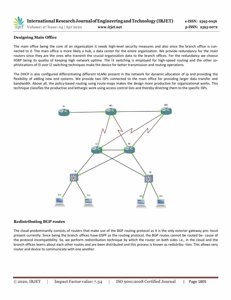
International Research Journal of Engineering and Technology (IRJET) e-ISSN: 2395-0056
p-ISSN: 2395-0072 Volume: 07 Issue: 04 | Apr 2020 www.irjet.net
© 2020, IRJET | Impact Factor value: 7.34 | ISO 9001:2008 Certified Journal | Page 1805
Designing Main Office
The main office being the core of an organization it needs high-level security measures and also since the branch office is con- nected to it. The main office is more likely a hub, a data center for the entire organization. We provide redundancy for the main routers since they are the ones who transmit the crucial organization data to the branch offices. For the redundancy we choose HSRP being its quality of keeping high network uptime. The l3 switching is employed for high-speed routing and the other so- phistications of l3 over l2 switching techniques make the device for better transmission and routing operations.
The DHCP is also configured differentiating different VLANs present in the network for dynamic allocation of ip and providing the flexibility of adding new end systems. We provide two ISPs connected to the main office for providing larger data transfer and bandwidth. Above all, the policy-based routing using route-maps makes the design more productive for organizational works. This technique classifies the productive and lethargic work using access control lists and thereby directing them to the specific ISPs.
Redistributing BGP routes
The cloud predominantly consists of routers that make use of the BGP routing protocol as it is the only exterior gateway pro- tocol present currently. Since being the branch offices have OSPF as the routing protocol, the BGP routes cannot be routed be- cause of the protocol incompatibility. So, we perform redistribution technique by which the router on both sides i.e., in the cloud and the branch offices learns about each other routes and are been distributed and this process is known as redistribu- tion. This allows very router and device to communicate with one another.

International Research Journal of Engineering and Technology (IRJET) e-ISSN: 2395-0056
p-ISSN: 2395-0072 Volume: 07 Issue: 04 | Apr 2020 www.irjet.net
© 2020, IRJET | Impact Factor value: 7.34 | ISO 9001:2008 Certified Journal | Page 1806
Outputs
Fig-1: ROAS sub interface output
Fig-2: OSPF neighbor
Fig-3: OSPF routes

International Research Journal of Engineering and Technology (IRJET) e-ISSN: 2395-0056
p-ISSN: 2395-0072 Volume: 07 Issue: 04 | Apr 2020 www.irjet.net
© 2020, IRJET | Impact Factor value: 7.34 | ISO 9001:2008 Certified Journal | Page 1807
Fig-4: NAT addresses
Fig-5: HSRP report
Fig-6: policy-based routing using route maps

International Research Journal of Engineering and Technology (IRJET) e-ISSN: 2395-0056
p-ISSN: 2395-0072 Volume: 07 Issue: 04 | Apr 2020 www.irjet.net
© 2020, IRJET | Impact Factor value: 7.34 | ISO 9001:2008 Certified Journal | Page 1808
CONCLUSION
The need for a well-designed network is always been a major asset for any organization. Creating a network is not a simple task of imbibing all the available protocols, it involves huge care, supervision, management, and confidentiality. The under- standing of requirements and availabilities of an organization and implementing the protocols that are needed in such a way that they are compatible is the best way of building a network. In this paper, we have assumed the ideal network requirements and selected the finest protocols like MPLS, OSPF, HSRP, NAT, VLAN, DHCP and many more to design and provide the security to the network.
REFERENCES
[1] TRILLIUM: Multiprotocol Label Switching (MPLS).
[2] Enovate: Multiprotocol Label Switching (MPLS).
[3] HUAWEI Technologies Proprietary: Quidway MA5200G MPLS Configuration Guide, June 2007.
[4] Alcatel: The Role of MPLS Technology In Next Generation Networks, October 2000.
[5] Technical University of Madrid: Network Convergence over MPLS.
[6] COMPREHENSIVE MPLS VPN SOLUTIONS: Meeting the Needs of Emerging Services with Innovative Technology. 3510324- 003-EN.pdf, Jan 2010.
[7] IP Solution Center-MPLS VPN: Deploying MPLS VPN Service. White Paper, Cisco Systems, Inc. [17] Cisco MPLS based VPNs: Equivalent to the security of Frame Relay and ATM, White Paper. March 30, 2001.
[8] Neha Grang and Anuj Gupta, “Compare OSPF Routing Protocol with other Interior Gateway Routing Protocols”, IJEBEA 13- 147, Vol 1, pp.2-4, 2013
[9] Nikhil Hemant Bhagat,” Border Gateway Protocol –A Best Performance Protocol When Used For External Routing than In- ternal Routing”, Vol 1, pp.1-2, 2012
[10] A.Alaettinoglu,C.Villamizar,E.Gerich,D.Kessens,D.Meyer, T. Bates, D. Karrenberg, M. Terpstra, “Routing policy specifica- tion language (RPSL),” IETF RFC 2622, June 1999.
[11] T. Griffin, A. Jaggard, V. Ramachandran, “Design principles of policy languages for path vector protocols,” in Proc. ACM SIG- COMM, August 2003.
[12] L. Subramanian, M. Caesar, C. Ee, M. Handley, Z. Mao, S. Shenker, I. Stoica, “HLP: A next-generation interdomain routing protocol,” in Proc. ACM SIGCOMM, August 2005