Design Vehicle's Influence to the Geometric Design of...
17
Chan and Livingston 1 DESIGN VEHICLE’S INFLUENCE TO THE GEOMETRIC DESIGN OF TURBO- ROUNDABOUTS Steven Chan Transoft Solutions Inc. 13575 Commerce Parkway Richmond, BC, Canada V6V 2L1 Phone: 604-244-8387; E-mail: [email protected] Robert Livingston Transoft Solutions Inc. 13575 Commerce Parkway Richmond, BC, Canada V6V 2L1 Phone: 604-244-8387; E-mail: [email protected] Submitted for consideration for presentation at the 2014 International Roundabout Conference, April 7 th -10 th , 2014.
Transcript of Design Vehicle's Influence to the Geometric Design of...

Chan and Livingston
1
DESIGN VEHICLE’S INFLUENCE TO THE GEOMETRIC DESIGN OF TURBO-
ROUNDABOUTS
Steven Chan
Transoft Solutions Inc. 13575 Commerce Parkway
Richmond, BC, Canada V6V 2L1 Phone: 604-244-8387; E-mail: [email protected]
Robert Livingston
Transoft Solutions Inc.
13575 Commerce Parkway Richmond, BC, Canada V6V 2L1
Phone: 604-244-8387; E-mail: [email protected]
Submitted for consideration for presentation at the
2014 International Roundabout Conference, April 7th-10th, 2014.

Chan and Livingston
2
ABSTRACT
The geometric design for turbo-roundabouts can be more complex in nature. While the definition of turbo-roundabout has not been standardized among the United States, Netherlands, and
Germany, a common trait with any turbo-roundabout is that they involve a design vehicle navigating entry maneuvers, spiral circulatory maneuvers, and exit maneuvers. In essence, the design vehicle swept path becomes a crucial factor that assists in the definition of the geometric
design and lane markings. Resulting from the swept path of the chosen design vehicle, many aspects of the geometric design are influenced including entry and exit curb radius, circulating
lane width, entry and exit widths, mountable/traversable width, central island shape, and splitter island shape. Specifically in a turbo-roundabout, the circulatory lane requires a vehicle to traverse in a spiral manner from a smaller circulatory radius to an increasingly larger circulatory
radius. When a vehicle is simulated along such path, the offtracking will vary accordingly. This significance is portrayed in the Dutch guideline to Turbo-Roundabout as it prescribes a lane
width that varies. When practitioners apply this type of design in other regions, the geometric design will need to conform to the requirements of the local design vehicle. In this study, the focus is on identifying the relationships between design vehicle paths, spiral circulatory lane
widths, and opening width. Recommendations on the minimum values for constructing the different turbo-roundabout types (basic, egg, and knee) according to design vehicles such as the
AASHTO single unit [SU-9], bus [BUS-12] and semitrailer [WB-12] are summarized.

Chan and Livingston
3
INTRODUCTION
Two main reasons for the widespread adoption of this type of roundabout in the Netherlands are due to the operational and safety benefits of turbo-roundabouts– (1). Turbo-roundabout and its
variations are being explored and adopted in different regions like United States (2), Canada (3), Germany (4), Finland (5), Portugal (5), Norway (5), Slovenia (6) and United Kingdom (7). As the individual practitioners adopt the Dutch design in their regions, better guidance is needed for
defining the more complicated geometric design and regionalizing the design to local conditions. Because the Dutch guideline provides standardized values for the parameters of the geometric
design, the same practice cannot be easily adopted when the design vehicles differ by region. As with any roundabout, design vehicles and their swept path have a strong influence on the geometric design because the roundabout must accommodate the design vehicles. Further
exploring the relationship between vehicle swept path and geometric design, this study is focused on identifying opportunities to advance the geometric design guidelines so designers from United
States or other regions can adopt the Dutch approach of turbo-roundabout. Firstly, the influences of design vehicles on the specific geometric elements found in common types of Dutch turbo-roundabouts are determined. Secondly, suitable geometric values are measured based on the
swept path requirements of the common design vehicles found in United States such as AASHTO SU-9, BUS-12 and WB-12. Recommendations on the minimum values for the
geometric elements in relation to the chosen vehicles are summarized in the findings.
LITERATURE REVIEW
The turbo-roundabout was first introduced by Fortuijn in the late 1990’s as a safer and more
efficient alternative to the standard multi- lane roundabouts (1). The geometric design of the turbo-roundabout, defined by Fortuijn, is specified in the Dutch manual (8; 9). The manual provides guidance on the design elements of the turbo-roundabout and summarizes seven types
of turbo-roundabouts with different number of approach legs and lane configurations to handle various capacity requirements (9). These types are referred to as the Basic, Egg, Knee, Spiral,
Rotor, Stretched Knee, and Star with the most common types being the Basic, Knee, and Egg (See Figure 1). A table from the manual outlines the dimensions for the various design features for the basic and knee turbo types (See Table 1). Although the values are provided, it is unclear
to which design vehicle(s) are associated with the recommended dimensions. Despite the missing reference to the specific design vehicle, it is clear that the vehicle swept path is an important
variable. The first step to designing turbo-roundabouts outlined in the manual is selecting widths of the basic elements through swept path analysis (9). For single lane roundabouts, the design manual references three sets of design values for the design vehicles with a standard length
(15.5m) or long length (22m and 27m). However, the exact dimensions of the vehicles are not explicitly defined. Without the exact dimensions for the wheelbase, steering lock angle, and
turning radius, the approximation of swept path and offtracking is not possible (16).

Chan and Livingston
4
FIGURE 1 Common types of turbo-roundabout: Basic (left), Egg (center), and Knee
(right)
TABLE 1 Recommended Dimensions of Turbo-Roundabout from Dutch Manual (9)
Feature
Radius and measurement
(m)
Rinside of the inner lane(all designs) R1 10.50 12.00 15.00 20.00
ROutside of the inside roadway
(all designs) R2 15.85 17.15 20.00 24.90
RInside of the outside roadway
(turbo-egg-spiral) R3 16.15 17.45 20.30 25.20
Routside of the outside roadway
(turbo-egg-spiral) R4 21.15 22.45 25.20 29.90
Width, inside roadway 5.35 5.15 5.00 4.90
Width, outside roadway 5.00 5.00 4.90 4.70
Width, inside lane 4.70 4.50 4.35 4.25
Width, outside lane 4.35 4.35 4.25 4.05
Lane divider between driving lanes 0.30 0.30 0.30 0.30
Shift of inner arc centres along the translation-axis 5.75 5.35 5.15 5.15
Shift of outer arc centres along the translation-axis 5.05 5.05 4.95 4.75
Largest diameter 47.35 49.95 55.35 64.55
Smallest diameter 42.60 45.18 50.64 59.99
R, Curve entry and exit 10.00 10.00 10.00 10.00
R, Curve lane divider entry 12.00 12.00 12.00 12.00
R, Curve lane divider exit 15.00 15.00 15.00 15.00
Width, overrun area for vehicles with length 22 to 27m 5.00 5.00 5.00 max. 5.00
Speed, passenger car (km/h] 37-41 37-39 38-39 40

Chan and Livingston
5
Further to the recommended dimensions of the turbo-roundabout, the manual relates these values
to the construction of the “turbo-block”. A “turbo-block” illustrates the layout of the nested spiral lanes and corresponding central island shape. The nested spiral lanes are comprised of
circular arcs with consecutive larger radii. The effect of using circular arcs with increasing radii simulates the effect of a spiral. In a different study, Guiffre suggested that the construction of the spiral lane can be based on the Archimedean spiral as an alternative to the method specified in
the Dutch manual (10). From the Dutch manual, four turbo-block types are described to accommodate the seven turbo-roundabout types. Each turbo-block varies by the number of
translation axes ranging from one to four axes (see Figure 2).
FIGURE 2 Turbo-blocks detail with one to four axes.
A review of the current research shows that the turbo-block helps define the central island shape based on the number of nested spiral lanes and lane dividers. While not explicitly described in
the manual, the number of translation axes directly relates to the number of nested spiral lanes in a turbo-roundabout. For example, relating to common turbo types, one nested spiral with one spiral start refers to the example of the Knee layout while two nested spirals with two spiral
starts refers to the example of the Basic and Egg layouts (See Figure 3). The spiral lane element is a significant feature of the turbo-roundabout as it guides the vehicle entering and exiting the
circulatory lanes in a controlled manner where the lane is eventually dropped (See Figure 3). Further to this, raised lane dividers are used to encourage vehicles to stay in the lanes at low driving speeds; however, this feature is not applied in Germany due to safety concerns (4, 9).
The starting positioning of the lane dividers dictates the opening width of the spiral lane. The manual does not describe the opening width and the associated dimension (See Figure 4).When
examining the construction of the spiral lanes, another important feature is the varying lane widths. The starting width of the spiral lane is always larger than the ending width. In other words, the lane width decreases as the lane spirals out. The manual associates this behavior to the
vehicle off-tracking characteristic where vehicle will off-track less on a larger turning radius than a smaller turning radius (9). As for the truck overrun area or truck apron at the central island, the
Dutch manual suggests the width should be based on the design vehicle requirement and recommends a maximum value of 5.0m.

Chan and Livingston
6
FIGURE 3 Spiral lanes for Basic (left) and Egg (right) layouts.
FIGURE 4 Opening width of spiral lane.
In the United States, the national FWHA guideline (2) and various state supplemental guidelines (12; 13; 14) have not provided detailed information on the geometric design of the turbo-
roundabouts or multi- lane roundabouts with spiral transitions. The FHWA guideline (2) only references the Dutch design of turbo-roundabouts as a type of multi- lane roundabout and pinpoints two features that are found in a turbo-roundabout: (a) perpendicular entries to the
circulatory roadway and (b) raised lane dividers for exit path guidance. A third prominent feature that was neglected but should be noted is that a turbo-roundabout is designed to have one or
more spiral circulatory lanes (8). Although the spiral lane is a key feature to a turbo-roundabout, it is not exclusive to this roundabout type. The spiraling lane feature is also found in multi-lane roundabouts with spiral transitions (2). These augmented multi- lane roundabouts, either defined
by spiral markings or an extended central island (See Figure 5), will guide vehicles in reaching

Chan and Livingston
7
the intended exits without a lane-change maneuver. Moreover, the guideline only mentions that the spiral transitions should be defined to help vehicles flow naturally but does not provide
further guidance on the construction of the spiral lanes. A clear classification of roundabouts with spiral lane is not found in the FHWA guideline.
FIGURE 5 Example of multi-lane roundabout with spiral transitions (FHWA).
In the FHWA guideline (2), the relationship between the design vehicle and the geometric design
of a single or double lane roundabout is addressed in several areas. Firstly, the FHWA guideline states that circulatory lane widths should be determined according to the AASHTO policy (11) to ensure the width satisfies the 0.3m minimum (or 0.6m preferred) clearance condition between
the outside edges of the vehicle’s tire track to the curb line. Secondly, the guideline states that the truck apron width should be determined by the larger design vehicle (e.g. AASHTO WB-19
or WB-20) while the circulatory lane width should be defined to constrain speed for a bus (e.g. AASHTO BUS-12) or semitrailer (e.g. AASHTO WB-15) depending on the appropriate design vehicle for the site. While the common design vehicles specified in the guideline include of
AASHTO BUS-12, WB-15, and WB-20, other vehicles were mentioned to be considered as the chosen design vehicle such as emergency vehicles, fire engines, transit vehicles, single unit
delivery trucks, garbage trucks, or even larger moving trucks. For the more extreme cases with larger vehicles, Russell et al. analyzed the impacts of oversized and overweight vehicles on the geometric design of a roundabout and concluded that the design vehicle’s body and tire tracks
could impact different areas of the geometric design (15). Using AutoTURN (a turning simulation tool that illustrates design vehicle swept path) and TORUS (a roundabout design tool
that utilizes swept path to derive the geometric design), Russell et al. suggested that the tire tracks of the swept path could define extra traversable area while the vehicle body could indicate areas requiring removable signage (15; 16; 17).
Upon reviewing the available literature, it appears that the Dutch guideline is the source
document that describes the geometric design of a Dutch turbo-roundabout while the FHWA guideline from the United States pinpoints the importance of considering design vehicle swept

Chan and Livingston
8
path but have does not provide details on the geometric design of turbo-roundabouts or multi-lane roundabouts with spiral transitions. Further research and guidance is needed to relate design
vehicle influences to the construction of a turbo-roundabout. This study is focused on the influences of design vehicles on the geometric design of turbo-roundabout or alike. Geometric
design values and parameters corresponding to the common AASHTO design vehicles are recommended.
METHODOLOGY
From the literature review, it is evident that the spiral lane widths and spiral opening width are governed by the design vehicle swept path. To determine the exact influence of the chosen design vehicle to the spiral lane widths, a vehicle swept path analysis tool like AutoTURN was
used to determine the tire tracks extents and offtracking as a vehicle was simulated along a path containing consecutively larger radii. While maintaining the prescribed offsets from AASHTO of
0.3m on each side of the vehicle simulation, the varying lane widths were observed. Following the Dutch framework of constructing turbo-roundabout based on the general concept of turbo-blocks, new turbo-blocks were constructed to account for the specific design vehicles and their
offtracking requirements. A series of test cases were simulated for the Basic, Egg, and Knee turbo type with varying design vehicles and roundabout sizes. Design vehicles such as AASHTO
SU-9, BUS-12, WB-12 were chosen as these vehicles have overall length less than the standard length of 15.5m prescribed in the Dutch manual. Hypothetically, one would assume the roundabout dimensions would accommodate the chosen AASHTO vehicles. Following data
extraction, the dimensions from the test cases were compared against the values prescribed in the Dutch manual. In summary, the following steps were taken for this study.
Steps:
1. Create a turbo-block layout with one primary axis according to the Dutch approach for a
given central island radius (e.g. 10.5m) 2. Determine the swept path width of the design vehicles when it maneuvers along different
turning radii. The turning radii includes of the entry path radius and circulating path radius in the spiral lanes)
3. Identify the calculated swept path widths at the opening width and varying spiral lane
widths. 4. Determine the impact to the previous parameters by varying the central island radius to
12.0m, 15.0m, and 20m. 5. Repeat steps 2 to 5 to evaluate the effect of different design vehicles. 6. Repeat all steps on a turbo-block layout with 2 primary axes
7. Compare findings to determine relationships
Assumptions:
For the analysis, the following assumptions were made for setting the control parameters.
Turbo Types The scope of this study has been limited to the 3 turbo types: Basic, Knee, and Egg. The concept
of the corresponding turbo-blocks from the Dutch manual was used.

Chan and Livingston
9
For consistency, all roundabout were created with orthogonal approach legs with radial alignment. The axis rotation is set at 25 degrees (see Figure 7).
Design Vehicles
The design vehicles selected for this study are the SU-9, BUS-12, and WB-12 from the AASHTO 2011 Green book (18). With the assumption that the Dutch manual recommended design values according to the vehicle of standard length (15.5m), the AASHTO vehicles with
lengths less than the standard length were chosen (see Figure 6).
FIGURE 6 The selected design vehicles for analysis.
Central Island Radius
The Central Island Radius is defined as the radius of the inside edge of the innermost spiral circulatory lane. Values of 10.5m, 12.0m, 15.0m, and 20.0m are adopted from the Dutch manual
(See Table 1).
Entry Path Radius
The Entry Path Radius is the radius of the centerline of the vehicle travelling from the leg to the spiral circulatory lane. This radius may vary according to the chosen design vehicle. For the
purpose of this study, the value is set at 12.0m as a value attainable by each of the chosen vehicles. Also, 12.0m is recommended in the Dutch manual (9).
Lane Separator To maintain vehicles within their defined travel way, the spiraling lanes are separated by a
feature known as the Lane Separator. The Lane Separator is a finite width and becomes part of the defining geometry. A value of 0.3m is adopted from the Dutch manual (See Table 1).
Lane Width In accordance with AASHTO policy, a minimum clearance of 0.3m (preferably 0.6m) should be
provided between the outside edge of the vehicle’s tire and the curb line. For this study, a minimum clearance of 0.3m is applied on both sides of the tire tracks for defining the spiral circulatory lane widths. At the approach leg, a 0.6m clearance was applied between the median
and the closest vehicle tire track (See Figure 7). The lane widths are measured along the axis as defined by the turbo-block.

Chan and Livingston
10
DATA ANALYSIS
To analyze the different scenarios, turbo-blocks had to be reconstructed according to the design vehicle swept path requirement. A sample test case is shown in Figure 7. This figure portrays the
new turbo-block with one translation axis defined by the AASHTO WB-12. The design vehicle is simulated for three revolutions. Note that a turbo-roundabout will not necessarily require three revolutions of circulating lanes; therefore, only the relevant lane widths (i.e. W1, W2, W3, and
W4) were extracted along the translation axis for analysis. In addition, the spiral opening width at the entry were extracted. The values were compared against the different test cases.
FIGURE 7 A new turbo-block constructed from vehicle swept path dimensions.
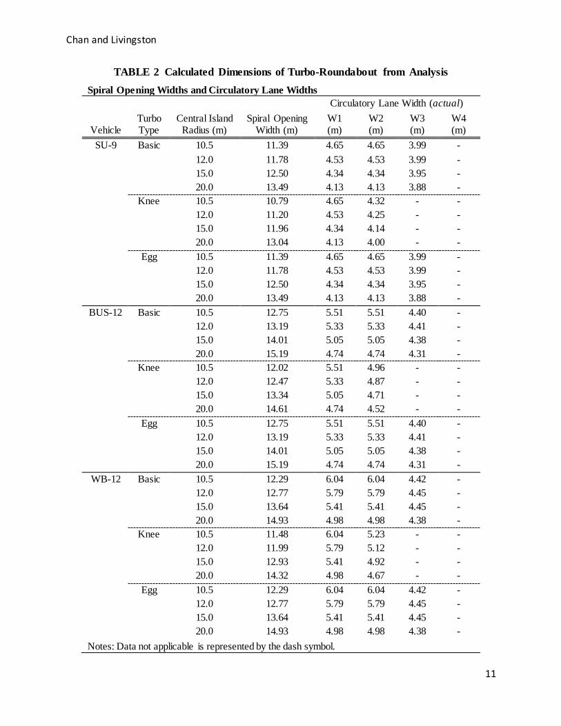
The following table summarizes the data extracted from the reconstructed turbo-roundabouts.
For each test case, the following was reported: vehicle, turbo type, central island radius, spiral opening width, circulatory lane width at position W1, W2, W3, and W4.
Chan and Livingston
11
TABLE 2 Calculated Dimensions of Turbo-Roundabout from Analysis
Spiral Opening Widths and Circulatory Lane Widths
Vehicle Turbo Type
Central Island Radius (m)
Spiral Opening Width (m)
Circulatory Lane Width (actual)
W1 (m)
W2 (m)
W3 (m)
W4 (m)
SU-9 Basic 10.5 11.39 4.65 4.65 3.99 -
12.0 11.78 4.53 4.53 3.99 -
15.0 12.50 4.34 4.34 3.95 -
20.0 13.49 4.13 4.13 3.88 -
Knee 10.5 10.79 4.65 4.32 - -
12.0 11.20 4.53 4.25 - -
15.0 11.96 4.34 4.14 - -
20.0 13.04 4.13 4.00 - -
Egg 10.5 11.39 4.65 4.65 3.99 -
12.0 11.78 4.53 4.53 3.99 -
15.0 12.50 4.34 4.34 3.95 -
20.0 13.49 4.13 4.13 3.88 -
BUS-12 Basic 10.5 12.75 5.51 5.51 4.40 -
12.0 13.19 5.33 5.33 4.41 -
15.0 14.01 5.05 5.05 4.38 -
20.0 15.19 4.74 4.74 4.31 -
Knee 10.5 12.02 5.51 4.96 - -
12.0 12.47 5.33 4.87 - -
15.0 13.34 5.05 4.71 - -
20.0 14.61 4.74 4.52 - -
Egg 10.5 12.75 5.51 5.51 4.40 -
12.0 13.19 5.33 5.33 4.41 -
15.0 14.01 5.05 5.05 4.38 -
20.0 15.19 4.74 4.74 4.31 -
WB-12 Basic 10.5 12.29 6.04 6.04 4.42 -
12.0 12.77 5.79 5.79 4.45 -
15.0 13.64 5.41 5.41 4.45 -
20.0 14.93 4.98 4.98 4.38 -
Knee 10.5 11.48 6.04 5.23 - -
12.0 11.99 5.79 5.12 - -
15.0 12.93 5.41 4.92 - -
20.0 14.32 4.98 4.67 - -
Egg 10.5 12.29 6.04 6.04 4.42 -
12.0 12.77 5.79 5.79 4.45 -
15.0 13.64 5.41 5.41 4.45 -
20.0 14.93 4.98 4.98 4.38 -
Notes: Data not applicable is represented by the dash symbol.

Chan and Livingston
12
FINDINGS
From this study, the findings include the geometric design parameters, the relationship between
the central island radius and spiral lane widths, and the relationship between the central island radius and opening width. The impacts from the design vehicle on the geometric parameters are highlighted.
Geometric Design Parameters
Spiral Circulatory Lane Widths From the construction of the turbo-block, the spiral circulatory lane width varies along its path
starting at W1. Once the first lane width, W1, is calculated from the central island radius, the subsequent widths are calculated based on the first width. At every instance the lane crosses the
axis; the width could vary and decrease from W2 to W3 and W3 to W4 and so on. With the new turbo-block, each width is calculated as a function of the swept path width, minimum clearances, circulatory path radius, and lane separator width. This is the key difference as compared to the
Dutch approach where these widths are specified. Figure 8 and 9 present the lane width measurements along the axis. Table 2 presents the calculated lane widths at W1, W2, W3, and
W4. Opening Width of Spiral Lane
The opening width is a measurement of the arc length at the opening of the spiral circulatory lane. It is measured from the extension of the inbound leg geometry to the intersection of 0.3m
offset from the outside edge of the vehicle’s tire track and the outside edge of the first lane separator. The Dutch manual does not provide guidance on this value. From this study, it is seen that the opening width is a function of the swept path width, minimum clearances, the entry path
radius, and the circulatory path radius, and lane separator width. Figure 10 illustrates the significance of the swept path influencing the opening width when the entry and circulatory path
radii vary. Truck Apron or Traversable Area
The Truck Apron is a mountable (traversable or overrun) area, within the central island intended to accommodate the swept area of larger vehicles. This is a common design element within a
roundabout (turbo or standard). A larger design vehicle would assist in determining the truck apron width. Hypothetically, the larger vehicle will maneuver within the spiral circulatory lane defined for the dominant design vehicle. If the swept path width of the larger vehicle is greater
than the swept path width of the dominant design vehicle, then the difference in width would be set as the truck apron width. For this paper, the calculation of the truck apron width is excluded.

Chan and Livingston
13
FIGURE 7 Geometric design parameters of a turbo-roundabout.
FIGURE 8 Turbo block relationship to geometric design parameters.

Chan and Livingston
14
FIGURE 9 Lane width relationship to geometric design parameters.
FIGURE 10 Opening width of spiral lane relationship to central island radius
Central Island Radius and Spiral Lane Widths Relationship
The relationship between the central island radius and spiral lane width can be defined such that as the central island radius increases, the spiral lane widths decreases. In Table 2, it can be seen
that the spiral lane widths are dependent on the design vehicle and the central island radius but not the type of turbo-roundabout. The Basic, Knee, and Egg types all shared the same lane widths for the selected design vehicle. Also, the minimum values of the W1 lane width for the
different design vehicles, a SU-9, BUS-12, and WB-12 were calculated to be 4.65m, 5.65m, and 6.04, respectively. It is important to note that the Dutch manual recommends a value of 5.35m
for W1 but this width will not accommodate the AASHTO BUS-12 and WB-12. This finding reinforces the need to determine the lane widths according to the chosen design vehicle.
Central Island Radius and Opening Width Relationship

Chan and Livingston
15
From Table 2, the relationship between the central island radius and opening width was observed. As the central island radius increases, the opening width increases. This may be
counter-intuitive due to the known relationship with a vehicle’s swept path width which decreases as the turning radius increases. From our findings, this relationship was observed as a
resulting behavior from the vehicle’s off-tracking as it transitions between the entry path radius and circulatory path radius. Figure 10 illustrates the difference in the rear tire track between the central island radius of 10.5m and 20.0m when the entry path radius is kept constant. From Table
2, the opening width is not dependent on the Turbo types but is dependent on the number of axes in the turbo block. The minimum opening width values were the same for both the Basic and Egg
types as they share the same turbo-block with two translation axes.
CONCLUSION
From the literature review, there are many aspects of geometric design within a turbo-roundabout which are influenced by the swept path. In fact, some of these geometric features including the
spiral circulatory lane are unique to turbo-roundabouts and spiral roundabouts. With the growing adoption of turbo-roundabouts around the world, regional adaptation of this more complex design must be considered. One fundamental design factor is the local standard design vehicles.
This paper has shown that there is a direct correlation between the chosen design vehicle and the geometric definition of the turbo-roundabout including the Basic, Knee, and Egg layouts. It is
also apparent that the existing Dutch guidelines are not recommending values that are appropriate for design vehicles in United States and potentially other regions. Additionally, this paper recommends that future guidelines on turbo-roundabout should consider the significance
of vehicle swept path in a concrete manner. In summary, the spiral circulatory lane and opening width are two geometric features that have a strong relationship with the vehicle swept path but are not clearly defined in the current guidelines. The design process for developing a turbo-
roundabout is more complex over a traditional roundabout and the necessity for considering the design vehicle swept path is paramount.
FURTHER STUDIES 1. Evaluate the effects of the vehicle swept path to the turbo-roundabout when the following
elements vary: a. Deflection of the Approach Leg (e.g. non-radial)
b. Alignment of Approach Leg (e.g. curvilinear) c. Entry Path Radius d. Axis Rotation
2. Vehicle off-tracking and impacts to the overrun areas 3. Evaluate the effects of different design vehicles and establish new turbo blocks for other
regions like Germany or Canada.

Chan and Livingston
16
REFERENCES
[1] Fortuijn, L. Turbo Roundabouts – Design Principles and Safety Performance. Transportation Research Board: Journal of the Transportation Research Board, Vol. 2096,
No. 1, 2009, pp 16-24 [2] Rodegerdts, L., J.Bansen., C. Tiesler, E.J. Knudsen, and M. Myers. Roundabouts: An
Informational Guide, Second Edition – NCHRP Report 672. In, Transportation Research
Board, National Research Council, Washington DC, USA, 2010. [3] Murphy, T. Presentation, TAC Conference & Exhibition, October 14-17, Fredericton, NB
[4] Brilon, W. Studies on Roundabouts in Germany: Lessons Learned. Presented at 3rd International Conference on Roundabouts, Carmel, Indiana, 2011.
[5] Silva, A., S. Santos, and M. Gaspar. Turbo-roundabouts use and design. Presented at
CITTA 6th Annual Conference on Planning Research – Responsive Transports for Smart Mobility, Coimbra, Portugal, 2013.
[6] Tollazzi, T., M. Rencelj, and S. Turnsek. Solvenian Experiences with Alternative Types of Roundabouts – “Turbo” and “Flower” Roundabouts. Presented at 8th International Conference on Environmental Engineering, Vilnius, Lithuania, 2011.
[7] Lingwood, P. Union St Roundabout DfT cycle safety fund, November 27, 2012 [8] CROW, Turborontondes, publicaie 257. Ede, April, 2008.
[9] Royal Haskoning Ministry of Transport, Roundabouts – Application and design – A Practical Manual, Public Works and Water Management Partners for Roads, June, 2009
[10] Guiuffre, O., G. Guierrieri, and A. Grana. Turbo-roundabout General Design Criteria and
Functional Principles: Case Studies from Real World, 4th International Symposium on Highway Geometric Design, Valencia, Spain.
[11] American Association of State Highway and Transportation Officials, A Policy on Geometric Design of Highways and Streets, Washington, DC, 2004.
[12] Florida Department of Transportation. Florida Roundabout Guide. March 1996.
http://www.dot.state.fl.us/trafficoperations/doc_library/pdf/roundabout_guide8_07.pdf, Accessed on Feb. 01, 2014.
[13] Wisconsin Department of Transportation. Roundabout Guide, March 2013. http://dot.wi.gov/safety/motorist/roaddesign/roundabouts/docs/guide-wisdotrab.pdf, Accessed on Feb. 01, 2014.
[14] Kansas Department of Transportation. Kansas Roundabout Guide, Oct 2003. http://www.ksdot.org/burtrafficeng/Roundabouts/Roundabout_Guide/Chapter_1_Introducti
on.pdf, Accessed on Feb. 01, 2014. [15] Russell, E.R., E.D. Landman, and R. Godavarthy. Accommodating Oversize/Overweight
Vehicles at Roundabouts, Kansas State University Transportation Center, Report No. K-
TRAN: KSU-10-, January, 2013. [16] AutoTURN Help Files: Version 8.2. Transoft Solutions Inc., Richmond, B.C., Canada,
2014 [17] TORUS Help Files: Version 4.0. Transoft Solutions Inc., Richmond, B.C., Canada,
2014Canadian Institute of Transportation Engineers, Roundabouts in Canada: A Primer for
Decision-Makers, Technical Liaison Committee, November, 2013 [18] American Association of State Highway and Transportation Officials, A Policy on
Geometric Design of Highways and Streets, Washington, DC, 2011.

Chan and Livingston
17