Topic 3.14 - Organic Synthesis · AQA Chemistry A-level Topic 3.14 - Organic Synthesis Flashcards
Akademisk avhandling som med tillstånd av Kungliga Tekniska Högskolan i Stockholm framlägges till offentlig granskning för avläggande av doktorsexamen i kemi med inriktning mot organisk kemi fredagen den 20 maj kl 10.00 i sal K2, KTH, Teknikringen 28, Stockholm. Avhandlingen försvaras på engelska. Opponent är Professor Jaejung Ko, Korea University, Korea.
Design, Synthesis and Properties of Organic
Sensitizers for Dye Sensitized Solar Cells
Karl Martin Karlsson
Doctoral Thesis
Stockholm 2011

ISBN 978-91-7415-954-7
ISSN 1654-1081
TRITA-CHE-Report 2011:31
© Karl Martin Karlsson
E-print Stockholm
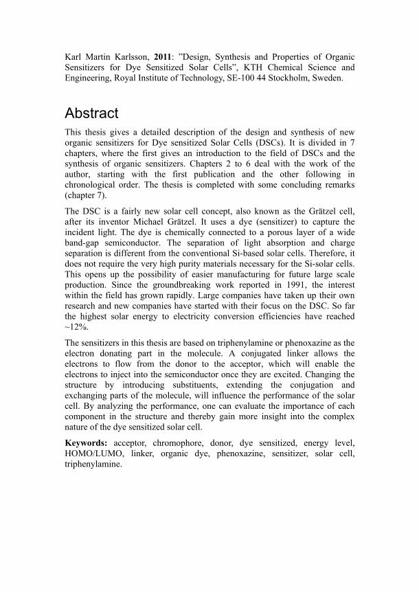
Karl Martin Karlsson, 2011: ”Design, Synthesis and Properties of Organic Sensitizers for Dye Sensitized Solar Cells”, KTH Chemical Science and Engineering, Royal Institute of Technology, SE-100 44 Stockholm, Sweden.
Abstract This thesis gives a detailed description of the design and synthesis of new organic sensitizers for Dye sensitized Solar Cells (DSCs). It is divided in 7 chapters, where the first gives an introduction to the field of DSCs and the synthesis of organic sensitizers. Chapters 2 to 6 deal with the work of the author, starting with the first publication and the other following in chronological order. The thesis is completed with some concluding remarks (chapter 7).
The DSC is a fairly new solar cell concept, also known as the Grätzel cell, after its inventor Michael Grätzel. It uses a dye (sensitizer) to capture the incident light. The dye is chemically connected to a porous layer of a wide band-gap semiconductor. The separation of light absorption and charge separation is different from the conventional Si-based solar cells. Therefore, it does not require the very high purity materials necessary for the Si-solar cells. This opens up the possibility of easier manufacturing for future large scale production. Since the groundbreaking work reported in 1991, the interest within the field has grown rapidly. Large companies have taken up their own research and new companies have started with their focus on the DSC. So far the highest solar energy to electricity conversion efficiencies have reached ~12%.
The sensitizers in this thesis are based on triphenylamine or phenoxazine as the electron donating part in the molecule. A conjugated linker allows the electrons to flow from the donor to the acceptor, which will enable the electrons to inject into the semiconductor once they are excited. Changing the structure by introducing substituents, extending the conjugation and exchanging parts of the molecule, will influence the performance of the solar cell. By analyzing the performance, one can evaluate the importance of each component in the structure and thereby gain more insight into the complex nature of the dye sensitized solar cell.
Keywords: acceptor, chromophore, donor, dye sensitized, energy level, HOMO/LUMO, linker, organic dye, phenoxazine, sensitizer, solar cell, triphenylamine.

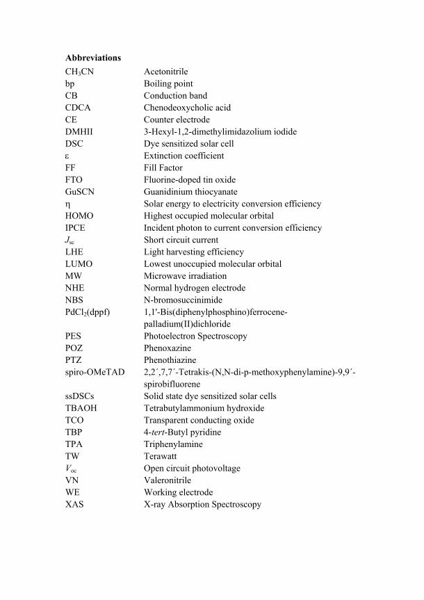
Abbreviations CH3CN Acetonitrile bp Boiling point CB Conduction band CDCA Chenodeoxycholic acid CE Counter electrode DMHII 3-Hexyl-1,2-dimethylimidazolium iodide DSC Dye sensitized solar cell ε Extinction coefficient FF Fill Factor FTO Fluorine-doped tin oxide GuSCN Guanidinium thiocyanate η Solar energy to electricity conversion efficiency HOMO Highest occupied molecular orbital IPCE Incident photon to current conversion efficiency Jsc Short circuit current LHE Light harvesting efficiency LUMO Lowest unoccupied molecular orbital MW Microwave irradiation NHE Normal hydrogen electrode NBS N-bromosuccinimide PdCl2(dppf) 1,1'-Bis(diphenylphosphino)ferrocene-
palladium(II)dichloride PES Photoelectron Spectroscopy POZ Phenoxazine PTZ Phenothiazine spiro-OMeTAD 2,2´,7,7´-Tetrakis-(N,N-di-p-methoxyphenylamine)-9,9´-
spirobifluorene ssDSCs Solid state dye sensitized solar cells TBAOH Tetrabutylammonium hydroxide TCO Transparent conducting oxide TBP 4-tert-Butyl pyridine TPA Triphenylamine TW Terawatt Voc Open circuit photovoltage VN Valeronitrile WE Working electrode
XAS X-ray Absorption Spectroscopy
List of Publications
This thesis is based on the following papers, referred to in the text by their Roman numerals I-VI:
I. Tuning the HOMO and LUMO Energy Levels of Organic Chromophores for Dye Sensitized Solar Cells Daniel P. Hagberg, Tannia Marinado, Karl Martin Karlsson, Kazuteru Nonomura, Peng Qin, Gerrit Boschloo, Tore Brinck, Anders Hagfeldt, and Licheng Sun J. Org.Chem. 2007, 72, 9550-9556
II. Molecular Engineering of Organic Sensitizers for Dye-Sensitized Solar Cell Applications Daniel P. Hagberg, Jun-Ho Yum, Hyojoong Lee, Filippo De Angelis, Tannia Marinado, Karl Martin Karlsson , Robin Humphry-Baker, Licheng Sun, Anders Hagfeldt, Michael Grätzel, and Md. K. Nazeeruddin J. Am.Chem.Soc. 2008, 130,6259-6266
III. Highly Efficient Organic Sensitizers for Solid-State Dye-Sensitized Solar Cells Soo-Jin Moon, Jun-Ho Yum, Robin Humphry-Baker, Karl Martin Karlsson, Daniel P. Hagberg, Tannia Marinado, Anders Hagfeldt, Licheng Sun, Michael Grätzel, and Md K. Nazeeruddin J. Phys. Chem. C. 2009, 113, 16816–16820.
IV. Triphenylamine Based Organic Chromophores Containing Two Anchoring Groups for Dye Sensitized Solar Cells Karl Martin Karlsson, Xiao Jiang, Susanna Kaufmann, Erik Gabrielsson, Erik Martin Jesper Johansson, Tannia Marinado, Håkan Rensmo, Anders Hagfeldt, and Licheng Sun Submitted manuscript
V. Phenoxazine Dyes for Dye Sensitized Solar Cells; Relationship Between Molecular Structure and Electron Lifetime Karl Martin Karlsson, Xiao Jiang, Susanna Kaufmann, Erik Gabrielsson, Håkan Rensmo, Anders Hagfeldt, and Licheng Sun Accepted in Chemistry - A European Journal.
VI. Modifying the Energy Levels in Phenoxazine Based Sensitizers for Dye Sensitized Solar Cells Karl Martin Karlsson, Xiao Jiang, Haining Tian, Erik Gabrielsson, Anders Hagfeldt, and Licheng Sun Preliminary manuscript
Papers not included in this thesis:
VII. A light-Resistant Organic Sensitizer for Solar-Cell applications Jun-Ho Yum, Daniel P. Hagberg, Soo-Jin Moon, Karl Martin Karlsson, Tannia Marinado, Licheng Sun, Anders Hagfeldt, Mohammad K. Nazeeruddin, and Michael Grätzel Angew. Chem. Int. Ed. 2009, 48, 1576 –1580
VIII. How the Nature of Triphenylamine-Polyene Dyes in Dye-Sensitized Solar Cells Affects the Open-Circuit Voltage and Electron Lifetimes Tannia Marinado, Kazuteru Nonomura, Jarl Nissfolk, Martin. K. Karlsson, Daniel P. Hagberg, Licheng Sun, Shogo Mori, and Anders Hagfeldt Langmuir 2010, 26(4), 2592–2598
IX. Stable Dye-sensitized Solar Cells based on Organic Chromophores and Ionic Liquid Electrolyte Daibin Kuang, Pascal Comte, Shaik. M. Zakeeruddin, Daniel P. Hagberg, Karl Martin Karlsson, Licheng Sun, Md. K. Nazeeruddin, and Michael Grätzel Accepted in Solar Energy Materials and Solar Cells
X. Highly Efficient Solid State Dye-sensitized Solar Cells Based on Triphenylamine Dyes Xiao Jiang, Karl Martin Karlsson, Erik Gabrielsson, Erik M. J. Johansson, Maria Quintana, Martin H. Karlsson, Licheng Sun, Gerrit Boschloo, and Anders Hagfeldt Accepted in Advanced Functional Materials
Table of Contents
Abstract
Abbreviations
List of Publications
1 Introduction .......................................................................................................... 1 1.1 The Dye Sensitized Solar Cell ............................................................................... 2 1.1.1 Background ............................................................................................................ 2 1.1.2 The Configuration of the DSC................................................................................ 3 1.1.3 The Working Electrode (WE) ................................................................................. 4 1.1.4 Sensitizer ................................................................................................................ 4 1.1.5 Counter Electrode (CE) ......................................................................................... 4 1.1.6 Electrolyte .............................................................................................................. 5 1.1.7 Principles of Operation .......................................................................................... 6 1.1.8 Incident Photon to Current Conversion Efficiency (IPCE) .................................... 7 1.1.9 Open Circuit Photovoltage (Voc) ............................................................................ 7 1.1.10 Short Circuit Photocurrent (Jsc) ............................................................................. 7 1.1.11 Fill Factor (FF) ..................................................................................................... 8 1.1.12 Solar Energy to Electricity Conversion Efficiency (η) ........................................... 8 1.1.13 Standard Measurements ......................................................................................... 9 1.2 Sensitizers .............................................................................................................. 9 1.3 Synthesis of Organic Dyes ................................................................................... 11 1.4 The Aim of This Thesis ....................................................................................... 12 2 Tuning the Energy Levels by Changing the Conjugation ............................... 13 2.1 Introduction .......................................................................................................... 13 2.2 Synthesis .............................................................................................................. 14 2.3 Properties of the Sensitizers ................................................................................. 16 2.4 Photovoltaic Performance .................................................................................... 18 2.5 Conclusions .......................................................................................................... 20 3 Adding a Second TPA Moiety ........................................................................... 21 3.1 Introduction .......................................................................................................... 21
3.2 Synthesis .............................................................................................................. 22 3.3 Properties of the Sensitizers ................................................................................. 24 3.4 Photovoltaic Performance .................................................................................... 26 3.5 Solid State Devices .............................................................................................. 28 3.6 Conclusions .......................................................................................................... 28 4 Further Donor Variation for Efficient Solid State DSCs ................................ 29 4.1 Introduction .......................................................................................................... 29 4.2 Synthesis .............................................................................................................. 30 4.3 Properties of the Sensitizers ................................................................................. 32 4.4 Photovoltaic Performance .................................................................................... 34 4.5 Conclusions .......................................................................................................... 35 5 Two Anchor/Acceptor Groups in the Structure .............................................. 36 5.1 Introduction .......................................................................................................... 36 5.2 Synthesis .............................................................................................................. 37 5.3 Properties of the Sensitizers ................................................................................. 39 5.4 Photovoltaic Performance .................................................................................... 42 5.5 Conclusions .......................................................................................................... 44 6 Phenoxazine Based Sensitizers for DSCs ......................................................... 45 6.1 Introduction .......................................................................................................... 45 6.2 Synthesis POZ-series 1 ........................................................................................ 46 6.3 Properties of the Sensitizers ................................................................................. 50 6.4 Photovoltaic Performance .................................................................................... 52 6.5 Synthesis POZ-series 2 ........................................................................................ 55 6.6 Properties of the Sensitizers in POZ series 2 ........................................................ 57 6.7 Photovoltaic Performance .................................................................................... 59 6.8 Conclusions .......................................................................................................... 61 7 Concluding Remarks ......................................................................................... 62 Acknowledgements ......................................................................................................... 64 Appendices ...................................................................................................................... 65 References ....................................................................................................................... 74

1
1 Introduction One of the many challenges we face today is the steady increase in energy consumption. With a constantly growing human population and improved living standards, more energy will be needed, with the result that the worldwide power consumption is expected to double within the next 30 years.1 The availability of energy is not only necessary for people in their daily life, it is also among the major driving forces of the global economy.2 Everything, from politics to economy and even further to individuals, is directly dependent on it. Currently, the total energy usage is about 14 terawatts (TW), where fossil fuel (coal, oil and natural gas) is the main source. There are however concerns on maintaining the usage of fossil fuels as the main source of energy. Basically, energy from fossil fuels faces two problems, the first being the limitation of resources and the second their environmental impact. For these two reasons, there has been an urge to develop sustainable energy solutions. The supply of clean sustainable energy is considered as one of the most important scientific and technical challenges facing humanity in the 21st century.2
Among the different alternative power sources existing today (e.g. nuclear, hydroelectric, geothermal, wind, biomass and solar), solar energy has the most potential.2 In fact, several of the alternative energy sources used today are indirectly derived from solar energy.3 The sun provides the earth with approximately 100 000 TW which is almost 10 000 times more than the current energy consumption.4 The practical global solar potential is about 600 TW.5 This abundance of energy makes solar cells very attractive for electricity production. The solar cell that currently has the largest share in the market is based on crystalline silicon and was first reported by Chapin et al. in 1954.6 Even if the efficiency since then has increased and the production cost decreased, it is still too expensive to be able to compete with the conventional energy sources. This has lead to a great research interest in finding new ways of utilizing the solar energy with cheaper and more efficient methods.
Since the 1950s, several new types of solar cells have been studied and developed. Among them, the dye sensitized solar cell (DSC). The DSC is a very attractive choice for utilizing the solar energy, due to its potentially low production cost. In contrast to conventional systems, where the semiconductor works as both the light absorber and charge carrier, the DSC separates the two functions which facilitate the production of the device. Other advantages with DSCs are flexibility, short energy payback time and relatively high performance at diffuse light conditions.5 It has gained considerable interest from the industry and large companies such as Sony, BASF and Samsung have invested in their own research within the field. Also, new companies have emerged with the main focus on the DSC technology; some of them are Dyesol (Australia), Solaronix (Switzerland) and G24i (Wales). So far, the
2
commercialization has mostly reached prototypes of solar cell modules, material and components for the building and study of small scale cells.
1.1 The Dye Sensitized Solar Cell 1.1.1 Background
The concept of dye sensitization of wide band gap semiconductors started already in the 1960s by the work of Gerischer7 and Tsubomura8 together with their co-workers where they used ZnO as the semiconductor and different dyes such as rose bengal as photosensitizer. However, the efficiencies remained low for many years.9 The breakthrough in the field came when Michael Grätzel and Brian O’Regan presented their results in 1991 with an impressive overall efficiency higher than 7%, using a ruthenium based sensitizer and a porous TiO2 layer as the semiconductor material.10
An important feature of the dye sensitized solar cell is the mesoporous semiconductor layer that gives a high surface area. This increases the light harvesting efficiency (LHE) of the cell. It is necessary, since a planar surface covered with a monolayer of a strongly absorbing sensitizer cannot absorb more than 1% of the light.11
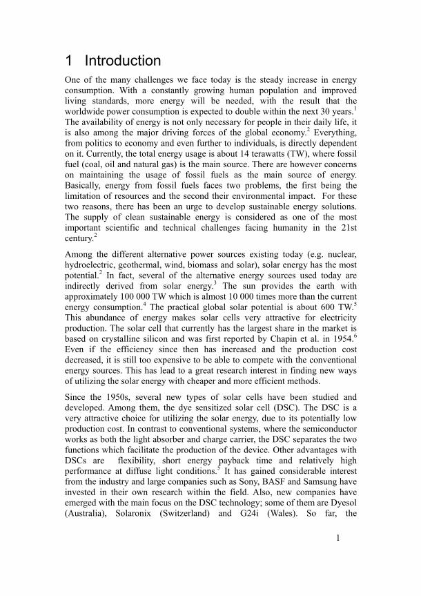
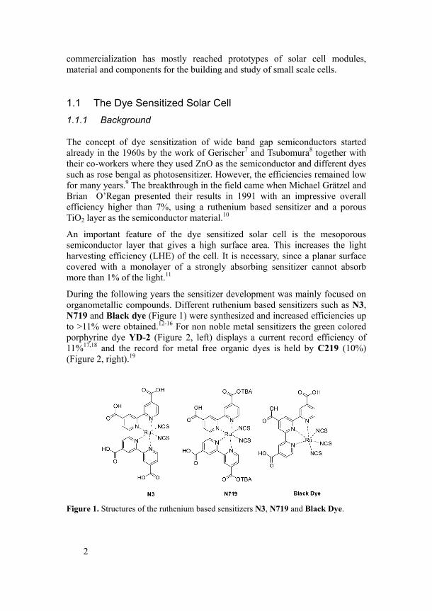
During the following years the sensitizer development was mainly focused on organometallic compounds. Different ruthenium based sensitizers such as N3, N719 and Black dye (Figure 1) were synthesized and increased efficiencies up to >11% were obtained.12-16 For non noble metal sensitizers the green colored porphyrine dye YD-2 (Figure 2, left) displays a current record efficiency of 11%17,18 and the record for metal free organic dyes is held by C219 (10%) (Figure 2, right).19
Figure 1. Structures of the ruthenium based sensitizers N3, N719 and Black Dye.
3
Figure 2. Structures of the porphyrine dye YD-2 and the organic dye C219.
1.1.2 The Configuration of the DSC
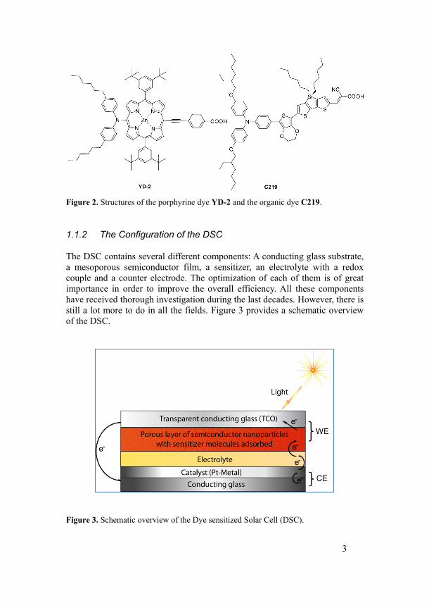
The DSC contains several different components: A conducting glass substrate, a mesoporous semiconductor film, a sensitizer, an electrolyte with a redox couple and a counter electrode. The optimization of each of them is of great importance in order to improve the overall efficiency. All these components have received thorough investigation during the last decades. However, there is still a lot more to do in all the fields. Figure 3 provides a schematic overview of the DSC.
Figure 3. Schematic overview of the Dye sensitized Solar Cell (DSC).
4
1.1.3 The Working Electrode (WE)
The working electrode consists of a mesoporous wide band gap semiconductor layer; the most common material is TiO2. The nanoparticle layer is usually about 10 µm thick and the material is sintered to improve the electronic conduction. The typical particle size is 10-30 nm. The mesoporous layer is deposited on a transparent conducting oxide (TCO), on a glass or plastic substrate. The TCO can for example be fluorine-doped tin oxide (FTO).
1.1.4 Sensitizer
A monolayer of the sensitizer is adsorbed to the surface of the semiconductor by chemical bonding. The function of the sensitizer is to absorb the incident light, inject the excited electron into the semiconductor, and become regenerated by the redox couple in the electrolyte. The sensitizer is further described in part 1.2.
1.1.5 Counter Electrode (CE)
The counter electrode also consists of a conducting layer on a glass or plastic substrate. For efficient regeneration of the redox couple, a layer of platinum is often coated on the substrate. Other counter electrodes such as carbon black and polymers have also been tested20-23
5
1.1.6 Electrolyte
Efficient transport of electrons within the DSC is crucial and many different redox systems (hole-conductors) have been investigated. The most commonly used is the I-/I3
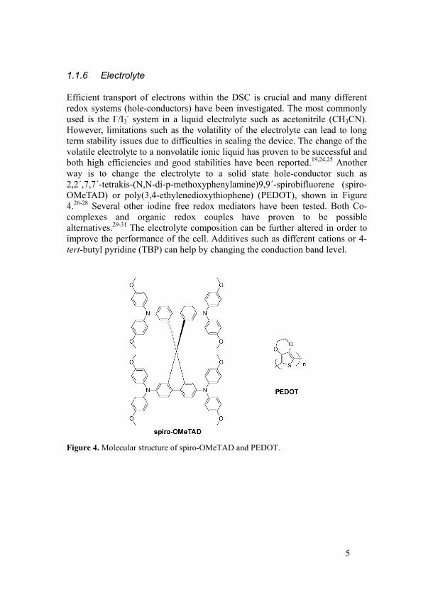
- system in a liquid electrolyte such as acetonitrile (CH3CN). However, limitations such as the volatility of the electrolyte can lead to long term stability issues due to difficulties in sealing the device. The change of the volatile electrolyte to a nonvolatile ionic liquid has proven to be successful and both high efficiencies and good stabilities have been reported.19,24,25 Another way is to change the electrolyte to a solid state hole-conductor such as 2,2´,7,7´-tetrakis-(N,N-di-p-methoxyphenylamine)9,9´-spirobifluorene (spiro-OMeTAD) or poly(3,4-ethylenedioxythiophene) (PEDOT), shown in Figure 4.26-28 Several other iodine free redox mediators have been tested. Both Co-complexes and organic redox couples have proven to be possible alternatives.29-31 The electrolyte composition can be further altered in order to improve the performance of the cell. Additives such as different cations or 4-tert-butyl pyridine (TBP) can help by changing the conduction band level.
Figure 4. Molecular structure of spiro-OMeTAD and PEDOT.
6
1.1.7 Principles of Operation
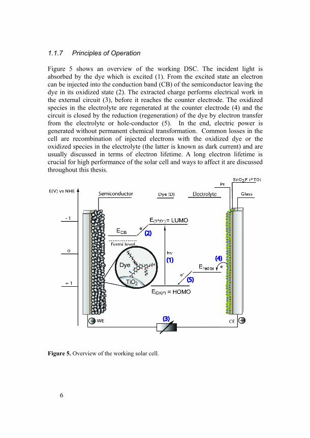
Figure 5 shows an overview of the working DSC. The incident light is absorbed by the dye which is excited (1). From the excited state an electron can be injected into the conduction band (CB) of the semiconductor leaving the dye in its oxidized state (2). The extracted charge performs electrical work in the external circuit (3), before it reaches the counter electrode. The oxidized species in the electrolyte are regenerated at the counter electrode (4) and the circuit is closed by the reduction (regeneration) of the dye by electron transfer from the electrolyte or hole-conductor (5). In the end, electric power is generated without permanent chemical transformation. Common losses in the cell are recombination of injected electrons with the oxidized dye or the oxidized species in the electrolyte (the latter is known as dark current) and are usually discussed in terms of electron lifetime. A long electron lifetime is crucial for high performance of the solar cell and ways to affect it are discussed throughout this thesis.
Figure 5. Overview of the working solar cell.
7
There are some common parameters that are used to characterize the DSC, Incident Photon to current Conversion Efficiency (IPCE), open circuit voltage (Voc), short circuit current (Jsc), fill factor (FF) and solar energy to electricity conversion efficiency (η).
1.1.8 Incident Photon to Current Conversion Efficiency (IPCE)
IPCE is one of the fundamental measurements of the performance of the solar. It is also known as the “external quantum efficiency” and describes how efficiently the light of a specific wavelength is converted to current i.e. (electrons out) / (photons in). The IPCE can be calculated according to equation 1:
1001240(%) ⋅Φ⋅⋅
=in
scJIPCEλ
(1)
Jsc is the short circuit current density, λ is the wavelength of the incident light and Фin is the intensity of the incident light. The factors determining the IPCE can be expressed as:
ccreginjLHEIPCE ηη ⋅⋅Φ⋅= (2)
LHE is the light harvesting efficiency, Фinj, ηreg, and ηcc are the quantum yield of charge injection, dye regeneration and charge collection efficiency, respectively.
1.1.9 Open Circuit Photovoltage (Voc)
The Voc is the difference in potential between the two terminals in the cell under light illumination when the circuit is open. It is dependent on both the Fermi level of the semiconductor and the level of dark current. The theoretical maximum of the cell is determined by the difference between the Fermi level of the semiconductor and the redox potential of the hole-conductor. It is measured when the current through the cell is equal to zero (open circuit).
1.1.10 Short Circuit Photocurrent (Jsc)
Jsc is the photocurrent per unit area (mA/cm2) when an illuminated cell is short circuited. It is dependent on several factors such as the light intensity, light absorption, injection efficiency and regeneration of the oxidized dye. It is strongly related to the IPCE and theoretical values on the Jsc can be calculated from the IPCE spectrum. Figure 6 shows an illustration of current-voltage
8
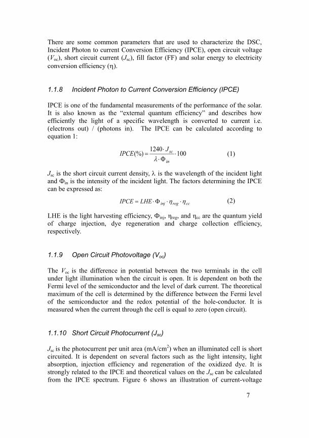
characteristics of a cell under illumination with an external load going from zero load (open-circuit condition) to infinite load (short circuit condition).
Figure 6. Illustration of current-voltage characteristics of a solar cell. Blue line: measured current-voltage curve. Red: area of Voc × Jsc. Green: area of Vmax × Jmax.
1.1.11 Fill Factor (FF)
The fill factor measures the ideality of the device and is defined as the ratio of the maximum power output per unit area to the product of Voc and Jsc (area within the green square divided by the area of the red square in Figure 6). Several factors can influence the ff, such as a high inner resistance (e.g. a bad counter electrode), which will give a low fill factor and a decreased overall efficiency.
1.1.12 Solar Energy to Electricity Conversion Efficiency (η)
The overall solar energy to electricity conversion efficiency of a solar cell is defined as the ratio of the maximum output of the cell divided by the power of the incident light. It can be determined by the photocurrent density measured at short circuit (Jsc), the open circuit photovoltage (Voc), the fill factor of the cell (ff), and the intensity of the incident light (Pin) as shown in eq. 3. Since it is dependent on all the three first factors under standard conditions it is of great importance to optimize each one of them for high overall efficiency.
9
inin
out
PVJ
PP FF ocsc ⋅⋅
==η (3)
1.1.13 Standard Measurements
In order to compare the results of different research groups, a standardization of the measurements is needed. For the illumination of the cell, a standard solar spectrum of AM (air mass) 1.5 G (global) is used. This is derived from the path length the light has to travel through the atmosphere in order to reach the surface. The spectrum is normalized so that the integrated irradiance is 1000 W/m2 (100 mW/cm2).
1.2 Sensitizers When designing a dye for DSC application, there are many important factors that need to be taken into consideration.
i. The dye should have a broad absorption spectrum, preferably all the way into the near-IR in order to harvest as many incident photons as possible.
ii. A high extinction coefficient will enable the use of thinner semiconductor films and still keep a high degree of absorbed photons.
iii. It must bind strongly to the semiconductor surface for long term stability.
iv. The energy levels should match the conduction band of the semiconductor and the redox potential of the hole-conductor.
v. Easy and straightforward synthesis for future large scale production.
vi. Low toxicity and possibility to recycle.
vii. High photo-stability to sustain at least 20 years of use.
viii. Achieve a long lifetime of the injected electrons by blocking the recombination pathways.
The properties of the organic sensitizers can be modified by incorporating different groups into the molecule. By choosing the right design, the sensitizer can be tuned in order to increase the long wavelength absorption, achieve a high extinction coefficient, and shift the energy levels to improve the performance of the solar cell. Organic dyes have the benefits of higher extinction coefficients, easier structural modification, and provide less
10
environmental problems compared to many of the transition metal complexes. On the other hand, they have drawbacks such as relatively narrow absorption bands, higher tendency to aggregate, and often stability problems.
The positions of the energy levels in the sensitizer are of great importance. A small gap between the levels gives the possibility to harvest more low energy photons. This opens up for a high photocurrent output of the cell. However, the different electron transfers in the cell need enough driving force to proceed. The excited state oxidation potential of the dye which is referred to as the lowest unoccupied molecular orbital (LUMO) of the dye, has to be sufficiently higher (more negative) than the conduction band edge of the semiconductor for efficient electron injection. At the same time the ground state oxidation potential or the highest occupied molecular orbital (HOMO) of the dye needs to be lower (more positive) than the redox potential of the redox couple in the electrolyte for efficient regeneration of the oxidized dye. Several reviews describing the development of sensitizers for DSCs including both organic and inorganic dyes have been published during the last years.5,32-34
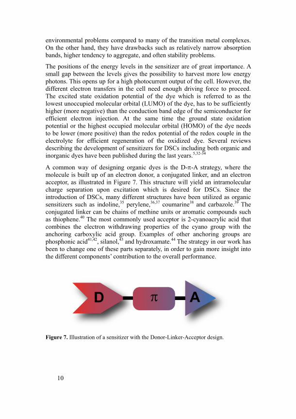
A common way of designing organic dyes is the D-π-A strategy, where the molecule is built up of an electron donor, a conjugated linker, and an electron acceptor, as illustrated in Figure 7. This structure will yield an intramolecular charge separation upon excitation which is desired for DSCs. Since the introduction of DSCs, many different structures have been utilized as organic sensitizers such as indoline,35 perylene,36,37 coumarine38 and carbazole.39 The conjugated linker can be chains of methine units or aromatic compounds such as thiophene.40 The most commonly used acceptor is 2-cyanoacrylic acid that combines the electron withdrawing properties of the cyano group with the anchoring carboxylic acid group. Examples of other anchoring groups are phosphonic acid41,42, silanol,43 and hydroxamate.44 The strategy in our work has been to change one of these parts separately, in order to gain more insight into the different components’ contribution to the overall performance.
Figure 7. Illustration of a sensitizer with the Donor-Linker-Acceptor design.
11
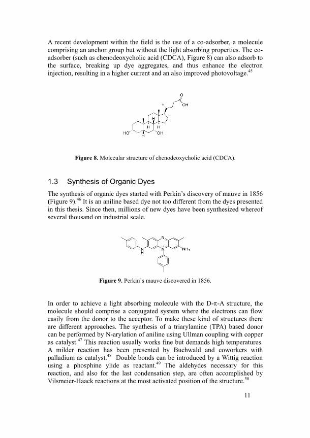
A recent development within the field is the use of a co-adsorber, a molecule comprising an anchor group but without the light absorbing properties. The co-adsorber (such as chenodeoxycholic acid (CDCA), Figure 8) can also adsorb to the surface, breaking up dye aggregates, and thus enhance the electron injection, resulting in a higher current and an also improved photovoltage.45
Figure 8. Molecular structure of chenodeoxycholic acid (CDCA).
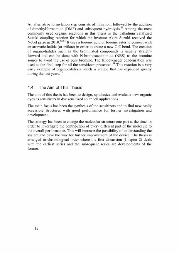
1.3 Synthesis of Organic Dyes The synthesis of organic dyes started with Perkin’s discovery of mauve in 1856 (Figure 9).46 It is an aniline based dye not too different from the dyes presented in this thesis. Since then, millions of new dyes have been synthesized whereof several thousand on industrial scale.
Figure 9. Perkin’s mauve discovered in 1856.
In order to achieve a light absorbing molecule with the D-π-A structure, the molecule should comprise a conjugated system where the electrons can flow easily from the donor to the acceptor. To make these kind of structures there are different approaches. The synthesis of a triarylamine (TPA) based donor can be performed by N-arylation of aniline using Ullman coupling with copper as catalyst.47 This reaction usually works fine but demands high temperatures. A milder reaction has been presented by Buchwald and coworkers with palladium as catalyst.48 Double bonds can be introduced by a Wittig reaction using a phosphine ylide as reactant.49 The aldehydes necessary for this reaction, and also for the last condensation step, are often accomplished by Vilsmeier-Haack reactions at the most activated position of the structure.50
12
An alternative formylation step consists of lithiation, followed by the addition of dimethylformamide (DMF) and subsequent hydrolysis.51 Among the most commonly used organic reactions in this thesis is the palladium catalyzed Suzuki coupling reaction for which the inventor Akira Suzuki received the Nobel prize in 2010.52,53 It uses a boronic acid or boronic ester to connect with an aromatic halide (or triflate) in order to create a new C-C bond. The creation of organo-halides such as the brominated compounds is usually straight-forward and can be done with N-bromosuccinimide (NBS) as the bromine source to avoid the use of pure bromine. The Knoevenagel condensation was used as the final step for all the sensitizers presented.54 This reaction is a very early example of organocatalysis which is a field that has expanded greatly during the last years.55
1.4 The Aim of This Thesis The aim of this thesis has been to design, synthesize and evaluate new organic dyes as sensitizers in dye sensitized solar cell applications.
The main focus has been the synthesis of the sensitizers and to find new easily accessible structures with good performance for further investigation and development.
The strategy has been to change the molecular structure one part at the time, in order to investigate the contribution of every different part of the molecule to the overall performance. This will increase the possibility of understanding the system and pave the way for further improvement of the device. The thesis is arranged in chronological order where the first discussion (Chapter 2) deals with the earliest series and the subsequent series are developments of the former.
13
2 Tuning the Energy Levels by Changing the Conjugation
(Paper I)
2.1 Introduction There are different aspects that must be kept in mind when designing a sensitizer for DSCs. A very important parameter is the energy levels of the dye. For efficient electron injection into the semiconductor conduction band the excited state of the dye (i.e. LUMO) needs to be sufficiently negative, and for regeneration of the oxidized dye, the oxidation potential (i.e. HOMO) needs to be more positive than the redox potential of the redox couple in the electrolyte or hole conductor. At the same time, the gap between the energy levels needs to be small in order to harvest as many incident photons as possible. To find the perfect balance between these contradictions is a great challenge for researchers within the DSC field.
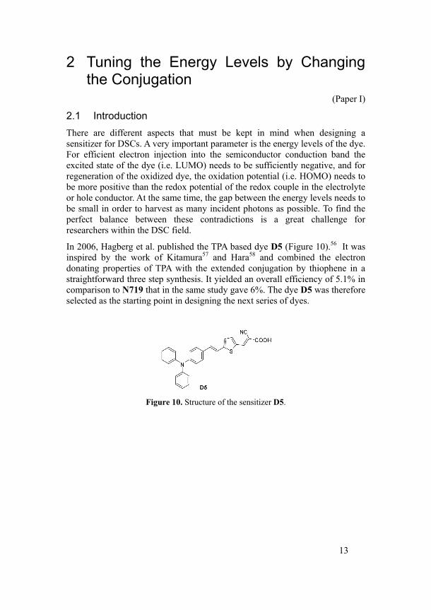
In 2006, Hagberg et al. published the TPA based dye D5 (Figure 10).56 It was inspired by the work of Kitamura57 and Hara58 and combined the electron donating properties of TPA with the extended conjugation by thiophene in a straightforward three step synthesis. It yielded an overall efficiency of 5.1% in comparison to N719 that in the same study gave 6%. The dye D5 was therefore selected as the starting point in designing the next series of dyes.
Figure 10. Structure of the sensitizer D5.
14
Aim of the Study
There are different ways of changing the energy levels of the dye. To be able to understand the influence of the changes, it is a good idea to systematically change only one parameter at a time. This study aimed to vary the conjugated linker in the sensitizer in order to investigate its influence on the spectral properties as well as the performance in the solar cell.
2.2 Synthesis Synthetic Strategy
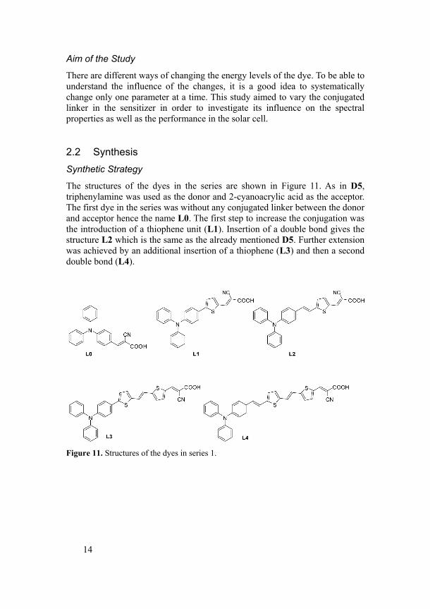
The structures of the dyes in the series are shown in Figure 11. As in D5, triphenylamine was used as the donor and 2-cyanoacrylic acid as the acceptor. The first dye in the series was without any conjugated linker between the donor and acceptor hence the name L0. The first step to increase the conjugation was the introduction of a thiophene unit (L1). Insertion of a double bond gives the structure L2 which is the same as the already mentioned D5. Further extension was achieved by an additional insertion of a thiophene (L3) and then a second double bond (L4).
Figure 11. Structures of the dyes in series 1.
15
Synthetic Procedure
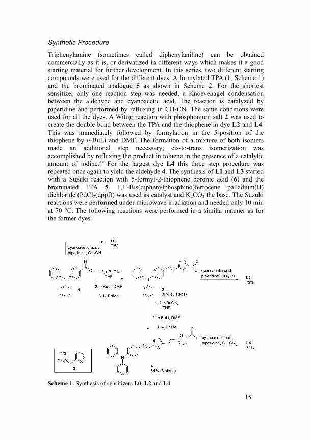
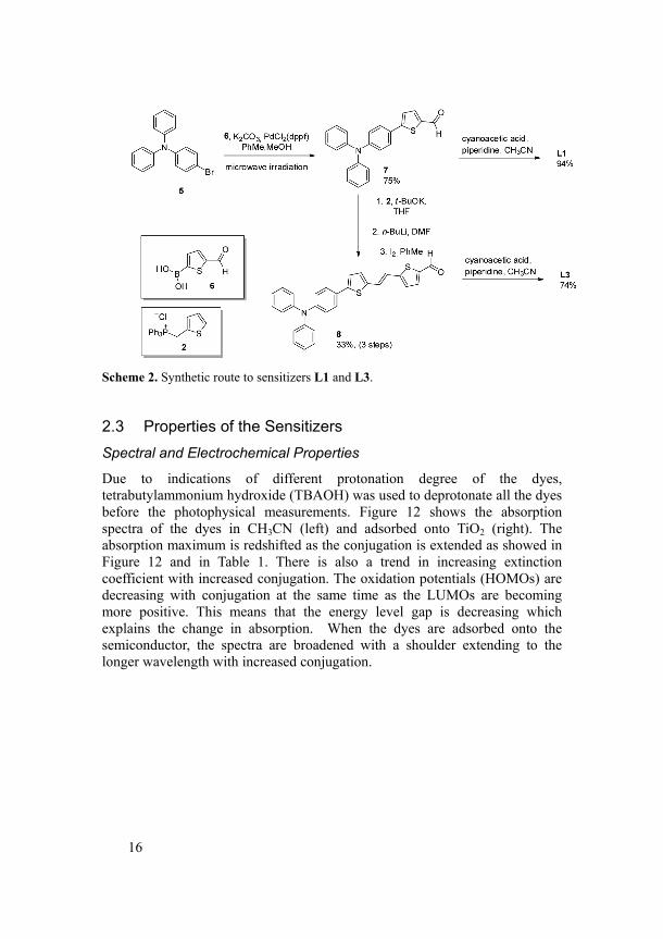
Triphenylamine (sometimes called diphenylaniline) can be obtained commercially as it is, or derivatized in different ways which makes it a good starting material for further development. In this series, two different starting compounds were used for the different dyes: A formylated TPA (1, Scheme 1) and the brominated analogue 5 as shown in Scheme 2. For the shortest sensitizer only one reaction step was needed, a Knoevenagel condensation between the aldehyde and cyanoacetic acid. The reaction is catalyzed by piperidine and performed by refluxing in CH3CN. The same conditions were used for all the dyes. A Wittig reaction with phosphonium salt 2 was used to create the double bond between the TPA and the thiophene in dye L2 and L4. This was immediately followed by formylation in the 5-position of the thiophene by n-BuLi and DMF. The formation of a mixture of both isomers made an additional step necessary; cis-to-trans isomerization was accomplished by refluxing the product in toluene in the presence of a catalytic amount of iodine.59 For the largest dye L4 this three step procedure was repeated once again to yield the aldehyde 4. The synthesis of L1 and L3 started with a Suzuki reaction with 5-formyl-2-thiophene boronic acid (6) and the brominated TPA 5. 1,1'-Bis(diphenylphosphino)ferrocene palladium(II) dichloride (PdCl2(dppf)) was used as catalyst and K2CO3 the base. The Suzuki reactions were performed under microwave irradiation and needed only 10 min at 70 °C. The following reactions were performed in a similar manner as for the former dyes.
Scheme 1. Synthesis of sensitizers L0, L2 and L4.
16
Scheme 2. Synthetic route to sensitizers L1 and L3.
2.3 Properties of the Sensitizers Spectral and Electrochemical Properties
Due to indications of different protonation degree of the dyes, tetrabutylammonium hydroxide (TBAOH) was used to deprotonate all the dyes before the photophysical measurements. Figure 12 shows the absorption spectra of the dyes in CH3CN (left) and adsorbed onto TiO2 (right). The absorption maximum is redshifted as the conjugation is extended as showed in Figure 12 and in Table 1. There is also a trend in increasing extinction coefficient with increased conjugation. The oxidation potentials (HOMOs) are decreasing with conjugation at the same time as the LUMOs are becoming more positive. This means that the energy level gap is decreasing which explains the change in absorption. When the dyes are adsorbed onto the semiconductor, the spectra are broadened with a shoulder extending to the longer wavelength with increased conjugation.
17
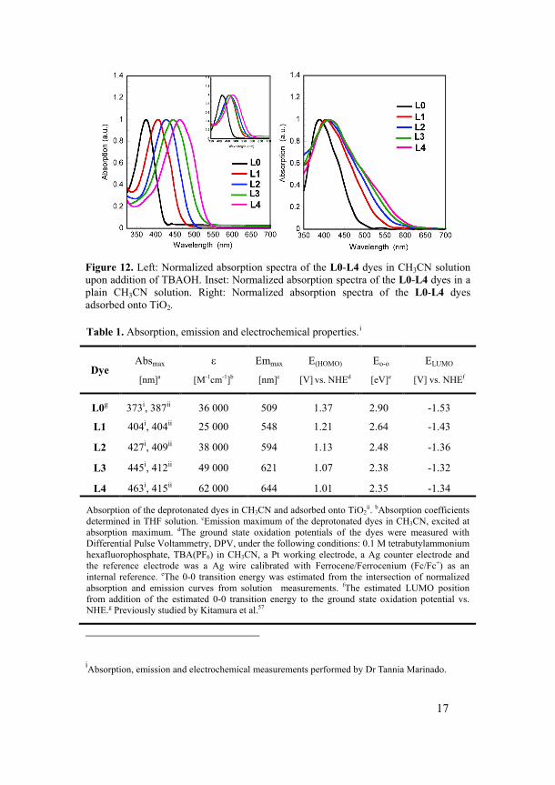
Figure 12. Left: Normalized absorption spectra of the L0-L4 dyes in CH3CN solution upon addition of TBAOH. Inset: Normalized absorption spectra of the L0-L4 dyes in a plain CH3CN solution. Right: Normalized absorption spectra of the L0-L4 dyes adsorbed onto TiO2.
Table 1. Absorption, emission and electrochemical properties.i
Dye Absmax
[nm]a
ε
[M-1cm-1]b
Emmax
[nm]c
E(HOMO)
[V] vs. NHEd
Eo-o
[eV]e
ELUMO
[V] vs. NHEf
L0g 373i, 387ii 36 000 509 1.37 2.90 -1.53
L1 404i, 404ii 25 000 548 1.21 2.64 -1.43
L2 427i, 409ii 38 000 594 1.13 2.48 -1.36
L3 445i, 412ii 49 000 621 1.07 2.38 -1.32
L4 463i, 415ii 62 000 644 1.01 2.35 -1.34
Absorption of the deprotonated dyes in CH3CN and adsorbed onto TiO2ii. bAbsorption coefficients
determined in THF solution. cEmission maximum of the deprotonated dyes in CH3CN, excited at absorption maximum. dThe ground state oxidation potentials of the dyes were measured with Differential Pulse Voltammetry, DPV, under the following conditions: 0.1 M tetrabutylammonium hexafluorophosphate, TBA(PF6) in CH3CN, a Pt working electrode, a Ag counter electrode and the reference electrode was a Ag wire calibrated with Ferrocene/Ferrocenium (Fc/Fc+) as an internal reference. eThe 0-0 transition energy was estimated from the intersection of normalized absorption and emission curves from solution measurements. fThe estimated LUMO position from addition of the estimated 0-0 transition energy to the ground state oxidation potential vs. NHE.g Previously studied by Kitamura et al.57
iAbsorption, emission and electrochemical measurements performed by Dr Tannia Marinado.
18
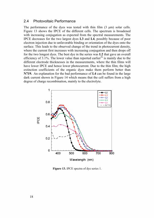
2.4 Photovoltaic Performance The performance of the dyes was tested with thin film (3 μm) solar cells. Figure 13 shows the IPCE of the different cells. The spectrum is broadened with increasing conjugation as expected from the spectral measurements. The IPCE decreases for the two largest dyes L3 and L4, possibly because of poor electron injection due to unfavorable binding or orientation of the dyes onto the surface. This leads to the observed change of the trend in photocurrent density, where the current first increases with increasing conjugation and then drops off for the two longest dyes. The best dye in the series was L2 that gave an overall efficiency of 3.1%. The lower value than reported earlier56 is mainly due to the different electrode thicknesses in the measurements, where the thin films will have lower IPCE and hence lower photocurrent. Due to the thin film; the high extinction coefficients of the organic dyes make them perform better than N719. An explanation for the bad performance of L4 can be found in the large dark current shown in Figure 14 which means that the cell suffers from a high degree of charge recombination, mainly to the electrolyte.
Figure 13. IPCE spectra of dye series 1.
19
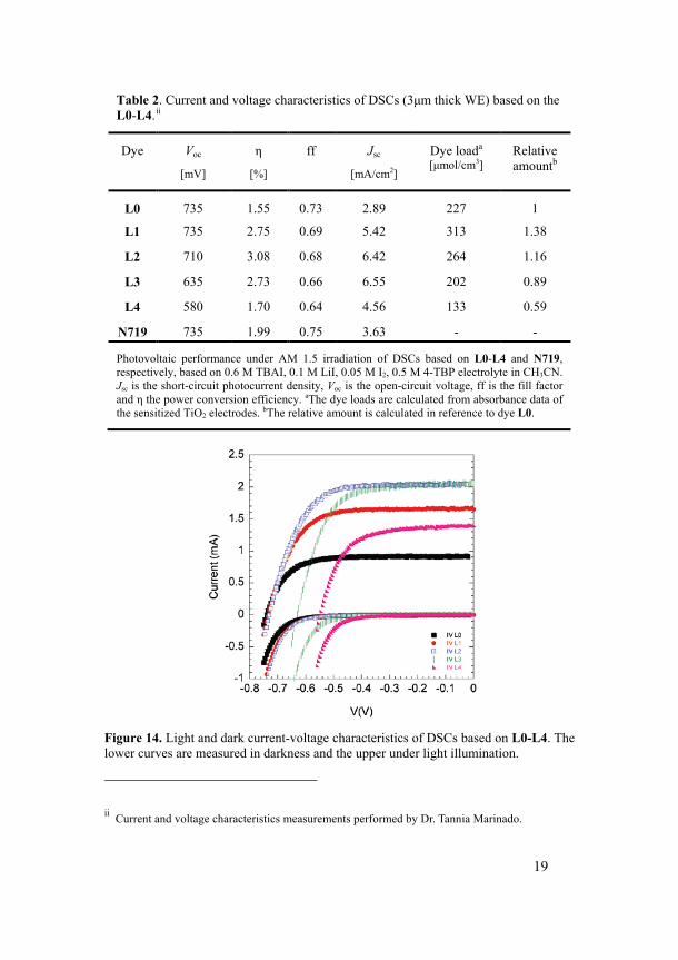
Table 2. Current and voltage characteristics of DSCs (3μm thick WE) based on the L0-L4.ii
Dye Voc
[mV]
η
[%]
ff Jsc
[mA/cm2]
Dye loada [μmol/cm3]
Relative amountb
L0 735 1.55 0.73 2.89 227 1
L1 735 2.75 0.69 5.42 313 1.38
L2 710 3.08 0.68 6.42 264 1.16
L3 635 2.73 0.66 6.55 202 0.89
L4 580 1.70 0.64 4.56 133 0.59
N719 735 1.99 0.75 3.63 - -
Photovoltaic performance under AM 1.5 irradiation of DSCs based on L0-L4 and N719, respectively, based on 0.6 M TBAI, 0.1 M LiI, 0.05 M I2, 0.5 M 4-TBP electrolyte in CH3CN. Jsc is the short-circuit photocurrent density, Voc is the open-circuit voltage, ff is the fill factor and η the power conversion efficiency. aThe dye loads are calculated from absorbance data of the sensitized TiO2 electrodes. bThe relative amount is calculated in reference to dye L0.
Figure 14. Light and dark current-voltage characteristics of DSCs based on L0-L4. The lower curves are measured in darkness and the upper under light illumination.
ii Current and voltage characteristics measurements performed by Dr. Tannia Marinado.
20
2.5 Conclusions Changing the degree of conjugation in the sensitizer is a convenient way of tuning the energy levels. The extension will change both the HOMO and the LUMO to give a smaller gap between them thus shifting the absorption into longer wavelengths. This can result in improved photocurrents of the solar cell. With longer dye structures unfavorable losses such as electron recombination increases, due to decreased surface protection.
21
3 Adding a Second TPA Moiety (Paper II)
3.1 Introduction One important feature of dyes for DSC applications is that the excitation should be associated with vectorial electron flow from the light harvesting moiety towards the surface of the semiconductor. This is accomplished by the use of the D-π-A strategy. The previous chapter described the strategy of tuning the energy levels of the sensitizer by changing the conjugation. By the individual change of one of the different parts at a time one can probe the influence of the alteration in order to get more insight into the properties necessary for good performance of the sensitizer in the solar cell. By increasing the electron donating properties of the donor moiety a bathochromic shift can be achieved and thus increase the photocurrent in the solar cell. Another important factor for high performance of the solar cells is the depression of dye aggregation on the semiconductor surface and electron recombination with the oxidized dye or electrolyte.60,61 A common strategy to treat this issue is by adding insulating alkyl chains to the dye structure.24,35 An alternative is to use bulky groups in order to protect the surface from interacting with the redox couple in the electrolyte and also decrease dye aggregation.62 To improve the long term stability of the devices the volatile electrolyte can be exchanged for a solid state hole-conductor such as spiro-OMeTAD (Figure 4).
Aim of the study
This chapter deals with the variation of different electron donating moieties in TPA based sensitizers. An additional bulky TPA donor is introduced and the change of the electron donating properties of the TPA is accomplished by the introduction of methoxy substituents. The dyes were evaluated as sensitizers in both liquid cells and in solid state DSCs (ssDSCs).
22
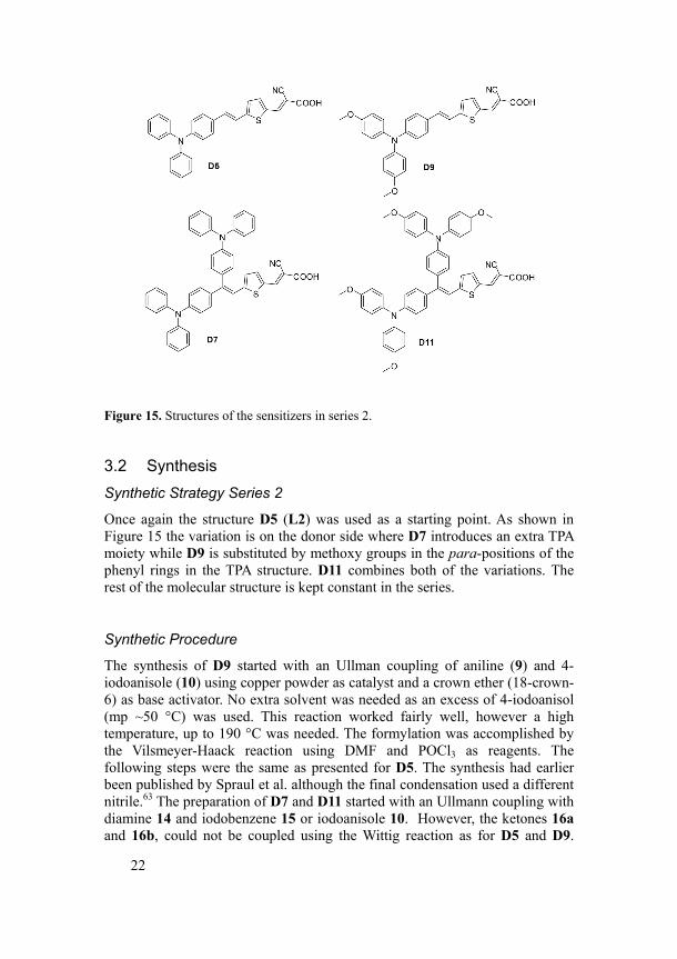
Figure 15. Structures of the sensitizers in series 2.
3.2 Synthesis Synthetic Strategy Series 2
Once again the structure D5 (L2) was used as a starting point. As shown in Figure 15 the variation is on the donor side where D7 introduces an extra TPA moiety while D9 is substituted by methoxy groups in the para-positions of the phenyl rings in the TPA structure. D11 combines both of the variations. The rest of the molecular structure is kept constant in the series.
Synthetic Procedure
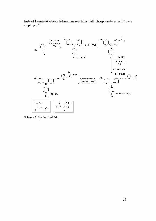
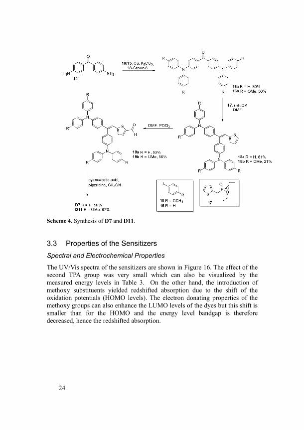
The synthesis of D9 started with an Ullman coupling of aniline (9) and 4-iodoanisole (10) using copper powder as catalyst and a crown ether (18-crown-6) as base activator. No extra solvent was needed as an excess of 4-iodoanisol (mp ~50 °C) was used. This reaction worked fairly well, however a high temperature, up to 190 °C was needed. The formylation was accomplished by the Vilsmeyer-Haack reaction using DMF and POCl3 as reagents. The following steps were the same as presented for D5. The synthesis had earlier been published by Spraul et al. although the final condensation used a different nitrile.63 The preparation of D7 and D11 started with an Ullmann coupling with diamine 14 and iodobenzene 15 or iodoanisole 10. However, the ketones 16a and 16b, could not be coupled using the Wittig reaction as for D5 and D9.
23
Instead Horner-Wadsworth-Emmons reactions with phosphonate ester 17 were employed.64
Scheme 3. Synthesis of D9.
24
Scheme 4. Synthesis of D7 and D11.
3.3 Properties of the Sensitizers Spectral and Electrochemical Properties
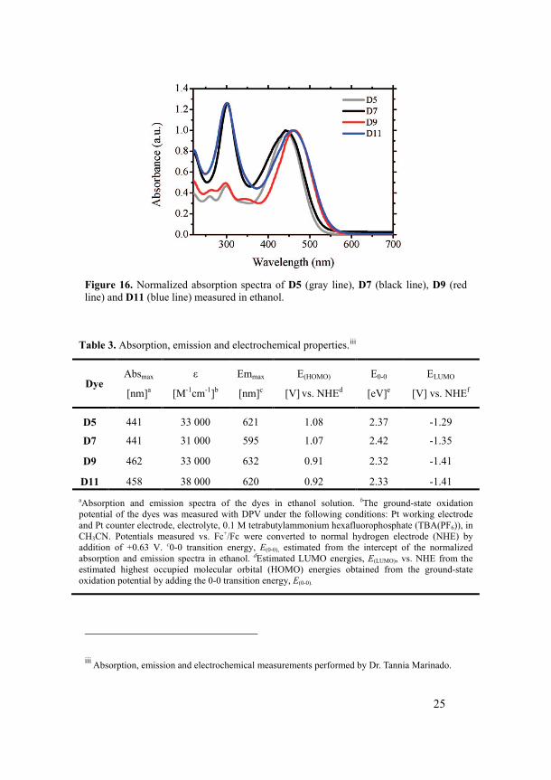
The UV/Vis spectra of the sensitizers are shown in Figure 16. The effect of the second TPA group was very small which can also be visualized by the measured energy levels in Table 3. On the other hand, the introduction of methoxy substituents yielded redshifted absorption due to the shift of the oxidation potentials (HOMO levels). The electron donating properties of the methoxy groups can also enhance the LUMO levels of the dyes but this shift is smaller than for the HOMO and the energy level bandgap is therefore decreased, hence the redshifted absorption.
25
Figure 16. Normalized absorption spectra of D5 (gray line), D7 (black line), D9 (red line) and D11 (blue line) measured in ethanol.
Table 3. Absorption, emission and electrochemical properties.iii
Dye Absmax
[nm]a
ε
[M-1cm-1]b
Emmax
[nm]c
E(HOMO)
[V] vs. NHEd
E0-0
[eV]e
ELUMO
[V] vs. NHEf
D5 441 33 000 621 1.08 2.37 -1.29
D7 441 31 000 595 1.07 2.42 -1.35
D9 462 33 000 632 0.91 2.32 -1.41
D11 458 38 000 620 0.92 2.33 -1.41 aAbsorption and emission spectra of the dyes in ethanol solution. bThe ground-state oxidation potential of the dyes was measured with DPV under the following conditions: Pt working electrode and Pt counter electrode, electrolyte, 0.1 M tetrabutylammonium hexafluorophosphate (TBA(PF6)), in CH3CN. Potentials measured vs. Fc+/Fc were converted to normal hydrogen electrode (NHE) by addition of +0.63 V. c0-0 transition energy, E(0-0), estimated from the intercept of the normalized absorption and emission spectra in ethanol. dEstimated LUMO energies, E(LUMO), vs. NHE from the estimated highest occupied molecular orbital (HOMO) energies obtained from the ground-state oxidation potential by adding the 0-0 transition energy, E(0-0).
iii Absorption, emission and electrochemical measurements performed by Dr. Tannia Marinado.
26
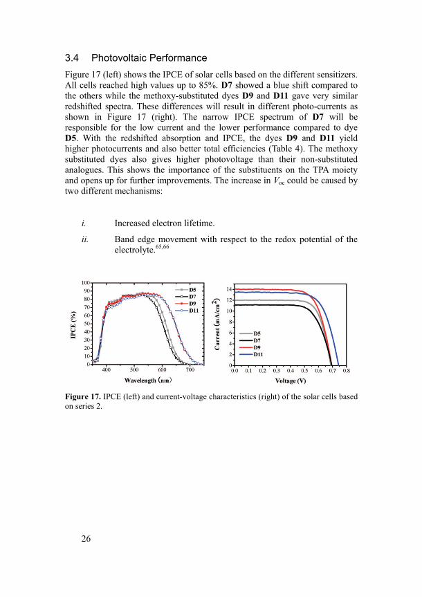
3.4 Photovoltaic Performance Figure 17 (left) shows the IPCE of solar cells based on the different sensitizers. All cells reached high values up to 85%. D7 showed a blue shift compared to the others while the methoxy-substituted dyes D9 and D11 gave very similar redshifted spectra. These differences will result in different photo-currents as shown in Figure 17 (right). The narrow IPCE spectrum of D7 will be responsible for the low current and the lower performance compared to dye D5. With the redshifted absorption and IPCE, the dyes D9 and D11 yield higher photocurrents and also better total efficiencies (Table 4). The methoxy substituted dyes also gives higher photovoltage than their non-substituted analogues. This shows the importance of the substituents on the TPA moiety and opens up for further improvements. The increase in Voc could be caused by two different mechanisms:
i. Increased electron lifetime.
ii. Band edge movement with respect to the redox potential of the electrolyte.65,66
Figure 17. IPCE (left) and current-voltage characteristics (right) of the solar cells based on series 2.
27
Table 4. Photovoltaic performance of DSCs based on the different dyes. iv
Dye Jsc (mA/cm2) Voc (V) FF η (%)
D5 12.00 0.688 0.72 5.94
D7 11.00 0.695 0.71 5.43
D9 14.00 0.694 0.71 6.90
D11 13.50 0.744 0.70 7.03
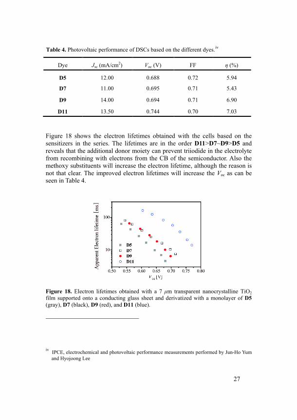
Figure 18 shows the electron lifetimes obtained with the cells based on the sensitizers in the series. The lifetimes are in the order D11>D7~D9>D5 and reveals that the additional donor moiety can prevent triiodide in the electrolyte from recombining with electrons from the CB of the semiconductor. Also the methoxy substituents will increase the electron lifetime, although the reason is not that clear. The improved electron lifetimes will increase the Voc as can be seen in Table 4.
Figure 18. Electron lifetimes obtained with a 7 μm transparent nanocrystalline TiO2 film supported onto a conducting glass sheet and derivatized with a monolayer of D5 (gray), D7 (black), D9 (red), and D11 (blue).
iv IPCE, electrochemical and photovoltaic performance measurements performed by Jun-Ho Yum and Hyojoong Lee
28
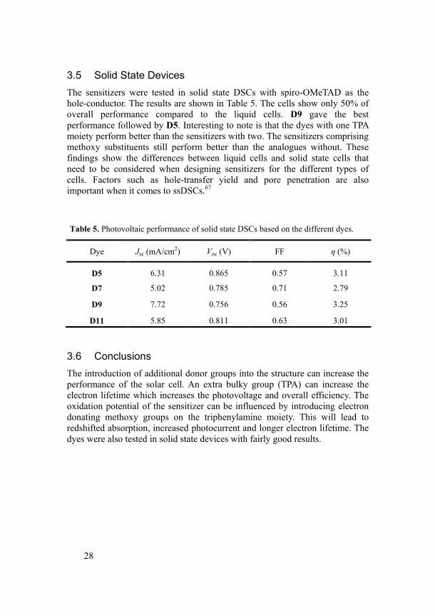
3.5 Solid State Devices The sensitizers were tested in solid state DSCs with spiro-OMeTAD as the hole-conductor. The results are shown in Table 5. The cells show only 50% of overall performance compared to the liquid cells. D9 gave the best performance followed by D5. Interesting to note is that the dyes with one TPA moiety perform better than the sensitizers with two. The sensitizers comprising methoxy substituents still perform better than the analogues without. These findings show the differences between liquid cells and solid state cells that need to be considered when designing sensitizers for the different types of cells. Factors such as hole-transfer yield and pore penetration are also important when it comes to ssDSCs.67
Table 5. Photovoltaic performance of solid state DSCs based on the different dyes.
Dye Jsc (mA/cm2) Voc (V) FF η (%)
D5 6.31 0.865 0.57 3.11
D7 5.02 0.785 0.71 2.79
D9 7.72 0.756 0.56 3.25
D11 5.85 0.811 0.63 3.01
3.6 Conclusions The introduction of additional donor groups into the structure can increase the performance of the solar cell. An extra bulky group (TPA) can increase the electron lifetime which increases the photovoltage and overall efficiency. The oxidation potential of the sensitizer can be influenced by introducing electron donating methoxy groups on the triphenylamine moiety. This will lead to redshifted absorption, increased photocurrent and longer electron lifetime. The dyes were also tested in solid state devices with fairly good results.
29
4 Further Donor Variation for Efficient Solid State DSCs
(Paper III)
4.1 Introduction The previous chapter ended with the test of the dyes in solid state solar cell application which is an important development of the DSC in which the liquid electrolyte has been replaced by a solid state hole-conductor such as spiro-OMeTAD. The solar energy to electricity conversion efficiencies obtained were however only 50% of that for the liquid cells. To improve the performance, changes to the molecular structure of the sensitizers need to be done. Extension of the conjugation using a double bond has the drawback of possible photo-isomerization that can influence the stability of the cell.58 This problem can be avoided by substituting the double bond with a heterocyclic linker. The introduction of alkyl chains in the structure has earlier shown to improve the performance of the solar cells due to a better surface protection which will increase the electron lifetime.39 However; it is important that the alkyl chains are placed in the right positions of the dye structure. There are examples of decreased performance when utilizing alkyl chains as well.68 Alkyl chains in the middle of the molecule can force the molecule to twist, which can lead to a less efficient orbital overlap and decreased light absorption. Putting the chains on the donor will increase the distance to the surface but if the chains are long enough and the sensitizer is not too long this could be a better approach.
Aim of the Study
Chapter 4 describes the performance of solid state DSCs using a new series of organic sensitizers. The donor is further modified by the introduction of alkoxygroups with different chain lengths and the previously used double bond is replaced by a second thiophene.
30
4.2 Synthesis Synthetic Strategy
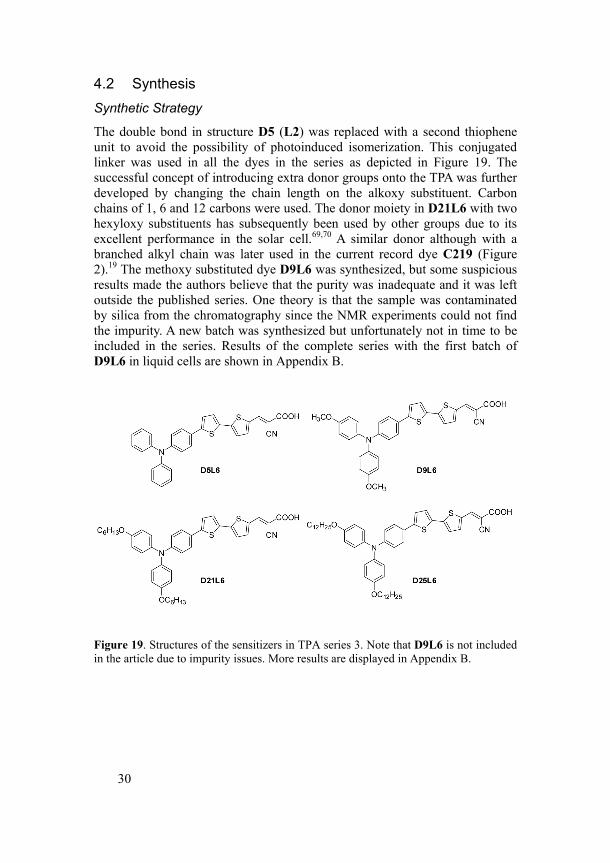
The double bond in structure D5 (L2) was replaced with a second thiophene unit to avoid the possibility of photoinduced isomerization. This conjugated linker was used in all the dyes in the series as depicted in Figure 19. The successful concept of introducing extra donor groups onto the TPA was further developed by changing the chain length on the alkoxy substituent. Carbon chains of 1, 6 and 12 carbons were used. The donor moiety in D21L6 with two hexyloxy substituents has subsequently been used by other groups due to its excellent performance in the solar cell.69,70 A similar donor although with a branched alkyl chain was later used in the current record dye C219 (Figure 2).19 The methoxy substituted dye D9L6 was synthesized, but some suspicious results made the authors believe that the purity was inadequate and it was left outside the published series. One theory is that the sample was contaminated by silica from the chromatography since the NMR experiments could not find the impurity. A new batch was synthesized but unfortunately not in time to be included in the series. Results of the complete series with the first batch of D9L6 in liquid cells are shown in Appendix B.
Figure 19. Structures of the sensitizers in TPA series 3. Note that D9L6 is not included in the article due to impurity issues. More results are displayed in Appendix B.
31
Synthetic Procedure
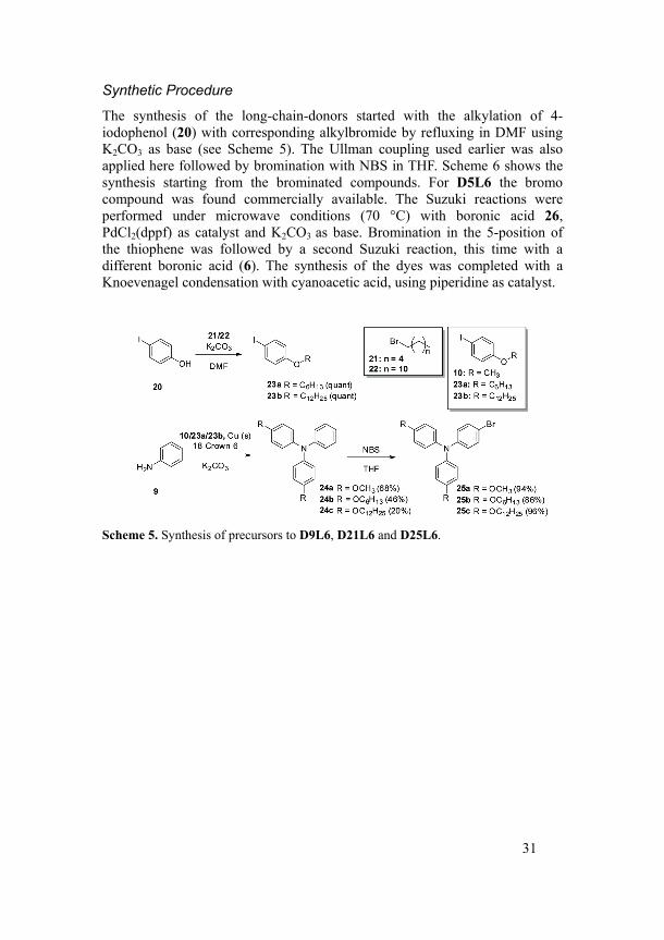
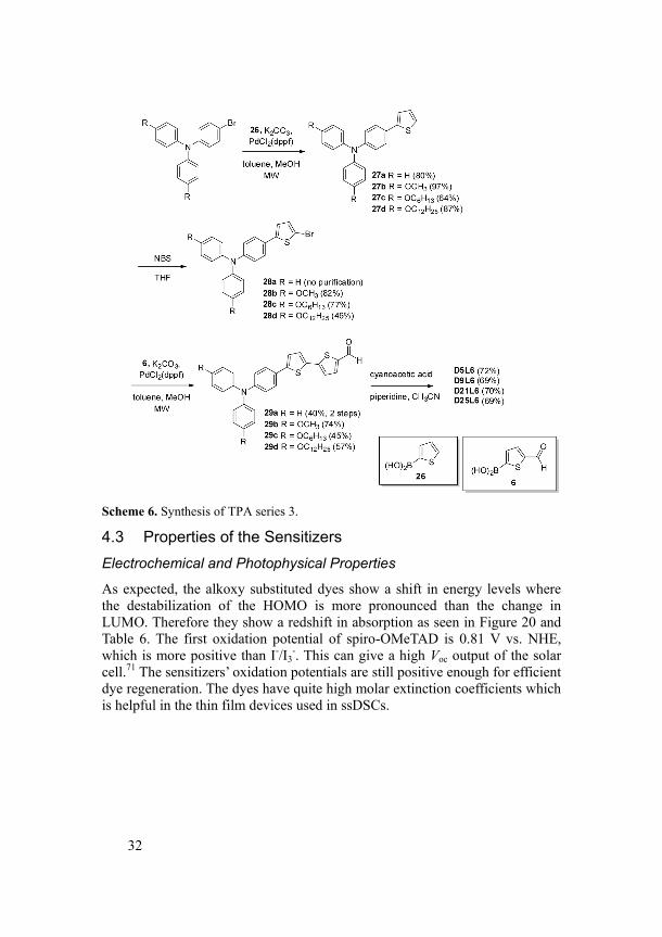
The synthesis of the long-chain-donors started with the alkylation of 4-iodophenol (20) with corresponding alkylbromide by refluxing in DMF using K2CO3 as base (see Scheme 5). The Ullman coupling used earlier was also applied here followed by bromination with NBS in THF. Scheme 6 shows the synthesis starting from the brominated compounds. For D5L6 the bromo compound was found commercially available. The Suzuki reactions were performed under microwave conditions (70 °C) with boronic acid 26, PdCl2(dppf) as catalyst and K2CO3 as base. Bromination in the 5-position of the thiophene was followed by a second Suzuki reaction, this time with a different boronic acid (6). The synthesis of the dyes was completed with a Knoevenagel condensation with cyanoacetic acid, using piperidine as catalyst.
Scheme 5. Synthesis of precursors to D9L6, D21L6 and D25L6.
32
Scheme 6. Synthesis of TPA series 3.
4.3 Properties of the Sensitizers Electrochemical and Photophysical Properties
As expected, the alkoxy substituted dyes show a shift in energy levels where the destabilization of the HOMO is more pronounced than the change in LUMO. Therefore they show a redshift in absorption as seen in Figure 20 and Table 6. The first oxidation potential of spiro-OMeTAD is 0.81 V vs. NHE, which is more positive than I-/I3
-. This can give a high Voc output of the solar cell.71 The sensitizers’ oxidation potentials are still positive enough for efficient dye regeneration. The dyes have quite high molar extinction coefficients which is helpful in the thin film devices used in ssDSCs.
33
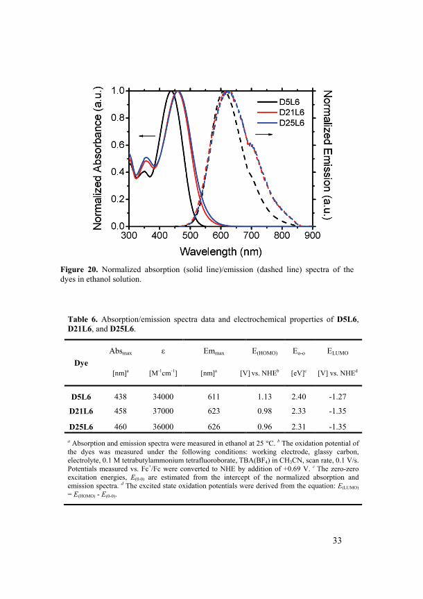
Table 6. Absorption/emission spectra data and electrochemical properties of D5L6, D21L6, and D25L6.
Dye Absmax ε Emmax E(HOMO) Eo-o ELUMO
[nm]a [M-1cm-1] [nm]a [V] vs. NHEb [eV]c [V] vs. NHEd
D5L6 438 34000 611 1.13 2.40 -1.27
D21L6 458 37000 623 0.98 2.33 -1.35
D25L6 460 36000 626 0.96 2.31 -1.35 a Absorption and emission spectra were measured in ethanol at 25 °C. b The oxidation potential of the dyes was measured under the following conditions: working electrode, glassy carbon, electrolyte, 0.1 M tetrabutylammonium tetrafluoroborate, TBA(BF4) in CH3CN, scan rate, 0.1 V/s. Potentials measured vs. Fc+/Fc were converted to NHE by addition of +0.69 V. c The zero-zero excitation energies, E(0-0) are estimated from the intercept of the normalized absorption and emission spectra. d The excited state oxidation potentials were derived from the equation: E(LUMO) = E(HOMO) - E(0-0).
Figure 20. Normalized absorption (solid line)/emission (dashed line) spectra of the dyes in ethanol solution.
34
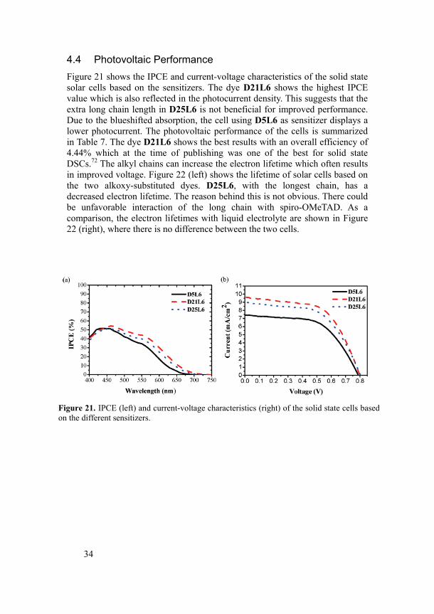
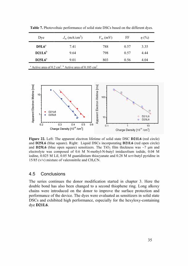
4.4 Photovoltaic Performance Figure 21 shows the IPCE and current-voltage characteristics of the solid state solar cells based on the sensitizers. The dye D21L6 shows the highest IPCE value which is also reflected in the photocurrent density. This suggests that the extra long chain length in D25L6 is not beneficial for improved performance. Due to the blueshifted absorption, the cell using D5L6 as sensitizer displays a lower photocurrent. The photovoltaic performance of the cells is summarized in Table 7. The dye D21L6 shows the best results with an overall efficiency of 4.44% which at the time of publishing was one of the best for solid state DSCs.72 The alkyl chains can increase the electron lifetime which often results in improved voltage. Figure 22 (left) shows the lifetime of solar cells based on the two alkoxy-substituted dyes. D25L6, with the longest chain, has a decreased electron lifetime. The reason behind this is not obvious. There could be unfavorable interaction of the long chain with spiro-OMeTAD. As a comparison, the electron lifetimes with liquid electrolyte are shown in Figure 22 (right), where there is no difference between the two cells.
Figure 21. IPCE (left) and current-voltage characteristics (right) of the solid state cells based on the different sensitizers.
35
Table 7. Photovoltaic performance of solid state DSCs based on the different dyes.
Dye Jsc (mA/cm2) Voc (mV) FF η (%)
D5L6a 7.41 788 0.57 3.35
D21L6b 9.64 798 0.57 4.44
D25L6a 9.01 803 0.56 4.04 a Active area of 0.2 cm2. b Active area of 0.185 cm2.
Figure 22. Left: The apparent electron lifetime of solid state DSC D21L6 (red circle) and D25L6 (blue square). Right: Liquid DSCs incorporating D21L6 (red open circle) and D25L6 (blue open square) sensitizers. The TiO2 film thickness was ~7 μm and electrolyte was composed of 0.6 M N-methyl-N-butyl imidazolium iodide, 0.04 M iodine, 0.025 M LiI, 0.05 M guanidinium thiocyanate and 0.28 M tert-butyl pyridine in 15/85 (v/v) mixture of valeronitrile and CH3CN.
4.5 Conclusions The series continues the donor modification started in chapter 3. Here the double bond has also been changed to a second thiophene ring. Long alkoxy chains were introduced on the donor to improve the surface protection and performance of the device. The dyes were evaluated as sensitizers in solid state DSCs and exhibited high performance, especially for the hexyloxy-containing dye D21L6.
36
5 Two Anchor/Acceptor Groups in the Structure
(Paper IV)
5.1 Introduction
Most organic sensitizers for DSCs are made with the D-π-A structure as the sensitizers in the previous chapters. A difference compared to some of the Ru-based sensitizers is the number of anchoring groups that can adsorb to the semiconductor surface. For example, it has been shown that two of the carboxylic acid groups on N719 bind to the TiO2.73 This can have some influence on the long term stability of the devices due to desorption of the sensitizer. In 2009, Abbotto and co-workers published a study on what they called di-branched di-anchoring organic dyes for DSCs.74 It was a TPA based structure with two acceptor/anchoring groups instead of one. This example was one of the first studies of organic dyes with more than one acceptor/anchoring group and it was shown that both carboxylic acid groups could bind to the semiconductor surface. A few other examples of sensitizers with more than one acceptor/anchoring group for DSC application have also been reported.75-79 Some advantages of having an additional acceptor arm are the enhanced absorption due to the extended π-conjugation and the ability to have multi-bonding to the semiconductor nano-particles.74
Many different conjugated linkers are known, among them different aromatic compounds or vinylene units. The currently most common linkers are thiophenes and their derivaties,58,80 but also furan, pyrrole and other heterocycles have been shown to work well as the linker for DSC applications.70,74,81,82 Earlier chapters show that adding electron donating substituents at the para positions on the triphenylamine unit will yield a redshifted absorption. By combining this donating property with insulating alkyl chains, the stability and the photovoltaic performance of the dyes may be increased.72,83 With two arms of the dye molecule in close contact with the semiconductor surface there is a possibility to get a more protected surface which can result in decreased dark current and an improved open circuit voltage with less need for the insulating alkyl chain. To investigate this further, a series of dyes with either a short or a long alkoxy chain as the substituent on the donor part and furan or thiophene as the conjugated linker in the chromophores were designed (Figure 23).
37
Aim of the Study
This part of our study deals with sensitizers containing two acceptors/anchor groups, their properties and how they perform in solar cells. If the additional arm can protect the surface, there might be no need for the long alkyl chains used in earlier systems. Photoelectron spectroscopy was used to determine the geometry of the dyes on the surface and to see whether both or only one of the anchor groups were linked to the surface. Also the difference between furan and thiophene as conjugated linkers was investigated. Density functional theory (DFT) and time-dependent DFT (TDDFT) calculations were performed in order to estimate the energy levels and spectral properties of the sensitizers prior to the synthesis.
5.2 Synthesis Synthetic Strategy
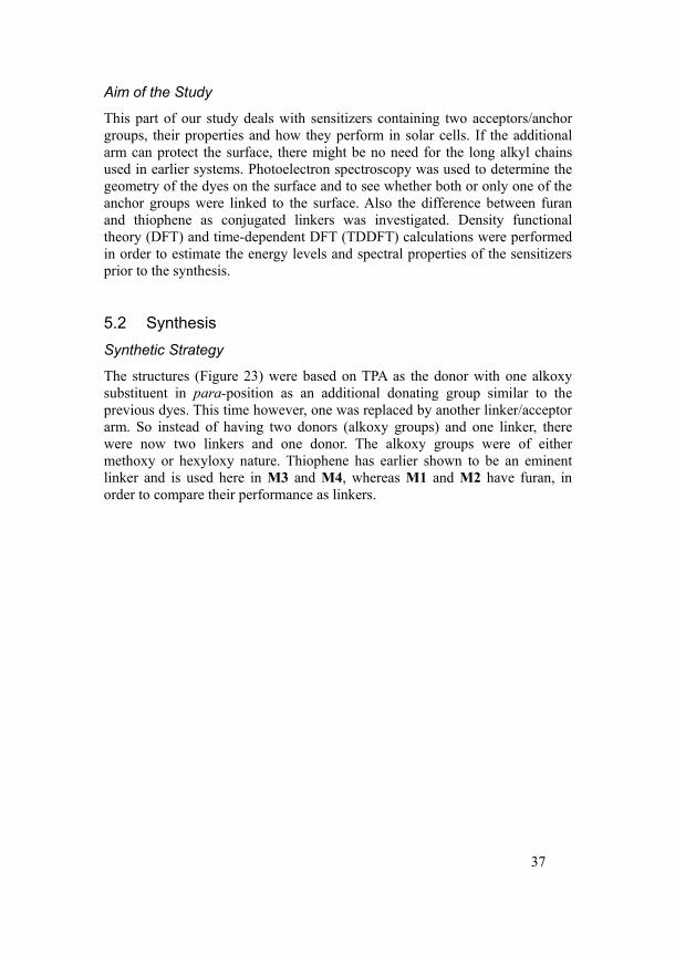
The structures (Figure 23) were based on TPA as the donor with one alkoxy substituent in para-position as an additional donating group similar to the previous dyes. This time however, one was replaced by another linker/acceptor arm. So instead of having two donors (alkoxy groups) and one linker, there were now two linkers and one donor. The alkoxy groups were of either methoxy or hexyloxy nature. Thiophene has earlier shown to be an eminent linker and is used here in M3 and M4, whereas M1 and M2 have furan, in order to compare their performance as linkers.
38
Figure 23. Structures of the sensitizers in series 4.
Synthetic Procedure
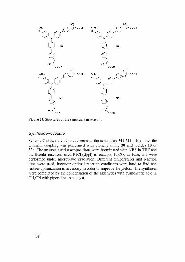
Scheme 7 shows the synthetic route to the sensitizers M1-M4. This time, the Ullmann coupling was performed with diphenylamine 30 and iodides 10 or 23a. The unsubstituted para-positions were brominated with NBS in THF and the Suzuki reactions used PdCl2(dppf) as catalyst, K2CO3 as base, and were performed under microwave irradiation. Different temperatures and reaction time were used, however optimal reaction conditions were hard to find and further optimization is necessary in order to improve the yields. The syntheses were completed by the condensation of the aldehydes with cyanoacetic acid in CH3CN with piperidine as catalyst.
39
Scheme 7. Synthesis of dye series 4.
5.3 Properties of the Sensitizers Calculated Propertiesv
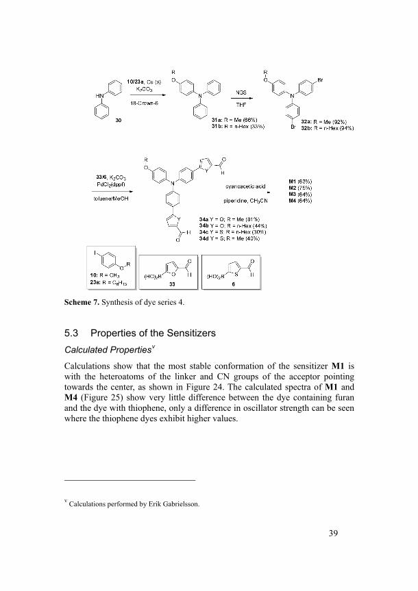
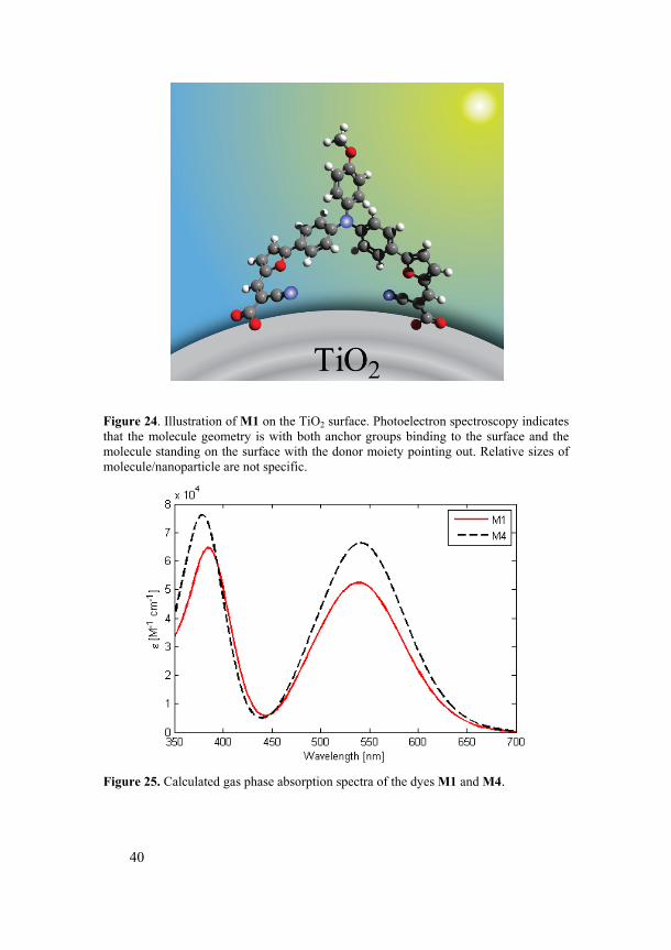
Calculations show that the most stable conformation of the sensitizer M1 is with the heteroatoms of the linker and CN groups of the acceptor pointing towards the center, as shown in Figure 24. The calculated spectra of M1 and M4 (Figure 25) show very little difference between the dye containing furan and the dye with thiophene, only a difference in oscillator strength can be seen where the thiophene dyes exhibit higher values.
v Calculations performed by Erik Gabrielsson.
40
Figure 24. Illustration of M1 on the TiO2 surface. Photoelectron spectroscopy indicates that the molecule geometry is with both anchor groups binding to the surface and the molecule standing on the surface with the donor moiety pointing out. Relative sizes of molecule/nanoparticle are not specific.
Figure 25. Calculated gas phase absorption spectra of the dyes M1 and M4.
41
Electrochemical and Photophysical Propertiesvi
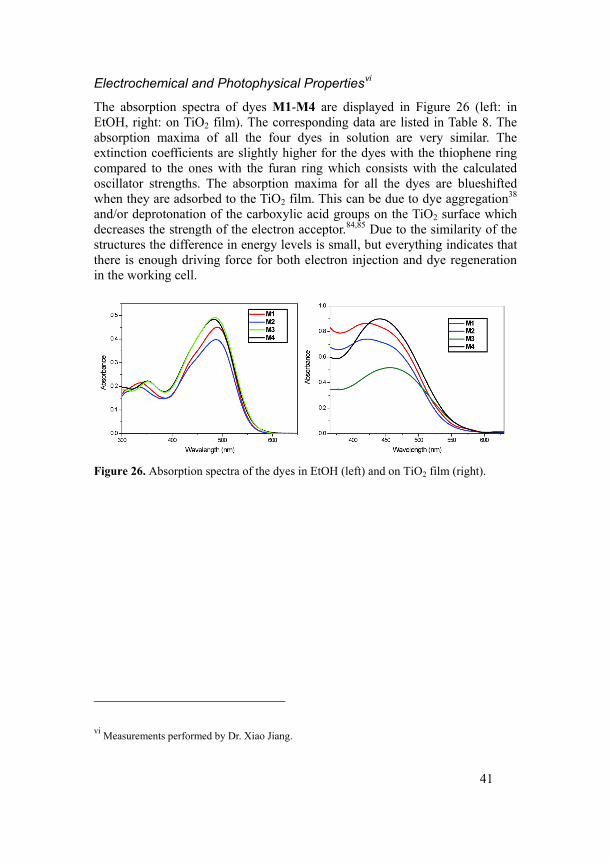
The absorption spectra of dyes M1-M4 are displayed in Figure 26 (left: in EtOH, right: on TiO2 film). The corresponding data are listed in Table 8. The absorption maxima of all the four dyes in solution are very similar. The extinction coefficients are slightly higher for the dyes with the thiophene ring compared to the ones with the furan ring which consists with the calculated oscillator strengths. The absorption maxima for all the dyes are blueshifted when they are adsorbed to the TiO2 film. This can be due to dye aggregation38 and/or deprotonation of the carboxylic acid groups on the TiO2 surface which decreases the strength of the electron acceptor.84,85 Due to the similarity of the structures the difference in energy levels is small, but everything indicates that there is enough driving force for both electron injection and dye regeneration in the working cell.
Figure 26. Absorption spectra of the dyes in EtOH (left) and on TiO2 film (right).
vi Measurements performed by Dr. Xiao Jiang.
42
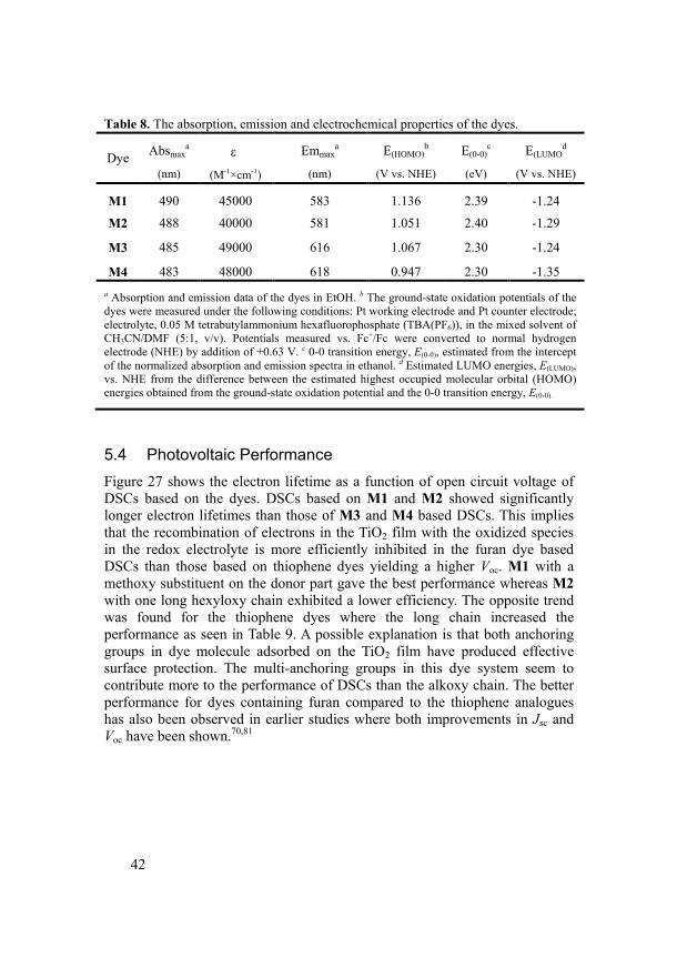
Table 8. The absorption, emission and electrochemical properties of the dyes.
Dye Absmax
a
(nm)
ε
(M-1×cm-1)
Emmaxa
(nm)
E(HOMO)b
(V vs. NHE)
E(0-0)c
(eV)
E(LUMOd
(V vs. NHE)
M1 490 45000 583 1.136 2.39 -1.24
M2 488 40000 581 1.051 2.40 -1.29
M3 485 49000 616 1.067 2.30 -1.24
M4 483 48000 618 0.947 2.30 -1.35 a Absorption and emission data of the dyes in EtOH. b The ground-state oxidation potentials of the dyes were measured under the following conditions: Pt working electrode and Pt counter electrode; electrolyte, 0.05 M tetrabutylammonium hexafluorophosphate (TBA(PF6)), in the mixed solvent of CH3CN/DMF (5:1, v/v). Potentials measured vs. Fc+/Fc were converted to normal hydrogen electrode (NHE) by addition of +0.63 V. c 0-0 transition energy, E(0-0), estimated from the intercept of the normalized absorption and emission spectra in ethanol. d Estimated LUMO energies, E(LUMO), vs. NHE from the difference between the estimated highest occupied molecular orbital (HOMO) energies obtained from the ground-state oxidation potential and the 0-0 transition energy, E(0-0).
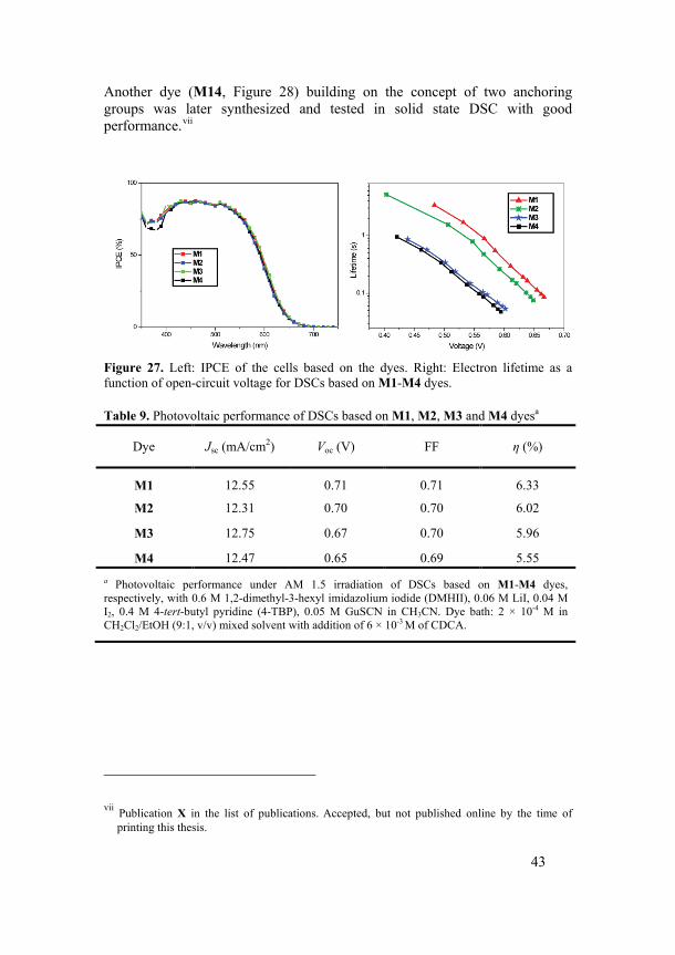
5.4 Photovoltaic Performance Figure 27 shows the electron lifetime as a function of open circuit voltage of DSCs based on the dyes. DSCs based on M1 and M2 showed significantly longer electron lifetimes than those of M3 and M4 based DSCs. This implies that the recombination of electrons in the TiO2 film with the oxidized species in the redox electrolyte is more efficiently inhibited in the furan dye based DSCs than those based on thiophene dyes yielding a higher Voc. M1 with a methoxy substituent on the donor part gave the best performance whereas M2 with one long hexyloxy chain exhibited a lower efficiency. The opposite trend was found for the thiophene dyes where the long chain increased the performance as seen in Table 9. A possible explanation is that both anchoring groups in dye molecule adsorbed on the TiO2 film have produced effective surface protection. The multi-anchoring groups in this dye system seem to contribute more to the performance of DSCs than the alkoxy chain. The better performance for dyes containing furan compared to the thiophene analogues has also been observed in earlier studies where both improvements in Jsc and Voc have been shown.70,81
43
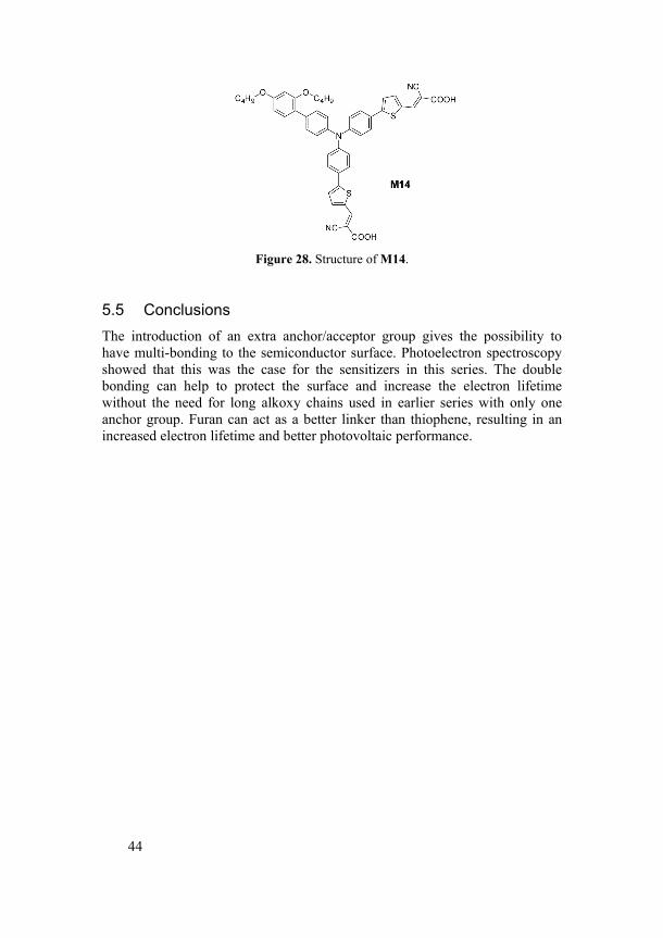
Another dye (M14, Figure 28) building on the concept of two anchoring groups was later synthesized and tested in solid state DSC with good performance.vii
Figure 27. Left: IPCE of the cells based on the dyes. Right: Electron lifetime as a function of open-circuit voltage for DSCs based on M1-M4 dyes.
Table 9. Photovoltaic performance of DSCs based on M1, M2, M3 and M4 dyesa
Dye Jsc (mA/cm2) Voc (V) FF η (%)
M1 12.55 0.71 0.71 6.33
M2 12.31 0.70 0.70 6.02
M3 12.75 0.67 0.70 5.96
M4 12.47 0.65 0.69 5.55 a Photovoltaic performance under AM 1.5 irradiation of DSCs based on M1-M4 dyes, respectively, with 0.6 M 1,2-dimethyl-3-hexyl imidazolium iodide (DMHII), 0.06 M LiI, 0.04 M I2, 0.4 M 4-tert-butyl pyridine (4-TBP), 0.05 M GuSCN in CH3CN. Dye bath: 2 × 10⁻⁴ M in CH2Cl2/EtOH (9:1, v/v) mixed solvent with addition of 6 × 10⁻³ M of CDCA.
vii Publication X in the list of publications. Accepted, but not published online by the time of printing this thesis.
44
Figure 28. Structure of M14.
5.5 Conclusions The introduction of an extra anchor/acceptor group gives the possibility to have multi-bonding to the semiconductor surface. Photoelectron spectroscopy showed that this was the case for the sensitizers in this series. The double bonding can help to protect the surface and increase the electron lifetime without the need for long alkoxy chains used in earlier series with only one anchor group. Furan can act as a better linker than thiophene, resulting in an increased electron lifetime and better photovoltaic performance.
45
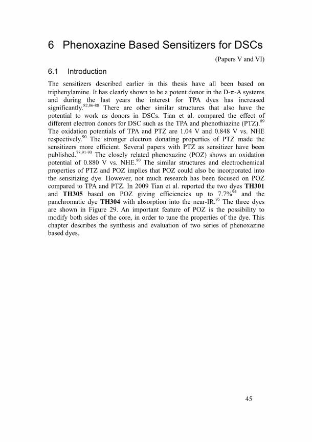
6 Phenoxazine Based Sensitizers for DSCs (Papers V and VI)
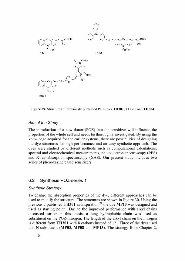
6.1 Introduction The sensitizers described earlier in this thesis have all been based on triphenylamine. It has clearly shown to be a potent donor in the D-π-A systems and during the last years the interest for TPA dyes has increased significantly.82,86-88 There are other similar structures that also have the potential to work as donors in DSCs. Tian et al. compared the effect of different electron donors for DSC such as the TPA and phenothiazine (PTZ).89 The oxidation potentials of TPA and PTZ are 1.04 V and 0.848 V vs. NHE respectively.90 The stronger electron donating properties of PTZ made the sensitizers more efficient. Several papers with PTZ as sensitizer have been published.78,91-93 The closely related phenoxazine (POZ) shows an oxidation potential of 0.880 V vs. NHE.90 The similar structures and electrochemical properties of PTZ and POZ implies that POZ could also be incorporated into the sensitizing dye. However, not much research has been focused on POZ compared to TPA and PTZ. In 2009 Tian et al. reported the two dyes TH301 and TH305 based on POZ giving efficiencies up to 7.7%94 and the panchromatic dye TH304 with absorption into the near-IR.95 The three dyes are shown in Figure 29. An important feature of POZ is the possibility to modify both sides of the core, in order to tune the properties of the dye. This chapter describes the synthesis and evaluation of two series of phenoxazine based dyes.
46
Figure 29. Structures of previously published POZ dyes TH301, TH305 and TH304.
Aim of the Study
The introduction of a new donor (POZ) into the sensitizer will influence the properties of the whole cell and needs be thoroughly investigated. By using the knowledge acquired for the earlier systems, there are possibilities of designing the dye structures for high performance and an easy synthetic approach. The dyes were studied by different methods such as computational calculations, spectral and electrochemical measurements, photoelectron spectroscopy (PES) and X-ray absorption spectroscopy (XAS). Our present study includes two series of phenoxazine based sensitizers.
6.2 Synthesis POZ-series 1
Synthetic Strategy
To change the absorption properties of the dye, different approaches can be used to modify the structure. The structures are shown in Figure 30. Using the previously published TH301 as inspiration,94 the dye MP13 was designed and used as starting point. Due to the improved performance with alkyl chains discussed earlier in this thesis, a long hydrophobic chain was used as substituent on the POZ-nitrogen. The length of the alkyl chain on the nitrogen is different from TH301 with 8 carbons instead of 12. Three of the dyes used this N-substituent (MP03, MP08 and MP13). The strategy from Chapter 2,
47
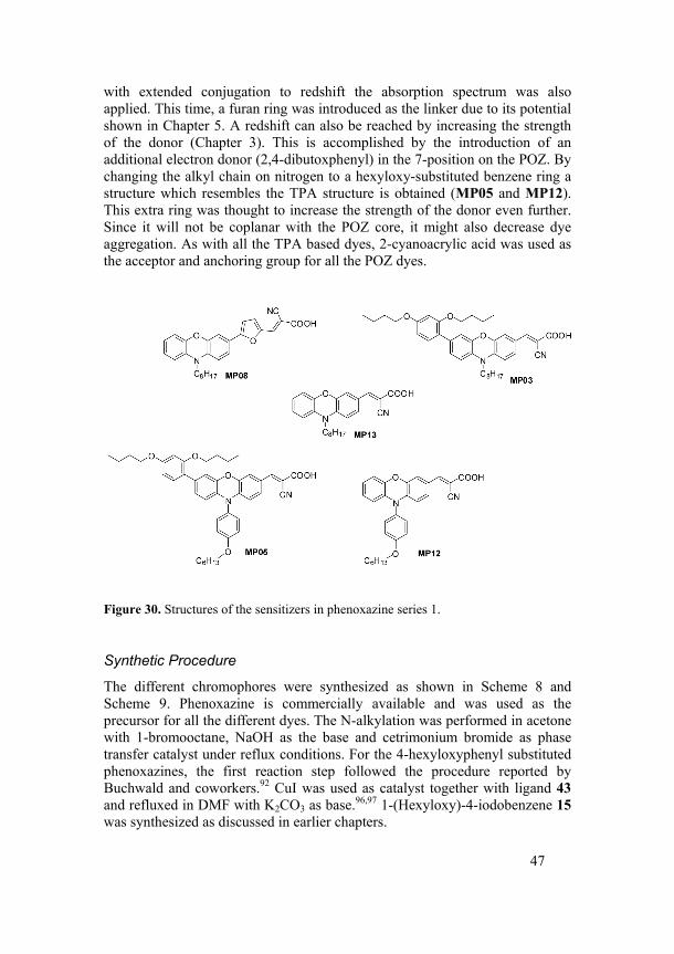
with extended conjugation to redshift the absorption spectrum was also applied. This time, a furan ring was introduced as the linker due to its potential shown in Chapter 5. A redshift can also be reached by increasing the strength of the donor (Chapter 3). This is accomplished by the introduction of an additional electron donor (2,4-dibutoxphenyl) in the 7-position on the POZ. By changing the alkyl chain on nitrogen to a hexyloxy-substituted benzene ring a structure which resembles the TPA structure is obtained (MP05 and MP12). This extra ring was thought to increase the strength of the donor even further. Since it will not be coplanar with the POZ core, it might also decrease dye aggregation. As with all the TPA based dyes, 2-cyanoacrylic acid was used as the acceptor and anchoring group for all the POZ dyes.
Figure 30. Structures of the sensitizers in phenoxazine series 1.
Synthetic Procedure
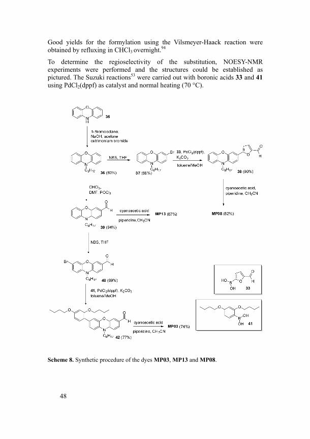
The different chromophores were synthesized as shown in Scheme 8 and Scheme 9. Phenoxazine is commercially available and was used as the precursor for all the different dyes. The N-alkylation was performed in acetone with 1-bromooctane, NaOH as the base and cetrimonium bromide as phase transfer catalyst under reflux conditions. For the 4-hexyloxyphenyl substituted phenoxazines, the first reaction step followed the procedure reported by Buchwald and coworkers.92 CuI was used as catalyst together with ligand 43 and refluxed in DMF with K2CO3 as base.96,97 1-(Hexyloxy)-4-iodobenzene 15 was synthesized as discussed in earlier chapters.
48
Good yields for the formylation using the Vilsmeyer-Haack reaction were obtained by refluxing in CHCl3 overnight.94
To determine the regioselectivity of the substitution, NOESY-NMR experiments were performed and the structures could be established as pictured. The Suzuki reactions53 were carried out with boronic acids 33 and 41 using PdCl2(dppf) as catalyst and normal heating (70 °C).
Scheme 8. Synthetic procedure of the dyes MP03, MP13 and MP08.
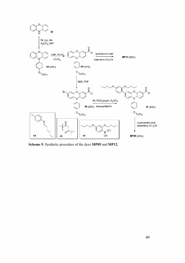
49
Scheme 9. Synthetic procedure of the dyes MP05 and MP12.
50
6.3 Properties of the Sensitizers Calculated Propertiesviii
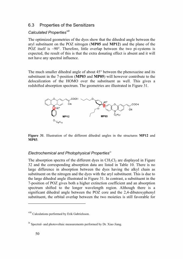
The optimized geometries of the dyes show that the dihedral angle between the aryl substituent on the POZ nitrogen (MP05 and MP12) and the plane of the POZ itself is ~90°. Therefore, little overlap between the two pi-systems is expected, the result of this is that the extra donating effect is absent and it will not have any spectral influence.
The much smaller dihedral angle of about 45° between the phenoxazine and its substituent in the 7-position (MP03 and MP05) will however contribute to the delocalization of the HOMO over the substituent as well. This gives a redshifted absorption spectrum. The geometries are illustrated in Figure 31.
Figure 31. Illustration of the different dihedral angles in the structures MP12 and MP03.
Electrochemical and Photophysical Propertiesix
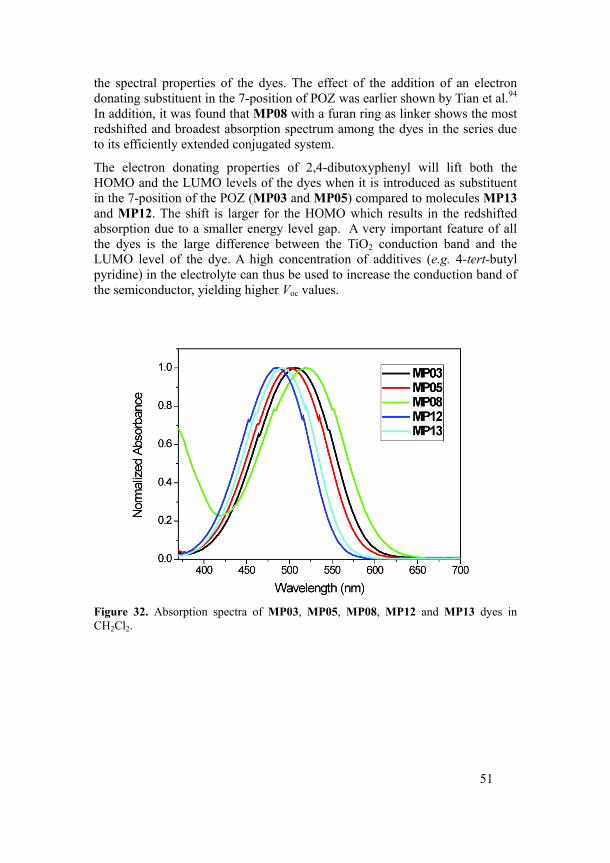
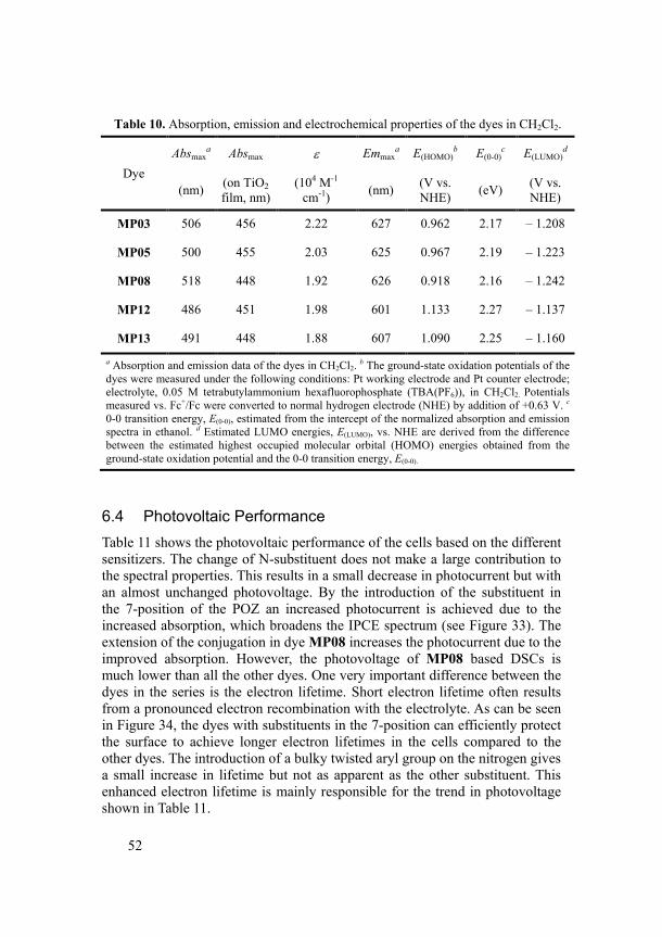
The absorption spectra of the different dyes in CH2Cl2 are displayed in Figure 32 and the corresponding absorption data are listed in Table 10. There is no large difference in absorption between the dyes having the alkyl chain as substituent on the nitrogen and the dyes with the aryl substituent. This is due to the large dihedral angle illustrated in Figure 31. In contrast, a substituent in the 7-position of POZ gives both a higher extinction coefficient and an absorption spectrum shifted to the longer wavelength region. Although there is a significant dihedral angle between the POZ core and the 2,4-dibutoxyphenyl substituent, the orbital overlap between the two moieties is still favorable for
viii Calculations performed by Erik Gabrielsson.
ix Spectral- and photovoltaic measurements performed by Dr. Xiao Jiang.
51
the spectral properties of the dyes. The effect of the addition of an electron donating substituent in the 7-position of POZ was earlier shown by Tian et al.94 In addition, it was found that MP08 with a furan ring as linker shows the most redshifted and broadest absorption spectrum among the dyes in the series due to its efficiently extended conjugated system.
The electron donating properties of 2,4-dibutoxyphenyl will lift both the HOMO and the LUMO levels of the dyes when it is introduced as substituent in the 7-position of the POZ (MP03 and MP05) compared to molecules MP13 and MP12. The shift is larger for the HOMO which results in the redshifted absorption due to a smaller energy level gap. A very important feature of all the dyes is the large difference between the TiO2 conduction band and the LUMO level of the dye. A high concentration of additives (e.g. 4-tert-butyl pyridine) in the electrolyte can thus be used to increase the conduction band of the semiconductor, yielding higher Voc values.
Figure 32. Absorption spectra of MP03, MP05, MP08, MP12 and MP13 dyes in CH2Cl2.
52
Table 10. Absorption, emission and electrochemical properties of the dyes in CH2Cl2.
Dye Absmax
a Absmax ε Emmaxa E(HOMO)
b E(0-0)c E(LUMO)
d
(nm) (on TiO2 film, nm)
(104 M-1 cm-1) (nm) (V vs.
NHE) (eV) (V vs. NHE)
MP03 506 456 2.22 627 0.962 2.17 – 1.208
MP05 500 455 2.03 625 0.967 2.19 – 1.223
MP08 518 448 1.92 626 0.918 2.16 – 1.242
MP12 486 451 1.98 601 1.133 2.27 – 1.137
MP13 491 448 1.88 607 1.090 2.25 – 1.160
a Absorption and emission data of the dyes in CH2Cl2. b The ground-state oxidation potentials of the dyes were measured under the following conditions: Pt working electrode and Pt counter electrode; electrolyte, 0.05 M tetrabutylammonium hexafluorophosphate (TBA(PF6)), in CH2Cl2. Potentials measured vs. Fc+/Fc were converted to normal hydrogen electrode (NHE) by addition of +0.63 V. c 0-0 transition energy, E(0-0), estimated from the intercept of the normalized absorption and emission spectra in ethanol. d Estimated LUMO energies, E(LUMO), vs. NHE are derived from the difference between the estimated highest occupied molecular orbital (HOMO) energies obtained from the ground-state oxidation potential and the 0-0 transition energy, E(0-0).
6.4 Photovoltaic Performance Table 11 shows the photovoltaic performance of the cells based on the different sensitizers. The change of N-substituent does not make a large contribution to the spectral properties. This results in a small decrease in photocurrent but with an almost unchanged photovoltage. By the introduction of the substituent in the 7-position of the POZ an increased photocurrent is achieved due to the increased absorption, which broadens the IPCE spectrum (see Figure 33). The extension of the conjugation in dye MP08 increases the photocurrent due to the improved absorption. However, the photovoltage of MP08 based DSCs is much lower than all the other dyes. One very important difference between the dyes in the series is the electron lifetime. Short electron lifetime often results from a pronounced electron recombination with the electrolyte. As can be seen in Figure 34, the dyes with substituents in the 7-position can efficiently protect the surface to achieve longer electron lifetimes in the cells compared to the other dyes. The introduction of a bulky twisted aryl group on the nitrogen gives a small increase in lifetime but not as apparent as the other substituent. This enhanced electron lifetime is mainly responsible for the trend in photovoltage shown in Table 11.
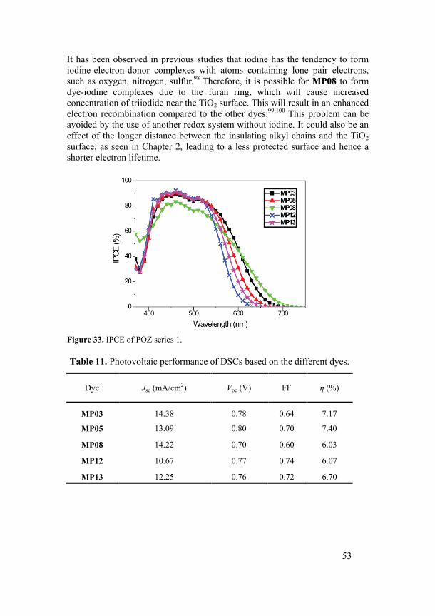
53
It has been observed in previous studies that iodine has the tendency to form iodine-electron-donor complexes with atoms containing lone pair electrons, such as oxygen, nitrogen, sulfur.98 Therefore, it is possible for MP08 to form dye-iodine complexes due to the furan ring, which will cause increased concentration of triiodide near the TiO2 surface. This will result in an enhanced electron recombination compared to the other dyes.99,100 This problem can be avoided by the use of another redox system without iodine. It could also be an effect of the longer distance between the insulating alkyl chains and the TiO2 surface, as seen in Chapter 2, leading to a less protected surface and hence a shorter electron lifetime.
Figure 33. IPCE of POZ series 1.
Table 11. Photovoltaic performance of DSCs based on the different dyes.
Dye Jsc (mA/cm2) Voc (V) FF η (%)
MP03 14.38 0.78 0.64 7.17
MP05 13.09 0.80 0.70 7.40
MP08 14.22 0.70 0.60 6.03
MP12 10.67 0.77 0.74 6.07
MP13 12.25 0.76 0.72 6.70
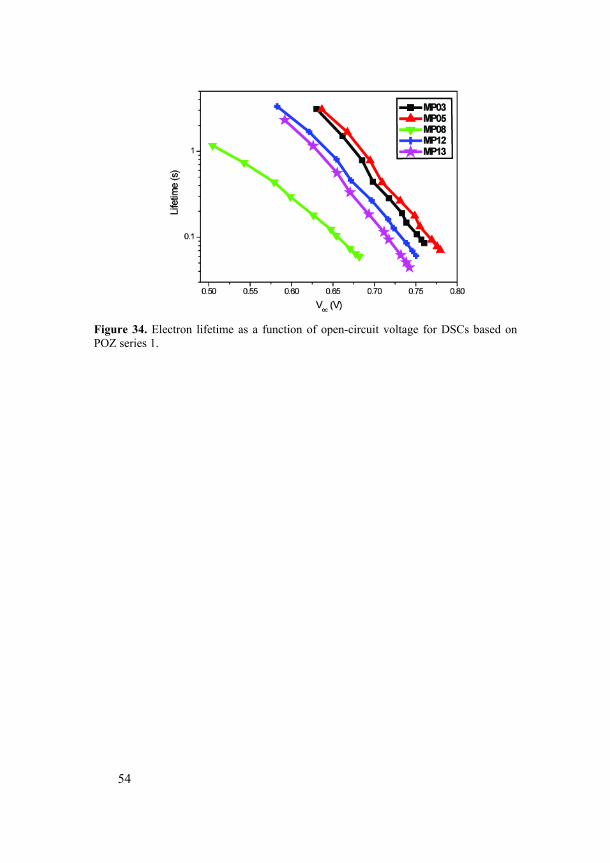
54
Figure 34. Electron lifetime as a function of open-circuit voltage for DSCs based on POZ series 1.
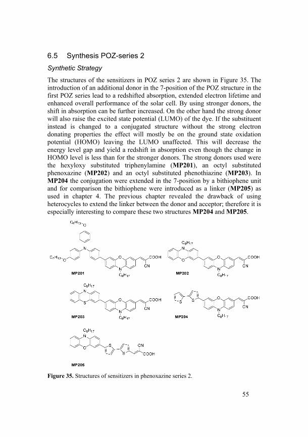
55
6.5 Synthesis POZ-series 2 Synthetic Strategy
The structures of the sensitizers in POZ series 2 are shown in Figure 35. The introduction of an additional donor in the 7-position of the POZ structure in the first POZ series lead to a redshifted absorption, extended electron lifetime and enhanced overall performance of the solar cell. By using stronger donors, the shift in absorption can be further increased. On the other hand the strong donor will also raise the excited state potential (LUMO) of the dye. If the substituent instead is changed to a conjugated structure without the strong electron donating properties the effect will mostly be on the ground state oxidation potential (HOMO) leaving the LUMO unaffected. This will decrease the energy level gap and yield a redshift in absorption even though the change in HOMO level is less than for the stronger donors. The strong donors used were the hexyloxy substituted triphenylamine (MP201), an octyl substituted phenoxazine (MP202) and an octyl substituted phenothiazine (MP203). In MP204 the conjugation were extended in the 7-position by a bithiophene unit and for comparison the bithiophene were introduced as a linker (MP205) as used in chapter 4. The previous chapter revealed the drawback of using heterocycles to extend the linker between the donor and acceptor; therefore it is especially interesting to compare these two structures MP204 and MP205.
Figure 35. Structures of sensitizers in phenoxazine series 2.
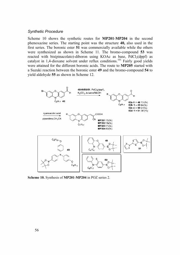
56
Synthetic Procedure
Scheme 10 shows the synthetic routes for MP201-MP204 in the second phenoxazine series. The starting point was the structure 40, also used in the first series. The boronic ester 51 was commercially available while the others were synthesized as shown in Scheme 11. The bromo-compound 53 was reacted with bis(pinacolato)-diboron using KOAc as base, PdCl2(dppf) as catalyst in 1,4-dioxane solvent under reflux conditions.101 Fairly good yields were attained for the different boronic acids. The route to MP205 started with a Suzuki reaction between the boronic ester 49 and the bromo-compound 54 to yield aldehyde 55 as shown in Scheme 12.
Scheme 10. Synthesis of MP201-MP204 in POZ series 2.
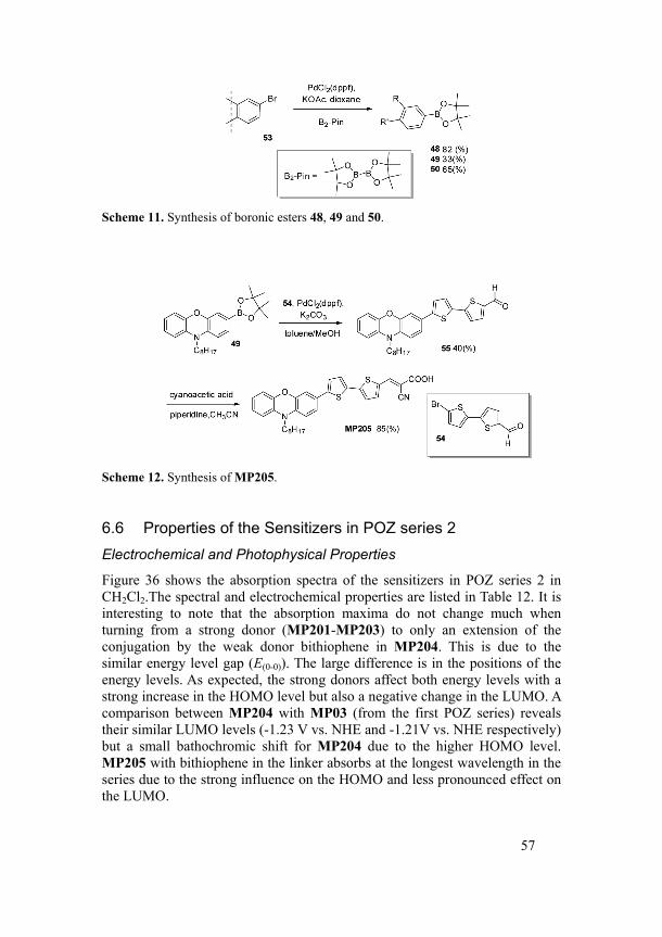
57
Scheme 11. Synthesis of boronic esters 48, 49 and 50.
Scheme 12. Synthesis of MP205.
6.6 Properties of the Sensitizers in POZ series 2 Electrochemical and Photophysical Properties
Figure 36 shows the absorption spectra of the sensitizers in POZ series 2 in CH2Cl2.The spectral and electrochemical properties are listed in Table 12. It is interesting to note that the absorption maxima do not change much when turning from a strong donor (MP201-MP203) to only an extension of the conjugation by the weak donor bithiophene in MP204. This is due to the similar energy level gap (E(0-0)). The large difference is in the positions of the energy levels. As expected, the strong donors affect both energy levels with a strong increase in the HOMO level but also a negative change in the LUMO. A comparison between MP204 with MP03 (from the first POZ series) reveals their similar LUMO levels (-1.23 V vs. NHE and -1.21V vs. NHE respectively) but a small bathochromic shift for MP204 due to the higher HOMO level. MP205 with bithiophene in the linker absorbs at the longest wavelength in the series due to the strong influence on the HOMO and less pronounced effect on the LUMO.
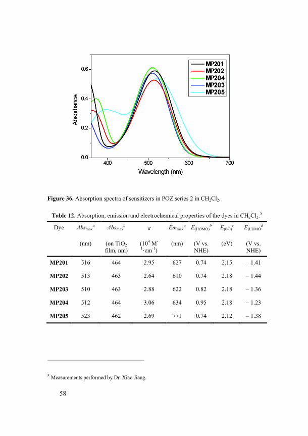
58
Figure 36. Absorption spectra of sensitizers in POZ series 2 in CH2Cl2.
Table 12. Absorption, emission and electrochemical properties of the dyes in CH2Cl2.x
Dye Absmaxa Absmax
a ε Emmaxa E(HOMO)
b E(0-0)c E(LUMO
d
(nm) (on TiO2 film, nm)
(104 M-
1·cm-1) (nm) (V vs.
NHE) (eV) (V vs.
NHE)
MP201 516 464 2.95 627 0.74 2.15 – 1.41
MP202 513 463 2.64 610 0.74 2.18 – 1.44
MP203 510 463 2.88 622 0.82 2.18 – 1.36
MP204 512 464 3.06 634 0.95 2.18 – 1.23
MP205 523 462 2.69 771 0.74 2.12 – 1.38
x Measurements performed by Dr. Xiao Jiang.
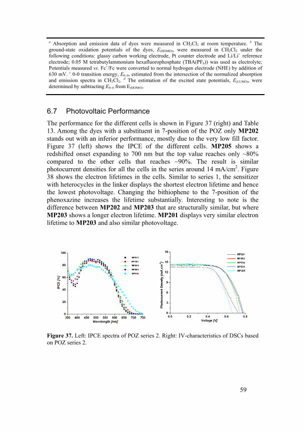
59
a Absorption and emission data of dyes were measured in CH2Cl2 at room temperature. b The ground-state oxidation potentials of the dyes, E(HOMO), were measured in CH2Cl2 under the following conditions: glassy carbon working electrode, Pt counter electrode and Li/Li+ reference electrode; 0.05 M tetrabutylammonium hexafluorophosphate (TBA(PF6)) was used as electrolyte; Potentials measured vs. Fc+/Fc were converted to normal hydrogen electrode (NHE) by addition of 630 mV. c 0-0 transition energy, E0–0, estimated from the intersection of the normalized absorption and emission spectra in CH2Cl2. d The estimation of the excited state potentials, E(LUMO), were determined by subtracting E0–0 from E(HOMO).
6.7 Photovoltaic Performance The performance for the different cells is shown in Figure 37 (right) and Table 13. Among the dyes with a substituent in 7-position of the POZ only MP202 stands out with an inferior performance, mostly due to the very low fill factor. Figure 37 (left) shows the IPCE of the different cells. MP205 shows a redshifted onset expanding to 700 nm but the top value reaches only ~80% compared to the other cells that reaches ~90%. The result is similar photocurrent densities for all the cells in the series around 14 mA/cm2. Figure 38 shows the electron lifetimes in the cells. Similar to series 1, the sensitizer with heterocycles in the linker displays the shortest electron lifetime and hence the lowest photovoltage. Changing the bithiophene to the 7-position of the phenoxazine increases the lifetime substantially. Interesting to note is the difference between MP202 and MP203 that are structurally similar, but where MP203 shows a longer electron lifetime. MP201 displays very similar electron lifetime to MP203 and also similar photovoltage.
Figure 37. Left: IPCE spectra of POZ series 2. Right: IV-characteristics of DSCs based on POZ series 2.
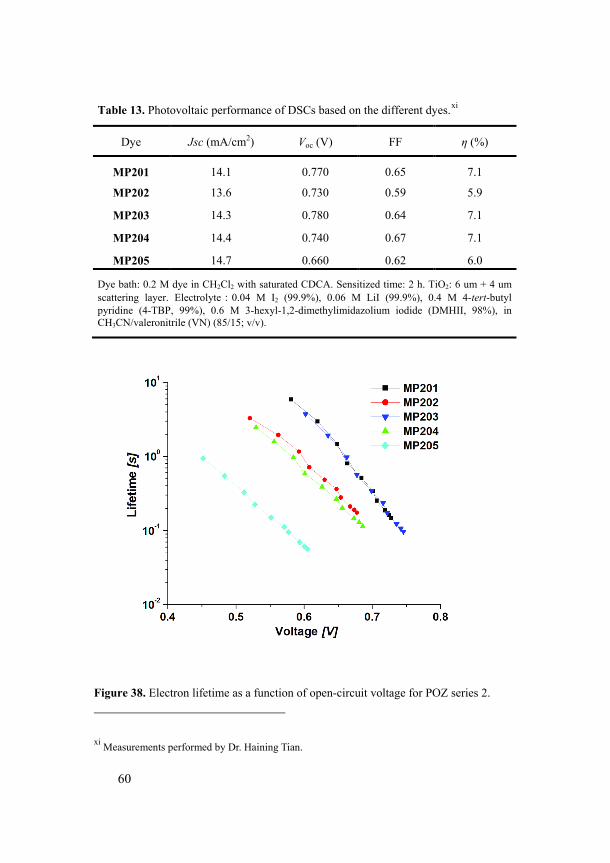
60
Table 13. Photovoltaic performance of DSCs based on the different dyes.xi
Dye Jsc (mA/cm2) Voc (V) FF η (%)
MP201 14.1 0.770 0.65 7.1
MP202 13.6 0.730 0.59 5.9
MP203 14.3 0.780 0.64 7.1
MP204 14.4 0.740 0.67 7.1
MP205 14.7 0.660 0.62 6.0
Dye bath: 0.2 M dye in CH2Cl2 with saturated CDCA. Sensitized time: 2 h. TiO2: 6 um + 4 um scattering layer. Electrolyte:0.04 M I2 (99.9%), 0.06 M LiI (99.9%), 0.4 M 4-tert-butyl pyridine (4-TBP, 99%), 0.6 M 3-hexyl-1,2-dimethylimidazolium iodide (DMHII, 98%), in CH3CN/valeronitrile (VN) (85/15; v/v).
Figure 38. Electron lifetime as a function of open-circuit voltage for POZ series 2.
xi Measurements performed by Dr. Haining Tian.
61
6.8 Conclusions Phenoxazine can be a good alternative to triphenylamine as the donor in sensitizers for DSCs. It has an appropriate oxidation potential and is easy to modify structurally. Substitution on the nitrogen with bulky groups is an efficient way to protect the surface and increase the electron lifetime in the solar cell. A small dihedral angle is necessary for efficient conjugation over the molecule. The introduction of an electron donating moiety in the 7-position of the POZ structure will extend the absorption wavelength, lifting the energy levels and yield better current and photovoltage output of the solar cell. Extension of the conjugated system by the introduction of heterocycles will enhance the light absorbing properties, but will have a negative influence of the overall performance due to the decreased electron lifetime. An interesting development of the POZ dyes would be to use the strategy from chapter 5, with double anchoring groups.
62
7 Concluding Remarks Designing sensitizers for DSC application is a very challenging task. There are a great number of factors that need to be kept in mind. Even if the design looks good on the paper with calculations to support the desired properties of the sensitizer, there are often surprising results when the measurements are analyzed. Contradictions, such as long wave absorption to give high currents can at the same time yield low voltages. The solution is to compromise in order to get as much out of the system as possible.
Today most of the sensitizers are designed for the liquid electrolyte system and later tested in other systems such as solid state or ionic liquid. It will however be necessary to design sensitizers especially for the different systems since there is no good correlation between the efficiencies in different systems. What works in one system doesn’t necessary have to work in another.
An important challenge in designing DSCs is the stability. Many of the most efficient sensitizers don’t show high stability, which will disqualify them for use in commercial application. New dyes with the aim of high stability instead of high performance should be developed. There is also need for further development of reliable tests for stability measurements.
Starting from the sensitizer D5 published in 2006 the development of sensitizers in our group has continued using the strategy of changing one parameter at a time and monitoring the effect. This will help us to get more insight into the complex nature of the DSC system. In the long run, it will enable us to design sensitizers with the properties needed for good performance and high stability.
Six series of organic sensitizers have been designed, synthesized and tested for DSC application. The first four are based on triphenylamine and the last two on phenoxazine.
The dyes were tested in both liquid electrolyte and with solid state hole-conductor. Good efficiencies of over 7% in liquid cells and 4.4% in solid state cells were reached.
Extension of the conjugation is a possible way of increasing the light absorbing properties of the dye; however it can also lead to a decreased electron lifetime and low photovoltage that will result in a decrease in overall efficiency.
Modifying the electron donating properties of the dye can be done by different approaches such as introducing electron donating substituents or using a different donor group with a higher oxidation potential. In both ways the energy levels will be influenced. The energy levels can thereafter be tuned to improve the performance of the solar cell.
63
The modification of the donor seems to be an easier way to increase the performance than changing the linker or acceptor.
One of the most important factors besides the light absorbing properties is the electron lifetime. The solar cells in the thesis that have shown the longest lifetimes have also showed the best overall performance. The introduction of bulky groups such as alkyl chains and twisted aromatic rings can help to protect the semiconductor surface and increase the electron lifetime in the cell, which will improve the overall efficiency.
To conclude: Dye sensitized solar cells is a very interesting concept that has the ability to make a large impact on the society. However, there are still many challenges that need to be faced, and a lot of improvements within the field have to be done, before this will be realized.
64
Acknowledgements First I would like to thank the Swedish Research Council, Swedish Energy Agency, Knut and Alice Wallenberg Foundation, Aulin Erdtmann Foundation and KTH for funding.
Professor Licheng Sun, for accepting me as a PhD student. Especially thanks for the great dinners, both in Sweden and in China.
Professor Anders Hagfeldt, great professor, great guy.
Professor Björn Åkermark for scientific discussions.
Dr. Daniel Hagberg, my tutor, colleague and friend. We had an excellent collaboration.
Dr. Tannia Marinado, thanks for all the help, discussions and pep talk.
Erik Gabrielsson, the living encyclopedia.
Dr. Haining Tian for all the help and discussions, and the badminton games.
Dr. Xiao Jiang, for the great work with my sensitizers.
Dr. Lien Hoa Tran. For help and friendship.
Bao Lin Lee for help with the HR-MS measurements.
Sven Vollmer, Erasmus student, for great job with synthesis and improving the lab environment with your positive energy.
Lena Skowron, you are just great.
Ulla Jacobsson and Henry Challis for all the help with practical stuff.
Torbjörn Norin, Krister Zetterberg, Marcus Angelin, Daniel Hagberg and the Sun group for valuable input on the thesis.
All past and present members of the Sun group. Licheng, Daniel, Samir, Erik, Peng, Lele, Lianpeng, Misha, Yunhua, Lin, Haining, Victor, Jem, Dapeng , Fuyun, Xien, Jingnan
All past and present member of the Hagfeldt group
All past and present coworkers at the department of organic chemistry.
Dr. Nazeeruddin, professor Grätzel and coworkers for the collaboration.
My wonderful family.
Jocy, my beautiful wife. Baby, I’m amazed by you!
65
Appendices Appendix A The following is a description of my contribution to Publications I to VI, as requested by KTH.
Paper I: I performed parts of the synthesis and contributed to the discussion of the project.
Paper II: I performed parts of the synthesis and contributed to the discussion of the project.
Paper III: I performed parts of the synthesis, contributed to the discussion and wrote parts of the manuscript.
Paper IV: Major contribution to the initiation of the project. Performed the synthesis and wrote the majority of the manuscript.
Paper V: Major contribution to the initiation of the project. Performed the synthesis and wrote the majority of the manuscript.
Paper VI: Major contribution to the initiation of the project. Performed the synthesis and wrote the majority of the manuscript.
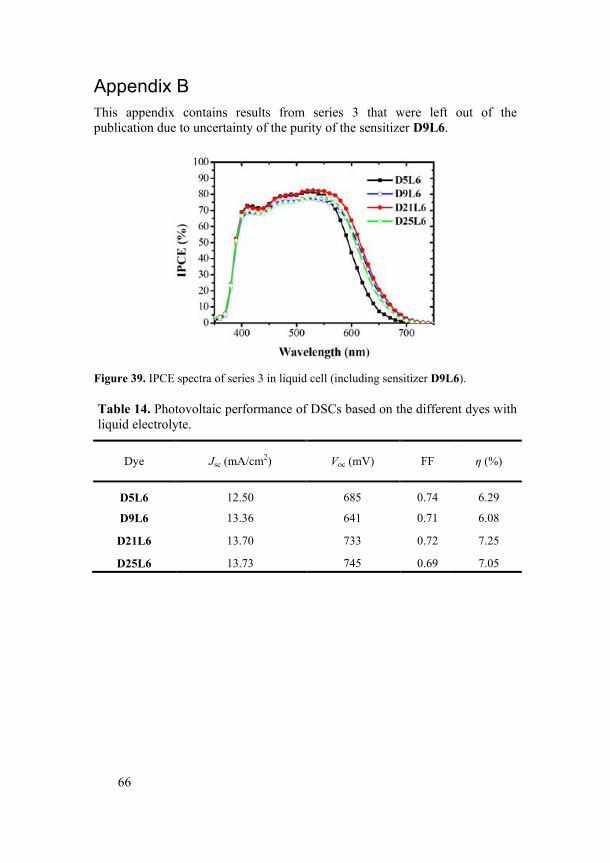
66
Appendix B This appendix contains results from series 3 that were left out of the publication due to uncertainty of the purity of the sensitizer D9L6.
Figure 39. IPCE spectra of series 3 in liquid cell (including sensitizer D9L6).
Table 14. Photovoltaic performance of DSCs based on the different dyes with liquid electrolyte.
Dye Jsc (mA/cm2) Voc (mV) FF η (%)
D5L6 12.50 685 0.74 6.29
D9L6 13.36 641 0.71 6.08
D21L6 13.70 733 0.72 7.25
D25L6 13.73 745 0.69 7.05
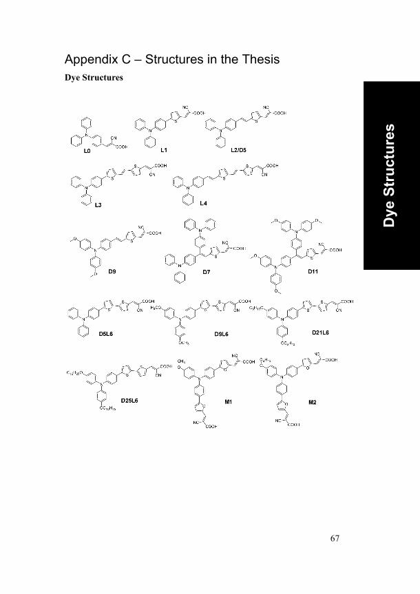
67
Appendix C – Structures in the Thesis Dye Structures
Dye
Str
uctu
res
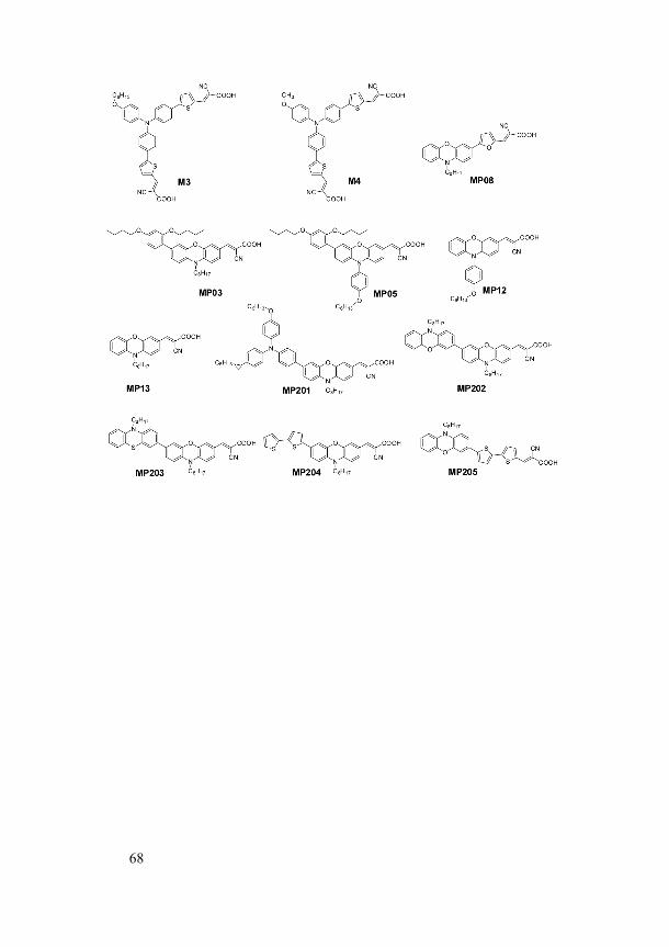
68
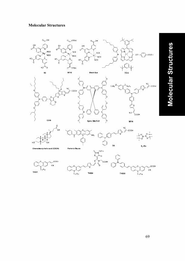
69
Molecular Structures
Mol
ecul
ar S
truc
ture
s
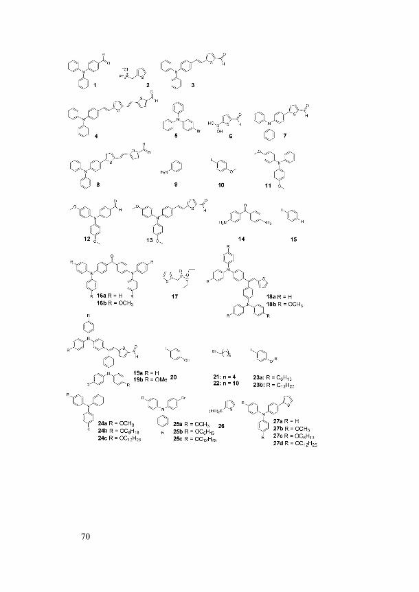
70
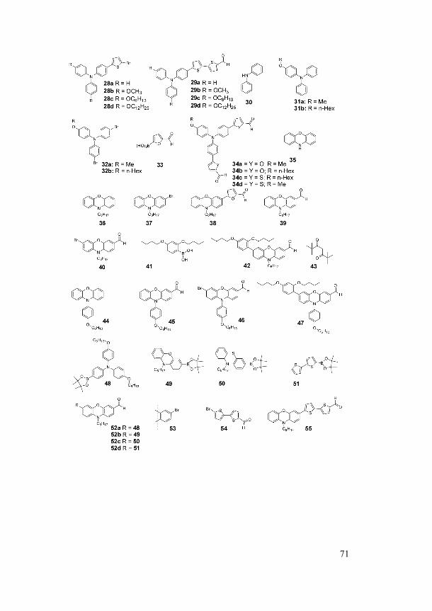
71
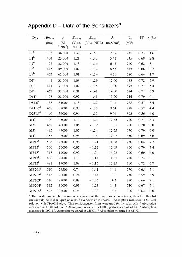
72
Appendix D – Data of the Sensitizersa
Dye Absmax ε E(S+/S) E(S+⁄S*) Jsc Voc FF η (%) (nm) (M-
1·cm-1) (V vs. NHE)
(V vs. NHE) (mA/cm2) (mV)
L0b 373 36 000 1.37 -1.53 2.89 735 0.73 1.6 L1b 404 25 000 1.21 -1.43 5.42 735 0.69 2.8 L2b 427 38 000 1.13 -1.36 6.42 710 0.68 3.1 L3b 445 49 000 1.07 -1.32 6.55 635 0.66 2.7 L4b 463 62 000 1.01 -1.34 4.56 580 0.64 1.7
D5c 441 33 000 1.08 -1.29 12.00 688 0.72 5.9 D7c 441 31 000 1.07 -1.35 11.00 695 0.71 5.4 D9c 462 33 000 0.91 -1.41 14.00 694 0.71 6.9 D11c 458 38 000 0.92 -1.41 13.50 744 0.70 6.1
D5L6d 438 34000 1.13 -1.27 7.41 788 0.57 3.4 D21L6d 458 37000 0.98 -1.35 9.64 798 0.57 4.4 D25L6d 460 36000 0.96 -1.35 9.01 803 0.56 4.0
M1e 490 45000 1.14 -1.24 12.55 710 0.71 6.3 M2e 488 40000 1.05 -1.29 12.31 700 0.70 6.0 M3e 485 49000 1.07 -1.24 12.75 670 0.70 6.0 M4e 483 48000 0.95 -1.35 12.47 650 0.69 5.6
MP03f 506 22000 0.96 – 1.21 14.38 780 0.64 7.2 MP05f 500 20000 0.97 – 1.22 13.09 800 0.70 7.4 MP08f 518 19000 0.92 – 1.24 14.22 700 0.60 6.0 MP12f 486 20000 1.13 – 1.14 10.67 770 0.74 6.1 MP13f 491 19000 1.09 – 1.16 12.25 760 0.72 6.7
MP201g 516 29500 0.74 – 1.41 14.1 770 0.65 7.1 MP202g 513 26000 0.74 – 1.44 13.6 730 0.59 5.9 MP203g 510 29000 0.82 – 1.36 14.3 780 0.64 7.1 MP204g 512 30000 0.95 – 1.23 14.4 740 0.67 7.1 MP205g 523 27000 0.74 – 1.38 14.7 660 0.62 6.0 a The conditions for the measurements were not the same for all sensitizers, therefore this list should only be looked upon as a brief overview of the work. b Absorption measured in CH3CN solution with TBAOH added. Thin semiconductor films were used for the solar cells. c Absorption measured in EtOH solution. d Absorption measured in EtOH, performance of ssDSC. e Absorption measured in EtOH. f Absorption measured in CH2Cl2
g Absorption measured in CH2Cl2
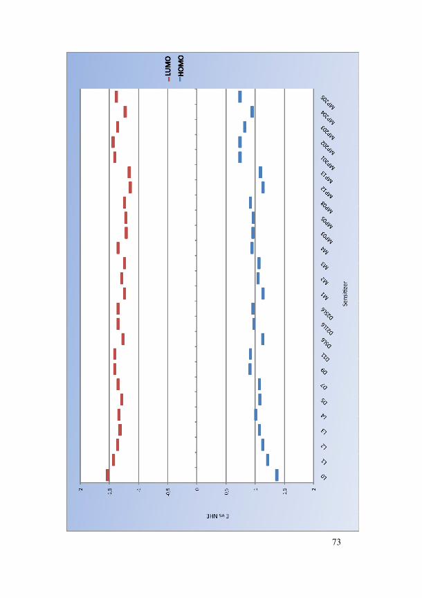
73
74
References
1. Grätzel, M., Acc. Chem. Res. 2009, 42 (11), 1788-1798.
2. Lewis, N. S., Nocera, D. G., Proc. Natl. Acad. Sci. 2006, 103 (43), 15729-15735.
3. Boyle, G., Open, U., Renewable energy: power for a sustainable future. Oxford University Press in association with the Open University: Oxford, 1996.
4. Grätzel, M., Philos. Trans. R. Soc. London, A 2007, 365 (1853), 993-1005.
5. Hagfeldt, A., Boschloo, G., Sun, L. C., Kloo, L., Pettersson, H., Chem. Rev. 2010, 110 (11), 6595-6663.
6. Chapin, D. M., Fuller, C. S., Pearson, G. L., J. Appl. Phys. 1954, 25 (5), 676-677.
7. Gerischer, H., Michel-Beyerle, M. E., Rebentrost, F., Tributsch, H., Electrochim. Acta 1968, 13 (6), 1509-1515.
8. Tsubomura, H., Matsumura, M., Nomura, Y., Amamiya, T., Nature 1976, 261 (5559), 402-403.
9. Desilvestro, J., Grätzel, M., Kavan, L., Moser, J., Augustynski, J., J. Am. Chem. Soc. 1985, 107 (10), 2988-2990.
10. O'Regan, B. G., M, Nature 1991, 353, 737-740.
11. Ardo, S., Meyer, G. J., Chem. Soc. Rev. 2009, 38 (1), 115-164.
12. Nazeeruddin, M. K., Pechy, P., Renouard, T., Zakeeruddin, S. M., Humphry-Baker, R., Comte, P., Liska, P., Cevey, L., Costa, E., Shklover, V., Spiccia, L., Deacon, G. B., Bignozzi, C. A., Grätzel, M., J. Am. Chem. Soc. 2001, 123, 1613-1624.
13. Nazeeruddin, M. K., Zakeeruddin, S. M., Humphry-Baker, R., Jirousek, M., Liska, P., Vlachopoulos, N., Shklover, V., Fischer, C. H., Grätzel, M., Inorg. Chem. 1999, 38 (26), 6298-6305.
14. Nazeeruddin, M. K., Kay, A., Rodicio, I., Humphry-baker, R., Muller, E., Liska, P., Vlachopoulos, N., Grätzel, M., J. Am. Chem. Soc. 1993, 115 (14), 6382-6390.
15. Nazeeruddin, M. K., Pechy, P., Grätzel, M., Chem. Commun. 1997, (18), 1705-1706.
75
16. Chiba, Y., Islam, A., Watanabe, Y., Komiya, R., Koide, N., Han, L. Y., Jpn. J. Appl. Phys. Part 2 - Lett. Express Lett. 2006, 45 (24-28), 638-640.
17. Lu, H.-P., Tsai, C.-Y., Yen, W.-N., Hsieh, C.-P., Lee, C.-W., Yeh, C.-Y., Diau, E. W.-G., J. Phys. Chem. C 2009, 113 (49), 20990-20997.
18. Bessho, T., Zakeeruddin, S., Yeh, C. Y., Diau, E. G., Grätzel, M., Angew. Chem., Int. Ed. 2010, 49 (37), 6646-6649.
19. Zeng, W., Cao, Y., Bai, Y., Wang, Y., Shi, Y., Zhang, M., Wang, F., Pan, C., Wang, P., Chem. Mater. 2010, 22, 1915-1925.
20. Pettersson, H., Gruszecki, T., Bernhard, R., Haggman, L., Gorlov, M., Boschloo, G., Edvinsson, T., Kloo, L., Hagfeldt, A., Progress in Photovoltaics 2007, 15 (2), 113-121.
21. Kay, A., Grätzel, M., Sol. Energy Mater. Sol. Cells 1996, 44 (1), 99-117.
22. Saito, Y., Kitamura, T., Wada, Y., Yanagida, S., Chem. Lett. 2002, (10), 1060-1061.
23. Bay, L., West, K., Winther-Jensen, B., Jacobsen, T., Sol. Energy Mater. Sol. Cells 2006, 90 (3), 341-351.
24. Choi, H., Baik, C., Kang, S. O., Ko, J., Kang, M. S., Nazeeruddin, M. K., Grätzel, M., Angew. Chem., Int. Ed. 2008, 47 (2), 327-330.
25. Gorlov, M., Kloo, L., Dalton Trans. 2008, (20), 2655-2666.
26. Bach, U., Lupo, D., Comte, P., Moser, J. E., Weissortel, F., Salbeck, J., Spreitzer, H., Grätzel, M., Nature 1998, 395 (6702), 583-585.
27. Cappel, U. B., Karlsson, M. H., Pschirer, N. G., Eickemeyer, F., Schoneboom, J., Erk, P., Boschloo, G., Hagfeldt, A., J. Phys. Chem. C 2009, 113 (33), 14595-14597.
28. Liu, X. Z., Zhang, W., Uchida, S., Cai, L. P., Liu, B., Ramakrishna, S., Adv. Mater. 2010, 22 (20).
29. Tian, H., Jiang, X., Yu, Z., Kloo, L., Hagfeldt, A., Sun, L., Angew. Chem. Int. Ed. 2010, 49 (40), 7328-7331.
30. Feldt, S. M., Gibson, E. A., Gabrielsson, E., Sun, L., Boschloo, G., Hagfeldt, A., J. Am. Chem. Soc. 2010, 132 (46), 16714-16724.
31. Wang, M., Chamberland, N., Breau, L., Moser, J.-E., Humphry-Baker, R., Marsan, B., Zakeeruddin, S. M., Grätzel, M., Nat Chem 2010, 2 (5), 385-389.
32. Ooyama, Y., Harima, Y., Eur. J. Org. Chem. 2009, (18), 2903-2934.
76
33. Mishra, A., Fischer, M. K. R., Bäuerle, P., Angew. Chem. Int. Ed. 2009, 48 (14), 2474-2499.
34. Robertson, N., Angew. Chem. Int. Ed. 2006, 45 (15), 2338-2345.
35. Ito, S., Miura, H., Uchida, S., Takata, M., Sumioka, K., Liska, P., Comte, P., Pechy, P., Graetzel, M., Chem. Commun. 2008, (41), 5194-5196.
36. Li, C., Yum, J. H., Moon, S. J., Herrmann, A., Eickemeyer, F., Pschirer, N. G., Erk, P., Schoeboom, J., Mullen, K., Grätzel, M., Nazeeruddin, M. K., ChemSusChem 2008, 1 (7), 615-618.
37. Edvinsson, T., Li, C., Pschirer, N., Schoneboom, J., Eickemeyer, F., Sens, R., Boschloo, G., Herrmann, A., Mullen, K., Hagfeldt, A., J. Phys. Chem. C 2007, 111 (42), 15137-15140.
38. Hara, K., Wang, Z.-S., Sato, T., Furube, A., Katoh, R., Sugihara, H., Dan-oh, Y., Kasada, C., Shinpo, A., Suga, S., J. Phys. Chem. B 2005, 109 (32), 15476-15482.
39. Wang, Z. S., Koumura, N., Cui, Y., Takahashi, M., Sekiguchi, H., Mori, A., Kubo, T., Furube, A., Hara, K., Chem. Mater. 2008, 20 (12), 3993-4003.
40. Kim, S., Lee, J. K., Kang, S. O., Ko, J., Yum, J. H., Fantacci, S., De Angelis, F., Di Censo, D., Nazeeruddin, M. K., Grätzel, M., J. Am. Chem. Soc. 2006, 128 (51), 16701-16707.
41. Galoppini, E., Coord. Chem. Rev. 2004, 248 (13-14), 1283-1297.
42. Wang, P., Klein, C., Moser, J. E., Humphry-Baker, R., Cevey-Ha, N. L., Charvet, R., Comte, P., Zakeeruddin, S. M., Grätzel, M., J. Phys. Chem. B 2004, 108 (45), 17553-17559.
43. Unno, M., Kakiage, K., Yamamura, M., Kogure, T., Kyomen, T., Hanaya, M., Appl. Organomet. Chem. 2009, 24 (3), 247-250.
44. McNamara, W. R., Milot, R. L., Song, H.-e., Snoeberger Iii, R. C., Batista, V. S., Schmuttenmaer, C. A., Brudvig, G. W., Crabtree, R. H., Energy Environ. Sci. 2010, 3 (7), 917-923.
45. Hara, K., Dan-Oh, Y., Kasada, C., Ohga, Y., Shinpo, A., Suga, S., Sayama, K., Arakawa, H., Langmuir 2004, 20 (10), 4205-4210.
46. Zollinger, H., Color chemistry: syntheses, properties, and applications of organic dyes and pigments. Verlag Helvetica Chimica Acta, Wiley-VCH: Zürich, Weinheim, 2003.
77
47. Hassan, J., Sevignon, M., Gozzi, C., Schulz, E., Lemaire, M., Chem. Rev. 2002, 102 (5), 1359-1470.
48. Wolfe, J. P., Wagaw, S., Marcoux, J.-F. o., Buchwald, S. L., Acc. Chem. Res. 1998, 31 (12), 805-818.
49. Wittig, G., J. Organomet. Chem. 1975, 100 (1), 279-287.
50. Blaser, D., Calmes, M., Daunis, J., Natt, F., Tardydelassus, A., Jacquier, R., Org. Prep. Proced. Int. 1993, 25 (3), 338-341.
51. Wommack, J. B., Barbee, T. G., Thoennes, D. J., McDonald, M. A., Pearson, D. E., J. Heterocycl. Chem. 1969, 6 (2), 243-245.
52. Nobel prize homepage. http://nobelprize.org/nobel_prizes/chemistry/laureates/2010/suzuki.html/ (accessed 2 Feb 2011).
53. Suzuki, A., J. Organomet. Chem. 1999, 576 (1-2), 147-168.
54. Smith, M., March, J., March's advanced organic chemistry: reactions, mechanisms, and structure, pp1225-1228. Wiley: New York, 2001.
55. List, B., Angew. Chem. Int. Ed. 2010, 49 (10), 1730-1734.
56. Hagberg, D. P., Edvinsson, T., Marinado, T., Boschloo, G., Hagfeldt, A., Sun, L. C., Chem. Commun. 2006, (21), 2245-2247.
57. Kitamura, T., Ikeda, M., Shigaki, K., Inoue, T., Anderson, N. A., Ai, X., Lian, T. Q., Yanagida, S., Chem. Mater. 2004, 16 (9), 1806-1812.
58. Hara, K., Kurashige, M., Dan-oh, Y., Kasada, C., Shinpo, A., Suga, S., Sayama, K., Arakawa, H., New J. Chem. 2003, 27 (5), 783-785.
59. Hepperle, S. S., Li, Q. B., East, A. L. L., Journal of Physical Chemistry A 2005, 109 (48), 10975-10981.
60. Sayama, K., Tsukagoshi, S., Hara, K., Ohga, Y., Shinpou, A., Abe, Y., Suga, S., Arakawa, H., J. Phys. Chem. B 2002, 106 (6), 1363-1371.
61. Liu, D., Fessenden, R. W., Hug, G. L., Kamat, P. V., J. Phys. Chem. B 1997, 101 (14), 2583-2590.
62. Choi, H., Baik, C., Kim, H. J., Kim, J. J., Song, K., Kang, S. O., Ko, J., Bull. Korean Chem. Soc. 2007, 28 (11), 1973-1979.
63. Spraul, B. K., Suresh, S., Sassa, T., Ángeles Herranz, M., Echegoyen, L., Wada, T., Perahia, D., Smith Jr, D. W., Tetrahedron Lett. 2004, 45 (16), 3253-3256.
78
64. Wadsworth, W. S., Emmons, W. D., J. Am. Chem. Soc. 1961, 83 (7), 1733-1738.
65. Zhang, Z. P., Evans, N., Zakeeruddin, S. M., Humphry-Baker, R., Grätzel, M., J. Phys. Chem. C 2007, 111 (1), 398-403.
66. Schlichthorl, G., Huang, S. Y., Sprague, J., Frank, A. J., J. Phys. Chem. B 1997, 101 (41), 8141-8155.
67. Snaith, H. J., Grätzel, M., Appl. Phys. Lett. 2006, 89 (26), 262114
68. Kim, S., Choi, H., Baik, C., Song, K., Kang, S. O., Ko, J., Tetrahedron 2007, 63 (46), 11436-11443.
69. Zhang, G., Bala, H., Cheng, Y., Shi, D., Lv, X., Yu, Q., Wang, P., Chem. Commun. 2009, (16), 2198-2200.
70. Li, R., Lv, X., Shi, D., Zhou, D., Cheng, Y., Zhang, G., Wang, P., J. Phys. Chem. C 2009, 113 (17), 7469-7479.
71. Chen, P., Yum, J. H., Angelis, F. D., Mosconi, E., Fantacci, S., Moon, S.-J., Baker, R. H., Ko, J., Nazeeruddin, M. K., Grätzel, M., Nano Lett. 2009, 9 (6), 2487-2492.
72. Yum, J. H., Hagberg, D. P., Moon, S. J., Karlsson, K. M., Marinado, T., Sun, L. C., Hagfeldt, A., Nazeeruddin, M. K., Grätzel, M., Angew. Chem., Int. Ed. 2009, 48 (9), 1576-1580.
73. Nazeeruddin, M. K., Humphry-Baker, R., Liska, P., Grätzel, M., J. Phys. Chem. B 2003, 107 (34), 8981-8987.
74. Abbotto, A., Manfredi, N., Marinzi, C., De Angelis, F., Mosconi, E., Yum, J. H., Zhang, X. X., Nazeeruddin, M. K., Grätzel, M., Energy Environ. Sci. 2009, 2 (10), 1094-1101.
75. Mikroyannidis, J. A., Suresh, P., Roy, M. S., Sharma, G. D., J. Power Sources 2010, 195 (9), 3002-3010.
76. Xue-Hua, Z., Yi-Shan, Y. A. O., Chao, L. I., Wei-Bo, W., Xue-Xin, C., Xue-Song, W., Bao-Wen, Z., Chin. J. Chem. 2008, 26 (5), 929-934.
77. Xu, W., Peng, B., Chen, J., Liang, M., Cai, F., J. Phys. Chem. C 2008, 112 (3), 874-880.
78. Park, S. S., Won, Y. S., Choi, Y. C., Kim, J. H., Energy Fuels 2009, 23 (7), 3732-3736.
79. Cho, M. J., Park, S. S., Yang, Y. S., Kim, J. H., Choi, D. H., Synth. Met. 2010, 160 (15-16), 1754-1760.
79
80. Hagberg, D. P., Marinado, T., Karlsson, K. M., Nonomura, K., Qin, P., Boschloo, G., Brinck, T., Hagfeldt, A., Sun, L., J. Org. Chem. 2007, 72 (25), 9550-9556.
81. Lin, J. T., Chen, P. C., Yen, Y. S., Hsu, Y. C., Chou, H. H., Yeh, M. C. P., Org. Lett. 2009, 11 (1), 97-100.
82. Yen, Y. S., Hsu, Y. C., Lin, J. T., Chang, C. W., Hsu, C. P., Yin, D. J., J. Phys. Chem. C 2008, 112 (32), 12557-12567.
83. Kroeze, J. E., Hirata, N., Koops, S., Nazeeruddin, M. K., Schmidt-Mende, L., Grätzel, M., Durrant, J. R., J. Am. Chem. Soc. 2006, 128 (50), 16376-16383.
84. Wang, Z.-S., Sugihara, H., Langmuir 2006, 22 (23), 9718-9722.
85. Nazeeruddin, M. K., Pechy, P., Renouard, T., Zakeeruddin, S. M., Humphry-Baker, R., Comte, P., Liska, P., Cevey, L., Costa, E., Shklover, V., Spiccia, L., Deacon, G. B., Bignozzi, C. A., Grätzel, M., J. Am. Chem. Soc. 2001, 123 (8), 1613-1624.
86. Huang, S.-T., Hsu, Y.-C., Yen, Y.-S., Chou, H. H., Lin, J. T., Chang, C.-W., Hsu, C.-P., Tsai, C., Yin, D.-J., J. Phys. Chem. C 2008, 112 (49), 19739–19747.
87. Liang, Y., Peng, B., Liang, J., Tao, Z., Chen, J., Org. Lett. 2010, 12 (6), 1204-1207.
88. Ning, Z., Tian, H., Chem. Commun. 2009, (37), 5483-5495.
89. Tian, H., Yang, X., Cong, J., Chen, R., Teng, C., Liu, J., Hao, Y., Wang, L., Sun, L., Dyes Pigm. 2010, 84 (1), 62-68.
90. Zhu, X. Q., Dai, Z., Yu, A., Wu, S. A., Cheng, J. P., J. Phys. Chem. B 2008, 112 (37), 11694-11707.
91. Wu, T.-Y., Tsao, M.-H., Chen, F.-L., Su, S.-G., Chang, C.-W., Wang, H.-P., Lin, Y.-C., Ou-Yang, W.-C., Sun, I.-W., Int. J. Mol. Sci. 2010, 11 (1), 329-353.
92. Tian, H., Yang, X., Chen, R., Pan, Y., Li, L., Hagfeldt, A., Sun, L., Chem. Commun. 2007, (36), 3741-3743.
93. Wu, W., Yang, J., Hua, J., Tang, J., Zhang, L., Long, Y., Tian, H., J. Mater. Chem. 2010, 20 (9), 1772-1779.
94. Tian, H. N., Yang, X. C., Cong, J. Y., Chen, R. K., Liu, J., Hao, Y., Hagfeldt, A., Sun, L. C., Chem. Commun. 2009, (41), 6288-6290.
95. Tian, H. N., Yang, X. C., Chen, R. K., Hagfeldt, A., Sun, L. C., Energy Environ. Sci. 2009, 2 (6), 674-677.
80
96. Shafir, A., Buchwald, S. L., J. Am. Chem. Soc. 2006, 128 (27), 8742-8743.
97. Vezzu, D. A. K., Deaton, J. C., Shayeghi, M., Li, Y., Huo, S., Org. Lett. 2009, 11 (19), 4310-4313.
98. Tsubomura, H., Lang, R. P., J. Am. Chem. Soc. 1961, 83 (9), 2085-2092.
99. Marinado, T., Nonomura, K., Nissfolk, J., Karlsson, M. K., Hagberg, D. P., Sun, L., Mori, S., Hagfeldt, A., Langmuir 2009, 26 (4), 2592-2598.
100. O'Regan, B. C., Lopez-Duarte, I., Martinez-Diaz, M. V., Forneli, A., Albero, J., Morandeira, A., Palomares, E., Torres, T., Durrant, J. R., J. Am. Chem. Soc. 2008, 130 (10), 2906-2907.
101. Yougnia, R., Rochais, C., Oliveira Santos, J. S.-d., Dallemagne, P., Rault, S., Tetrahedron 2010, 66 (15), 2803-2808.