
DESIGN STANDARDS MANUAL FOR WATER AND WASTEWATER SYSTEMS · Design Standards Manual For Water And...
63
City of Phoenix Water Services Department Draft DESIGN STANDARDS MANUAL FOR WATER AND WASTEWATER SYSTEMS February 29 th , 2012 Water Services Department 200 W. Washington Street Phoenix, Arizona 85003-1697 Phone: (602) 262-1826 Fax: (602) 495-5843
Transcript of DESIGN STANDARDS MANUAL FOR WATER AND WASTEWATER SYSTEMS · Design Standards Manual For Water And...

City of Phoenix Water Services Department
Draft
DESIGN STANDARDS MANUAL FOR
WATER AND WASTEWATER SYSTEMS
February 29th, 2012
Water Services Department 200 W. Washington Street
Phoenix, Arizona 85003-1697 Phone: (602) 262-1826
Fax: (602) 495-5843

City of Phoenix Water Services Department Design Standards Manual For Water And Wastewater Systems ii
Table of Contents CHAPTER 1 INTRODUCTION
1.1 PURPOSE OF MANUAL 1.2 AUTHORITY 1.3 REVISIONS AND PUBLIC COMMENTS 1.4 ORGANIZATION AND INTERPRETATION OF MANUAL 1.5 DEFINITIONS 1.6 ABBREVIATIONS 1.7 STANDARD SPECIFICATIONS AND DETAILS
CHAPTER 2 DEVELOPMENT COORDINATION BY DEPARTMENTS
2.1 GENERAL 2.2 WATER SERVICES DEPARTMENT (WSD)
2.2.1 General 2.2.2 WSD, Divisions of Responsibility 2.2.3 WSD, Development Services Provided
2.3 PLANNING AND DEVELOPMENT DEPARTMENT (P&D) 2.4 PUBLIC WORKS DEPARTMENT - ENGINEERING AND ARCHITECTURAL
SERVICES (EAS) 2.5 STREET TRANSPORTATION DEPARTMENT (STD) AND AVIATION
DEPARTMENT
CHAPTER 3 GENERAL WATER AND SEWER DESIGN CRITERIA
3.1 GENERAL DESIGN CRITERIA/CONSIDERATIONS 3.1.1 Jurisdictional Agency Approvals 3.1.2 Environmental and Cultural Regulatory Requirements 3.1.3 Community Notification and Involvement 3.1.4 Subsurface Investigations
3.2 ALIGNMENT AND EASEMENT REQUIREMENTS 3.2.1 General 3.2.2 Residential Development with Private Access Ways 3.2.3 Residential Development located within the City’s Infill Incentive District 3.2.4 All other Easements 3.2.5 Structures Adjacent to Existing Water & Sewer Easements
3.3 SUBMITTALS 3.3.1 Water and Sewer Master Plans and Reports 3.3.2 Design Reports 3.3.3 Construction Plans and Technical Specifications – CIP Projects and Projects with City Financial Participation

City of Phoenix Water Services Department Design Standards Manual For Water And Wastewater Systems iii
3.3.4 Construction Plans – Private Development Projects 3.3.5 Record Drawings
3.4 WATER DEMAND AND SEWER DESIGN FLOWS 3.4.1 General 3.4.2 Water and Sewer Design Flows 3.4.3 Water Peak Flow 3.4.4 Sewer Peak Flow
CHAPTER 4 WATER DISTRIBUTION AND TRANSMISSION SYSTEMS
4.1 WATER SYSTEM OVERVIEW 4.1.1 Pressure Zones
4.2 WATER MAIN DESIGN CRITERIA APPLICABLE TO BOTH DISTRIBUTION AND
TRANSMISSION MAINS 4.2.1 Water Main Extensions 4.2.2 Water Main Classifications 4.2.3 Water Main Design 4.2.4 Fire Flow Demand 4.2.5 Hydraulic Requirements 4.2.6 Thrust Restraint for Distribution Mains 4.2.7 Corrosion Protection/Ductile Iron Pipe 4.2.8 Separation from Sanitary Sewer Mains 4.2.9 Separation from Sanitary Sewer Connections 4.2.10 Separation from Storm Drains and Culverts 4.2.11 Separation from Other Utilities 4.2.12 Cross Connections and Backflow Prevention 4.2.13 Shop Drawings
4.3 ADDITIONAL DESIGN CRITERIA ONLY APPLICABLE TO DISTRIBUTION MAINS 4.3.1 General 4.3.2 Water Plan Requirements – Check Lists 4.3.3 Acceptable Pipe Materials 4.3.4 Pipe Sizing for Distribution Mains 4.3.5 Location/Alignment 4.3.6 Distribution Main Cover 4.3.7 Line Valves 4.3.8 Service Connections and Meters on Distribution Water Mains 6-inches and Larger 4.3.9 Service Connections and Meters from Substandard Distribution Mains (smaller than 6-inch diameter) 4.3.10 Water Meters and Sizing Guidelines
4.4 ADDITIONAL DESIGN CRITERIA ONLY APPLICABLE TO TRANSMISSION MAINS 4.4.1 General 4.4.2 Acceptable Pipe Materials 4.4.3 Pipe Sizing 4.4.4 Location/Alignment 4.4.5 Cover 4.4.6 Line Valves 4.4.7 Restraint Systems 4.4.8 Corrosion Protection 4.4.9 Side Outlets 4.4.10 Bypass Assemblies

City of Phoenix Water Services Department Design Standards Manual For Water And Wastewater Systems iv
4.4.11 Air/Vacuum Valve Assemblies 4.4.12 Access Outlets for 42-inch Mains and Larger 4.4.13 Use of Fire Hydrants and Placement 4.4.14 Testing and Final Acceptance 4.4.15 Transmission Main Plan Requirements - Check Lists
4.5 FIRE LINE SYSTEMS 4.5.1 General 4.5.2 Acceptable Pipe Materials 4.5.3 Design Requirements 4.5.4 Fire Line Plan Requirements - Check List 4.5.5 Plans Processing Guidelines
4.6 IRRIGATION SYSTEMS AND WATER FEATURES
4.6.1 General 4.6.2 Backflow Prevention 4.6.3 Service Connections/Meters 4.6.4 Landscape Water Permit
4.7 WATER ABANDONMENT
4.7.1 Plan Requirements Checklist 4.7.2 Abandonment Methods
4.8 FIRE HYDRANT REQUIREMENTS
4.8.1 General Location and Design Requirements 4.8.2 Residential Subdivision Hydrant Location Standards 4.8.3 Commercial and Multifamily Hydrant Location Standards 4.8.4 Private Fire Hydrants 4.8.5 Maximum Fire Hydrant Spacing 4.8.6 Fire Hydrant Relocations
CHAPTER 5 Wastewater Collection System
5.1 GENERAL REQUIREMENTS 5.1.1 Arizona Aquifer Protection Permit Requirements 5.1.2 Maricopa County Health Code Requirements 5.1.3 City Code Requirements
5.2 GRAVITY SANITARY SEWER LINES
5.2.1 General 5.2.2 Acceptable Pipe Materials 5.2.3 Pipe Sizing 5.2.4 Slope 5.2.5 Alignment 5.2.6 Cover 5.2.7 Sewer Main Connections at Manholes 5.2.8 Cross Connections Prohibited 5.2.9 Separation from Water Mains 5.2.10 Separation from Water Supply System Structures 5.2.11 Separation from Storm Drains and Culverts 5.2.12 Separation from Other Utilities 5.2.13 Buoyancy 5.2.14 Trenching, Bedding, and Backfill 5.2.15 Testing 5.2.16 Depressed Sewers

City of Phoenix Water Services Department Design Standards Manual For Water And Wastewater Systems v
5.3 MANHOLES 5.3.1 General 5.3.2 Manhole Locations 5.3.3 Manhole Spacing 5.3.4 Manhole Diameter 5.3.5 Metered Manholes 5.3.6 Clean Outs 5.3.7 Manhole Stub Outs and Knock Outs 5.3.8 Drop Sewer Connections 5.3.9 Flow Channel 5.3.10 Bench 5.3.11 Water Tightness 5.3.12 Testing 5.3.13 Corrosion Protection for Manholes 5.3.14 Junction Structures 5.3.15 Insecticide Coating
5.4 SERVICE CONNECTIONS
5.4.1 General 5.4.2 Service Connection Sizes 5.4.3 Service Connections in Manholes 5.4.4 Service Connection Installation Requirements
5.5 WASTEWATER LIFT STATIONS AND FORCE MAINS 5.6 ALLOWABLE DISCHARGES AND PRELIMINARY TREATMENT 5.7 SEPTIC SYSTEMS WITHIN THE CITY OF PHOENIX
5.7.1 City Ordinances Which Apply to Septic Systems 5.7.2 When Septic Systems May be Allowed 5.7.3 Existing Septic Systems
Appendix A – WSD Polices and Procedures Website link to Water and Sewer Policies APPENDIX B - Maricopa Association of Governments Specifications and Details
Website link to MAG Specifications and Details Website link to the City of Phoenix Supplement to MAG Specifications and Details
APPENDIX C - Arizona Administrative Code Website link to the Arizona Administrative Code
APPENDIX D - The Code of the City of Phoenix
APPENDIX E - Definitions and Terms APPENDIX F - Abbreviations

City of Phoenix Water Services Department Design Standards Manual For Water And Wastewater Systems vi
Table of Figures Figure 4.1 Typical Major Pressure Zone Configuration

City of Phoenix Water Services Department Design Standards Manual For Water And Wastewater Systems vii
Table of Tables Table 3.1 Minimum Easement Widths for Water Mains Table 3.2 Minimum Easement Widths for Sewer Mains Table 3.3 Water and Sewer Design Flows Table 4.1 Minimum Water Distribution Grid System Table 4.2 Valve Spacing Table 4.3 Water Meter Sizing Table Table 4.4 Allowable Velocity/Headloss Table 4.5 Line Valve Spacing Table 4.6 Fire Hydrant Spacing Table 5.1 Design Velocity Table 5.2 Maximum Manhole Spacing Table 5.3 Minimum Manhole Diameters Table 5.4 Service Connection Sizes
City of Phoenix Water Services Department Design Standards Manual For Water And Wastewater Systems viii
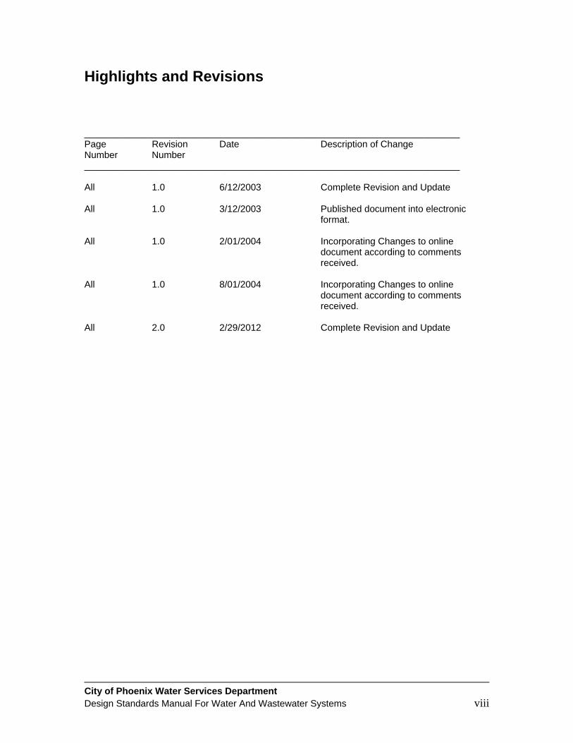
Highlights and Revisions ________________________________________________________________________ Page Revision Date Description of Change Number Number ________________________________________________________________________ All 1.0 6/12/2003 Complete Revision and Update All 1.0 3/12/2003 Published document into electronic format. All 1.0 2/01/2004 Incorporating Changes to online
document according to comments received.
All 1.0 8/01/2004 Incorporating Changes to online
document according to comments received.
All 2.0 2/29/2012 Complete Revision and Update
City of Phoenix Water Services Department Design Standards Manual For Water And Wastewater Systems 1
CHAPTER 1 INTRODUCTION 1.1 PURPOSE OF MANUAL
The purpose of this manual is to provide guidelines and minimum design criteria for the design of water and wastewater piping systems for the City of Phoenix either as part of Capital Improvement Program (CIP) projects or as private development projects that will construct and dedicate the systems to the City. The manual applies to existing systems being expanded, modified, upgraded and rehabilitated as well as to the construction of new mains. The manual is not intended to be used as a construction specification. All units of measurement used in this manual are United States standard measure unless otherwise noted. The Water Services Department (WSD) has other design manuals available for the facilities (booster stations, lift stations, reservoirs, and pressure reducing valve stations) located on our website.
1.2 AUTHORITY
The design standards set forth in this manual are adopted pursuant to the authority granted in ARS 9-672 and Section 37-2, 37-3 and 28-3 of the Phoenix City Code.
1.3 REVISIONS AND PUBLIC COMMENTS
This manual may be revised periodically. Proposed revisions will be posted on the City of Phoenix Water Services Department (WSD) web site for a period of 60 days prior to implementation unless the revision is required to comply with Federal, State, County, and City laws, regulations, ordinances, or codes. In order to review proposed revisions, go to the following website: http://www.phoenix.gov/waterservices/design/index.html All proposed revisions will be listed on this page. If proposed revisions are listed, all comments received during the public comment period will be considered and responded to. At any time if you have a comment on the WSD Design Standards Manual, you may send an email to the WSD provided on the website. These comments will also be reviewed and responded to.
1.4 ORGANIZATION AND INTERPRETATION OF MANUAL
This manual is composed of written engineering standards, references to established standards of other organizations and agencies and standard details of the WSD. The Director of the WSD, whose interpretation shall be binding and controlling in its application, shall make the interpretation of any section or of differences between sections. NOTE: Any deviations from the Standards in this manual shall require a technical appeal to the WSD Directors Representative. This appeal application is submitted to the Planning and Development Department (P&D) through the standard technical appeal process.
1.5 DEFINITIONS

City of Phoenix Water Services Department Design Standards Manual For Water And Wastewater Systems 2
Definitions of terms used in this manual can be found in APPENDIX E.
1.6 ABBREVIATIONS
Abbreviations used in this manual can be found in APPENDIX F.
1.7 STANDARD SPECIFICATIONS AND DETAILS
The standard specifications and standard details relating to water and wastewater systems that are referenced in this manual include the following: 1. Uniform Standard Specifications for Public Works Construction sponsored and distributed by
the Maricopa Association of Governments. These specifications are herein referred to as MAG Specifications. These specifications are revised and updated periodically and are available through the Maricopa Association of Governments office in Phoenix.
2. Uniform Standard Details for Public Works Construction sponsored and distributed by the
Maricopa Association of Governments. These details are herein referred to as MAG Details. These details are revised and updated periodically and are available through the Maricopa Association of Governments office in Phoenix.
3. City of Phoenix Supplements to Uniform Standard Specifications and Details for Public Works
Construction. These specifications and details are herein referred to as Supplemental Details or Supplemental Standards. These specifications and details are updated and revised periodically and are available through the records/reproduction office of the Engineering and Architectural Services Department.
4. Uniform Standard Details developed by the City of Phoenix Water Services Department.
These details are herein referred to as Department Details.

City of Phoenix Water Services Department Design Standards Manual For Water And Wastewater Systems 3
CHAPTER 2 DEVELOPMENT COORDINATION BY DEPARTMENTS
2.1 GENERAL
There are several City of Phoenix departments that may be involved in the processing of water and wastewater development projects. Among these departments are the Water Services Department (WSD), the Planning and Development Department (P&D), the Public Works Department (PWD) - Engineering and Architectural Services Division (EAS), and the Street Transportation Department (STD). Each department has their own divisions assigned to process any portion of a project that falls within their jurisdiction. NOTE: If any portion of a project falls outside the Phoenix City limits, the developer must also include the prevailing jurisdictional agency and their processes. Water and wastewater development projects processed by the City of Phoenix fall into a variety of types with an array of variables regarding the following issues: Joint venture agency projects through Intergovernmental Agreement (IGA), transmission mains, distribution mains, interceptor sewers, collection sewers, water and/or sewer related facilities, projects built inside the Phoenix City limits, projects built outside the Phoenix City limits, projects within the public right of way, projects outside the public right of way, public funded projects, private funded projects, private funded projects with public funding participation or reimbursement. A project may be a straight forward over the counter review at one of several technical service counters or it may be a complex multi-faceted development lasting many years involving a regional master plan effort. The processing requirements and number of departments involved in a project depends entirely on the number of issues and jurisdictions included above. The following department descriptions are intended to give an overview of these departments jurisdictional areas and the services provided by each.

City of Phoenix Water Services Department Design Standards Manual For Water And Wastewater Systems 4
2.2 WATER SERVICES DEPARTMENT (WSD) 2.2.1 General
The WSD is empowered by the Phoenix City Code to ensure the proper administration and operation of the water and wastewater works of the City. The WSD operates under one of five Deputy City Managers who report to the Assistant City Manager. The Water Services Director is the general executive officer of the Department. The Director is in charge of all personnel and the entire operation, equipment and facilities of the Department. He also has general supervision over all charges for water and wastewater services, departmental policies, agreements, new connections, repairs, other operational works and for all charges not explicitly provided for in the City Code, subject to approval of the City Manager.
2.2.2 WSD, Divisions of Responsibility
The WSD is responsible for project review, approval and inspection coordination of all infrastructure projects, which are water and wastewater treatment facilities, wastewater collection, pumping facilities, transmission mains, well sites, water storage sites and pressure reducing facilities, both inside and outside the Phoenix city limits. These projects include Capital Improvement Projects (CIP) and private development projects. Only private development projects that involve these above infrastructure type projects are to be submitted to the Planning and Development Department (P&D) for review process evaluation. P&D will then collect all fees due and pass the appropriate projects on to the WSD for design review and processing. NOTE: The WSD has the responsibility for the review and approval of distribution size mains only when designed outside the City limits. All master plans that include infrastructure expansion, transmission mains and/or facilities, for developing new or expanded service areas, shall be reviewed by the WSD. Infrastructure facilities typically processed by the WSD include: 1. Booster pump stations. 2. Pressure reducing facilities. 3. Storage facilities. 4. Well sites. 5. Water transmission mains (16-inch diameter and larger). 6. Wastewater interceptor mains (15-inch diameter and larger). 7. Wastewater lift stations, Public and Private (3,000 gpd or more). 8. Treatment plant process works. 9. Any other major infrastructure facilities.
NOTE: Additionally, all private funded development and public Capital Improvement Program (CIP) projects that are not in the public ROW must also be reviewed by P&D.
2.2.3 WSD, Development Services Provided
The following is a representative list of the Capitol Improvement and private development services provided by the WSD:
1. Develop, maintain and prioritize the CIP Master Plan for project implementation through a 20
year schedule.

City of Phoenix Water Services Department Design Standards Manual For Water And Wastewater Systems 5
2. Administer the CIP Master Plan, developing prioritized work scopes for infrastructure development.
3. Provide system flow data and prepare system analysis reports as well as develop new
programs as needed. 4. Provide project coordination throughout the selection process, for consultants, contractors
and the selected alternative delivery system. 5. Perform and document a comprehensive review of developer master plans and planned
community developments providing water and wastewater guidelines compatible with project development benefiting from the WSD, CIP Master Plan.
6. Assist developers and consultants with fire flow test analysis assuring efficient project design. 7. Provide a project manager as a single contact person for consultants, facilitating coordination
among other departments jurisdictionally involved as appropriate to meet project requirements.
8. Provide complete design review and processing of the project documents concluding with
project approval for construction permits. 9. Coordinate and develop the goals and objectives for the project specifications process. 10. Provide coordination of Environmental documentation, evaluation and remediation. 11. Provide processing coordination for right of way dedications and other requisite legal
instruments. 12. Provide mapping services in the latest Geographic Information System (GIS) land base,
including historic records of all past WSD projects, as well as function as the depository for newly completed projects.
13. Provide a computerized project tracking process throughout the entire development effort.
For preparation of private development construction plans that will become a part of the Phoenix system, refer to the private development construction plan required checklists available on the P&D website at the following links: Water - http://www.phoenix.gov/webcms/groups/internet/@inter/@dept/@dsd/@trt/documents/web_content/dsd_trt_pdf_00108.pdf Sewer - http://www.phoenix.gov/webcms/groups/internet/@inter/@dept/@dsd/@trt/documents/web_content/dsd_trt_pdf_00085.pdf For preparation of Capital Improvement Program Project construction plans, refer to the “Capital Improvement Construction Plan Required Checklists” available on the WSD website at the following link: http://phoenix.gov/webcms/groups/internet/@inter/@dept/@wsd/documents/web_content/wsdepol85.pdf

City of Phoenix Water Services Department Design Standards Manual For Water And Wastewater Systems 6
2.3 PLANNING AND DEVELOPMENT DEPARTMENT (P&D)
P&D is responsible for technical review, approval and inspection of water mains smaller than 16-inches in diameter, and wastewater main projects smaller than 15-inches in diameter, within the Phoenix city limits. Contact P&D for more detailed information describing the development review process. Information is also available on-line at the following link: http://www.phoenix.gov/development/index.html
2.4 PUBLIC WORKS DEPARTMENT - ENGINEERING AND
ARCHITECTURAL SERVICES DIVISION (EAS)
Qualified private development projects will utilize services of EAS to establish and document the fair market value for work when public funds will ultimately participate in a project. All public water and sewer mains required for a Capital Improvement Project (CIP) managed by EAS will be reviewed and approved by the WSD. Construction inspection for these projects will be performed by P&D. For preparation of CIP water and sewer construction plans, refer to the appropriate checklist on the WSD website at the following link:
http://phoenix.gov/WATER/wsdengpl.html
2.5 STREET TRANSPORTATION DEPARTMENT (STD) and AVIATION DEPARTMENT
All CIP projects constructing public water and or sewer mains are to be reviewed and approved by the WSD. Construction inspection for these projects will be performed by the STD/ and or Aviation Department.
For preparation of CIP water and sewer construction plans, refer to the appropriate checklist on the WSD website at the following link: http://phoenix.gov/WATER/wsdengpl.html

City of Phoenix Water Services Department Design Standards Manual For Water And Wastewater Systems 7
CHAPTER 3 GENERAL WATER AND SEWER DESIGN CRITERIA
3.1 GENERAL DESIGN CRITERIA/CONSIDERATIONS 3.1.1 Jurisdictional Agency Approvals
One of the most important early tasks is to develop a list of prevailing jurisdictional agencies which need to be consulted in order to obtain a notice to proceed for construction. All appropriate agency levels affected within the Federal, State, County, and City involvement need to be contacted for their individual design requirements. These requirements will need to be addressed in a top down priority to avoid approval conflicts. NOTE: Any and all more stringent requirements by Federal, State, County or local codes or ordinances shall take precedence.
3.1.2 Environmental and Cultural Regulatory Requirements
This section is not intended to be all encompassing, but is provided as an overview of environmental and cultural requirements and typical agency involvement. A thorough consideration of the environmental and cultural impact of the project at the project location or along the project route shall be evaluated to identify environmental and cultural requirements. Private developers shall be responsible for regulatory compliance and for obtaining the required permits for their projects. The P&D Environmental Assessment form can be obtained from the following link: http://www.phoenix.gov/development/quickreference/index.html Whenever a project impacts Waters of the United States, a Clean Water Act Section 404 permit will be required by the U.S. Army Corps of Engineers (Corps). Compliance is also required with the Arizona Pollution Discharge Elimination System (AZDES) general permit for storm water discharges from construction sites. For more information, please use the following link: http://www.azdeq.gov/environ/water/permits/azpdes.html Projects shall not adversely impact threatened or endangered species or their habitat and shall comply with the Federal Endangered Species Act. To address any biological requirements, an assessment report of the project may be required by the U.S. Fish and Wildlife Service and the Arizona Game and Fish Department. No project shall adversely impact historic or prehistoric properties. Projects shall comply with the National Historic Preservation Act, the City’s Archaeological policy, the Arizona Antiquities Act and the State Historic Preservation Act. As part of the cultural resources consideration the City of Phoenix Archaeologist and the City of Phoenix Historical Preservation Office may be contacted for additional information and direction.
3.1.3 Community Notification and Involvement
The City has made a commitment to early citizen notification and involvement. The goal of identifying neighborhood concerns has a high priority. Communication through printed notice, a

City of Phoenix Water Services Department Design Standards Manual For Water And Wastewater Systems 8
public information phone number and public presentations could be a necessary element in construction plan approval.
3.1.4 Subsurface Investigations
When requested by the WSD, a geotechnical engineer shall perform a soil investigation to determine the soil bearing capacity, soil backfill suitability, presence of groundwater or bedrock, corrosion potential and other conditions, which may affect the construction of the water or sewer main. Test holes shall be located at a maximum spacing of not more than 1,000 feet and at railroad, highway and canal crossings.
3.2 ALIGNMENT AND EASEMENT REQUIREMENTS
3.2.1 General
A route study or alignment report shall be completed to assure a functional hydraulic gradient/grade as well as continuity of an accessible right-of-way (ROW) and/ or easement corridor. The Water Services Department requires safe and quick access to all City water and sewer mains at all times in order to repair main breaks, install taps, and perform preventive maintenance. For this reason, City of Phoenix water and sewer mains shall be constructed in streets within the public ROW. Water and sewer mains not located within ROW create access problems and will not be permitted except under the following circumstances as described in sections 3.2.2, 3.2.3, and 3.2.4.
3.2.2 Residential Development with Private Accessways
For single family residential development with individual lots, public water and sewer mains may be constructed in 29.16 foot private accessways (measured from the backs of the curbs) per COP Standard Detail P1020-2. There shall be a minimum 8 foot public utility easement on each side of the private accessway. The entire 29.16 foot private accessway shall be dedicated as an exclusive public water and sewer easement.
3.2.3 Residential Development located within the City’s Infill Incentive Districts The WSD allows reduced easement standards for certain types of residential ownership projects that are located within the City of Phoenix Infill Development Incentive Districts as shown in the General Plan. WSD Policy P-104 describes the types of development that are applicable to this reduced easement standard and also provides the actual easement requirements. This policy is available on the WSD website at the following link: http://phoenix.gov/WATER/wsdengpl.html
3.2.4 All other Easements
Easements will only be considered in the following cases:
1. The project route falls in a future ROW alignment,
2. The project route falls in a major utility, canal, or drainage channel corridor,
3. For a short segment of water or sewer main that is not technically feasible to design the main in the ROW without violating City codes or ordinances and that, in the opinion of the WSD,

City of Phoenix Water Services Department Design Standards Manual For Water And Wastewater Systems 9
the proposed alignment of the water or sewer main in an easement results in more efficient operation of the water or sewer system.
Easements shall be located in tracts. Backlot or sidelot easements will not be allowed.
Minimum Easement Widths:
1. For water mains located in tracts; the minimum easement widths for water mains with 8 feet
of cover or less shall be as follows: Table 3.1 Minimum Easement Widths for Water Mains
Main Diameter
(inches) Minimum Easement Width
(feet) 12 and less 25
16 to 30 50 greater than 30 80
The minimum easement widths for water mains with greater than 8 feet of cover may be increased on a case by case basis to reflect the required construction and maintenance activities. In addition to the above, all appurtenances (blow-off, hydrants, etc.) shall be provided with an easement 6 feet by 6 feet centered on the appurtenances.
2. For sewer mains located in tracts, the minimum easement widths for sewer mains shall be as
follows:
Table 3.2 Minimum Easement Widths for Sewer Mains
Main Diameter (inches)
Cover Depth (feet)
Minimum Easement Width (feet)
15 and less <10 35 15 and less 10-15 40 15 and less >16-20 45 15 and less >20 50
16 to 30 <10 40 16 to 30 10-20 50 16 to 30 >20 60
greater than 30 any 80
3. If parallel City water or sewer mains are to be located in the same easement, the adjusted minimum easement width for the overlapping easements shall be the sewer easement width plus an additional 7 feet.
Location of water or sewer mains within the easement: 1. Single water or sewer mains located within the easement shall be centered within the
easement.
2. For multiple mains allowed in an easement, maintain minimum separation requirements centered within the easement.
3. For water and sewer mains allowed in 29.16 foot private access ways, each main shall be 6 foot from centerline, or as approved by the P&D.
City of Phoenix Water Services Department Design Standards Manual For Water And Wastewater Systems 10
The easements for water and sewer mains shall be dedicated and restricted for City of Phoenix water and sewer mains only. Public utility easements (PUE’s) are not acceptable. Water and sewer easements shall be free of all obstructions and shall at all times be accessible to City service equipment. No buildings, sport courts, swimming pools, fences, shade structures, nor permanent structures of any kind shall be constructed upon, over or under any water or sewer easements. Since water and sewer mains can be damaged by tree roots, trees shall not be planted within 10 feet of the outside diameter of the water or sewer main. A list of acceptable landscaping vegetation in easements is available on the WSD website at the following link: http://phoenix.gov/WATER/plantlistpue.pdf No landscaping shall be placed within an easement which would render the easement inaccessible by equipment. The WSD has the right to cause any obstruction to be removed without notice to the property owner and all related costs shall be the property owner’s responsibility. The maintenance of all landscaping in easements is the responsibility of the property owner or Homeowners Association thereof and shall be indicated as such in the Conditions, Covenants, and Restrictions (CC&R’s). A copy of the CC&R’s providing evidence of this maintenance responsibility by the Homeowners Association or other ownership group shall be submitted to the City of Phoenix, Planning and Development Department for verification.
For water and sewer easements not located within a private access way, an all-weather access road is required if manholes, valves, fire hydrants, or other appurtenance requiring City access are located within the easement. The access road shall have a minimum width of 10 feet and shall be paved or constructed of minimum 6 inch thick stabilized decomposed granite or as approved by the WSD. The road shall be located 3 feet to the side of the main(s), or other as approved by the WSD. Each end of the access road shall connect to a public street or private access way or a turn-around easement conforming to with City of Phoenix Supplement to MAG Standard Detail P1022 shall be provided. The maintenance of access roads in the water easements is the responsibility of the property owner or Homeowners Association and shall be indicated as such in the CC&R’s. A copy of the CC&R’s providing evidence of this maintenance responsibility by the Homeowners Association or other ownership group shall be submitted to the City of Phoenix, Planning and Development Department for verification. Water or sewer mains shall not be placed in easements under retention basins. Water or sewer mains in easements at wash crossings shall not locate appurtenances such as manholes, fire hydrants, or valves within the 100 year flood elevation of the wash. For parcels that are being redeveloped and there are existing easements on the parcel that do not meet the requirements above, the City will review each on a case by case basis to consider construction options. For example, reinforced concrete retention walls.
3.2.5 Structures Adjacent to Existing Water & Sewer Easements
No building will be allowed to encroach on a water or sewer easement. Regardless of the easement width, buildings shall have a sufficient setback from the water or sewer pipe such that buildings, building foundations, or building slabs will not be undermined or damaged by a water or sewer main break or subsequent repair. If the water or sewer easement does not meet the minimum width as shown in Table 3.1 & 3.2, then clearances shall be as follows:
City of Phoenix Water Services Department Design Standards Manual For Water And Wastewater Systems 11
Sewer Buildings, building slabs, or structures proposed outside of the easement but parallel to a sewer main at a horizontal distance less than equal to the depth (invert) of the sewer main, shall be required to submit structural and soil calculations signed and sealed by an Arizona Registered Professional Engineer. This report shall verify integrity of the proposed structure under the condition of a sewer main failure. Water Buildings, building slabs or structures proposed outside of the easement but parallel to a water main within 12 feet, shall be required to submit structural and soil calculations signed and sealed by an Arizona Registered Professional Engineer. This report shall verify integrity of the proposed structure under the condition of a water main failure.
NOTE: The horizontal distance is measured from the edge of the building foundation to the outside diameter of the water or sewer pipe.
Exceptions: Pre-Built/Fabricated Wood Shed-type Structures
Pre-Built/Fabricated Aluminum Shed-type Structures Pre-Built/Fabricated Shade Structures Free Standing Bar-be-cue Islands
Enclosures to Existing Garage/Carport/Patio where the existing concrete slab and roof will not be altered
3.3 SUBMITTALS 3.3.1 Water and Sewer Master Plans and Reports
Planned Community Districts (PCD’s) require the submittal of a water/sewer master plans and design reports. Master plans are required to establish specific improvements and the sequence of improvements that must be completed prior to vesting of the PCD overlay zoning. All information regarding PCD’s must be obtained from the Planning and Development Department. The Water Services Department may require the submittal of a water/sewer master plans and design reports for large non PCD developments where significant offsite infrastructure is required.
3.3.2 Design Reports
Sewer A design report shall be submitted for all proposed sewage collection systems. The design report shall include a description of the project, the basis of the design, calculations for project design flow, system capacity, capacity phasing and other information needed to gain a clear understanding of the project. The design report shall be signed and sealed by an Arizona Registered Professional Civil/Environmental Engineer. The following is a general guideline for information to include in the report:
1. Project Description - Describe the type of development including number of units. Provide a
site map of the project showing major streets and physical features such as canals, floodplains, railroads, washes, etc. Describe the proposed collection system including lift stations and force mains. Describe the existing system adjacent to proposed development and specific locations where the proposed collection system will connect to the existing
City of Phoenix Water Services Department Design Standards Manual For Water And Wastewater Systems 12
system. Show the service area that will be served by the proposed sewage collection system, including offsite areas. Show alignment of proposed off-site mains and on-site mains with diameter of 12 inches and greater.
2. Design Flows - Provide the design average and design peak flows for the sewage collection system. The basis of the projection of initial and future flows shall be included and must be based upon the initial service area and the ultimate upstream service area that can be served by gravity even if it is outside a development’s project area. Flow projections shall be based on Table 3.3 in Section 3.4.2.
3. Basis of Design - Provide the basis of design for the sewage collection system, including pipe sizes and slopes. Include the sizing calculations and calculations showing that there is sufficient hydraulic capacity to transport the design flows at the proposed sizes and slopes.
4. Conformance with Master Plans - The engineering report shall show that the proposed collection system conforms to the City’s master plan for the area and the development’s specific master plan if applicable.
5. Environmental Issues - The report shall address potential compliance issues with Clean Water Act Section 404, cultural resources, or any other environmental requirements.
Water A design report shall be submitted for all proposed additions or extensions to a public water system. The report shall include a description of the project, the basis of design, calculations for project design, any modeling, and other information needed to gain a clear understanding of the project. The design report shall be signed and sealed by an Arizona registered Civil/Environmental engineer. The following is a general guideline for information to include in the report:
1. Water main design must be based on peak day flow + fire flow. Calculating peak day flow is
explained in Section 3.4.3 “Water Peak Flow”.
2. Water mains must be designed to maintain a pressure between 50 and 100 psi during peak hour conditions at a flow velocity of less than or equal to 5 fps. They must also be able to maintain a pressure greater than or equal to 25 psi at a point of maximum fire draft, at a velocity of less than or equal to 10 fps. The pipe diameter shall be sized based on the largest diameter calculated from the two conditions above.
Note: These design parameters supersede the minimum requirements in section 4.3.4, “Pipe Sizing” in which it states the prescribed minimum requirement of 12 inch mains in major streets, 8 inch mains in collector streets, and 6 inch mains in local streets in case of conflict regarding design minimums.
3. The engineer should provide flow calculations and any necessary computer models for the
two scenarios described above to provide documentation for the basis of design. The engineer should provide a clear, understandable schematic of the system showing the junction nodes, pipes, etc. for any computer modeling. The engineer should also provide input data which shows the pipe diameter, pipe lengths, system demands, pipe flows AND output data which shows pressures, velocities, head loss and flow rates.
3.3.3 Construction Plans and Technical Specifications – CIP Projects and Projects with City
Financial Participation
For Capital Improvement Program (CIP) projects and private development projects where the City participates financially, signed and sealed design plans shall be submitted to WSD for approval.
City of Phoenix Water Services Department Design Standards Manual For Water And Wastewater Systems 13
The plans shall also be submitted to Maricopa County Environmental Services Department (MCESD) for Approval. For additional information, go to the MCESD website below: http://www.maricopa.gov/ENVSVC/ Signed and sealed technical specifications shall accompany the plans submitted for the construction of water/sewer mains and all other appurtenances. The specifications accompanying construction drawings shall include, but not be limited to, specifications for the approved procedures for operation during construction, all construction information not shown on the drawings that is necessary to inform the builder in detail for the design requirements for the quality of materials, workmanship and fabrication of the project. Technical specifications shall conform to the MAG Specifications and City Supplements.
3.3.4 Construction Plans – Private Development Projects
All technical and engineering plans relating to private developer projects subject to the Development Review process shall be submitted to the Planning and Development Department for review and approval. This includes all 12 inch and smaller water and sewer mains. For water or sewer mains larger than 12 inches, the plans are submitted to the Water Services Department for review and approval. For preparation of private development water/sewer plans that will become a part of the Phoenix system, refer to the appropriate checklist available from the P&D website at the following link: http://www.phoenix.gov/development/siteandcivil/civil/index.html
3.3.5 Record Drawings
Three sets of construction plans shall be submitted to the inspector as record drawings. The record drawings shall be sealed and signed by an Arizona registered professional Civil/Environmental engineer. The record drawings shall meet the requirements of WSD policies P-68 and P-69 for private development projects and policy P- 85 for CIP projects. For CIP projects, a CD of the sealed record drawings is also required to be submitted to the City. For private development projects, electronic copies are desired, but not required. WSD Policies P-68, P-69 and P-85 are available on the WSD website at: http://phoenix.gov/WATER/wsdengpl.html
3.4 WATER DEMAND AND SEWER DESIGN FLOWS 3.4.1 General
Included in this section are basic water demands and sewer flow criteria established by the Water Services Department (WSD). The minimum water main pipe sizes established in Section 4.3.4, “Pipe Sizing for Distribution Mains” are not always adequate to meet water demands. For some projects, a detailed analysis of domestic and fire flow demands may be required to properly define requirements for system design.
3.4.2 Water and Sewer Design Flows
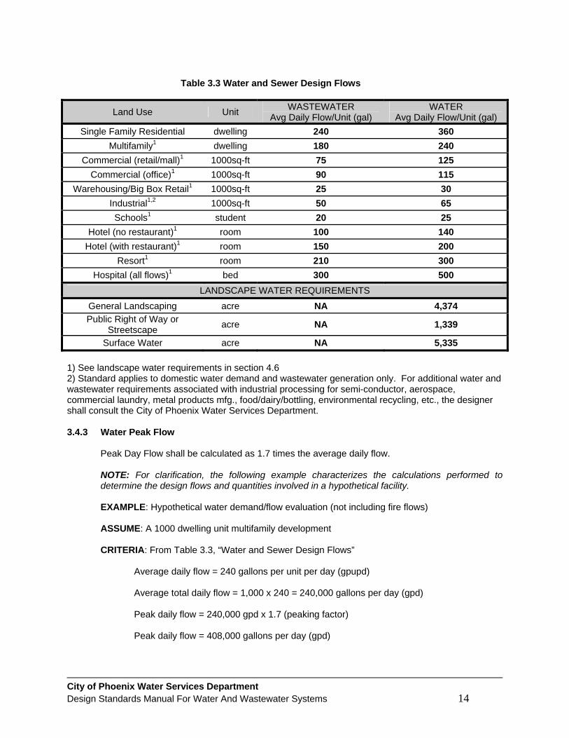
Table 3.3 shall be used to calculate both water and sewer design flows utilized in the preparation of engineering design reports, plans and specifications.
City of Phoenix Water Services Department Design Standards Manual For Water And Wastewater Systems 14
Table 3.3 Water and Sewer Design Flows
Land Use Unit WASTEWATER Avg Daily Flow/Unit (gal)
WATER Avg Daily Flow/Unit (gal)
Single Family Residential dwelling 240 360 Multifamily1 dwelling 180 240
Commercial (retail/mall)1 1000sq-ft 75 125 Commercial (office)1 1000sq-ft 90 115
Warehousing/Big Box Retail1 1000sq-ft 25 30 Industrial1,2 1000sq-ft 50 65 Schools1 student 20 25
Hotel (no restaurant)1 room 100 140 Hotel (with restaurant)1 room 150 200
Resort1 room 210 300 Hospital (all flows)1 bed 300 500
LANDSCAPE WATER REQUIREMENTS General Landscaping acre NA 4,374 Public Right of Way or
Streetscape acre NA 1,339
Surface Water acre NA 5,335 1) See landscape water requirements in section 4.6 2) Standard applies to domestic water demand and wastewater generation only. For additional water and wastewater requirements associated with industrial processing for semi-conductor, aerospace, commercial laundry, metal products mfg., food/dairy/bottling, environmental recycling, etc., the designer shall consult the City of Phoenix Water Services Department. 3.4.3 Water Peak Flow
Peak Day Flow shall be calculated as 1.7 times the average daily flow. NOTE: For clarification, the following example characterizes the calculations performed to determine the design flows and quantities involved in a hypothetical facility. EXAMPLE: Hypothetical water demand/flow evaluation (not including fire flows) ASSUME: A 1000 dwelling unit multifamily development CRITERIA: From Table 3.3, “Water and Sewer Design Flows”
Average daily flow = 240 gallons per unit per day (gpupd) Average total daily flow = 1,000 x 240 = 240,000 gallons per day (gpd) Peak daily flow = 240,000 gpd x 1.7 (peaking factor) Peak daily flow = 408,000 gallons per day (gpd)

City of Phoenix Water Services Department Design Standards Manual For Water And Wastewater Systems 15
3.4.4 Sewer Peak Flow
All gravity sewers, lift stations, and force mains shall be designed for peak flow conditions. Peak flow is calculated as the product of the peaking factor and the average daily flow. The peaking factor should be calculated from Harmon’s formula. Design Flow Equation Design Flow = Peak Flow = Q Peak = Q avg [1+14/ (4+ P)], Where P = Population/1,000

City of Phoenix Water Services Department Design Standards Manual For Water And Wastewater Systems 16
CHAPTER 4 WATER DISTRIBUTION AND TRANSMISSION SYSTEMS
4.1 WATER SYSTEM OVERVIEW 4.1.1 Pressure Zones
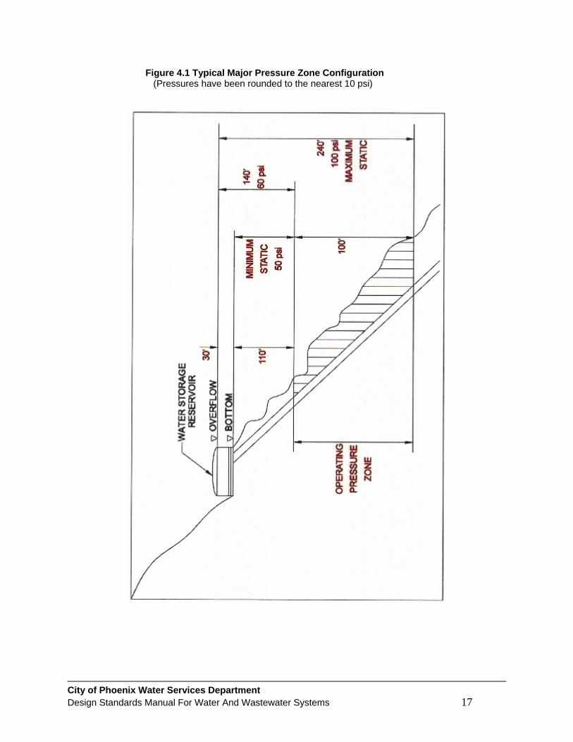
Approximately 90 operating pressure zones serve the municipal water distribution system for the City of Phoenix. These zones operate nominally within a static pressure range between 40 to 100 psi. With regards to typically high seasonal water demand variations among pressure zones with elevated storage, operating pressure fluctuations are normal. Information on pressure zones serving the various areas of the City can be obtained from the WSD. Figure 4.1, "Typical Major Pressure Zone Configuration", schematically shows a major pressure zone representing elevated storage. Not all pressure zones include elevated storage. Therefore, individual development design requirements may vary.
4.2 WATER MAIN DESIGN CRITERIA APPLICABLE TO BOTH DISTRIBUTION AND TRANSMISSION MAINS
4.2.1 Water Main Extensions
The water main extension policy of the City of Phoenix is contained in Article II, of Chapter 37 of the Phoenix City Code. As set forth in the Code, developers must pay all costs for constructing water mains necessary to afford adequate service during peak demands, including fire flow. Under certain circumstances, as described in Section 37-35 of the Code, repayment of the cost of “off-site” water mains (approach mains) may be available.
4.2.2 Water Main Classifications
For the purposes of this manual, all water mains in the City of Phoenix system that are 16 inches and larger in diameter are classified as transmission mains. All water mains 12 inches and smaller in diameter are classified as distribution mains. Exception: occasionally water mains 16 inches in diameter can be either depending on the design application. In some cases, development water demands, including fire flow may exceed the minimum pipe sized outlines in Chapter 37 of the Code. In these cases where the existing grid is not capable of providing adequate source water, a larger 16 inch main will be stipulated. This 16 inch main is then configured as a distribution main. The WSD will make this determination.
City of Phoenix Water Services Department Design Standards Manual For Water And Wastewater Systems 17
Figure 4.1 Typical Major Pressure Zone Configuration (Pressures have been rounded to the nearest 10 psi)

City of Phoenix Water Services Department Design Standards Manual For Water And Wastewater Systems 18
4.2.3 Water Main Design
Generally, water main design shall be based on peak day flow plus fire flow demands up to a maximum of 3,000 gpm. In some circumstances, the WSD may determine that larger or smaller water mains are required. Water mains shall be designed to maintain a pressure greater than or equal to 25 psi at a point of maximum fire draft, at a velocity of less than or equal to 10 fps. Furthermore, water mains shall be designed to maintain between 50 to 100 psi during peak hour flow at a flow velocity of less than or equal to 5 fps.
4.2.4 Fire Flow Demand
For fire flow demands, please refer to the current adopted City of Phoenix Fire Code.
4.2.5 Hydraulic Requirements
The Water Services Department (WSD) may require a hydraulic modeling analysis for a project in order to evaluate and properly develop the available water source. NOTE: Modeling may identify a requirement for a booster station, pressure reducing facility, etc. The WSD will make this determination.
4.2.6 Thrust Restraint for Distribution Mains
Joint restraint shall be used at all bends and fittings or where joint restraint devices are specified by the approved construction plan. Refer to MAG Standard Detail 303 and the City Supplements to MAG.
4.2.7 Corrosion Protection/Ductile Iron Pipe
Where indicated by soil testing or as directed by the WSD, ductile iron pipe mains shall be protected from exterior corrosion. This protection may consist of encasement in a polyethylene protective wrapping or other approved methods. Refer to the American Water Works Association corrosivity charts for more information.
4.2.8 Separation from Sanitary Sewer Mains
To minimize the potential for cross contamination, water and sewer mains shall meet the separation requirements described in AAC R18-4-502 and illustrated in MAG Standard Detail No. 404-1.
4.2.9 Separation from Sanitary Sewer Connections
Vertical clearance between water mains and sewer service connections: the water main shall not be less than 6 inches above the sewer service even if the sewer service connection is constructed with ductile iron pipe.
4.2.10 Separation from Storm Drains and Culverts
Water mains shall maintain 6 feet horizontal and 2 feet vertical exterior surface separation from storm drains and culverts. Water mains crossing less than 2 feet above a storm drain or culvert, but no closer than 12 inches shall have additional protection. Examples of additional protection are restrained joints, pipe casing, alternative piping materials, or as approved by the WSD.

City of Phoenix Water Services Department Design Standards Manual For Water And Wastewater Systems 19
4.2.11 Separation from Other Utilities
Water mains shall maintain a minimum 6 foot horizontal and 1 foot vertical separation to any underground dry utility. Any vertical separation between 1 foot and 2 feet shall be approved on a case by case basis by the plan reviewer or the construction inspector. Anything less than 1 foot vertical separation shall require approval through the technical appeal process.
4.2.12 Cross Connections and Backflow Prevention
No physical connection shall be allowed between potable and non-potable sources. Any connection is considered a cross connection. Specific provisions regarding cross connections and backflow prevention are available in the Development Services Department, Building and Safety. Refer to the adopted City of Phoenix Plumbing Code.
4.2.13 Shop Drawings
For pipe and appurtenances larger than 12 inch, shop drawings and technical data are required for approval. After engineer’s review and recommendation, shop drawings shall be submitted to Water Services Department for review and approval. A minimum of three copies of each shop drawing and product data shall be provided.
4.3 ADDITIONAL DESIGN CRITERIA ONLY APPLICABLE TO
DISTRIBUTION MAINS 4.3.1 General
Distribution mains are 6, 8, or 12 inches in diameter. As described in Section 4.2.2, 16 inch mains are occasionally considered distribution mains. No other pipe sizes are allowed to be constructed within the Phoenix water distribution grid. Project designs shall make every effort to loop water mains throughout the development to limit dead ends.
4.3.2 Water Plan Requirements - Check Lists
For preparation of private development water system plans that will become a part of the Phoenix water system, refer to the P&D website at the following link: http://www.phoenix.gov/development/siteandcivil/civil/index.html
4.3.3 Acceptable Pipe Materials
Distribution mains 6 inches through 16 inches in diameter shall be ductile iron pipe (DIP). The pipe shall conform to the MAG and City of Phoenix MAG supplement Specifications.
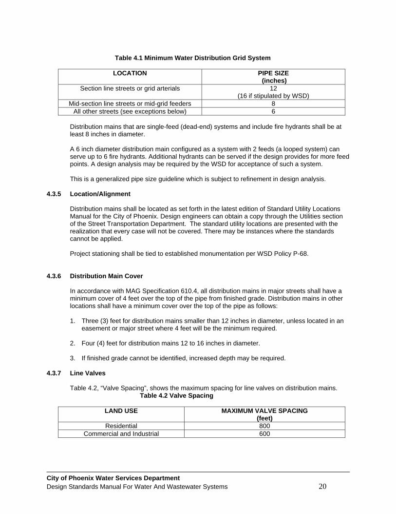
4.3.4 Pipe Sizing for Distribution Mains
The design engineer shall size all distribution system pipes and appurtenances in accordance with the provisions of this manual. Additionally, City Code 37-33(a) establishes a minimum water distribution master grid system for residential type development as indicated by Table 4.1, “Minimum Water Distribution Grid System”. For all other types of development, water mains are sized to meet fire flow requirements, or approved master plans, whichever is greater.
City of Phoenix Water Services Department Design Standards Manual For Water And Wastewater Systems 20
Table 4.1 Minimum Water Distribution Grid System
LOCATION PIPE SIZE
(inches) Section line streets or grid arterials 12
(16 if stipulated by WSD) Mid-section line streets or mid-grid feeders 8
All other streets (see exceptions below) 6
Distribution mains that are single-feed (dead-end) systems and include fire hydrants shall be at least 8 inches in diameter. A 6 inch diameter distribution main configured as a system with 2 feeds (a looped system) can serve up to 6 fire hydrants. Additional hydrants can be served if the design provides for more feed points. A design analysis may be required by the WSD for acceptance of such a system. This is a generalized pipe size guideline which is subject to refinement in design analysis.
4.3.5 Location/Alignment
Distribution mains shall be located as set forth in the latest edition of Standard Utility Locations Manual for the City of Phoenix. Design engineers can obtain a copy through the Utilities section of the Street Transportation Department. The standard utility locations are presented with the realization that every case will not be covered. There may be instances where the standards cannot be applied. Project stationing shall be tied to established monumentation per WSD Policy P-68.
4.3.6 Distribution Main Cover
In accordance with MAG Specification 610.4, all distribution mains in major streets shall have a minimum cover of 4 feet over the top of the pipe from finished grade. Distribution mains in other locations shall have a minimum cover over the top of the pipe as follows:
1. Three (3) feet for distribution mains smaller than 12 inches in diameter, unless located in an
easement or major street where 4 feet will be the minimum required.
2. Four (4) feet for distribution mains 12 to 16 inches in diameter.
3. If finished grade cannot be identified, increased depth may be required. 4.3.7 Line Valves
Table 4.2, “Valve Spacing”, shows the maximum spacing for line valves on distribution mains. Table 4.2 Valve Spacing
LAND USE MAXIMUM VALVE SPACING
(feet) Residential 800
Commercial and Industrial 600

City of Phoenix Water Services Department Design Standards Manual For Water And Wastewater Systems 21
In residential developments, valves shall be located so that a maximum of 30 single family dwelling units or a maximum of 5 valves are involved in a waterline shutdown. 1. A valve shall be located on each side of a canal, wash, railroad and freeway crossing.
2. Valves shall not be located in curbs, sidewalks, driveways, and valley gutters.
3. All valves shall conform to MAG Specification 610.6 and 630, including the C.O.P.
supplement thereto.
4. Valves shall be located at the point of curvature (PC) of the curb return at street intersections and aligned with a property or lot line in mid-block.
5. Valve boxes and covers shall be provided for all valves. 4.3.8 Service Connections and Meters on Distribution Water Mains 6 inches and Larger
Specific provisions for service connections and meters are contained in Article III and Article IV, Chapter 37 of the Phoenix City Code. A brief summary of Code provisions for the design engineer follows: 1. Where new mains are being installed by a developer, service connections will be installed by
the developer's contractor. With all service connections 3 inches and larger, the developer is responsible for providing the vault. Vault must be located in ROW, water easement, or PUE, as approved by the WSD. See vault detail W-500 on the WSD website at the following link: http://phoenix.gov/waterservices/design/engdetails/index.html
2. All new service connections on existing City water mains shall be installed by the WSD after all fees are paid. Contact P&D at 602-262-6551 for more information.
3. A water service line shall not be installed in a sewer trench with less than 6 feet of horizontal exterior surface clearance, however 3 feet with other water services and dry utilities is acceptable.
4. In accordance with Section 37-40 of the Code, every separate building supplied with City water must have its own separate service connection and meter. A single service line and a “Master Meter” can be used for two or more buildings located on the same lot or for apartment developments, trailer courts or similar projects covering one lot. In these “Master Meter” applications where an assured continuous supply must be maintained, the domestic development demand can be split and two meters may be used, each with its own service connection to the City main and then manifolded on the customer side of the meter. Beyond meeting the need to provide an uninterrupted supply to a development, the manifolding of more than 2 meters shall not be allowed.
5. The level of service impacts to existing customers and available resources shall be considered when selling new service connections and meters on existing mains. There is a limit to the level of service available, affected by competing adjacent property demands along a given water service main. New service connections shall be limited in size to 50% of the service main diameter. A new water main extension may be required when it has been determined by the WSD that existing main capacity has been exceeded.
6. When multiple distribution mains in the same pressure zone are adjacent to a development,
all service connections must be taken from the largest diameter main, or as approved by the WSD.
City of Phoenix Water Services Department Design Standards Manual For Water And Wastewater Systems 22
7. Where local static water pressure is in excess of 80 psi a private pressure regulator valve
shall be required on the customer side of the service meter. 4.3.9 Service Connections and Meters on Substandard Distribution Water Mains (smaller than 6
inches in diameter)
1. All development, excluding one single residence on a single lot as defined in 2 & 3 below, will not be allowed to purchase a new water service from a substandard waterline. In these cases, the developer will be required to comply with the requirements of City Code 37-33.
2. For a single residence on a single lot where there is a fire hydrant within 350 feet of the proposed construction. A service may be sold for the residence with the following stipulation: “The waterline that you have purchased a service from is considered substandard by City Code 37-33. A tap may not be able to be placed successfully on the line. The City will attempt to place a new service tap onto the substandard waterline. If a new service tap cannot be placed on the substandard waterline, then the applicant will be required to extend a new waterline to the property from the nearest non-substandard waterline (6 to 12 inches in diameter) in order to provide service to the residence.”
3. For a single residence on a single lot where there is not a fire hydrant within 350 feet of the proposed construction. The applicant will be required to contact a Fire Protection Engineer with the Phoenix Fire Department to discuss options. Options may include a main extension to bring a hydrant closer to the property, installing a residential sprinkler system which allows for a hydrant to be located up to 500 feet from the proposed construction, or obtaining a waiver. This is consistent with the Revised Fire Hydrant Location Requirements, April 2002, as adopted by the Development Advisory Board, and as written in this manual in section 4.8. Once the fire protection issue is resolved, a service may be sold for the residence with the stipulation defined in 2 above.
All other requirements of Chapter 37 of the Phoenix City Code and the Phoenix Plumbing Code shall apply.
4.3.10 Water Meters and Sizing Guidelines
UPC Section 610.1: The size of each water meter and each potable water supply pipe shall be based on the total demand and shall be determined according to the methods and procedures outlined in this section. The type of meter selected should be compatible with these meter types, Positive Displacement (PD), Compound (Comp) or Turbine (Turbo) meter. The following guidelines should be used. 1. Positive Displacement and Compound meters are designed to accommodate the wide range
of fluctuating demands associated with residential and commercial developments.
2. Turbine meters are designed to accommodate large demands within a narrow range of fluctuating flow as those associated with industrial type development. Also due to this characteristic, turbo meters have application for metered delivery of constant high flow rate demands associated with non pressure environments such as lake and pond fill lines during off peak hours.
Water meters will be sized in accordance with Table 4.3. The columns list the design allowable gallons per minute (gpm) or fixture units allowed for any given meter. Project designs which exceed the listed gpm unit values must be up-sized to the next larger meter.

City of Phoenix Water Services Department Design Standards Manual For Water And Wastewater Systems 23
Table 4.3 Water Meter Sizing
Column 1 Column 2 Column 3 Column 4 METER SIZE
AND DISCRIPTION
WSD & P&D DESIGN ALLOWABLE
(gpm)
MAXIMUM FLUSH TANK FIXTURE
UNITS
MAXIUM FLASH VALVE FIXTURE
UNITS 5/8” x 3/4” PD 15 21 0 3/4” x 3/4” PD 25 42 8 1” PD 40 86 28 1-1/2” PD 65 200 92 2” PD 100 380 245 2” Compound 128 522 416 3” Compound 250 1335 1335 4” Compound 400 2670 2670 6” Compound 800 6280 6280 8” Compound 1280 10,048 10,048
Use of turbo meters is limited as described in paragraph 2 on previous page.
2” Turbo 12 - - 3” Turbo 280 - - 4” Turbo 480 - - 6” Turbo 1000 - - 8” Turbo 2080 - - Notes for Table Use: 1. Use of water meters 6 inches and larger requires special advance consultation with the WSD
to determine availability, actual flow capacity, meter cost, and delivery schedule.
2. Column 2 is the design meter flow rate as determined by the Water Services and Development Services Departments.
3. Column 3 is the maximum number of fixture units permitted on a water distribution system when the plumbing fixtures are predominantly flush tank type water closets and urinals.
4. Column 4 is the maximum number of fixture units permitted on a water distribution system when the plumbing fixtures are predominantly flush valve type water fixture units.
5. Meter location must be out of traveled roadway/walk. Meter locations shall be easily accessible from a street.
6. Materials and installation for service lines shall conform to MAG Specification 631 and the Phoenix Supplement thereto. All service lines for meters 3 inches and larger shall be DIP. Service lines for meters less than 3 inches shall be Type “K” copper tubing.
7. Water meters servicing golf courses, lakes or any other continuous maxi-mum flow uses terminating at atmospheric pressure require special approval from the WSD. These installations require a flow control valve and/or a flow restriction device and may be limited to the use of reclaimed water.
8. All new taps for buildings including all single family residential lots shall be a minimum of 1
inch in size. New ¾ inch taps may be installed for landscape irrigation or other approved special uses only.

City of Phoenix Water Services Department Design Standards Manual For Water And Wastewater Systems 24
9. A separate landscape irrigation tap and meter is required for irrigated areas over 10,000 square feet, or 1,000 gallons or more per day. (Phoenix City Code Section 37-53 (b) (1)).
NOTE: Refer to Section 4.6, “Irrigation Systems and Water Features”. 10. Combination Fire/Domestic/Landscape meters are prohibited. (Phoenix City Code Section
37-73 & UFC 1001.6.1). Each demand requires a separate service connection.
11. Development Occupation Fees (DOF) applies to all developments requiring water and/or sewer. Single–family residential properties are charged a flat fee regardless of size of water meter. For multi-family uses, fees are charged per unit. For all other uses, fees are based on the water meter size, not the tap size. DOF fees are required per Phoenix City Code Sections 19 A-D.
12. Water Resource Acquisition Fees (WRA) applies to all developments requiring a water service. The fees vary by area and are based on the water meter size, not the tap size. WRA Fees are required per Phoenix City Code Section 30.
13. Impact fees vary by area and are based on the water meter size, not the tap size. Impact Fees are required per Phoenix City Code Section 19.
Questions about fixture unit calculations should be addressed to the following:
For single family residential: Planning and Development Services Residential Permit Counter, (602) 262-7884. For all other uses: Planning and Development Services Regional Teams, (602)495-0258.
Questions about water meter sales, taps, service fees and installation fees should be addressed to the Planning and Development Services Engineering Counter (602) 262-6551.
4.4 ADDITIONAL DESIGN CRITERIA ONLY APPLICABLE TO
TRANSMISSION MAINS 4.4.1 General
Transmission water mains are typically 16 inches in diameter and larger. Transmission mains must have a parallel distribution main, diameter to be determined by the WSD, in order to support the local water demand, including fire flow requirement. Refer to the WSD, “Standard Details for 16 inch and Larger Pipe” to supplement this design section. All ties, outlets and appurtenances shall be made by a flanged connection and shall include a valve with at least one flanged side at that point of connection for independent control. NOTE: Service connections will not be allowed on transmission mains.
4.4.2 Acceptable Pipe Materials
Transmission mains 16 inches in diameter shall be ductile iron pipe (DIP). Transmission mains 16 inches through 42 inches in diameter regardless of location shall be DIP, concrete cylinder pipe (CCP), or steel cylinder pipe. Mains 48 inches in diameter and larger shall be DIP, pre-stressed concrete cylinder pipe (PCCP), or steel cylinder pipe. The pipe shall conform to the applicable MAG specifications and the City of Phoenix Supplement thereto.

City of Phoenix Water Services Department Design Standards Manual For Water And Wastewater Systems 25
4.4.3 Pipe Sizing for Transmission Mains
Transmission mains shall be sized to carry the designed peak flow required including fire flow without exceeding the velocities or headlosses shown below. Table 4.4, “Allowable Velocity/Headloss”, shows specific requirements for transmission mains.
Table 4.4 Allowable Velocity/Headloss
PIPE SIZE (inches)
MAXIMUM ALLOWABLE VELOCITY
(fps)
MAXIMUM ALLOWABLE HEADLOSS (ft/1000 ft)
16 5 6.06 20 5 4.66
24 and larger 5 Varies* *To be determined by the Water Services Department. NOTE: The above table is based on a Hazen-Williams pipe roughness coefficient of C = 120
4.4.4 Location/Alignment
Transmission mains shall be located within rights-of-way as set forth in the latest edition of Standard Utility Locations for the City of Phoenix or as otherwise directed. A minimum 6 foot and 2 foot vertical exterior surface separation from any parallel underground utility is required. In all cases, a utility conflict review is required and requirements will be modified depending on the condition of the soils and any other factors that may adversely affect the project design. Project stationing shall be tied to established monumentation per WSD Policy P-68. Vertical alignment must be carefully considered in the design of transmission mains. A profile shall be provided for all transmission main designs. 1. To facilitate City review of a proposed main, a profile of the entire main shall be provided on a
single sheet in condensed form.
2. Line segments shall be set at a constant slope.
3. Design of the main shall provide for a minimum number of high and low points consistent with economic feasibility.
4.4.5 Cover
Minimum cover from finished grade to top of exterior surface of pipe shall begin at 6.5 feet for a 16 inch water line, and depending on design considerations, will generally range from 6.5 feet to 8 feet. If finished grade cannot be identified, increased depth may be required.
4.4.6 Line Valves
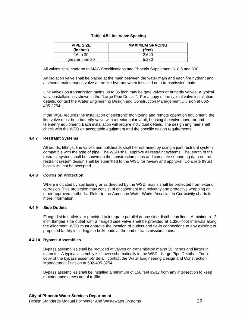
Table 4.5, “Line Valve Spacing”, shows the maximum spacing for line valves on transmission mains.
City of Phoenix Water Services Department Design Standards Manual For Water And Wastewater Systems 26
Table 4.5 Line Valve Spacing
PIPE SIZE (inches)
MAXIMUM SPACING (feet)
16 to 30 2,640 greater than 30 5,280
All valves shall conform to MAG Specifications and Phoenix Supplement 610.6 and 630.
An isolation valve shall be placed at the main between the water main and each fire hydrant and a second maintenance valve at the fire hydrant when installed on a transmission main. Line valves on transmission mains up to 36 inch may be gate valves or butterfly valves. A typical valve installation is shown in the “Large Pipe Details”. For a copy of the typical valve installation details, contact the Water Engineering Design and Construction Management Division at 602-495-3754. If the WSD requires the installation of electronic monitoring and remote operation equipment, the line valve must be a butterfly valve with a rectangular vault, housing the valve operator and telemetry equipment. Each installation will require individual details. The design engineer shall check with the WSD on acceptable equipment and the specific design requirements.
4.4.7 Restraint Systems
All bends, fittings, line valves and bulkheads shall be restrained by using a joint restraint system compatible with the type of pipe. The WSD shall approve all restraint systems. The length of the restraint system shall be shown on the construction plans and complete supporting data on the restraint system design shall be submitted to the WSD for review and approval. Concrete thrust blocks will not be accepted.
4.4.8 Corrosion Protection
Where indicated by soil testing or as directed by the WSD, mains shall be protected from exterior corrosion. This protection may consist of encasement in a polyethylene protective wrapping or other approved methods. Refer to the American Water Works Association Corrosivity charts for more information.
4.4.9 Side Outlets
Flanged side outlets are provided to integrate parallel or crossing distribution lines. A minimum 12 inch flanged side outlet with a flanged side valve shall be provided at 1,320- foot intervals along the alignment. WSD must approve the location of outlets and tie-in connections to any existing or proposed facility including the bulkheads at the end of transmission mains.
4.4.10 Bypass Assemblies
Bypass assemblies shall be provided at valves on transmission mains 16 inches and larger in diameter. A typical assembly is shown schematically in the WSD, “Large Pipe Details”. For a copy of the bypass assembly detail, contact the Water Engineering Design and Construction Management Division at 602-495-3754. Bypass assemblies shall be installed a minimum of 150 feet away from any intersection to keep maintenance crews out of traffic.
City of Phoenix Water Services Department Design Standards Manual For Water And Wastewater Systems 27
Transmission mains between valves shall be treated as an independent unit with provisions for dewatering, filling, removing air and adding air as appropriate for the transmission main construction and maintenance. A bottom tangent flanged outlet shall be provided at all profile low points and a top tangent flanged outlet shall be provided at all profile high points, in all transmission mains.
4.4.11 Air/Vacuum Valve Assemblies
All air/vacuum valve assemblies for transmission mains require individual approval by the WSD. Air/vacuum relief valve assemblies shall be installed at high points in the transmission main at locations approved by the WSD. Air/Vacuum valve assemblies are to be used only when it is determined that a fire hydrant is not appropriate.
4.4.12 Access Outlets for 42 inch Mains and Larger Access outlet with manhole as shown in WSD “Large Pipe Details” shall be installed on 42 inch diameter and larger transmission mains on each side of a line valves and shall not exceed 2,600 feet unless otherwise approved. For a copy of the access outlet detail, contact the Water Engineering Design and Construction Management Division at 602-495-3754.
4.4.13 Use of Fire Hydrants and Placement
In water mains 16 inches and larger a fire hydrant shall be placed at the high point and/or low point of the profile to permit air release and de-watering when applicable.
4.4.14 Testing and Final Acceptance
The construction project is functional only after demonstrating the completion of pressure testing, bacteriological testing and final inspections. Then an acceptable flushing schedule and chlorine residual monitoring plan must be prepared by the design engineer to maintain and demonstrate an acceptable level of turnover during the early period of new project operation. Upon substantial completion, the start-up and commissioning period is ready to begin. The start-up details and duration of commissioning shall be identified early on and listed in the project scope of work by the design engineer.
4.4.15 Transmission Main Plan Requirements - Check Lists
For preparation of private development water system plans that will become a part of the Phoenix water system, refer to the Water Transmission Plan Checklist. For preparation of Capital Improvement Program (CIP) water system plans, refer to the above checklist, along with Policy P-85. The checklist and the policy are available on the WSD website at the following link: http://phoenix.gov/waterservices/design/engpolicies/index.html
4.5 FIRE LINE SYSTEMS 4.5.1 General
A fire line is a private pipe system connected directly to the City water system. A fire line, by the nature of its function and use, is susceptible to backflow. Consequently, it is subject to the requirements for backflow prevention. Above ground installation of backflow prevention devices shall conform to the requirements as written in City Ordinance Chapter 37 article XII.

City of Phoenix Water Services Department Design Standards Manual For Water And Wastewater Systems 28
A fire line shall be utilized for fire protection only and shall serve only a single property. Typically, a fire line is a connection for on-site private hydrants or an interior fire sprinkler system for a building. The Water Services Department’s (WSD) review and approval interest is limited only to that portion to be constructed in the ROW or water easement.
4.5.2 Acceptable Pipe Materials
All fire line installations shall conform to the applicable MAG Specifications and Details and the Phoenix Supplements thereto. The fire line shall be constructed of ductile iron pipe from the control valve at the water main to the farther of the property line, backflow prevention device or detector check valve.
4.5.3 Design Requirements
All fire line installations shall conform to the City Fire Code and the following requirements of the WSD. 1. The minimum size fire line connection shall be 4 inches. Smaller fire line sizes are approved
on a case-by-case basis.
2. Every fire line shall have a control valve at the connection to the City water main.
3. Backflow prevention devices are required per the City of Phoenix Adopted Plumbing Code, as well as City Code Chapter 37 article XII.
4.5.4 Fire Line Plan Requirements - Check List
For preparation of fire line plans that will become a part of the City water system, the design engineer is referred to the Planning and Development Services Department (P&D) website. A checklist for preparing the fire line plan is available at the following link: http://www.phoenix.gov/development/siteandcivil/civil/index.html
4.5.5 Plans Processing Guidelines
All technical and engineering plans relating to projects subject to the Development Review process shall be submitted to the P&D for review evaluation and approval. Other technical and engineering plans relating to City projects under the jurisdiction of the WSD shall be submitted to the P&D as directed for review evaluation and processing. Plans for fire line systems outside of the City limits showing a fire line connected to the City water system shall be submitted to and approved by the WSD. The plans shall be prepared in accordance with applicable City codes and procedures. The plans must have the approval of the appropriate jurisdictional fire agency prior to WSD approval. A plan review fee is charged by the City for review and processing. The jurisdictional agency having authority over construction activity within their public rights of way will have additional plan approval requirements and shall be contacted for their plan processing procedures. Design approval and construction permits shall be obtained from all agencies involved.

City of Phoenix Water Services Department Design Standards Manual For Water And Wastewater Systems 29
4.6 IRRIGATION SYSTEMS AND WATER FEATURES 4.6.1 General
An irrigation system is a private pipe system connected directly to the City water system through a metered service connection. An irrigation line is utilized for irrigation only.
4.6.2 Backflow Prevention
Backflow prevention assemblies will be required per City of Phoenix Adopted Plumbing Code. 4.6.3 Service Connections/Meters
In accordance with Section 37-53 of the Phoenix City Code, a separate irrigation meter is required for irrigation watering within landscaped areas over 10,000 square feet, and/or for all water features (as defined in Section 37-111) having a maximum daily consumptive use of 1,000-gallons or more per day. Installation of irrigation meters requires a flow control valve and/or a flow restriction device. The WSD shall make that determination.
4.6.4 Landscape Water Permit
In accordance with Section 37-113 of the Phoenix City Code, a Landscape Water Permit is required for irrigation of large turf-related facilities. A large turf-related facility is defined as a site that has 5 or more acres of turf or high-water-use landscaping. Schools, parks, cemeteries, and golf courses typically fall into this category. A permit application may be obtained from the WSD Water Resources Development Planning - Water Conservation Office. A permit may be issued after a “Water Conservation and Non-Potable Water Use Plan” is submitted and approved by the WSD. A condition of the permit will be that non-potable water must be used for irrigation unless the cost of providing non-potable water would be prohibitively high to the developer or WSD. The WSD shall make that determination. The developer will need to enter into a contract for the sale and use of non-potable water before the service connection can be approved.
4.7 WATER ABANDONMENT 4.7.1 Plan Requirements Checklist
In order to prepare a water abandonment plan for removal or abandonment of an existing water main in the City of Phoenix system, the design engineer is directed to the WSD website under the title “Water/Sewer Abandonment Plan”. http://phoenix.gov/WATER/desstand.html
4.7.2 Abandonment Methods
There are three approved methods of abandoning water and sewer lines in public ROW and easements: 1. Total removal of pipe. 2. Crush pipe in place by mechanical means. This cannot be applied to asbestos cement pipe.

City of Phoenix Water Services Department Design Standards Manual For Water And Wastewater Systems 30
3. Leave pipe in place and fill with low strength grout.
No other methods are acceptable.
4.8 FIRE HYDRANT REQUIREMENTS 4.8.1 General Location and Design Requirements
Fire hydrants must be located where they can be quickly found and easily used by fire engines arriving at an incident. Standardized location criteria are based on predictability, visibility, unobstructed accessibility, the type of development, Fire Department tactical needs, and the expected route fire engines will travel to the site. Determining proper fire hydrant location requires the application of engineering judgment and common sense to the specific conditions found in each project. Minor variances in the locations or spacing of individual hydrants may be approved provided the functional intent of these design standards is achieved. 1. Locate fire hydrants on the right hand (passenger) side of streets, intersections, driveways
and fire lanes within 6 feet of the curb. This location matches the hose connections on fire pumpers and allows the hydrant to be connected in the quickest, most efficient manner.
2. Locate fire hydrants where they are readily visible by fire engines traveling along the street or approaching on intersecting streets. Never obscure or obstruct hydrants behind fences, gates, walls or landscaping.
3. Existing fire hydrants on major streets, collector streets, or any other street having 4 or more lanes of traffic, that are not divided by raised median islands can be included in the coverage analysis. If those streets classes are divided by raised median islands then the existing hydrant can only be included in the coverage analysis if it is located on the same side as the new development.
4. When designing a fire hydrant layout, the first hydrant is to be located at street intersections and at the main entrance into a subdivision, apartment complex, or commercial development. Additional hydrants must then be spaced approximately evenly between these points at a distance not to exceed the maximum spacing between hydrants. Spacing is measured along the route of travel of a fire engine.
5. Fire hydrants separated from a subdivision, building or other development by continuous fence, wall or other obstruction cannot be counted as providing protection to that subdivision or development. For example, where a residential subdivision is separated from its perimeter street by a continuous fence, fire hydrants must be installed along the perimeter street (City Code Section 37-33) and internally along the streets within the subdivision, with hydrant spacing measured along the route of travel of the fire engine, not over the fence.
6. A fire hydrant shall be placed within 30 feet of the end of all dead end water mains greater than 100 feet to facilitate flushing and maintenance of the water main (including cul-de-sacs).
7. Fire Hydrants shall not be placed within 3 feet of an above ground obstruction and must
maintain 15 inches of clearance between the ground and the lowest hydrant outlet cap. If required by the WSD, hydrants shall be located within water easements providing at least 6-feet of clearance on all sides of the hydrant, including protective bollards as directed.

City of Phoenix Water Services Department Design Standards Manual For Water And Wastewater Systems 31
8. Existing fire hydrants determined to be on a transmission main are intended for air relief, dewatering and maintenance purposes and can be scheduled out of service periodically. Therefore, these fire hydrants shall not be included in the total count to meet a developer’s fire hydrant coverage requirement. The bonnets on these hydrants are painted black.
9. All fire hydrants shall be of the dry barrel type conforming to MAG Specifications 610.8, 756 and the Phoenix MAG Supplement.
10. Fire hydrants shall be located along streets in accordance with the City of Phoenix supplement to MAG Detail P-1362.
4.8.1 Residential Subdivision Hydrant Location Standards
Fire hydrant locations will be reviewed and approved as part of the subdivision approval process. Follow the General Location and Design Requirements as stated in 4.8.1 and: 1. Start by locating a fire hydrant at the intersection of each public and /or private street
entrance into the subdivision unless an existing fire hydrant meets spacing requirements.
2. Then space additional fire hydrants approximately 500 feet apart along all public and/or private streets within the subdivision and along all perimeter streets.
3. For cul-de-sacs: a) No hydrant required on the cul-de-sac if all houses are within 350 feet of a hydrant on the
street servicing the cul-de-sac and the dead end line within the cul-de-sac is less than 100 feet.
b) If all houses are NOT within 350 feet of the hydrant on the street serving the cul-de-sac and the dead end line within the cul-de-sac is less than 100 feet then provide a hydrant at the intersection entrance into the cul-de-sac.
c) If dead end line length is such that additional hydrants are required, a hydrant shall be placed as close as possible to 30 feet from the end of the main.
4. For cluster home developments:
a) Fire hydrant locations per ordinance requirements
4.8.1 Commercial and Multi-Family Hydrant Location Standards
Fire hydrant locations will be reviewed and approved as part of the site plan/building permit approval process. Provide a site plan showing all existing and proposed fire hydrant locations, all designated fire lanes, and all fire department connections (FDC’s) for building standpipe or sprinkler systems. Whenever possible hydrants shall be setback at least 40 feet from the building. Follow the General Location and Design Requirements as stated in 4.8.1 and: 1. First, determine whether new fire hydrants are needed or not. New hydrants are not needed
if existing hydrants are close enough to provide the required coverage: a) Within 350 feet of the most remote building corner or the most remote hazard on site,
measured as the hose lays along designated fire lanes or other clear access routes (within 500 feet of the most remote corner of fire sprinklered buildings)
b) Within 200 feet of all Fire Department connections (FDC’s) for sprinkler and standpipe systems.
If existing fire hydrants do not provide the required coverage, new hydrants must be added as follows:

City of Phoenix Water Services Department Design Standards Manual For Water And Wastewater Systems 32
2. Start by locating a fire hydrant at the main entrance (driveway) into the development, and at
other entrances identified as fire apparatus access roads (fire lanes).
3. Next locate a fire hydrant within 200 feet of all Fire Department connections (FDC’s) and standpipe inlets on buildings, but not closer than 40 feet to the building.
4. Then space additional hydrants approximately 300 feet apart between the above hydrants
along all public roads and along all designated fire lanes. 4.8.2 Private Fire Hydrants
Private hydrants are those hydrants located on private property and/or connected to any water line not owned and maintained by the city Water Services Department. Private fire hydrants shall have their bonnets painted reflective white to identify them as privately owned and maintained. The property owner is responsible for maintaining all private fire lines and private fire hydrants in working order at all times.
4.8.5 Maximum fire Hydrant Spacing
Table 4.6, “Fire Hydrant Spacing”, shows the maximum spacing for fire hydrants. Spacing distance shall be measured along the centerline of the street or route, which the fire truck will most likely travel. Table 4.6 Fire Hydrant Spacing
LAND USE SPACING REQUIREMENTS FIRE HYDRANT MAXIMUM
SPACING (feet)
Single Family Residential 500 Two Story Townhouses and Apartments 300
Commercial and Industrial (including Shopping Centers) 300 Offsite main extensions adjacent to undeveloped property 1000 or as required by WSD
Cul de Sacs Same as above, to include hydrant within 30 feet of pipe end
4.8.6 Fire Hydrant Relocations
In the design phase of projects, every attempt should be made to locate driveways outside of existing fire hydrant locations. In the event that a hydrant must be relocated, the relocation shall be in accordance with COP Supplement to MAG detail, P1344, which requires that the existing service line and valve be cut and removed from the existing water main, and a new section of pipe installed with a flexible coupling. A new fire hydrant service line shall be installed perpendicular to the new hydrant location.
In circumstances were the relocation of the existing hydrant would be 5 feet or less in either side to side direction, the WSD will allow a 90 degree bend be placed on the existing hydrant service line, and the hydrant to be relocated. Hydrant relocations with a 90 degree bend will only be allowed up to a maximum distance of 5 feet.

City of Phoenix Water Services Department Design Standards Manual For Water And Wastewater Systems 33
CHAPTER 5 WASTEWATER COLLECTION SYSTEM
5.1 GENERAL REQUIREMENTS
NOTE: Any and all more stringent requirements by Federal, State, County or local codes or ordinances shall take precedence.
5.1.1 Arizona Aquifer Protection Permit Requirements
The design of sewage collection systems shall conform to the requirements of the Aquifer Protection Permit General Permit rules in Arizona Administrative Code Title 18, Chapter 9. An Application for Approval to Construct and/or Notice of Intent to Discharge shall be submitted in accordance with AAC R18-9-A301(B) and E301(C). An Approval to Construct and/or Provisional Verification of General Permit Conformance shall be issued prior to commencing construction. Approval to Construct and/or Provisional Verification of General Permit Conformance include, but are not limited to, the following requirements: 1. Engineer’s Design Report.
2. Complete Construction-Ready Design Plans.
3. Specifications (CIP projects).
4. All other relevant information to verify that the facility conforms to the terms of the 4.01
General Permit. The design report, plans and specifications shall be signed and sealed by an Arizona Registered Professional Civil/Environmental Engineer. The sewage collection system shall not be placed in service until an Approval of Construction and/or Verification of General Permit Conformance has been issued. Approval of Construction and/or Verification of General Permit Conformance includes, but is not limited to, the following requirements: 1. An Engineer’s Certificate of Completion sealed and signed by an Arizona Registered
Professional Civil/Environmental Engineer, attesting that the sewers have been constructed to the requirements of AAC R18-9-A301.
2. As-built drawings, with each changed sheet sealed and signed by an Arizona Registered Professional Civil/Environmental Engineer, are submitted to the City of Phoenix, Water Services Department.
3. Satisfactory test results from deflection, leakage, and uniform slope testing are confirmed by the City of Phoenix.
4. All other relevant information to verify that the facility conforms to the terms of the 4.01 General Permit.

City of Phoenix Water Services Department Design Standards Manual For Water And Wastewater Systems 34
5.1.2 Maricopa County Health Code Requirements
Sewage collection systems shall conform to the requirements of the Maricopa County Health Code. Sewage collection system projects to be installed as part of the City’s CIP and projects to be constructed by private developers with City financial contribution shall be required to have plans approved and receive the certificates of approval and verifications of general permit conformance described above by the Maricopa County Department of Environmental Services.
5.1.3 City Code Requirements
Sewage collection systems shall comply with the requirements of Chapter 28 of the Phoenix City Code. The sewer line extension policy of the City of Phoenix is contained in Article III of Chapter 28 of the Phoenix City Code. Developers shall pay all costs for constructing all elements of the public wastewater system authorized by the City. Under certain circumstances as described in Section 28-23 of the Code repayment of the cost of "off-site" sewer lines may be available. Sewer extensions shall be designed for projected flows even when the diameter of the receiving sewer is less than the diameter of the proposed extension at a manhole with special consideration of an appropriate flow channel to minimize turbulence when there is a change in sewer size. A relief sewer may be planned in the future.
5.2 GRAVITY SANITARY SEWER LINES 5.2.1 General
The design and construction of gravity sanitary sewers in the City of Phoenix shall conform to the most current of the following publications: 1. Uniform Standard Specifications and details for Public Works Construction sponsored and
distributed by the Maricopa Association of Governments (MAG) and the City of Phoenix Supplement thereto, available at the following link:
http://www.mag.maricopa.gov/publications.cms
2. Arizona Department of Environmental Quality Aquifer Protection Permit Rules in Arizona Administrative Code Title 18, Chapter 9, located at the following link:
http://www.azdeq.gov/environ/water/permits/app.html
3. Maricopa County Health Code available at the following link:
http://www.maricopa.gov/EnvSvc/AboutUs/HealthCode.aspx
4. The standard specifications and details of the Water Services Department and design standards set forth in this manual, available at the following link:
http://www.phoenix.gov/waterservices/design/index.html

City of Phoenix Water Services Department Design Standards Manual For Water And Wastewater Systems 35
5.2.2 Acceptable Pipe Materials
Gravity sewer lines shall be either reinforced concrete pipe (RCP), ductile iron pipe (DIP) or vitrified clay pipe (VCP) as indicated below. Other materials may be approved on a case by case basis as approved by the WSD. The pipe shall conform to the applicable specifications as follows: 1. Reinforced Concrete Pipe and fittings: MAG Specifications and the Phoenix Supplement
Sections 735 and 741. Reinforced concrete pipes shall be PVC lined. RCP may be used for sewer lines 30 inches in diameter and larger.
2. Ductile Iron Pipe and fittings: MAG Specifications and the Phoenix Supplement Section 750. DIP may be used for sewer lines 8 inches through 54 inches in diameter. When DIP is used it shall be lined with Protecto 401 ceramic epoxy.
3. Vitrified Clay Pipe and Fittings: MAG Specifications and the Phoenix Supplement Section 743. Vitrified clay pipe may be used for sewer lines 8 inches through 42 inches in diameter.
5.2.3 Pipe Sizing
Gravity sewer lines shall be sized to accommodate the peak design flow subject to the following limitations: 1. The d/D ratio for gravity sewer pipes shall be no greater than 0.75 at the peak flow condition.
2. Minimum pipe size shall be 8 inches.
5.2.4 Slope
Gravity sewers shall be designed and constructed to provide mean velocities of not less than the velocities shown in Table 5.1, based on Manning’s formula, flowing full, and using an “n” value of 0.013. The minimum slopes required to maintain the minimum mean velocity are shown in Table 5.1. Designers shall minimize grade changes to be uniform throughout the entire pipeline project as well as from manhole to manhole. The WSD will not permit the use of larger pipe diameters than required to carry the peak flow in order to reduce the slope.
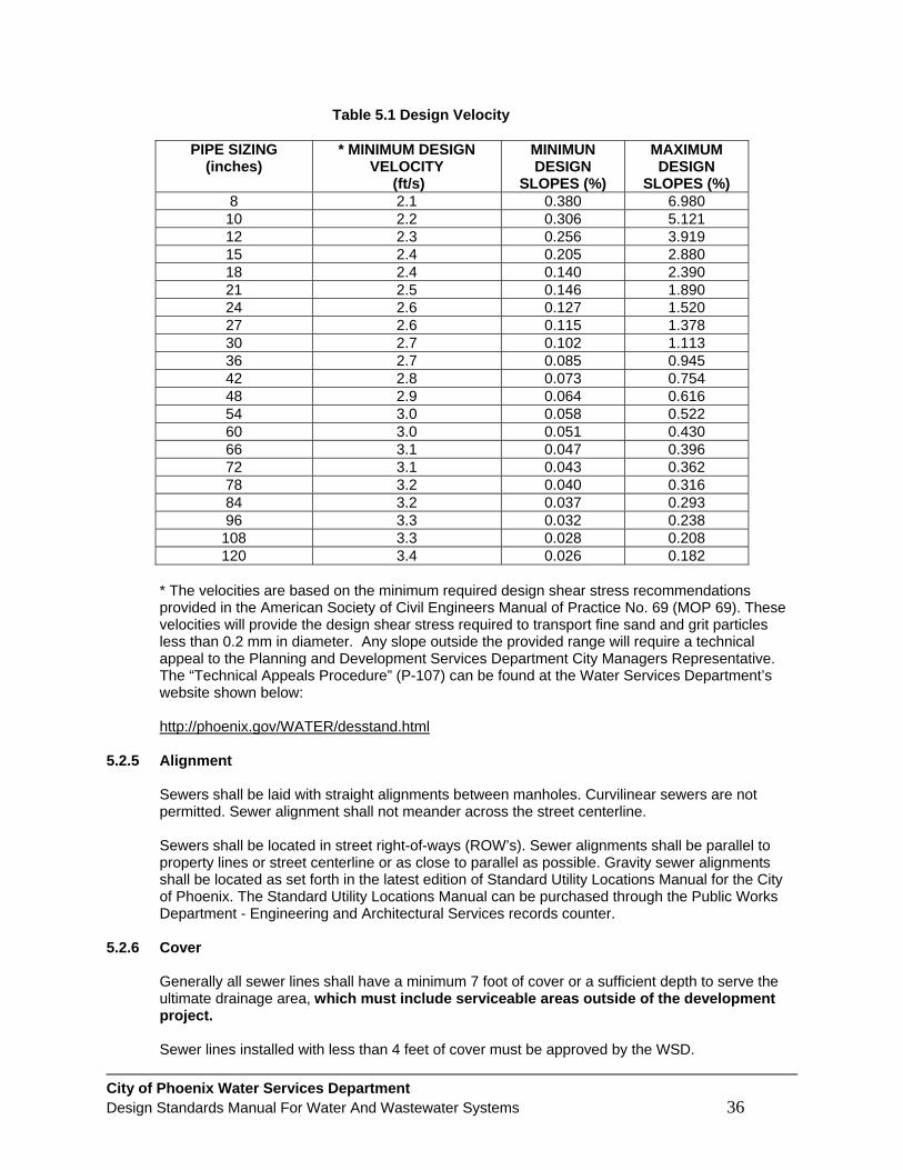
City of Phoenix Water Services Department Design Standards Manual For Water And Wastewater Systems 36
Table 5.1 Design Velocity
PIPE SIZING (inches)
* MINIMUM DESIGN VELOCITY
(ft/s)
MINIMUN DESIGN
SLOPES (%)
MAXIMUM DESIGN
SLOPES (%) 8 2.1 0.380 6.980 10 2.2 0.306 5.121 12 2.3 0.256 3.919 15 2.4 0.205 2.880 18 2.4 0.140 2.390 21 2.5 0.146 1.890 24 2.6 0.127 1.520 27 2.6 0.115 1.378 30 2.7 0.102 1.113 36 2.7 0.085 0.945 42 2.8 0.073 0.754 48 2.9 0.064 0.616 54 3.0 0.058 0.522 60 3.0 0.051 0.430 66 3.1 0.047 0.396 72 3.1 0.043 0.362 78 3.2 0.040 0.316 84 3.2 0.037 0.293 96 3.3 0.032 0.238
108 3.3 0.028 0.208 120 3.4 0.026 0.182
* The velocities are based on the minimum required design shear stress recommendations provided in the American Society of Civil Engineers Manual of Practice No. 69 (MOP 69). These velocities will provide the design shear stress required to transport fine sand and grit particles less than 0.2 mm in diameter. Any slope outside the provided range will require a technical appeal to the Planning and Development Services Department City Managers Representative. The “Technical Appeals Procedure” (P-107) can be found at the Water Services Department’s website shown below: http://phoenix.gov/WATER/desstand.html
5.2.5 Alignment
Sewers shall be laid with straight alignments between manholes. Curvilinear sewers are not permitted. Sewer alignment shall not meander across the street centerline. Sewers shall be located in street right-of-ways (ROW’s). Sewer alignments shall be parallel to property lines or street centerline or as close to parallel as possible. Gravity sewer alignments shall be located as set forth in the latest edition of Standard Utility Locations Manual for the City of Phoenix. The Standard Utility Locations Manual can be purchased through the Public Works Department - Engineering and Architectural Services records counter.
5.2.6 Cover
Generally all sewer lines shall have a minimum 7 foot of cover or a sufficient depth to serve the ultimate drainage area, which must include serviceable areas outside of the development project. Sewer lines installed with less than 4 feet of cover must be approved by the WSD.
City of Phoenix Water Services Department Design Standards Manual For Water And Wastewater Systems 37
Sewer lines constructed in washes and floodways shall have their crowns at least 2 feet below the 100 year storm scour depth and shall be constructed with DIP. The DIP shall extend a minimum of 10 feet each side of the 100 year storm scouring, which would be manhole to manhole.
5.2.7 Sewer Main Connections at Manholes
There shall be no more than 4 connections at a manhole. At manhole connections, the angle between the upstream pipe and the downstream pipe shall conform to the following guidelines: 1. Sewer mains 15 inches and larger in diameter shall not change flow direction more than 45
degrees in 1 manhole. Two (2) manholes shall be constructed to change flow direction more than 45 degrees and up to 90 degrees.
2. Sewer mains smaller than 15 inches in diameter shall intersect with man-holes maintaining a minimum of 90 degrees to the downstream pipe.
The upstream pipe shall be the same or smaller diameter than the downstream pipe and shall not have its crown lower than the crown of the downstream pipe. Where local sewage collection systems connect to interceptor sewers, the invert of the intersecting pipe shall be at or above the crown elevation of the downstream pipe. Intersecting pipes shall be of equal or smaller diameter than the downstream pipe. Typically, inverts through manholes and junction boxes shall be designed to maintain the energy gradient across the structure. Manholes and junction boxes having lines intersecting at 45 to 90 degrees shall have a minimum 0.10 foot drop across the structure.
5.2.8 Cross Connections Prohibited
There shall be no physical connections between a public or private potable water supply system and a sewer, or appurtenance thereto which would permit the passage of any wastewater or polluted water into the potable supply. No water pipe shall pass through or come into contact with any part of a sewer manhole.
5.2.9 Separation from Water Mains
To minimize the potential for cross contamination, water and sewer lines shall meet the separation requirements described and illustrated in MAG Standard Detail No. 404-1 with the following supplemental requirements: 1. Vertical clearance between water mains and gravity sanitary sewer mains: the water main
shall not be less than 12 inches above the sanitary sewer main, even if the sewer main is constructed with ductile iron pipe in accordance with Note 3B in MAG Standard Detail No. 404-1.
2. Vertical clearance between water mains and sewer service connections: the water main shall not be less than 6-inches above the sewer service.
3. Horizontal clearance between sanitary sewers and water mains shall be 6 feet.
Note: All clearance measurements shall be from outside edge of pipe to outside edge of pipe.

City of Phoenix Water Services Department Design Standards Manual For Water And Wastewater Systems 38
5.2.10 Separation from Water Supply System Structures
While no general statement can be made to cover all conditions, it is generally recognized that sewers shall meet the requirements of the appropriate reviewing agency with respect to minimum distances from public water supply wells or other water supply sources and structures. All existing waterworks units, such as basins, wells, or other treatment units, within 200 feet of the proposed sewer shall be shown on the plans.
5.2.11 Separation from Storm Drains and Culverts
For purposes of separation requirements, storm sewers are treated as sanitary sewers. Therefore, separation requirements are the same as sewer to sewer separation which is 3 feet horizontal and 6 inch vertical, or as approved by the WSD.
5.2.12 Separation from Other Utilities
Sewer mains shall maintain a minimum 6 feet horizontal separation and 2 feet vertical separation to any underground utility. Any vertical separation between 1 foot and 2 feet shall be approved on a case by case basis by the plan reviewer or the construction inspector. Anything less than 1 foot vertical separation shall require approval through the technical appeal process.
5.2.13 Buoyancy
Buoyancy of sewers shall be considered and flotation of the pipe shall be prevented with appropriate construction where high groundwater conditions are anticipated and within the 100 year flood plane where trenches could become saturated due to flooding.
5.2.14 Trenching, Bedding, and Backfill
Trenching, bedding and backfill for wastewater construction shall conform to MAG Standard Specifications and Details and City of Phoenix Supplements.
5.2.15 Testing
Perform leakage and uniform slope testing of sewers in accordance with MAG Specification 615 and City of Phoenix Supplement Section 615.
5.2.16 Depressed Sewers
Depressed sewers, inverted siphons or sag pipes, are not permitted. 5.3 MANHOLES 5.3.1.1 General
All manhole construction shall conform to MAG Specifications and Details and the Phoenix Supplements to the MAG Specifications and Details except as detailed below: 1. Aluminum manhole frames and covers are not permitted. 2. Steps are not permitted in manholes.

City of Phoenix Water Services Department Design Standards Manual For Water And Wastewater Systems 39
5.3.2 Manhole Locations
Manholes shall be installed at the following locations: 1. Changes of grade or slope.
2. Changes of pipe size.
3. Changes of horizontal or vertical alignment.
4. Changes in pipe material.
5. Service connections 8 inches in diameter and larger.
6. The end of each public sewer line.
7. At distances not to exceed the spacing shown in Table 5.2.
5.3.3 Manhole Spacing
The maximum spacing for manholes on sewer lines are shown in Table 5.2 “Maximum Manhole Spacing”. Manhole spacing greater than shown in the table shall be approved on a case by case basis by the WSD.
Table 5.2 Maximum Manhole Spacing
PIPE SIZE (inches)
MAXIMUM MANHOLE SPACING (feet)
less than 15 400 15 to 24 500
greater than 24 600 5.3.4 Manhole Diameter
The minimum manhole diameters and standard frame and cover sizes for various pipe sizes are shown in Table 5.3 “Minimum Manhole Diameters”.
Table 5.3 Minimum Manhole Diameters
PIPE DIAMETER
(inches)
MANHOLE DEPTH
(feet)
MINIMUM MANHOLE DIAMETER
(inches)
MINIMUM FRAME AND COVER DIAMETER
(inches) 12 and less 12 and less 48 24 12 and less greater than 12 60 30
15 and greater any 60 30 5.3.5 Metered Manholes
No connection of any kind (including service taps) will be allowed into a metered manhole. Furthermore, no service taps will be allowed into the sewer main 100 feet upstream and 25 feet downstream of the metered manhole.
City of Phoenix Water Services Department Design Standards Manual For Water And Wastewater Systems 40
5.3.6 Clean Outs
Clean outs are not permitted. If owner/developer chooses to connect to an existing cleanout at the end of a line, the cleanout must be removed and replaced with a manhole.
5.3.7 Manhole Stub Outs and Knock Outs
Manhole stub outs are not allowed. Knock outs shall be provided in manholes for future main extensions when requested by the WSD.
5.3.8 Drop Sewer Connections
Drop sewer connections shall conform to MAG Detail 426. 5.3.9 Flow Channel
The flow channel straight through a manhole shall be made to conform as closely as possible in shape, and slope to that of the connecting sewers. The channel walls shall be formed or shaped to the full height of the crown of the outlet sewer in such a manner to not obstruct maintenance, inspection or flow in the sewers.
5.3.10 Bench
A bench shall be provided on each side of any manhole channel when the pipe diameter(s) are less than the manhole diameter. The bench should be sloped to provide a minimum 3 inch fall from the top of the bench to the crown of the pipe or 0.5 inch per foot, whichever is greater.
5.3.11 Water Tightness
Manhole lift holes and grade adjustment rings shall be sealed with non-shrinking mortar. Watertight manhole covers are to be used wherever the manhole tops may be flooded by street runoff or high water. Locked manhole covers may be required in isolated easement locations or where vandalism may be a problem.
5.3.12 Testing
Manholes shall be tested for leakage in accordance with MAG Specification Section 615 and City of Phoenix Supplement Section 615.
5.3.13 Corrosion Protection for Manholes
All manholes for sewers 15 inches in diameter and larger, or 12 feet or greater in depth, shall be coated in conformance with City of Phoenix MAG Supplement Section 626. Any disturbance of existing coatings shall be repaired in accordance with manufacturer’s recommendations.
5.3.14 Junction Structures
Junction structures shall be required on all sewer mains 30 inches and larger in diameter in lieu of manholes, or as required by the WSD.
5.3.15 Insecticide Coating
All new manholes or existing manholes that have been disturbed shall be sprayed on the interior with insecticide per City of Phoenix MAG Supplement 627.

City of Phoenix Water Services Department Design Standards Manual For Water And Wastewater Systems 41
5.4 SERVICE CONNECTIONS 5.4.1 General
Service connections to the City of Phoenix Wastewater system shall conform to Article IV of Chapter 28 of the Phoenix City Code, MAG Specification 615.6, Phoenix Supplement to MAG 615.6, and MAG Details 440 and 441, and Phoenix Standard Details S-511 and S-512.
5.4.2 Service Connection Sizes
The following Table 5.4 “Service Connection Sizes” shows sizes based on the development type.
Table 5.4 Service Connection
DEVELOPMENT TYPE SERVICES CONNECTION SIZE (inches)
resident lots 4 or 6 commercial lots minimum 6
multiple lots minimum 6
The WSD may require justification of size prior to granting approval to construct 5.4.3 Service Connections in Manholes
Service connections shall connect to existing/new sewer mains or manholes and require a plan submittal of an S-512 or S-512D detail. The details are available on the WSD website at the following link: http://www.phoenix.gov/waterservices/design/engdetails/index.html Service connections 8 inches in diameter and larger shall be installed directly into an existing or new manhole. Service connections into sewer mains that are 15 through 30 inches in diameter must be installed into an existing or new manhole. Service connections of any size shall not connect directly into sewer mains that are larger than 30 inches in diameter. Such connections shall require a minimum 8 inch public sewer main extension, which shall be constructed from the nearest downstream manhole to the point of service unless otherwise approved by the WSD. No service connections are allowed in manholes equipped with a flow meter. Note: A new manhole can only be constructed on sewer mains that are 30 inches or less in diameter.
5.4.4 Service Connection Installation Requirements
Service connections to the sewer main shall be watertight and not protrude into the sewer. Saddle type connections shall not be used. All materials used to make service connections shall be compatible with each other and with the pipe materials to be joined and shall be corrosion proof.

City of Phoenix Water Services Department Design Standards Manual For Water And Wastewater Systems 42
The design engineer shall note that WSD procedures do not permit a contractor to set a service saddle connection on an existing sewer main. The contractor shall not connect to a City main. Generally taps extend perpendicular to the main. When a tap is made at a manhole the tap may be installed at an angle less than 90 degrees to the main, providing the installation does not restrict flow. The invert of the service connection shall be at or above the crown of the sewer main, but no more than 12 inches above. The portion of the sewer tap located within the ROW shall be at no less than 1% slope.
5.5 WASTEWATER LIFT STATIONS AND FORCE MAINS
Wastewater pumping stations and force mains shall conform to the City of Phoenix Lift Station Design Manual. This manual is available from the Water Services Department’s website shown below: http://phoenix.gov/WATER/desstand.html
5.6 ALLOWABLE DISCHARGES AND PRELIMINARY TREATMENT
In accordance with Chapter 28 of the Phoenix City Code, where necessary in the opinion of the Director, any user of the City of Phoenix sewage collection system shall provide, at their expense, such preliminary treatment as may be necessary to reduce objectionable characteristics or constituents to within the maximum limits provided for in Chapter 28 of the Phoenix City Code.
5.7 SEPTIC SYSTEMS WITHIN THE CITY OF PHOENIX 5.7.1 City Ordinances Which Apply to Septic Systems
City Code 28-25, Private Sewage Systems—Construction and maintenance within the City prohibited generally., states the following: “Except as provided in this chapter, it shall be unlawful to construct or maintain within the City and privy, privy vault, septic tank, cesspool, or other facility intended or used for the disposal of sewage.”
City Code 28-26, Private Sewage Systems—When permitted; to be constructed and maintained in sanitary manner., states the following: “Where a public sanitary sewer is not available within the City, or in any area under the jurisdiction of the City, the building sewer shall be connected to a private sewage disposal system, complying with the provisions and recommendations of the Arizona Department of Health Services and the Sanitary Code of the County Health Department. Such private sewage disposal system shall be constructed, maintained, and operated at all times in a sanitary manner.”
5.7.2 When Septic Systems may be allowed
The City of Phoenix does not allow private sewer systems when a public sanitary sewer is “available”. Therefore the City will require that all owners of a property, in the City of Phoenix, connect to the City’s public sewage system. However, if a property falls into one of the following three exceptions, the sewer main extension requirement will not be required. The owner may then contact the Maricopa County Department of Environmental Services for approval of an onsite private sewage treatment system.
City of Phoenix Water Services Department Design Standards Manual For Water And Wastewater Systems 43
1. A single residence on a single lot whose closest lot line is more than 250 feet from an existing public sewer system.
2. A single residence on a single lot whose closest lot line is less than 250 feet from an existing public sewer system and has an existing septic system that the County has deemed as adequate to continue serving the site without having to make any modifications or upgrades to the system.
3. A commercial development with an existing septic system that the County has deemed as adequate to continue serving the site without having to make any modifications or upgrades to the system.
Note: Any deviations from the exceptions above shall require a technical appeal to the Planning and Development Services Department City Managers Representative. The “Technical Appeals Procedure” (P-107) can be found at the Water Services Department’s website shown below: http://phoenix.gov/WATER/desstand.html
5.7.3 Existing Septic Systems
Existing commercial or residential septic systems that are properly permitted and operational are allowed to stay on existing septic until such time that the system either needs major repairs, upgrading, or needs to be relocated, all of which would require compliance with the WSD septic policy as described in this section. When existing commercial or residential property increase their calculated sewer flows (per plumbing code), they may stay on septic if the existing septic system is large enough to accept those flows with no modification. If the existing septic system is not large enough to accept the new calculated sewer flows or the septic system needs to be relocated, then the development will be required to comply with the septic policy as described in this section.
City of Phoenix Water Services Department Design Standards Manual For Water And Wastewater Systems 44
APPENDIX A WSD POLICIES AND PROCEDURES All WSD Policies and Procedures are available on our website at the following link: http://phoenix.gov/WATER/wsdengpl.html

City of Phoenix Water Services Department Design Standards Manual For Water And Wastewater Systems 45
APPENDIX B MARICOPA ASSOCIATION OF GOVERNMENTS SPECIFICATIONS AND DETAILS
The following is a link to Maricopa Association of Governments (MAG). MAG produces numerous publications that have proved beneficial to local agencies and to business, industry and other private sector interests. These publications range from Standard Specifications and Details for Public Works Construction to uniform code amendments to air quality plans. http://www.mag.maricopa.gov/publications.cms The following is a link to the City of Phoenix Supplement to the MAG uniform standard, specifications and details. http://phoenix.gov/STREETS/magsuppl.html

City of Phoenix Water Services Department Design Standards Manual For Water And Wastewater Systems 46
APPENDIX C ARIZONA ADMINISTRATIVE CODE The following is a link to Arizona Administrative Code, Arizona Department of Environmental Quality (ADEQ) - Water Pollution Control: http://www.azsos.gov/public_services/title_18/18-09.htm
City of Phoenix Water Services Department Design Standards Manual For Water And Wastewater Systems 47
APPENDIX D THE CODE OF THE CITY OF PHOENIX
The City Ordinances are available at the following link: http://www.codepublishing.com/az/phoenix/ The following are Chapter Codes related to Water and Sewer:
• Chapter 19A Residential Development Occupational Fee – Sewer • Chapter 19B Commercial and Industrial Development Occupational Fee – Sewer • Chapter 19C Residential Development Occupational Fee – Water • Chapter 19D Commercial and Industrial Development Occupational Fee – Water • Chapter 28 Sewer • Chapter 30 Water Resources Acquisition Fee • Chapter 37 Water

City of Phoenix Water Services Department Design Standards Manual For Water And Wastewater Systems 48
APPENDIX E DEFINITIONS AND TERMS Whenever in this manual the following terms are used, the intent and meaning shall be interpreted as follows: ADEQ: The Arizona Department of Environmental Quality. Agency: The governmental agency for which the construction is being done, either by permit or contract. Also, the governmental or regulatory body with the authority to regulate the design and construction of water, wastewater and reclaimed water systems within the appropriate jurisdiction. Architect: The individual or firm who has accomplished the architectural services for the project including their representatives. AZPDES Permit: An Arizona Pollution Discharge Elimination System permit, issued to the City or other operating entity by the ADEQ, which imposes federal standards governing the quality of the treated effluent discharged from the Publicly Owned Treatment Works (POTW). Back Pressure: An elevation of pressure or head in a piping system or surrounding medium caused by a pump, elevation, pressure tank, boiler, or other means which creates pressures within the piping system greater than supply pressures which causes or could tend to cause a reversal of flow. Back Siphonage: The backflow of used, polluted or otherwise non-potable water from a plumbing fixture, pipe, vessel or surrounding medium into the potable water system due to a negative or sub-atmospheric pressure within the potable water system. Backfill: Material placed in an excavated space to fill such space. For trenches, this space will be the area from one (1) foot above the top of the pipe or conduit to the existing or proposed finished grade of pavement. Backflow: The flow of water or other liquids, mixtures, gases, or other substances into the distributing pipes of a potable supply of water, from any source or sources other than the City potable water system. Backflow Prevention Device - Approved: An air-gap separation, double check valve assembly, reduced pressure principle backflow prevention device or other backflow prevention device or method approved by the Building Official of the City of Phoenix. Bedding: The material placed in the area from the bottom of the trench to one (1) foot above the top of the pipe or conduit. Board of Supervisors: The Maricopa County Board of Supervisors acting under the authority of the laws of the State of Arizona. Branch Sewer: A sewer that receives wastewater from two or more laterals, a relatively small area and discharges into a trunk sewer serving one or more branch sewer area. Building: Any structure built for the support, shelter or enclosure of persons, animals or movable property. Building Code: A regulation adopted by the Phoenix City Council establishing minimum standards of construction for the protection of the public health, safety, and welfare in terms of measured performance rather than in terms of rigid specification of materials and methods.

City of Phoenix Water Services Department Design Standards Manual For Water And Wastewater Systems 49
Building Connection: The sewer extension from a sewer tap on the public sewer to the property line or to the easement line of the property to be served. Also called a Service Connection or House Connection. Building Official: The Assistant Director of the Development Services Department in charge of the Building Service Branch, or their authorized representative. Building Sewer: The extension from the building drain to the building connection or other place of disposal. Building Supply Pipe: The pipe carrying potable water from the water meter or other source of water supply to a building or other point of use or distribution on the lot. City: The City of Phoenix. Conflicting Utility Line: Any part and appurtenance of an existing utility line, shown or not shown on the plans which falls within the trench pay widths or within the dimensions as shown on the plans for appurtenant structures for any water, wastewater or reclaimed water system component. Contamination Hazard: An actual or potential threat to the water system or to the portability of the public or consumer's potable water system which constitutes a nuisance or aesthetic objection or causes damage to the system or its appurtenances, or is dangerous to public health. Cooling Water: The wastewater discharged from any heat transfer system such as condensation, air conditioning, cooling or refrigeration. Council: The Phoenix City Council. County: Maricopa County. Cross-Connection: Any physical connection or arrangement between two otherwise separate piping systems, one of which contains potable water and the other water of unknown or questionable safety or steam, gas or chemical whereby it is possible there may be a flow from one system to the other, the direction of flow depending on the pressure differential between the two systems. Department: Unless otherwise designated, Department will be understood to mean the Water Services Department of the City of Phoenix. Developer: Any person engaged in the organizing and financing of an improvement or addition to a water, reclaimed water or wastewater system forming a part of the City of Phoenix systems. A Developer may be a land owner, subdivider or legally constituted improvement district. Director: The Director of the Water Services Department or their authorized deputy, agent, or representative. Discharge: The disposal of sewage, water or any other liquid or liquid/solids mixture by any sewer user into the sewer system. Distribution Mains: Water mains 16 inches and smaller in diameter. Distribution System: Water mains under 16-inches in diameter together with all appurtenant and necessary valves, fire hydrants, taps, meters, service pipes, and associated materials, property, and equipment receiving potable water from transmission mains and distributing it to individual consumers. Domestic Waste: A typical, residential-type waste, which requires no pretreatment before discharging into the sewer system and excluding all commercial, manufacturing and industrial wastes. Double Check Valve Assembly: An assembly composed of two single, independently acting check valves along with tightly closing shut-off valves located at each end of the assembly and including suitable connections for testing the water tightness of each check valve. The device shall operate to prevent backflow through the device by closing of the check valves. Effluent: Wastewater that has completed its passage through a wastewater treatment plant.

City of Phoenix Water Services Department Design Standards Manual For Water And Wastewater Systems 50
Engineer: The person appointed as City or County Engineer by the Council or the Board of Supervisors, acting directly or through their duly authorized representative. Also, the design engineer of the improvements, whether or not this person is the City or County Engineer. EPA: The United States Environmental Protection Agency. FIRM Capacity: Max designed production of a pumping facility with the largest pump out of service. Force Main: Wastewater main operating under pressure induced by mechanical pumping. Health Hazard: An actual or potential danger to the public health through the spread of disease or poisoning by industrial fluids, sewage or non-potable water. Inflow: Water other than wastewater that enters a sewer system (including sewer service connections) from sources such as roof leaders, cellar drains, foundation drains, groundwater, manhole covers, cross connections between storm sewers and sanitary sewers, catch basins, cooling towers, storm waters, surface runoff, street wash waters or drainage. Interceptor Sewer: Sanitary sewers 15-inches and larger usually at the lowest elevations in the sewer system into which tributary sewers discharge. Interceptors usually transport the wastewater to the treatment facilities. Laboratory: The established materials testing laboratory of the City of Phoenix, or other laboratories acceptable to and/or authorized by the Engineer to test materials and work involved in the Contract. Lateral Sewer: A sewer that discharges into a branch or other local sewer and has no other common sewer tributary to it; also called sewer lateral. It receives wastewater from Service Connections. Maintenance: Keeping the water and wastewater works in a state of repair, including expenditures necessary to maintain the capacity and capability for which said works were designed and constructed. MAG: The Maricopa Association of Governments Manhole: A means of access to utilities such as sewer lines for the main purpose of inspection and cleaning. Open Trench: The excavated area of construction until all the aggregate base course for pavement replacement has been placed and compacted or, if outside of a pavement area, until the excavated area is brought to finish or natural grade. Owner: The City of Phoenix, acting through its legally constituted officials, officers or employees. Also, the developer of a project together with the City of Phoenix. Pavement: Any street, alley, sidewalk, court, driveway, parking lot or other transportation way surfacing consisting of mineral aggregate bound into a rigid or semi-rigid mass by a suitable binder such as, but not limited to, Portland cement or asphalt cement. Permit: The license to do construction in public rights of way and/or easements issued by an Agency to a Contractor working for another party. Person: Any individual, partnership, firm, company, corporation, association, joint stock company, trust, state, municipality, Indian tribe, political subdivision of the state or federal governmental agency or any other legal entity, including their legal representatives, agents or assigns. Plans: All approved drawings or reproductions thereof pertaining to the work and details therefore.

City of Phoenix Water Services Department Design Standards Manual For Water And Wastewater Systems 51
Private Sewer and Lift Station: A privately owned piping system designed expressly for the purpose of collecting wastewater generated within a private development site and transporting it to the public sewer system. Profile Grade: The trace of a vertical plan intersecting the top surface of the proposed sub grade or surface or intersecting the flow line of a pipe usually along the longitudinal centerline of the roadbed or pipe. Profile grade means either elevation or gradient of such trace according to the context. Project: A specific coordinated construction or similar undertaking identified by a single project number and bid and awarded as one contract. On occasion two or more projects may be bid and awarded as a single contract. Public Sewer: A sanitary sewer controlled and maintained by the City of Phoenix. Publicly Owned Treatment Works (POTW): A wastewater treatment plant and connecting sewer collection system, which are owned and/or operated, in whole or in part, by the City and which provide the City with wastewater collection and disposal services. Reclaimed Water: Water that has been treated or processed by a wastewater treatment plant or an on-site wastewater treatment facility (A.R.S. 49-201). Reclaimed water is further defined in ADEQ Regulation R18-11 by Classes based upon the degree of treatment. Reduced Pressure Principle Backflow Prevention Assembly: An assembly incorporating two independently acting check valves together with an automatic hydraulically operating, mechanically independent pressure differential relief valve located between the two check valves along with tightly closing shut-off valves located at each end of the assembly, and the necessary appurtenances for testing. The device shall operate to prevent backflow through the device by closing of the check valves and maintaining the pressure in the zone between the two check valves less than the pressure on the potable public water supply side of the device. Relief Sewer: A sewer built to carry the excess flows of an existing sewer with inadequate capacity. Right-of-way: A general term denoting land, property or interest therein, usually in a strip, acquired for or devoted to a street, highway or other public improvement. Roadway: The portion of the right-of-way intended primarily for vehicular traffic and including all appurtenant structures and other features necessary for proper drainage and protection. Where curbs exist, it is that portion of roadway between the faces of the curbs. Sanitary Sewer: A sewer that carries wastewater (sewage). Service Connection: See Building Connection. Sewage: Any liquid or water carried pollutant or waste including industrial discharge, which is introduced into the POTW from any dwelling, commercial building, industrial facility or institution together with such inflow as, may be present. Also known as sanitary sewage. Sewer: A pipe or other conduit that carries wastewater (sewage). Sewers are classified by function rather than size. Sewer Tap: The wye, saddle or other device placed on a public sewer to receive a building connection. Shop Drawings: Drawings or reproductions depicting detailing, fabrication and erection of structural elements, false work and forming for structures, fabrication of reinforcing steel, equipment and installation of such equipment or other supplementary plans or similar data for specified construction which the Contractor is required to submit for approval prior to fabrication, installation or construction.

City of Phoenix Water Services Department Design Standards Manual For Water And Wastewater Systems 52
Shaller: The portion of the roadway contiguous with the traveled way for accommodation of stopped vehicles, for emergency use, and for lateral support of base and surface courses. Sidewalk: That portion of the roadway primarily constructed for the use of pedestrians. Specifications: The descriptions, directions, provisions and requirements for performing the work as contained in the Contract Documents. Standard Details: Uniform detail drawings of structures or devices adopted as Standard Details by the Department. Standard Specifications: Uniform general specifications adopted as Standard Specifications by the Department. Storm Sewer: A sewer that carries storm runoff, other surface water, street wash, other wash waters or drainage but excludes domestic wastewater and industrial wastes. Also called storm drain. Street: Streets, avenues, alleys, highways, crossings, lanes, intersections, courts, places and grounds now open or dedicated or hereafter opened or dedicated to public use and public ways. Structures: Bridges, culverts, catch basins, drop inlets, retaining walls, cribbing, manholes, end walls, sewers, service pipes, under drains, foundation drains, fences, swimming pools, and other features, which may be encountered in the work and not otherwise classed. Subbase: The lower course of the base of a roadway, immediately above the sub grade. Subgrade: The supporting structure, usually earthen, on which the pavement and its special under courses rest. Submain Sewer: A sewer into which the wastewater from two or more lateral sewers is discharged and which subsequently discharges into a trunk main or other collecting sewer mains also called a branch sewer. Surface Course: The finish or wearing course of an asphalt concrete pavement structure. System Design Capacity: The system capacity for normal operation as established by accepted engineering standards. Title or Headings: The titles or headings of the sections and subsections in this manual intended for convenience of reference and not considered as having any bearing on an interpretation. Transmission Main: A water main 16-inches and larger in diameter. Transmission System: The system of water mains generally larger than 16-inches in diameter together with all necessary valves and other equipment required for delivering potable water to the Distribution System. Traveled Way: The portion of a roadway used for the movement of vehicles exclusive of sidewalks, shallers and auxiliary lanes. Treatment Parameter: A fundamental characteristic of sewage around which treatment is designed, such as, but not limited to flow, BOD, and suspended solids.

City of Phoenix Water Services Department Design Standards Manual For Water And Wastewater Systems 53
Trunk Sewer: A sewer, which serves as an outlet for a large contributing area; also called main sewer. In large systems, the principal sewer to which branch sewers and submain sewers are tributary and usually discharges to an interceptor sewer. In small systems, a sewer to which one or more branch sewers are tributary. Underground Facility: Any item which is or shall be buried or otherwise placed below ground for use in connection with the storage or conveyance of water, sewage, telecommunications, electric energy, oil, gas or other substances, including but not limited to pipes, sewers, conduits, cables, valves, lines, wires, manholes, attachments and those portions of poles and their attachments located below ground. Utility: Pipe lines, conduits, ducts, transmission lines, overhead or underground wires, railroads, storm drains, sanitary sewers, irrigation facilities, street lighting, traffic signals, and fire alarm systems, and appurtenances of public utilities and those of private industry, businesses or individuals solely for their own use or use of their customers which are operated or maintained in, on, under, over or across public right-of-way or public or private easement. Watercourse: A channel in which a flow of water occurs either continuously or intermittently. Water System - Consumer's Potable: That portion of the privately owned potable water system lying between the service connection to the public potable water system and the point of use. This system includes all pipes, conduits, tanks, receptacles, fixtures, equipment and appurtenances used to produce, convey, store or use potable water. Wastewater (Sewage): The combination of the liquid and water-carried wastes from residences, commercial buildings, industrial plants and institutions together with any inflow that may be present. Waterworks System (Water Supply System): The reservoirs, pipelines, wells, pumping equipment, purification works, mains, service pipes, and all related appliances and appurtenances utilized in the procurement, transportation and delivery of an adequate, safe, and palatable water supply for the City. Wastewater System: The pipelines, manholes, junction structures, lift stations, force mains, and appurtenances utilized in the collection, transport, and delivery of wastewater (sewage) to wastewater treatment facilities.

City of Phoenix Water Services Department Design Standards Manual For Water And Wastewater Systems 54
APPENDIX F ABBREVIATIONS The following is a listing of primary abbreviations used in this manual. All references to documents, manuals, standards or specifications of other agencies or organizations (i.e. AWWA C400) refer to the latest edition or revision thereof unless specifically annotated to the contrary. AAC: Arizona Administrative Code AASHTO: American Association of State Highway and Transportation Officials AC: Asphaltic Concrete AC.FT: Acre Foot ACI: American Concrete Institute ACP: Asbestos Cement Pipe ACPA: American Concrete Pipe Association ADEQ: Arizona Department of Environmental Quality AFRB: Arizona Fire Rating Bureau AGC: Associated General Contractors of America, Inc. ADOT: Arizona Department of Transportation AIEE: American Institute of Electrical Engineers APP: Aquifer Protection Permit ANSI: American National Standard Institute, Inc. APWA: American Public Works Association APP: Aquifer Protection Permit ARS: Arizona Revised Statutes ASCE: American Society of Civil Engineers ASME: American Society of Mechanical Engineers ASPE: American Society of Professional Engineers ASTM: American Society of Testing and Materials AWWA: American Water Works Association AZPDES: Arizona Pollution Discharge Elimination System BM: Bench Mark CCP: Concrete Cylinder Pipe CC&R’s: Conditions, Covenants, and Restrictions CIP: Cast Iron Pipe or Capital Improvement Project or Program CMP: Corrugated Metal Pipe CO: Clean Out CP: Concrete Pipe (non-reinforced) DOF: Development Occupation Fees DIP: Ductile Iron Pipe DSD: Development Services Department EASD: Engineering and Architectural Services Department EPA: United States Environmental Protection Agency FL: Flow Line FLG: Flange FMCT: Fire Line Meter and Compound Torrent FPS: Feet Per Second FT: Foot GPM: Gallons Per Minute GPD: Gallons Per Day HDPE: High Density Polyethylene ID: Inside Diameter IP: Iron Pipe IPS: Iron Pipe Size LF: Lineal Foot
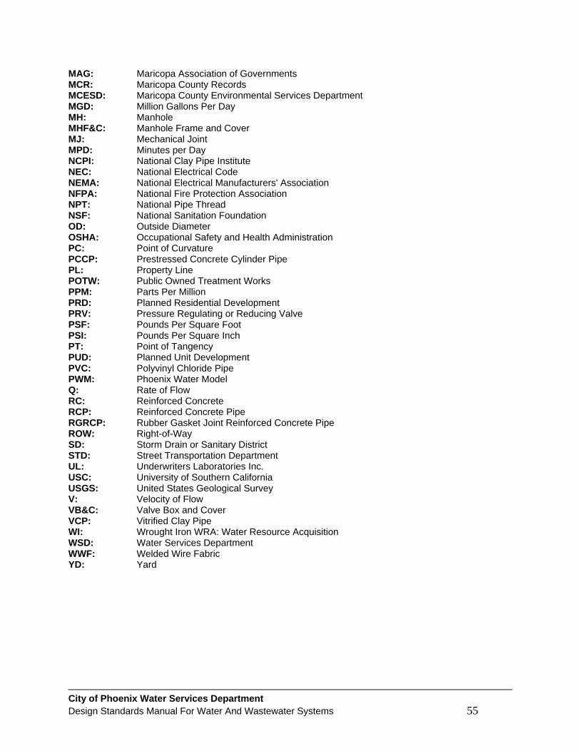
City of Phoenix Water Services Department Design Standards Manual For Water And Wastewater Systems 55
MAG: Maricopa Association of Governments MCR: Maricopa County Records MCESD: Maricopa County Environmental Services Department MGD: Million Gallons Per Day MH: Manhole MHF&C: Manhole Frame and Cover MJ: Mechanical Joint MPD: Minutes per Day NCPI: National Clay Pipe Institute NEC: National Electrical Code NEMA: National Electrical Manufacturers' Association NFPA: National Fire Protection Association NPT: National Pipe Thread NSF: National Sanitation Foundation OD: Outside Diameter OSHA: Occupational Safety and Health Administration PC: Point of Curvature PCCP: Prestressed Concrete Cylinder Pipe PL: Property Line POTW: Public Owned Treatment Works PPM: Parts Per Million PRD: Planned Residential Development PRV: Pressure Regulating or Reducing Valve PSF: Pounds Per Square Foot PSI: Pounds Per Square Inch PT: Point of Tangency PUD: Planned Unit Development PVC: Polyvinyl Chloride Pipe PWM: Phoenix Water Model Q: Rate of Flow RC: Reinforced Concrete RCP: Reinforced Concrete Pipe RGRCP: Rubber Gasket Joint Reinforced Concrete Pipe ROW: Right-of-Way SD: Storm Drain or Sanitary District STD: Street Transportation Department UL: Underwriters Laboratories Inc. USC: University of Southern California USGS: United States Geological Survey V: Velocity of Flow VB&C: Valve Box and Cover VCP: Vitrified Clay Pipe WI: Wrought Iron WRA: Water Resource Acquisition WSD: Water Services Department WWF: Welded Wire Fabric YD: Yard