DESIGN STANDARD DS 71-02 - watercorporation.com.au · Control Functional Specification VERSION 1...
54
Assets Delivery Group Engineering DESIGN STANDARD DS 71-02 Fluorosilicic Acid Storage and Dosing System Control Functional Specification VERSION 1 REVISION 1 OCTOBER 2017
Transcript of DESIGN STANDARD DS 71-02 - watercorporation.com.au · Control Functional Specification VERSION 1...

Assets Delivery Group
Engineering
DESIGN STANDARD DS 71-02
Fluorosilicic Acid Storage and Dosing System
Control Functional Specification
VERSION 1
REVISION 1
OCTOBER 2017

Design Standard DS 71-02
Fluorosilicic Acid Storage and Dosing System
Control Functional Specification
Uncontrolled if Printed Page 2 of 54
Ver 1Rev 1
© Copyright Water Corporation 2008-2017
FOREWORD
The intent of Design Standards is to specify requirements that assure effective design and delivery of fit for
purpose Water Corporation infrastructure assets for best whole-of-life value with least risk to Corporation
service standards and safety. Design standards are also intended to promote uniformity of approach by asset
designers, drafters and constructors to the design, construction, commissioning and delivery of water
infrastructure and to the compatibility of new infrastructure with existing like infrastructure.
Design Standards draw on the asset design, management and field operational experience gained and
documented by the Corporation and by the water industry generally over time. They are intended for
application by Corporation staff, designers, constructors and land developers to the planning, design,
construction and commissioning of Corporation infrastructure including water services provided by land
developers for takeover by the Corporation.
Nothing in this Design Standard diminishes the responsibility of designers and constructors for applying the
requirements of WA OSH Regulations 1996 (Division 12, Construction Industry – consultation on hazards
and safety management) to the delivery of Corporation assets. Information on these statutory requirements
may be viewed at the following web site location:
http://www.commerce.wa.gov.au/WorkSafe/Content/Industries/Construction/Further_information/National_
standard_for_construction.html
Enquiries relating to the technical content of a Design Standard should be directed to the Senior Principal
Engineer, Water (Engineering). Future Design Standard changes, if any, will be issued to registered Design
Standard users as and when published.
Head of Engineering
This document is prepared without the assumption of a duty of care by the Water Corporation. The document is not
intended to be nor should it be relied on as a substitute for professional engineering design expertise or any other
professional advice.
It is the responsibility of the user to ensure they are using the current version of this document.
© Copyright – Water Corporation: This standard and software is copyright. With the exception of use permitted by the
Copyright Act 1968, no part may be reproduced without the written permission of the Water Corporation.

Design Standard DS 71-02
Fluorosilicic Acid Storage and Dosing System
Control Functional Specification
Uncontrolled if Printed Page 3 of 54
Ver 1Rev 1
© Copyright Water Corporation 2008-2017
DISCLAIMER
Water Corporation accepts no liability for any loss or damage that arises from anything in the
Standards/Specifications including any loss or damage that may arise due to the errors and omissions of any
person. Any person or entity which relies upon the Standards/Specifications from the Water Corporation website
does so that their own risk and without any right of recourse to the Water Corporation, including, but not limited
to, using the Standards/Specification for works other than for or on behalf of the Water Corporation.
The Water Corporation shall not be responsible, nor liable, to any person or entity for any loss or damage suffered
as a consequence of the unlawful use of, or reference to, the Standards/Specifications, including but not limited to
the use of any part of the Standards/Specification without first obtaining prior express written permission from the
CEO of the Water Corporation.
Any interpretation of anything in the Standards/Specifications that deviates from specific Water Corporation
Project requirements must be referred to, and resolved by, reference to and for determination by the Water
Corporation’s project manager and/or designer for that particular Project.
Design Standard DS 71-02
Fluorosilicic Acid Storage and Dosing System
Control Functional Specification
Uncontrolled if Printed Page 4 of 54
Ver 1Rev 1
© Copyright Water Corporation 2008-2017
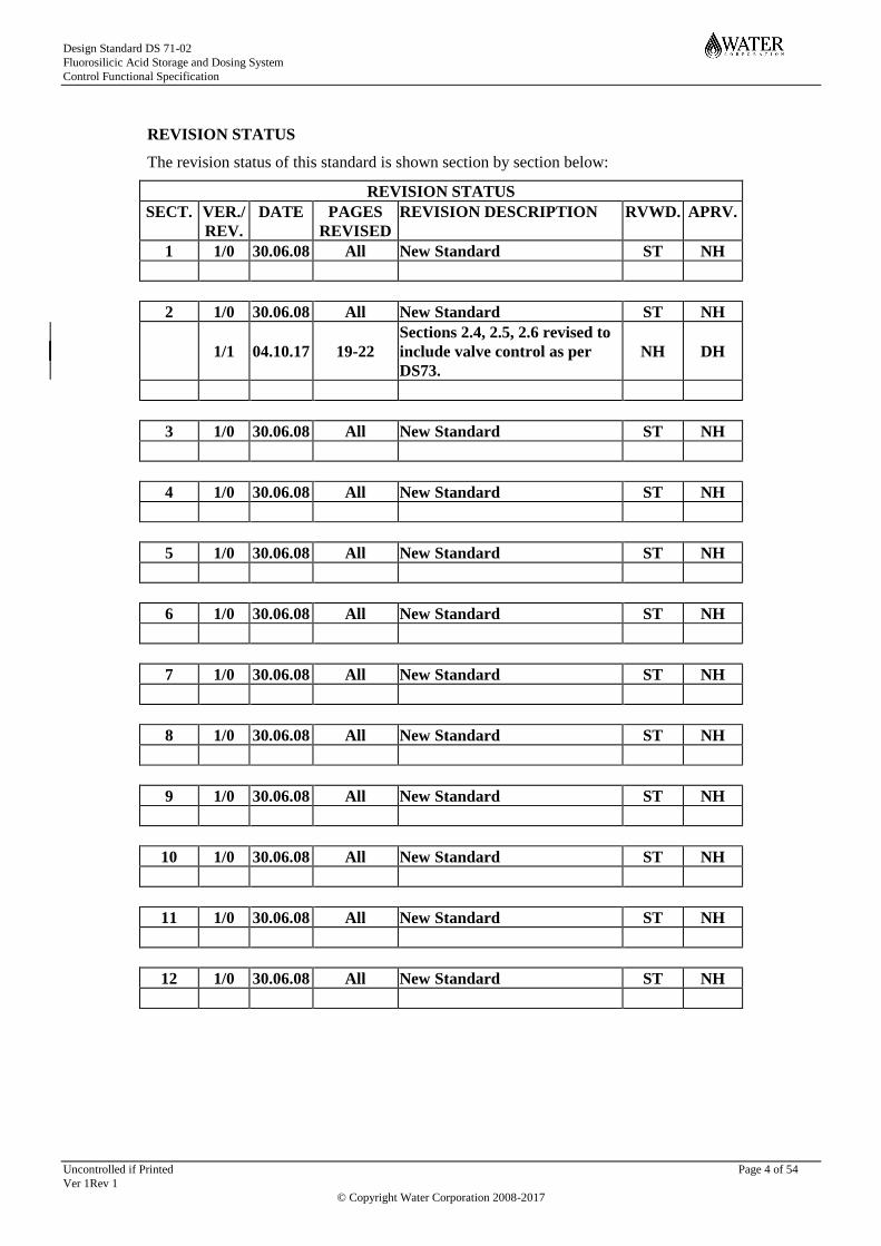
REVISION STATUS
The revision status of this standard is shown section by section below:
REVISION STATUS
SECT. VER./
REV.
DATE PAGES
REVISED
REVISION DESCRIPTION
RVWD. APRV.
1 1/0 30.06.08 All New Standard ST NH
2 1/0 30.06.08 All New Standard ST NH
1/1 04.10.17 19-22
Sections 2.4, 2.5, 2.6 revised to
include valve control as per
DS73.
NH DH
3 1/0 30.06.08 All New Standard ST NH
4 1/0 30.06.08 All New Standard ST NH
5 1/0 30.06.08 All New Standard ST NH
6 1/0 30.06.08 All New Standard ST NH
7 1/0 30.06.08 All New Standard ST NH
8 1/0 30.06.08 All New Standard ST NH
9 1/0 30.06.08 All New Standard ST NH
10 1/0 30.06.08 All New Standard ST NH
11 1/0 30.06.08 All New Standard ST NH
12 1/0 30.06.08 All New Standard ST NH

Design Standard DS 71-02
Fluorosilicic Acid Storage and Dosing System
Control Functional Specification
Uncontrolled if Printed Page 5 of 54
Ver 1Rev 1
© Copyright Water Corporation 2008-2017
DESIGN STANDARD DS 71-02 Fluorosilicic Acid Storage and Dosing System
Control Functional Specification
CONTENTS Section Page
1 SYSTEM OVERVIEW................................................................................................................. 7
1.1 Process Description ...................................................................................................................... 7
1.2 System Functionality ................................................................................................................... 8
1.3 Three Way Valves ...................................................................................................................... 14
1.4 Plant Power Failure ................................................................................................................... 14
2 FSA STORAGE........................................................................................................................... 15
2.1 Set Point and Alarm Configuration ......................................................................................... 15
2.2 Storage Tank No 1 - TA 83110 .................................................................................................. 15
2.3 Storage Tank No 2 - TA 83120 .................................................................................................. 16
2.4 FSA Sump ................................................................................................................................... 17 2.4.1 Conductivity Transmitter AE 83136 ............................................................................................ 17 2.4.2 Drain Valve VA 83137 ................................................................................................................ 17
2.5 Load in Panel .............................................................................................................................. 18
2.6 Load-in Apron Sump ................................................................................................................. 19 2.6.1 Drain Valve VA 83138 ................................................................................................................ 19 2.6.2 Level Switch LSH 83138 ............................................................................................................. 20
2.7 Waste Holding Tank .................................................................................................................. 20
3 FSA DOSING SYSTEM ............................................................................................................. 21
3.1 FSA Dosing System Equipment ................................................................................................ 21 3.1.1 FSA System 1............................................................................................................................... 21 3.1.2 FSA System 2............................................................................................................................... 23
4 FSA SAMPLING, ANALYSING & MISCELLANEOUS SYSTEMS ................................... 26
4.1 FSA Sampling & Analysing System Equipment ..................................................................... 26
4.2 Miscellaneous Equipment – Safety Showers, Hose Reels & Exhaust Systems .................... 27
5 CONTROL LOOPS AND CALCULATIONS ......................................................................... 28
Design Standard DS 71-02
Fluorosilicic Acid Storage and Dosing System
Control Functional Specification
Uncontrolled if Printed Page 6 of 54
Ver 1Rev 1
© Copyright Water Corporation 2008-2017
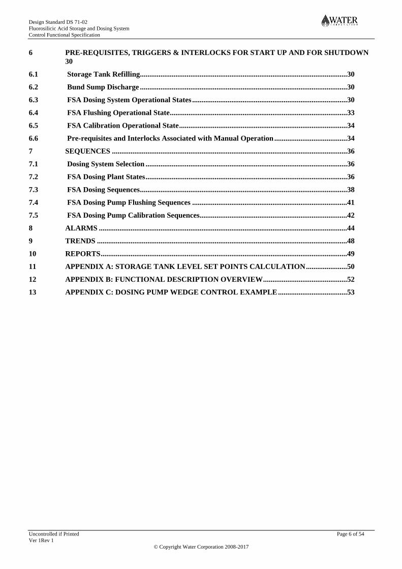
6 PRE-REQUISITES, TRIGGERS & INTERLOCKS FOR START UP AND FOR SHUTDOWN
30
6.1 Storage Tank Refilling............................................................................................................... 30
6.2 Bund Sump Discharge ............................................................................................................... 30
6.3 FSA Dosing System Operational States ................................................................................... 30
6.4 FSA Flushing Operational State ............................................................................................... 33
6.5 FSA Calibration Operational State .......................................................................................... 34
6.6 Pre-requisites and Interlocks Associated with Manual Operation ....................................... 34
7 SEQUENCES .............................................................................................................................. 36
7.1 Dosing System Selection ............................................................................................................ 36
7.2 FSA Dosing Plant States ............................................................................................................ 36
7.3 FSA Dosing Sequences ............................................................................................................... 38
7.4 FSA Dosing Pump Flushing Sequences ................................................................................... 41
7.5 FSA Dosing Pump Calibration Sequences............................................................................... 42
8 ALARMS ..................................................................................................................................... 44
9 TRENDS ...................................................................................................................................... 48
10 REPORTS .................................................................................................................................... 49
11 APPENDIX A: STORAGE TANK LEVEL SET POINTS CALCULATION ...................... 50
12 APPENDIX B: FUNCTIONAL DESCRIPTION OVERVIEW ............................................. 52
13 APPENDIX C: DOSING PUMP WEDGE CONTROL EXAMPLE ..................................... 53

Design Standard DS 71-02
Fluorosilicic Acid Storage and Dosing System
Control Functional Specification
Uncontrolled if Printed Page 7 of 54
Ver 1Rev 1
© Copyright Water Corporation 2008-2017
1 SYSTEM OVERVIEW
The Fluorosilicic Acid (FSA) system normally operates automatically but may also be operated
manually from the local fluoride control panel (Fluoride Local Interface Panel or FLIP) located in the
entry vestibule or viewing room of the FSA plant. Manual operation of the FSA system from the
plant-wide supervisory control system (HMI) is not recommended as onsite observation would be
required to minimize potential safety hazards. Most current FSA installations do permit remote
manual operation but it is intended that changes will be made to restrict remote operation other than
dose rate changes in future. Information provided on the HMI for the FSA system is also duplicated
and displayed on the FLIP.
The 2 Tanks & 2 Panels standard FSA design consists of two complete and separate dosing systems
that operate as duty and standby. Each system comprises of a tank and dosing panel including
actuated valves, pump and flow meter. Should a device in the duty dosing system fail, prompting a
changeover to the standby system, then the complete standby system will commence operation taking
the place of the entire failed system, not just part of the standby system.
This control functional specification is written specifically for 2 Tanks & 2 Panels standard design
systems. Refer to P&IDs GT36-60-83.1 through to 83.4 for valve and equipment numbers. Sections
of the text have been highlighted in green to indicate the differences between systems using chlorine
solution water as the FSA dilution water and systems using service water, or some other supply, as the
FSA dilution water.
1.1 Process Description
The FSA is stored in two <volume> m3 <material> tanks inside a bund within a sealed room. The
volume inside each tank is monitored by a pressure transmitter. A magnetic level indicator is also
installed on each tank to provide local visual indication of the tank level and to assist in checking the
calibration of the pressure transmitters.
Fluorosilicic acid solution is loaded into the tanks through a load-in panel. Displays on the front of
the load-in panel show the volume in each tank, level alarm lights and sirens.
The bund sump is equipped with a conductivity probe and high level switch to assist in the detection
of acid leaks. The bund sump is connected to the load-in apron sump via an actuated isolation valve
(located in an external pit). The load-in apron sump drains to the sludge drying beds or site drainage
via a manual isolation valve. This valve is normally open to prevent rain water accumulating on the
apron and in the sump. It is closed during a delivery to capture minor spills.
Each tank has a manual isolation valve, actuated isolation valve and a three-way actuated acid/water
selector valve connected as close as possible to the process outlet. A flushing water line and actuated
valve is also located in close proximity. The piping arrangement aims to maximise the effectiveness
and efficiency of the automated pipework flushing system. Each tank is plumbed to a dedicated
dosing panel which holds a calibration column, strainer, dosing pump, pulsation dampener, acid flow
meter, dilution water and acid dosing pipework, along with other valves and equipment. These panels
are mounted on the storage room walls and have transparent PVC screens or doors for additional
protection from leaks and sprays.
Dosing systems for chemicals other than FSA often employ duty and standby equipment within a
single dosing system to provide a high degree of continuity of dosing. However, it is desirable to
minimise complexity in FSA dosing system designs so as to reduce the potential for leakage and the
associated OSH hazards. In an effort to achieve a degree of simplicity, separate duty and standby
dosing systems are provided with no cross-connections. This provides two main benefits:
it minimises the number of connections, and thus the potential number of points that may leak;
and

Design Standard DS 71-02
Fluorosilicic Acid Storage and Dosing System
Control Functional Specification
Uncontrolled if Printed Page 8 of 54
Ver 1Rev 1
© Copyright Water Corporation 2008-2017
it allows maintenance to be safely done on one dosing system, while the other dosing system is
in operation, safely sealed in a separate dosing cabinet.
<If FSA and chlorine are dosed together ie chlorine solution is used as the dilution water>
FSA is conveyed to the dose point in solution water (dilution water with a minimum twenty-fold
dilution at the maximum dose rate). FSA is added to the chlorine solution water (i.e. downstream of
the addition of chlorine to the solution water) and thus chlorine and FSA are dosed together. The
controlled addition of fluoride ions into the drinking water achieves a pre-set fluoride concentration in
the drinking water.
<If FSA is dosed separate from chlorine ie service water or dedicated pumps provide dilution water>
FSA is conveyed to the dose point in service water (dilution water with a minimum twenty-fold
dilution at the maximum dose rate). The controlled addition of fluoride ions into the drinking water
achieves a preset fluoride concentration in the drinking water.
The FSA dose rate is flow-paced from a magflow meter installed in the recipient water main. A mini-
magflow meter on the neat acid line on the dosing panel provides a signal used for feedback control of
the dose pump speed to achieve the target dose rate.
An online fluoride ion analyser is used to monitor the fluoride ion concentration in the recipient water
main. A continuous water sample is drawn from downstream of the dose point to supply this
analyser. The signal from this analyser is not normally used to control the fluoride dose rate (no
feedback trim from this analyser) but alarms generated from this analyser are used to alert the
operator to high or low fluoride concentrations in the water supply and shutdown fluoride dosing on
high-high concentration. However, at sites where the background fluoride concentration of the raw
water or recipient water varies widely, feedback trim from the analyser could be considered.
Exhaust fans are located inside the storage room. Safety showers are located both inside and outside
the FSA storage room. These are equipped with flow switches to indicate continuous operation and
the external safety shower is equipped with a thermostatic bleed valve.
1.2 System Functionality
Fluoride dosing occurs when:
the flow rate in the recipient water main exceeds a set point minimum value; and
when dilution water is running through the duty dosing panel.
<For systems where chlorine solution is used as the dilution water>
Dilution water is registered as running when the low flow switches1 are not active in the lines
carrying chlorinated water to the fluoride dosing system (i.e. when ‘dose water flow
established’ signal is registered - refer to chlorine standard drawing EO28-60-8)
<For systems where service water or a dilution pump is used to supply the dilution water>
Dilution water is registered as running when the low flow switches on the dosing panels (FSL
83205 for panel 1 and FSL 83305 for panel 2) are not active.
The FSA storage and dosing systems incorporate a number of different operations and these are
summarised in the following table:
1 Ordinarily, chlorination would only be operating when the minimum flow rate in the recipient water main had been achieved, but it is possible that the flow
switches may also be active during system testing or flushing; hence, the FSA system requires both the establishment of the minimum flow rate and the
chlorine solution water flow switches being active.
Design Standard DS 71-02
Fluorosilicic Acid Storage and Dosing System
Control Functional Specification
Uncontrolled if Printed Page 9 of 54
Ver 1Rev 1
© Copyright Water Corporation 2008-2017
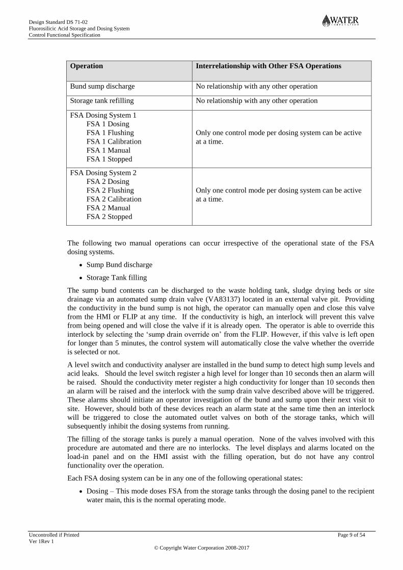
Operation Interrelationship with Other FSA Operations
Bund sump discharge No relationship with any other operation
Storage tank refilling No relationship with any other operation
FSA Dosing System 1
FSA 1 Dosing
FSA 1 Flushing
FSA 1 Calibration
FSA 1 Manual
FSA 1 Stopped
Only one control mode per dosing system can be active
at a time.
FSA Dosing System 2
FSA 2 Dosing
FSA 2 Flushing
FSA 2 Calibration
FSA 2 Manual
FSA 2 Stopped
Only one control mode per dosing system can be active
at a time.
The following two manual operations can occur irrespective of the operational state of the FSA
dosing systems.
Sump Bund discharge
Storage Tank filling
The sump bund contents can be discharged to the waste holding tank, sludge drying beds or site
drainage via an automated sump drain valve (VA83137) located in an external valve pit. Providing
the conductivity in the bund sump is not high, the operator can manually open and close this valve
from the HMI or FLIP at any time. If the conductivity is high, an interlock will prevent this valve
from being opened and will close the valve if it is already open. The operator is able to override this
interlock by selecting the ‘sump drain override on’ from the FLIP. However, if this valve is left open
for longer than 5 minutes, the control system will automatically close the valve whether the override
is selected or not.
A level switch and conductivity analyser are installed in the bund sump to detect high sump levels and
acid leaks. Should the level switch register a high level for longer than 10 seconds then an alarm will
be raised. Should the conductivity meter register a high conductivity for longer than 10 seconds then
an alarm will be raised and the interlock with the sump drain valve described above will be triggered.
These alarms should initiate an operator investigation of the bund and sump upon their next visit to
site. However, should both of these devices reach an alarm state at the same time then an interlock
will be triggered to close the automated outlet valves on both of the storage tanks, which will
subsequently inhibit the dosing systems from running.
The filling of the storage tanks is purely a manual operation. None of the valves involved with this
procedure are automated and there are no interlocks. The level displays and alarms located on the
load-in panel and on the HMI assist with the filling operation, but do not have any control
functionality over the operation.
Each FSA dosing system can be in any one of the following operational states:
Dosing – This mode doses FSA from the storage tanks through the dosing panel to the recipient
water main, this is the normal operating mode.

Design Standard DS 71-02
Fluorosilicic Acid Storage and Dosing System
Control Functional Specification
Uncontrolled if Printed Page 10 of 54
Ver 1Rev 1
© Copyright Water Corporation 2008-2017
Flushing – This mode uses flushing water to displace FSA out of the system and directs it to the
dose point, so that maintenance can be conducted on the system.
Calibration – This mode is used to calibrate the dosing pump using service water from the
calibration column and directs it to the dose point, this mode will be used predominantly during
commissioning or after pump replacement.
Manual – This mode allows the operator to open/close and stop/start any component of the FSA
system. This is not a normal operating mode.
Stopped – This mode stops the dosing, flushing or calibration systems and isolates the tanks.
This mode is a safe state and is also used as a starting point for the selection of other modes.
Only one mode can be selected to be active at a time and this selection will only be permitted when
there is no other control mode selected. This means the Operator can only select a mode when the
system is in the ‘FSA <dosing system number> Stopped’ state.
Operators can manually de-activate a mode to return the system to the ‘FSA <dosing system number>
Stopped’ state. Or the control system may abort a mode due to an interlock or trigger and return the
system to a stopped state.
When a control mode is selected by the operator for dosing system 1 the corresponding actuated valve
configuration and pump control selection is undertaken automatically:
FSA 1 Dosing –
The actuated tank isolation valve (VA83117) will be opened.
The acid/water valve (VA83118) will be opened to the acid position.
The flushing isolation valve (VA83132) will be closed.
The dilution water valve (VA83202) will be opened.
The dose/drain valve (VA83224) will be opened to the dose position.
The dosing pump (PU83213) speed is set to automatic control. The manual control of
the pump (speed control) is not permitted in dosing mode.
FSA 1 Flushing –
The actuated tank isolation valve (VA83117) will be closed.
The acid/water valve (VA83118) will be closed (open in the water position).
The flushing isolation valve (VA83132) will be opened.
The dilution water valve (VA83202) will be opened.
The dose/drain valve (VA83224) will initially be opened to the dose position. After
initial valve configuration, the dose/drain valve can be manually opened or closed to
dose or drain.
The dosing pump (PU83213) speed is set to automatic control; manual control of the
pump (speed control) is not permitted.
FSA 1 Calibration –
The actuated tank isolation valve (VA83117) will be closed.
The acid/water valve (VA83118) will be closed (in the water position).
The flushing isolation valve (VA83132) will be closed.
The dilution water valve (VA83202) will be opened.
The dose/drain valve (VA83224) will be opened in the dose position.

Design Standard DS 71-02
Fluorosilicic Acid Storage and Dosing System
Control Functional Specification
Uncontrolled if Printed Page 11 of 54
Ver 1Rev 1
© Copyright Water Corporation 2008-2017
The dosing pump (PU83213) speed is under manual control and the pump speed can
be selected.
The operator will normally close the manual supply valve (VA83209) and open the
calibration tube downstream valve (VA83208) after filling the calibration tube from
the site service water via valve (VA83206).
FSA 1 Manual –
All valves can be positioned as required with the exception of one interlock (if the
acid/water valve (VA83118) is open (in the acid position) then the dose/drain valve
(VA83224) must be open (in the dose position). The dose drain valve cannot be
opened to drain whilst the acid/water valve is open to acid).
The pump is under manual control and the pump speed can be manually set.
FSA 1 Stopped –
The actuated tank isolation valve (VA83117) will be closed.
The acid/water valve (VA83118) will hold its last position.
The flushing isolation valve (VA83132) will be closed.
The dilution water valve (VA83202) will be closed.
The dose/drain valve (VA83224) will hold its last position.
The dosing pump (PU83213) speed control is set to off.
The same control modes exist for dosing system 2 – FSA 2 Dosing, FSA 2 Flushing, FSA 2
Calibration, FSA 2 Manual and FSA 2 Stopped. Similar automatic valve actuation occurs when each
of these modes is initiated by the operator.
Each FSA dosing system is moved between each of these operational states by executing sequences
initiated from the commands on the pop-up panel on the HMI/FLIP display, or by tripped interlocks
and triggers. The commands available on the HMI/FLIP Sequence Controls pop-up panel for each
system are:
Dosing Mode Start
Dosing Mode Stop
Flushing Mode Start
Flushing Mode Stop
Calibration Mode Start
Calibration Mode Stop
Manual Mode Start
Manual Mode Stop
The FSA <dosing system number> Dosing Pump can only commence running automatically when the
system is in the ‘FSA <dosing system number> Dosing Mode’ operational state. Transition to the
‘FSA <dosing system number> Dosing Mode’ state can only occur from the ‘FSA <dosing system
number> Stopped’ state by an Operator selecting ‘FSA <dosing system number> Dosing Mode Start’
command.
Once in the ‘FSA <dosing system number> Dosing Mode’ the FSA <dosing system number> Dosing
Pump is automatically initiated by the control system when the minimum set point flow rate in the
recipient water main is exceeded for at least 30 seconds. When this condition ceases (when recipient
water flow drops below the minimum set point for at least 30 seconds) then the FSA dosing pump will
automatically stop operating and the system will sit idle in the ‘FSA <system> Dosing Mode’ state.

Design Standard DS 71-02
Fluorosilicic Acid Storage and Dosing System
Control Functional Specification
Uncontrolled if Printed Page 12 of 54
Ver 1Rev 1
© Copyright Water Corporation 2008-2017
The FSA dosing system can transition to the ‘FSA Stopped’ state by the Operator selecting any of the
following commands from the Sequence Controls pop up panel,
FSA <dosing system number> Dosing Mode Stop
FSA <dosing system number> Flushing Mode Stop
FSA <dosing system number> Calibration Mode Stop
FSA <dosing system number> Manual Mode Stop
In the ‘FSA Stopped’ state, the dosing system cannot transition automatically to the ‘FSA Dosing
Mode’ state and hence the dosing pump cannot run.
Transition to the ‘FSA <system number> Flushing Mode’ state can only occur from the ‘FSA
Stopped’ state. This is achieved by the Operator selecting the ‘FSA <system number> Flushing Mode
Start’ command. Once selected, the flushing operation will continue to run until the operator
command ‘FSA <dosing system number>Flushing Mode Stop’ is activated or an interlock terminates
the flushing operation and returns the system to the ‘FSA <dosing system number> Stopped’ state.
Transition to the ‘FSA <dosing system number> Calibration Mode’ state can only occur from the
‘FSA Stopped’ state. This is achieved by the Operator selecting the ‘FSA <dosing system number>
Calibration Mode Start’ command. The ‘FSA <dosing system number> Calibration Mode Stop’
command will terminate the calibration operation and return the system to the ‘FSA <dosing system
number> Stopped’ state.
The transition between the operating states is shown diagrammatically in Section 7.2. The pre-
requisites for the ‘FSA <dosing system number> Dosing’, ‘FSA <dosing system number> Flushing’
and ‘FSA <dosing system number> Calibration’ control sequence and the interlocks associated with
these sequences are described in detail in Sections 6.3, 6.4 and 6.5 respectively.
To facilitate the above control sequences, the PLC controlled valves, instruments and dosing pumps
associated with each FSA dosing system are grouped together within the control system under a
Group Controller identified as ‘FSA <dosing system number>_GC’. The purpose of the group
controller is to,
1. Monitor the ‘Available’ (health) status of each of the devices that will be controlled by the
sequences,
2. Allow the operator to place all the affected FSA dosing system controllable field devices into
an ‘Automatic state’, thereby ensuring that the control sequences that will actuate these devices
will succeed.
The control sequences that rely on the response of these devices is prevented or stopped from
executing if the group controller does not have the required list of ‘Available’ devices.
Group Controller FSA <dosing system number>_GC has two states that can be selected on the HMI
and FLIP screen,
AUTO This state prohibits the Operator from initiating pump or individual valve operation from
the HMI and FLIP screen.
MANUAL Control sequences cannot be initiated therefore only ‘Manual Mode’ can be selected.
The Operator has control access to the individual items of equipment controllable from
the FLIP or HMI display. Manual control is recommended to be carried out from the
FLIP where the operator has full view of the FSA room.
Design Standard DS 71-02
Fluorosilicic Acid Storage and Dosing System
Control Functional Specification
Uncontrolled if Printed Page 13 of 54
Ver 1Rev 1
© Copyright Water Corporation 2008-2017
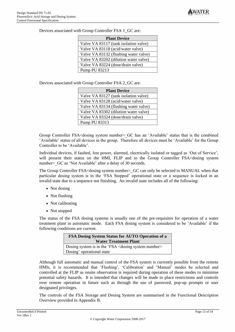
Devices associated with Group Controller FSA 1_GC are:
Plant Device
Valve VA 83117 (tank isolation valve)
Valve VA 83118 (acid/water valve)
Valve VA 83132 (flushing water valve)
Valve VA 83202 (dilution water valve)
Valve VA 83224 (dose/drain valve)
Pump PU 83213
Devices associated with Group Controller FSA 2_GC are:
Plant Device
Valve VA 83127 (tank isolation valve)
Valve VA 83128 (acid/water valve)
Valve VA 83134 (flushing water valve)
Valve VA 83302 (dilution water valve)
Valve VA 83324 (dose/drain valve)
Pump PU 83313
Group Controller FSA<dosing system number>_GC has an ‘Available’ status that is the combined
‘Available’ status of all devices in the group. Therefore all devices must be ‘Available’ for the Group
Controller to be ‘Available’.
Individual devices, if faulted, lost power, alarmed, electrically isolated or tagged as ‘Out of Service’,
will present their status on the HMI, FLIP and to the Group Controller FSA<dosing system
number>_GC as ‘Not Available’ after a delay of 30 seconds.
The Group Controller FSA<dosing system number>_GC can only be selected to MANUAL when that
particular dosing system is in the ‘FSA Stopped’ operational state or a sequence is locked in an
invalid state due to a sequence not finishing. An invalid state includes all of the following:
Not dosing
Not flushing
Not calibrating
Not stopped
The status of the FSA dosing systems is usually one of the pre-requisites for operation of a water
treatment plant in automatic mode. Each FSA dosing system is considered to be ‘Available’ if the
following conditions are current.
FSA Dosing System Status for AUTO Operation of a
Water Treatment Plant
Dosing system is in the ‘FSA <dosing system number>
Dosing’ operational state
Although full automatic and manual control of the FSA system is currently possible from the remote
HMIs, it is recommended that ‘Flushing’, ‘Calibration’ and ‘Manual’ modes be selected and
controlled at the FLIP as onsite observation is required during operation of these modes to minimise
potential safety hazards. It is intended that changes will be made to place restrictions and controls
over remote operation in future such as through the use of password, pop-up prompts or user
designated privileges.
The controls of the FSA Storage and Dosing System are summarised in the Functional Description
Overview provided in Appendix B.

Design Standard DS 71-02
Fluorosilicic Acid Storage and Dosing System
Control Functional Specification
Uncontrolled if Printed Page 14 of 54
Ver 1Rev 1
© Copyright Water Corporation 2008-2017
1.3 Three Way Valves
The convention for labelling the status of the three way valves will be as follows:
1. Open state –
acid/water valve configured to allow acid from the tank to flow to the dosing panel; and
dose/drain valve configured to allow acid flow into the dilution water line which is dosed into
the recipient water main.
2. Closed state –
acid/water valve configured to allow flushing water to flow to the dosing panel; and
dose/drain valve configured to allow flushing water to flow to the tundish on the dosing panel.
1.4 Plant Power Failure
A UPS provides continuous power to the Control system and the Fluoridation Control Cubicle for a
minimum period of 30 minutes in the event when no input power supply is available. In addition to
this the fluoride analyser is connected to this supply so fluoride levels can continue to be monitored
and alarmed. Containment, security alarms and process alarms generated in the PLC will continue to
be active during this time.
In the event of a plant power failure during FSA dosing, the system shall resume dosing automatically
following restoration of power (either from mains or generator) and return of the permissive
conditions such as the minimum set point flow rate in the water main. The low fluoride level in the
treated water or other fault/alarm directly due to the plant power failure should not trigger a shutdown
or system changeover when the power is restored i.e. a time delay shall be allowed for the fluoride
residual to return to normal. However, if the system is in ‘Manual’ mode, it shall revert to the
‘Stopped’ (off) mode in the event of a power failure, and thus the equipment shall remain off when
power is restored.
At sites where backup generator is available, automatic start-up of the generator backup power supply
(typically 5 seconds after loss of power) will allow chemical dosing to continue with all loads
supported except for miscellaneous non-essential loads. The fuel tank of the generator backup power
supply is sized to provide continuous running on normal load for 3 days.

Design Standard DS 71-02
Fluorosilicic Acid Storage and Dosing System
Control Functional Specification
Uncontrolled if Printed Page 15 of 54
Ver 1Rev 1
© Copyright Water Corporation 2008-2017
2 FSA STORAGE
2.1 Set Point and Alarm Configuration
The set point and alarm values listed in the following sections are all configured on the HMI and FLIP
screens. The values can only be changed by personnel with supervisory log-on privileges.
2.2 Storage Tank No 1 - TA 83110
The storage tank incorporates the following instrumentation and automated valve.
The level/volume in this tank is measured by a pressure transmitter LT83113, calibrated to 0 – 100%
with the following PLC set points. (0% is defined as the bottom of the tank, and 100% is defined as
the invert level of the tank overflow)
Tag Number Set Point Functionality
LAH83113 80% LAH 83113 is a local visual alarm to notify the delivery tanker
operator to stop filling. An alarm condition is also displayed on the
HMI and FLIP screens.
LAL 83113 40% LAL 83113 is a low level alarm displayed on the HMI and FLIP
screens to indicate the need to order more chemical.
LALL 83113 7% LALL 83112 is a low level alarm displayed on the HMI and FLIP
screens to indicate that the tank is nearing empty.
This alarm will inhibit the selection of dosing mode for FSA system
1 and will shutdown dosing if it is already occurring when the this
alarm is generated to prevent the dosing pump from running dry.
Note: The set point values listed above are provided as a guide only. They will need to be determined
for each site based on tank volume, delivery volume and delivery turn around. Some notes on the
determination of these set points are provided in appendix A.
A magnetic bar graph level indicator LI 83110 complete with a level switch LSHH 83110 is also
installed on tank TA 83110 to provide visual indication of the tank level and to trigger the high-high
level alarm.
Tag Number Set Point Functionality
LI 83110 Not applicable LI 83110 is a visual indication of tank level only.
LSHH83110 85% LAHH 83110 is a local visual and audible alarm on load-in panel to
alert that the tank is close to overflowing. An alarm condition is
also displayed on the HMI and FLIP screens.
Tank TA 83110 discharge valve VA 83117 is a motorised valve with limit switches to indicate valve
position on the HMI and FLIP displays. Refer to the dosing section for the description of control for
this valve.

Design Standard DS 71-02
Fluorosilicic Acid Storage and Dosing System
Control Functional Specification
Uncontrolled if Printed Page 16 of 54
Ver 1Rev 1
© Copyright Water Corporation 2008-2017
Tag Number Set Point Functionality
ZSH 83117 Fully open Indication to notify the control system that valve VA 83117 is open.
This forms part an interlock to enable the dosing system to operate.
ZSL 83117 Fully closed Indication to notify the control system that valve VA 83117 is
closed.
This forms part of an interlock to enable the flushing and calibration
modes to operate.
ZA 83117 Valve fault If VA 83117 fails an alarm is registered.
This forms part of a pre-requisite and interlock to enable operating
modes to be selected.
2.3 Storage Tank No 2 - TA 83120
The storage tank incorporates the following instrumentation and automated valve.
The level/volume in this tank is measured by a pressure transmitter LT83123, calibrated to 0 – 100%
with the following PLC set points. (0% is defined as the bottom of the tank, and 100% is defined as
the invert level of the tank overflow)
Tag Number Set Point Functionality
LAH 83123 80% LAH 83123 is a local visual alarm to notify the delivery tanker
operator to stop filling. An alarm condition is also displayed on the
HMI and FLIP screens.
LAL 83123 40% LAL 83123 is a low-low level alarm displayed on the HMI and
FLIP screens to indicate the need to order more chemical.
LALL 83123 7% LALL 83123 is a low-low level alarm displayed on the HMI and
FLIP screens.
This alarm will inhibit the selection of dosing mode for FSA system
1 and will shutdown dosing if it is already occurring when the this
alarm is generated to prevent the dosing pump from running dry.
A magnetic bar graph level indicator LI 83120 complete with a level switch LSHH 83120 is also
installed on tank TA 83120 to provide visual indication of the tank level.
Tag Number Set Point Functionality
LI83120 Not applicable LI83120 is a visual indication of tank level only.
LSHH 83120 85% LAHH 83120 is a local visual and audible alarm on the load-in
panel to alert that the tank is close to overflowing. An alarm
condition is also displayed on the HMI and FLIP screens.
Tank TA 83120 discharge valve VA 83127 is a motorised valve with limit switches to indicate valve
position on the HMI and FLIP displays. Refer to the dosing section for the description of control for
this valve.
Design Standard DS 71-02
Fluorosilicic Acid Storage and Dosing System
Control Functional Specification
Uncontrolled if Printed Page 17 of 54
Ver 1Rev 1
© Copyright Water Corporation 2008-2017
Tag Number Set Point Functionality
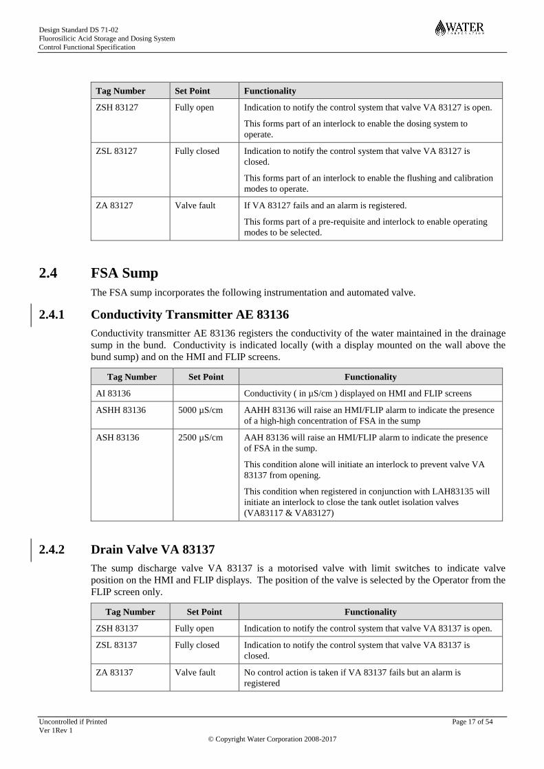
ZSH 83127 Fully open Indication to notify the control system that valve VA 83127 is open.
This forms part of an interlock to enable the dosing system to
operate.
ZSL 83127 Fully closed Indication to notify the control system that valve VA 83127 is
closed.
This forms part of an interlock to enable the flushing and calibration
modes to operate.
ZA 83127 Valve fault If VA 83127 fails and an alarm is registered.
This forms part of a pre-requisite and interlock to enable operating
modes to be selected.
2.4 FSA Sump
The FSA sump incorporates the following instrumentation and automated valve.
2.4.1 Conductivity Transmitter AE 83136
Conductivity transmitter AE 83136 registers the conductivity of the water maintained in the drainage
sump in the bund. Conductivity is indicated locally (with a display mounted on the wall above the
bund sump) and on the HMI and FLIP screens.
Tag Number Set Point Functionality
AI 83136 Conductivity ( in µS/cm ) displayed on HMI and FLIP screens
ASHH 83136 5000 µS/cm AAHH 83136 will raise an HMI/FLIP alarm to indicate the presence
of a high-high concentration of FSA in the sump
ASH 83136 2500 µS/cm AAH 83136 will raise an HMI/FLIP alarm to indicate the presence
of FSA in the sump.
This condition alone will initiate an interlock to prevent valve VA
83137 from opening.
This condition when registered in conjunction with LAH83135 will
initiate an interlock to close the tank outlet isolation valves
(VA83117 & VA83127)
2.4.2 Drain Valve VA 83137
The sump discharge valve VA 83137 is a motorised valve with limit switches to indicate valve
position on the HMI and FLIP displays. The position of the valve is selected by the Operator from the
FLIP screen only.
Tag Number Set Point Functionality
ZSH 83137 Fully open Indication to notify the control system that valve VA 83137 is open.
ZSL 83137 Fully closed Indication to notify the control system that valve VA 83137 is
closed.
ZA 83137 Valve fault No control action is taken if VA 83137 fails but an alarm is
registered

Design Standard DS 71-02
Fluorosilicic Acid Storage and Dosing System
Control Functional Specification
Uncontrolled if Printed Page 18 of 54
Ver 1Rev 1
© Copyright Water Corporation 2008-2017
Level switch LSH 83135 is installed in the sump to register an alarm high level condition.
Tag Number Set Point Functionality
LSH 83135 Not applicable LAH 83135 is a high level alarm to indicate a high level in the sump.
No control action is taken when this alarm occurs individually, but if
ASH83136 is raised at the same time an interlock to close both the
tank outlet isolation valves is initiated.
The operator can override these interlocks by selecting the sump drain valve ‘Override On’ locally
from the FLIP. However if the valve is left open for longer than 5 minutes continuously then the
control system will automatically close the valve whether override is selected or not.
Tag Number Set Point Functionality
HS 83137B Override selector on/off switch at OIP
HS 83137A Switch to open or close valve manually at OIP.
ZSH 83137 Fully open ZIH 83137 notifies the control system that valve VA 83137 is open.
• If valve open for longer than 5 mins continuously, control
system automatically closes valve whether override is selected or not.
ZIM 83137 Indicates that the valve is in transition.
ZSL 83137 Fully closed ZIL 83137 notifies the control system that valve VA 83137 is closed.
ZA 83137 Valve fault If VA 83137 fails to reach an open or closed state within a set time, a
fault alarm is registered, no control action.
2.5 Load in Panel
The load in panel displays the level of FSA in the storage tanks and provides relevant information
regarding the chemical bund to the chemical delivery operator. Its main purpose is to inform the
delivery vehicle operator of a potential overflow condition and opening status indication of the apron
sump’s 3-way drainage valve. The following alarm lights and sirens are located on the panel. The
alarm status of the parent instrument is also shown in the table below.
Parent Instrument Instrument alarm status Load in panel indication
LT 83113 LI 83113 Displays volume in tank TA 83110
LAH 83113 ‘FSA Tank 1 High Level’ light illuminated
LSHH 83110 LAHH 83110 ‘FSA Tank 1 High-high Level’ light
illuminated and siren sounds
LT 83123 LI 83123 Displays volume in tank TA 83120
LAH 83123 ‘FSA Tank 2 High Level’ light illuminated
LSHH 83120 LAHH 83120 ‘FSA Tank 2 High-high Level’ light
illuminated and siren sounds
ZSH 83138 ZIH 83138 “Open to Drainage” light illuminated
ZSL 83138 ZIL 83138 “Open to Waste Tank” light illuminated

Design Standard DS 71-02
Fluorosilicic Acid Storage and Dosing System
Control Functional Specification
Uncontrolled if Printed Page 19 of 54
Ver 1Rev 1
© Copyright Water Corporation 2008-2017
The sirens can be silenced by a local hand switches (HS83113/HS83123), these hand switches do not
interface with the control system, they only mute the audible alarms. The alarms will not reset until
the alarm conditions are removed.
For maintenance purposes the operation of these sirens and alarms can be tested by a local hand
switch (HS83150).
2.6 Load-in Apron Sump
The load-in apron sump incorporates the following instrumentation and automated valve.
2.6.1 Drain Valve VA 83138
Under normal conditions, the load-in apron sump drains to the soakwell (or site stormwater drainage)
through a motorised 3-way valve (VA 83138), preventing rainwater accumulating on the load-in
apron. When a delivery load-in transfer to the storage tanks is to take place, the apron sump will have
to be isolated from the soakwell/site drainage and open to the waste holding tank in anticipation of
any potential chemical spillage.
At sites where the security system is not linked to the load-in system, this change in the 3-way valve
opening position is triggered automatically by de-activation of a switch (YS 83106) when the door to
the load-in panel is opened. At the end of the load-in process, the door to the load-in panel would be
closed activating the switch to revert the valve back to its normal state of ‘open to site drainage’ and
‘closed to the waste holding tank’.
In the event of the switch failure or power outage, the apron sump drain valve shall automatically
position to “open to the waste holding tank” (and closed to the site drainage).
The displays and alarms located on the load-in panel and on the HMI assist with the filling operation,
but do not have any control functionality over the operation. Manual override operation of the apron
sump 3-way valve is also possible with a two position switch to select the valve to “open to waste
holding tank” or to “open to site drainage”.
The apron sump 3-way valve VA 83138 has limit switches to indicate valve position on the HMI and
OIP displays.
Tag Number Set Point Functionality
YS 83106 Switch activated by closing of the load-in door
• VA 83138 opens to site drainage (close to waste holding tank).
Switch de-activated by the opening of the load-in door. HMI
indication YI 83106 on HMI & FLIP screens “Load-in door open”
• VA 83138 opens to waste holding tank (and close to drainage).
HS 83138A Override selector Auto/Manual switch at OIP
HS 83138B Switch to open (to site drainage) or close (to waste holding tank)
valve manually at OIP.
ZIH 83138 Fully open ZIH 83138 notifies the control system that valve VA 83138 is open
to drainage (closed to waste holding tank) including a light indication
on the load-in panel.
ZIL 83138 Fully closed ZIL 83138 notifies the control system that valve VA 83138 is open
to waste holding tank (closed to drainage) including a light indication
on the load-in panel.
ZA 83138 Valve fault If VA 83138 fails an alarm is registered.
• VA 83138 to be requested to open to waste holding tank (and
closed to drainage) on valve fault.

Design Standard DS 71-02
Fluorosilicic Acid Storage and Dosing System
Control Functional Specification
Uncontrolled if Printed Page 20 of 54
Ver 1Rev 1
© Copyright Water Corporation 2008-2017
2.6.2 Level Switch LSH 83138
Level switch LSH 83138 is installed in the apron sump to register a high level alarm condition. Tag
Number Set Point Functionality
Tag Number Set Point Functionality
LSH 83138 75% HMI alarm LAH 83138 displayed on the HMI & OIP screens “LAH
83138 Apron Sump level high” including a light indication on the
load-in panel.
2.7 Waste Holding Tank
The waste holding tank is an <X> m3 tank which is used to store FSA waste, spillage and
contaminated washdown generated in the FSA storage room or from the load-in apron until sufficient
volume has been collected to order a tanker for waste pump-out and disposal off- site.
The waste holding tank incorporates the following instrumentation:
Tag Number Set Point Functionality
LSH 83144 Not applicable LAH 83144 is a high level alarm to indicate a high level in the waste
holding tank. No control action is associated with this alarm.
Design Standard DS 71-02
Fluorosilicic Acid Storage and Dosing System
Control Functional Specification
Uncontrolled if Printed Page 21 of 54
Ver 1Rev 1
© Copyright Water Corporation 2008-2017
3 FSA DOSING SYSTEM
3.1 FSA Dosing System Equipment
Each FSA dosing system consists of a dosing pump, a flow transmitter and five motorised valves.
Apart from the tank isolation valves already covered in section 2.2 & 2.3, information on these items
is given below.
3.1.1 FSA System 1
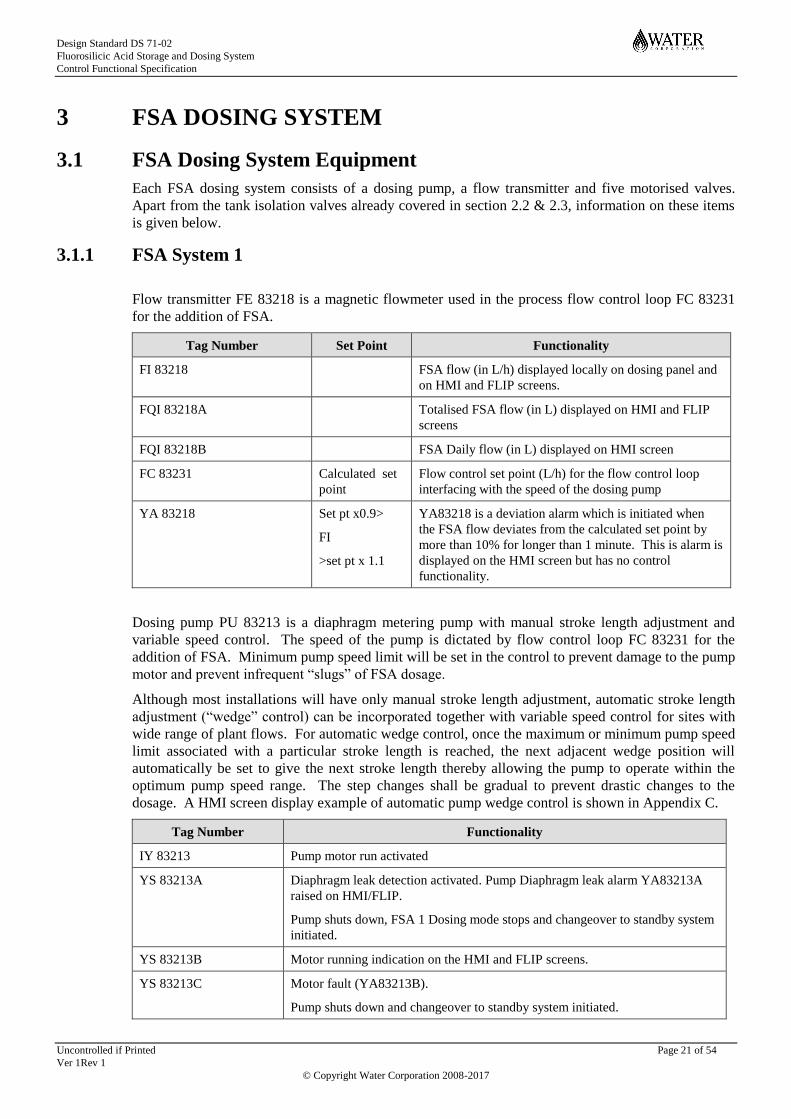
Flow transmitter FE 83218 is a magnetic flowmeter used in the process flow control loop FC 83231
for the addition of FSA.
Tag Number Set Point Functionality
FI 83218 FSA flow (in L/h) displayed locally on dosing panel and
on HMI and FLIP screens.
FQI 83218A Totalised FSA flow (in L) displayed on HMI and FLIP
screens
FQI 83218B FSA Daily flow (in L) displayed on HMI screen
FC 83231 Calculated set
point
Flow control set point (L/h) for the flow control loop
interfacing with the speed of the dosing pump
YA 83218 Set pt x0.9>
FI
>set pt x 1.1
YA83218 is a deviation alarm which is initiated when
the FSA flow deviates from the calculated set point by
more than 10% for longer than 1 minute. This is alarm is
displayed on the HMI screen but has no control
functionality.
Dosing pump PU 83213 is a diaphragm metering pump with manual stroke length adjustment and
variable speed control. The speed of the pump is dictated by flow control loop FC 83231 for the
addition of FSA. Minimum pump speed limit will be set in the control to prevent damage to the pump
motor and prevent infrequent “slugs” of FSA dosage.
Although most installations will have only manual stroke length adjustment, automatic stroke length
adjustment (“wedge” control) can be incorporated together with variable speed control for sites with
wide range of plant flows. For automatic wedge control, once the maximum or minimum pump speed
limit associated with a particular stroke length is reached, the next adjacent wedge position will
automatically be set to give the next stroke length thereby allowing the pump to operate within the
optimum pump speed range. The step changes shall be gradual to prevent drastic changes to the
dosage. A HMI screen display example of automatic pump wedge control is shown in Appendix C.
Tag Number Functionality
IY 83213 Pump motor run activated
YS 83213A Diaphragm leak detection activated. Pump Diaphragm leak alarm YA83213A
raised on HMI/FLIP.
Pump shuts down, FSA 1 Dosing mode stops and changeover to standby system
initiated.
YS 83213B Motor running indication on the HMI and FLIP screens.
YS 83213C Motor fault (YA83213B).
Pump shuts down and changeover to standby system initiated.

Design Standard DS 71-02
Fluorosilicic Acid Storage and Dosing System
Control Functional Specification
Uncontrolled if Printed Page 22 of 54
Ver 1Rev 1
© Copyright Water Corporation 2008-2017
SI 83213 Pump speed indication on the HMI and FLIP screens.
KQT 83213 Number of hours running will be totalised and displayed on the HMI and FLIP
screens
Valve VA 83118 is a three way motorised valve to allow either FSA or flushing (service) water to be
directed to the dosing pump. When the Group Controller is in the AUTO mode, service water can be
directed into the dosing pump suction line if the ‘FSA 1 Flushing Mode’ or ‘FSA 1 Calibration Mode’
operational state is initiated by the Operator from the commands in the sequence controls pop up box
on the FLIP screen.
Tag Number Set Point Functionality
ZSH 83118 Fully open Indication to notify the control system that valve VA 83118 is open
to acid.
ZSL 83118 Fully closed Indication to notify the control system that valve VA 83118 is closed
(open to water).
ZA 83118 Valve fault If VA 83118 fails it can cause shutdown of the FSA 1 dosing system.
Valve VA 83132 is a two way motorised isolation valve to allow flushing (service) water to enter the
flushing circuit via the three way valve VA83118. When the Group Controller is in the AUTO mode,
flushing water can only be activated when the ‘FSA 1 Flushing’ operational state is initiated by the
Operator from the commands in the sequence controls pop up box on the FLIP screen.
Tag Number Set Point Functionality
ZSH 83132 Fully open Indication to notify the control system that valve VA 83132 is open.
ZSL 83132 Fully closed Indication to notify the control system that valve VA 83132 is
closed.
ZA 83132 Valve fault If VA 83132 fails it can cause a shutdown of the dosing system.
Valve VA 83224 is a three way motorised valve to discharge FSA into the process stream or to drain.
The majority of the time this valve will be open to dose. However, when the Group Controller is in
the AUTO mode, FSA can be directed to drain if the ‘FSA 1 Flushing Mode’ is initiated by the
Operator from the commands in the controls pop up box on the FLIP screen and the operator
manually selects the dose/drain valve to drain.
Tag Number Set Point Functionality
ZSH 83224 Fully open Indication to notify the control system that valve VA 83224 is open
to dose.
ZSL 83224 Fully closed Indication to notify the control system that valve VA 83224 is closed
(open to drain).
ZA 83224 Valve fault If VA 83224 fails it can cause shutdown of the dosing system and
changeover to the standby system.
Valve VA 83202 is a two way motorised valve to allow dilution water to enter the dosing panel.
When the Group Controller is in the AUTO mode, valve VA 83202 will open if any of the operational
states, except Manual, are initiated by the Operator from the commands in the sequence controls pop
up box on the FLIP screen.
Design Standard DS 71-02
Fluorosilicic Acid Storage and Dosing System
Control Functional Specification
Uncontrolled if Printed Page 23 of 54
Ver 1Rev 1
© Copyright Water Corporation 2008-2017
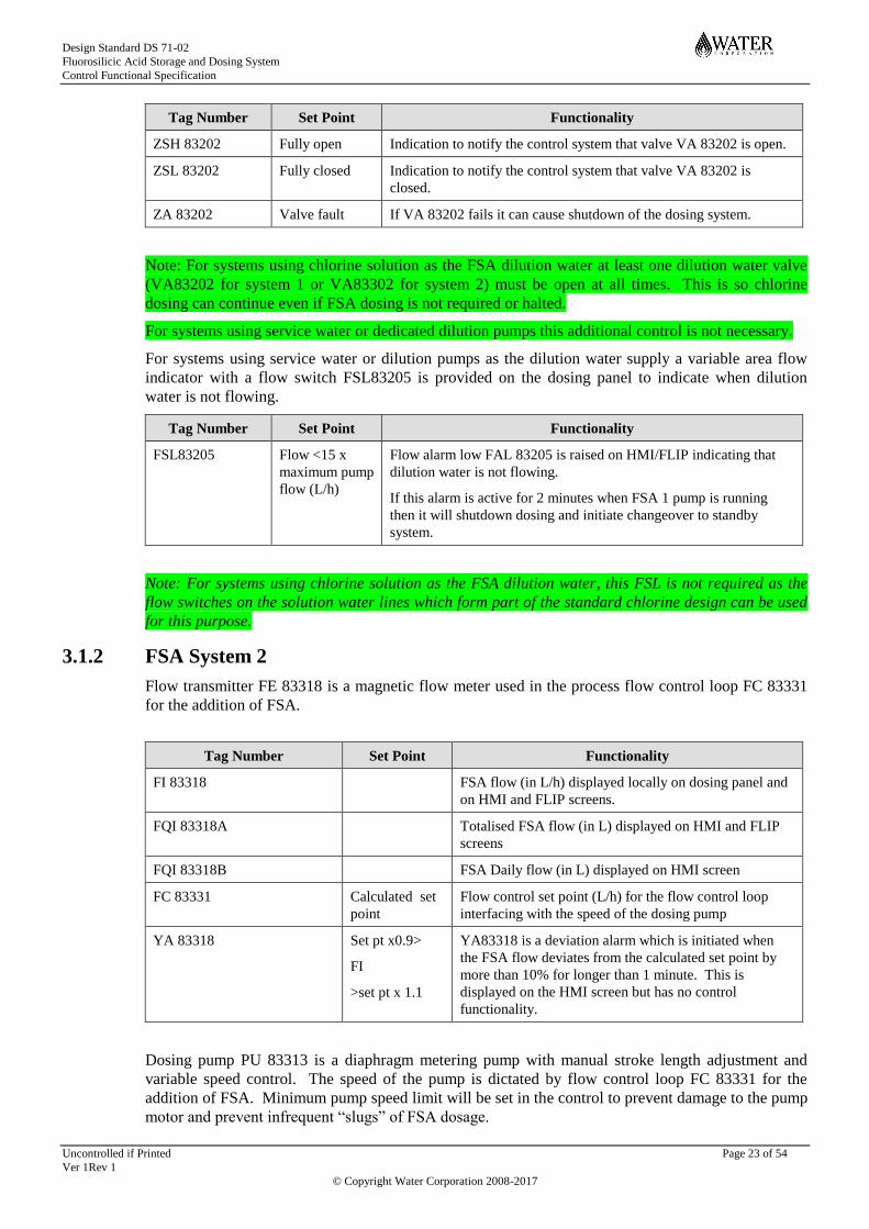
Tag Number Set Point Functionality
ZSH 83202 Fully open Indication to notify the control system that valve VA 83202 is open.
ZSL 83202 Fully closed Indication to notify the control system that valve VA 83202 is
closed.
ZA 83202 Valve fault If VA 83202 fails it can cause shutdown of the dosing system.
Note: For systems using chlorine solution as the FSA dilution water at least one dilution water valve
(VA83202 for system 1 or VA83302 for system 2) must be open at all times. This is so chlorine
dosing can continue even if FSA dosing is not required or halted.
For systems using service water or dedicated dilution pumps this additional control is not necessary.
For systems using service water or dilution pumps as the dilution water supply a variable area flow
indicator with a flow switch FSL83205 is provided on the dosing panel to indicate when dilution
water is not flowing.
Tag Number Set Point Functionality
FSL83205 Flow <15 x
maximum pump
flow (L/h)
Flow alarm low FAL 83205 is raised on HMI/FLIP indicating that
dilution water is not flowing.
If this alarm is active for 2 minutes when FSA 1 pump is running
then it will shutdown dosing and initiate changeover to standby
system.
Note: For systems using chlorine solution as the FSA dilution water, this FSL is not required as the
flow switches on the solution water lines which form part of the standard chlorine design can be used
for this purpose.
3.1.2 FSA System 2
Flow transmitter FE 83318 is a magnetic flow meter used in the process flow control loop FC 83331
for the addition of FSA.
Tag Number Set Point Functionality
FI 83318 FSA flow (in L/h) displayed locally on dosing panel and
on HMI and FLIP screens.
FQI 83318A Totalised FSA flow (in L) displayed on HMI and FLIP
screens
FQI 83318B FSA Daily flow (in L) displayed on HMI screen
FC 83331 Calculated set
point
Flow control set point (L/h) for the flow control loop
interfacing with the speed of the dosing pump
YA 83318 Set pt x0.9>
FI
>set pt x 1.1
YA83318 is a deviation alarm which is initiated when
the FSA flow deviates from the calculated set point by
more than 10% for longer than 1 minute. This is
displayed on the HMI screen but has no control
functionality.
Dosing pump PU 83313 is a diaphragm metering pump with manual stroke length adjustment and
variable speed control. The speed of the pump is dictated by flow control loop FC 83331 for the
addition of FSA. Minimum pump speed limit will be set in the control to prevent damage to the pump
motor and prevent infrequent “slugs” of FSA dosage.
Design Standard DS 71-02
Fluorosilicic Acid Storage and Dosing System
Control Functional Specification
Uncontrolled if Printed Page 24 of 54
Ver 1Rev 1
© Copyright Water Corporation 2008-2017
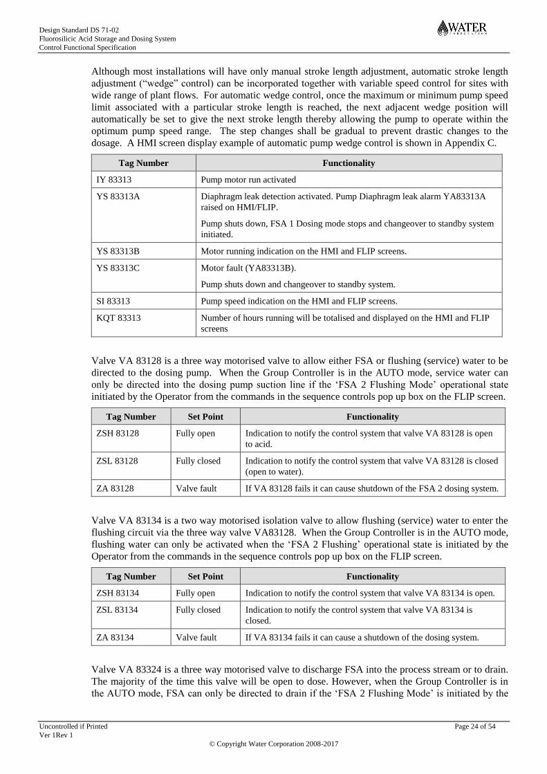
Although most installations will have only manual stroke length adjustment, automatic stroke length
adjustment (“wedge” control) can be incorporated together with variable speed control for sites with
wide range of plant flows. For automatic wedge control, once the maximum or minimum pump speed
limit associated with a particular stroke length is reached, the next adjacent wedge position will
automatically be set to give the next stroke length thereby allowing the pump to operate within the
optimum pump speed range. The step changes shall be gradual to prevent drastic changes to the
dosage. A HMI screen display example of automatic pump wedge control is shown in Appendix C.
Tag Number Functionality
IY 83313 Pump motor run activated
YS 83313A Diaphragm leak detection activated. Pump Diaphragm leak alarm YA83313A
raised on HMI/FLIP.
Pump shuts down, FSA 1 Dosing mode stops and changeover to standby system
initiated.
YS 83313B Motor running indication on the HMI and FLIP screens.
YS 83313C Motor fault (YA83313B).
Pump shuts down and changeover to standby system.
SI 83313 Pump speed indication on the HMI and FLIP screens.
KQT 83313 Number of hours running will be totalised and displayed on the HMI and FLIP
screens
Valve VA 83128 is a three way motorised valve to allow either FSA or flushing (service) water to be
directed to the dosing pump. When the Group Controller is in the AUTO mode, service water can
only be directed into the dosing pump suction line if the ‘FSA 2 Flushing Mode’ operational state
initiated by the Operator from the commands in the sequence controls pop up box on the FLIP screen.
Tag Number Set Point Functionality
ZSH 83128 Fully open Indication to notify the control system that valve VA 83128 is open
to acid.
ZSL 83128 Fully closed Indication to notify the control system that valve VA 83128 is closed
(open to water).
ZA 83128 Valve fault If VA 83128 fails it can cause shutdown of the FSA 2 dosing system.
Valve VA 83134 is a two way motorised isolation valve to allow flushing (service) water to enter the
flushing circuit via the three way valve VA83128. When the Group Controller is in the AUTO mode,
flushing water can only be activated when the ‘FSA 2 Flushing’ operational state is initiated by the
Operator from the commands in the sequence controls pop up box on the FLIP screen.
Tag Number Set Point Functionality
ZSH 83134 Fully open Indication to notify the control system that valve VA 83134 is open.
ZSL 83134 Fully closed Indication to notify the control system that valve VA 83134 is
closed.
ZA 83134 Valve fault If VA 83134 fails it can cause a shutdown of the dosing system.
Valve VA 83324 is a three way motorised valve to discharge FSA into the process stream or to drain.
The majority of the time this valve will be open to dose. However, when the Group Controller is in
the AUTO mode, FSA can only be directed to drain if the ‘FSA 2 Flushing Mode’ is initiated by the

Design Standard DS 71-02
Fluorosilicic Acid Storage and Dosing System
Control Functional Specification
Uncontrolled if Printed Page 25 of 54
Ver 1Rev 1
© Copyright Water Corporation 2008-2017
Operator from the commands in the controls pop up box on the FLIP screen and the operator
manually selects the dose/drain valve to drain.
Tag Number Set Point Functionality
ZSH 83324 Fully open Indication to notify the control system that valve VA 83324 is open
to dose.
ZSL 83324 Fully closed Indication to notify the control system that valve VA 83324 is closed
(open to drain).
ZA 83324 Valve fault If VA 83324 fails it can cause shutdown of the dosing system and
changeover to the standby system.
Valve VA 83302 is a two way motorised valve to allow dilution water to enter the dosing panel.
When the Group Controller is in the AUTO mode, valve VA 83302 will open if any of the operational
states, except Manual, are initiated by the Operator from the commands in the sequence controls pop
up box on the FLIP screen.
Tag Number Set Point Functionality
ZSH 83302 Fully open Indication to notify the control system that valve VA 83302 is open.
ZSL 83302 Fully closed Indication to notify the control system that valve VA 83302 is
closed.
ZA 83302 Valve fault If VA 83302 fails it can cause shutdown of the dosing system and
changeover to the standby system.
Note: For systems using chlorine solution as the FSA dilution water at least one dilution water valve
(VA83202 for system 1 or VA83302 for system 2) must be open at all times. This is so chlorine
dosing can continue even if FSA dosing is not required or halted.
For systems using service water or dedicated dilution pumps this additional interlock is not necessary.
For systems using service water or dilution pumps as the dilution water supply a variable area flow
indicator with a flow switch FSL83305 is provided on the dosing panel to indicate when dilution
water is not flowing.
Tag Number Set Point Functionality
FSL83305 Flow <15 x
maximum pump
flow (L/h)
Flow alarm low FAL 83305 is raised on HMI/FLIP indicating that
dilution water is not flowing.
If this alarm is active for 2 minutes when FSA 2 pump is running
then it will shutdown dosing and initiate changeover to standby
system.
Note: For systems using chlorine solution as the FSA dilution water this FSL is not required as the
flow switches on the solution water lines which form part of the standard chlorine design can be used
for this purpose.

Design Standard DS 71-02
Fluorosilicic Acid Storage and Dosing System
Control Functional Specification
Uncontrolled if Printed Page 26 of 54
Ver 1Rev 1
© Copyright Water Corporation 2008-2017
4 FSA SAMPLING, ANALYSING & MISCELLANEOUS
SYSTEMS
4.1 FSA Sampling & Analysing System Equipment
Each FSA facility will have a sampling and analysing system which consists of at least a fluoride
concentration analyser and a flow switch. Information on these items is given below.
Flow switch FSL 83410 is an inline flow switch used to raise alarm when the flow to the fluoride
analyser is interrupted.
Tag Number Set Point Functionality
FSL83410 <Minimum
fluoride
analyser
requirements>
~ 1 (L/h)
Flow alarm low FAL 83410 is raised on HMI indicating that
sampling water is not flowing.
If this alarm is active for 15 minutes when either dosing system is
running then it will shutdown dosing.
Fluoride analyser AE83411 will continuously monitor the fluoride ion concentration in the recipient
water main (downstream of the dose point).
Tag Number Set Point Functionality
AI 83411 Fluoride concentration in recipient water main (in mg/L) displayed
on HMI and FLIP screens.
AAHH 83411 1.0 mg/L High-high alarm displayed on HMI and FLIP screens to register
unacceptable fluoride in drinking water.
This high-high level has to be registered continuously for a period of
30 seconds before an alarm condition is initiated.
This alarm will shutdown the duty dosing system in operation and
initiates the standby system.
AAH 83411 0.9 mg/L High alarm on HMI and FLIP screens to register unacceptable
fluoride in drinking water.
This high level has to be registered continuously for a period of 30
seconds before an alarm condition is initiated.
There is no control action associated with this alarm condition.
AAL 83411 0.7 mg/L Low alarm on HMI and FLIP screens to register unacceptable
fluoride in drinking water.
This low level has to be registered continuously for a period of 30
seconds before an alarm condition is initiated.
There is no control action associated with this alarm condition.
AALL 83411 0.5 mg/L Low-low alarm on HMI and FLIP screens to register unacceptable
fluoride in drinking water.
This low level has to be registered continuously for a period of 30
seconds before an alarm condition is initiated.
This alarm condition will terminate operation of the duty FSA
dosing system and initiate operation of the standby system.
Design Standard DS 71-02
Fluorosilicic Acid Storage and Dosing System
Control Functional Specification
Uncontrolled if Printed Page 27 of 54
Ver 1Rev 1
© Copyright Water Corporation 2008-2017
4.2 Miscellaneous Equipment – Safety Showers, Hose Reels &
Exhaust Systems
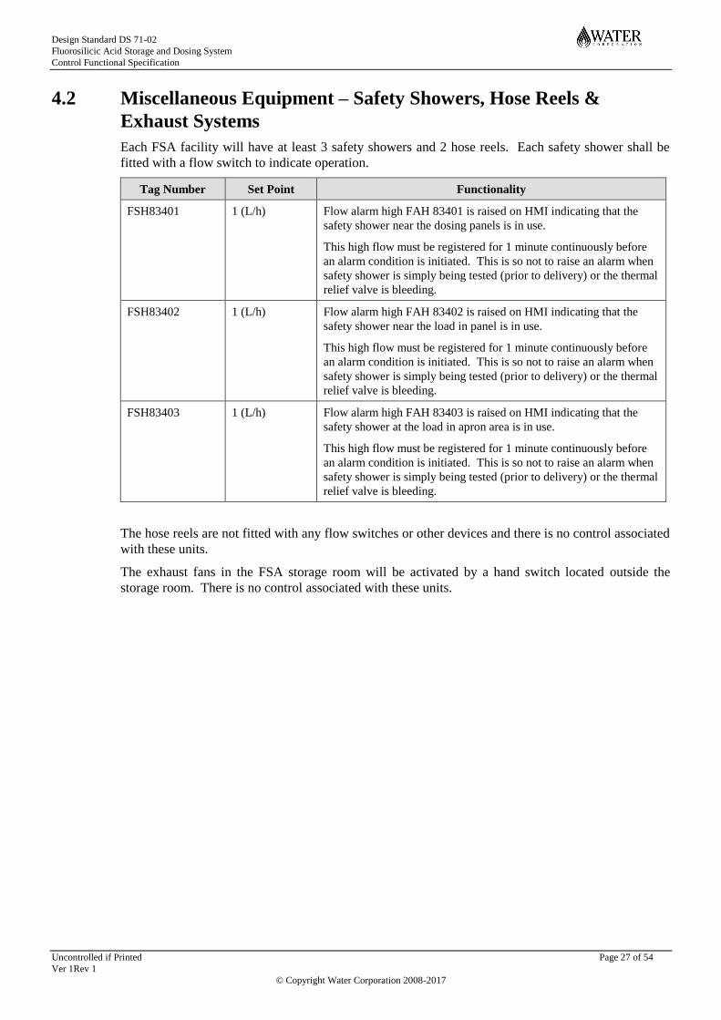
Each FSA facility will have at least 3 safety showers and 2 hose reels. Each safety shower shall be
fitted with a flow switch to indicate operation.
Tag Number Set Point Functionality
FSH83401 1 (L/h) Flow alarm high FAH 83401 is raised on HMI indicating that the
safety shower near the dosing panels is in use.
This high flow must be registered for 1 minute continuously before
an alarm condition is initiated. This is so not to raise an alarm when
safety shower is simply being tested (prior to delivery) or the thermal
relief valve is bleeding.
FSH83402 1 (L/h) Flow alarm high FAH 83402 is raised on HMI indicating that the
safety shower near the load in panel is in use.
This high flow must be registered for 1 minute continuously before
an alarm condition is initiated. This is so not to raise an alarm when
safety shower is simply being tested (prior to delivery) or the thermal
relief valve is bleeding.
FSH83403 1 (L/h) Flow alarm high FAH 83403 is raised on HMI indicating that the
safety shower at the load in apron area is in use.
This high flow must be registered for 1 minute continuously before
an alarm condition is initiated. This is so not to raise an alarm when
safety shower is simply being tested (prior to delivery) or the thermal
relief valve is bleeding.
The hose reels are not fitted with any flow switches or other devices and there is no control associated
with these units.
The exhaust fans in the FSA storage room will be activated by a hand switch located outside the
storage room. There is no control associated with these units.

Design Standard DS 71-02
Fluorosilicic Acid Storage and Dosing System
Control Functional Specification
Uncontrolled if Printed Page 28 of 54
Ver 1Rev 1
© Copyright Water Corporation 2008-2017
5 CONTROL LOOPS AND CALCULATIONS
Control loop FC 83231 associated with the FSA dosing system 1 and FC loop FC 83331 associated
with FSA dosing system 2 are responsible for the introduction of a controlled addition of fluoride ion
into the treated water. The control loop is flow paced from flow transmitter FIT XXXXX located in
the Clearwater recipient pipeline.
The required flow rate (in L/h) from the dosing pumps is given by the following formula,
(Flow rate registered by FIT XXXXX in m3/h) x (Set point fluoride conc in mg/L – Background fluoride conc in mg/L)
7.91 x FSA Delivered conc in % x FSA specific gravity
For example,
If:
FITXXXXX = 5000 m3/h
SP F- conc = 0.85mg/L
Background F- = 0.2mg/L
FSA delivered concentration = 22%
FSA SG (@ 22%) = 1.21
Then: FSA required flow rate = 15.4L/h
The factor of 7.91 relates to the active fluoride ion concentration in FSA. The specific gravity of the
delivered FSA is automatically determined from the look-up table below once the operator has
entered the delivered FSA concentration:
FSA Delivered
Concentration
(w/w)
FSA Specific
Gravity2
20 % 1.19
21 % 1.20
22 % 1.21
23% 1.22
24% 1.23
For system 1, the flow control loop FC 83231 is a direct acting PID loop that maintains the set point
flow through flow transmitter FIT 83218 on the discharge of the dosing pumps. It incorporates a
threshold value of X m3/h whereby the control loop does not exert any control action until the flow
registered by FIT XXXXX exceeds X m3/h.
Similarly for system 2, the flow control loop FC 83331 is a direct acting PID loop that maintains the
set point flow through flow transmitter FIT 83318 on the discharge of the dosing pumps. It
incorporates a threshold value of X m3/h whereby the control loop does not exert any control action
until the flow registered by FIT XXXXX exceeds X m3/h.
The target set point fluoride concentration, background fluoride concentration and delivered acid
concentration can be changed on the HMI and FLIP screens by personnel with designated supervisor
log-on privileges. These set point and other values that are monitored are given below.
2 FSA Specific Gravity is based on samples tested by Wesfarmers CSBP in the last 5 years.

Design Standard DS 71-02
Fluorosilicic Acid Storage and Dosing System
Control Functional Specification
Uncontrolled if Printed Page 29 of 54
Ver 1Rev 1
© Copyright Water Corporation 2008-2017
Tag Number Set Point Functionality
HC 83231A 0.2mg/L* Raw water background fluoride ion concentration (mg/L)
HC 83231B 22%* Delivered Acid Concentration (%)
HC 83231C 0.85 mg/L* Treated water target fluoride concentration for flow control loop FC
83231
FI 83231A Calculated actual fluoride dose rate (mg/L) dispatched into treated
water, displayed on HMI and FLIP screens
FI 83231B PID Controller fluoride dose rate set point (mg/L)
FAHH 83231 1.0 mg/L High-high alarm to register unacceptable fluoride concentration
dispatched into the drinking water distribution system.
The high-high level has to be registered continuously for a period of
5 minutes before an alarm condition is initiated.
This alarm condition will shutdown the duty dosing system in
operation and initiates the standby system.
FAH 83231 0.9 mg/L High alarm to register fluoride concentration above required set
point dispatched into the drinking water.
The high level has to be registered continuously for a period of 5
minutes before an alarm condition is initiated.
There is no control action associated with this alarm condition.
FAL 83231 0.7 mg/L Low alarm to register unacceptable fluoride concentration dispatched
into the drinking water distribution system.
The low level has to be registered continuously for a period of 5
minutes before an alarm condition is initiated.
There is no control action associated with this alarm condition
FALL 83231 0.5 mg/L,
inhibited if
Clearwater flow
FIT XXXXX is
less than X m3/h
(initiating set
point)
Low-low alarm to register unacceptable dosing rate and thereby
potential problems with the duty dosing pump.
The low-low level has to be registered continuously for a period of 5
minutes before an alarm condition is initiated.
This alarm condition will shutdown the duty dosing system in
operation and initiates the standby system.
* denotes setpoint values that can be changed by authorized personnel according to site conditions.
The calculated actual fluoride dose rate FI 83231A is given by the following formula,
Flow rate registered by FIT 83218 (L/h) x 7.91 x FSA Delivered conc in % x FSA specific gravity
Flow rate registered by FIT XXXXX (m3/h)
This value, after adding the raw water background fluoride ion concentration HC 83231A, is used to
initiate alarms FAHH 83231, FAH 83231, FAL 83231 and FALL 83231 when the concentration
strays outside of acceptable limits. The high-high and low-low alarms are also used to shut down the
FSA dosing system completely and initiate changeover to the standby system.
The tag numbers, calculations and set points provided here are for FSA 1 dosing system. The tag
numbers, calculations and set points for FSA 2 dosing system are similar.
Design Standard DS 71-02
Fluorosilicic Acid Storage and Dosing System
Control Functional Specification
Uncontrolled if Printed Page 30 of 54
Ver 1Rev 1
© Copyright Water Corporation 2008-2017
6 PRE-REQUISITES, TRIGGERS & INTERLOCKS FOR
START UP AND FOR SHUTDOWN
6.1 Storage Tank Refilling
There are no pre-requisites or interlocks associated with the tank refilling operation.
The delivery driver is expected to check that he/she is able to deliver the full contents of his tanker
into the tanks prior to unloading by checking the level indication of each tank on the load-in panel and
the maximum full level labels.
The operator observing the delivery is expected to close the manual load-in apron sump isolation
valve VA83138 prior to unloading.
However, these steps are covered by the delivery work instructions and procedures, there are no pre-
requisites, interlocks or controls associated with these functions.
6.2 Bund Sump Discharge
The operation of the bund sump discharge valve VA 83137 is initiated from the FLIP screen.
Interlocks will apply to the valve position if a high conductivity is registered by AIT 83136. When a
high conductivity is registered the following actions will take place,
1 Valve VA 83137 will automatically close if AIT 83136 registers a high conductivity, assuming
that the valve is not closed at the time of the alarm
2 Valve VA 83137 will be prevented from opening if AIT 83136 registers a high conductivity
The operator can override these interlocks by selecting the ‘sump drain override on’ from the FLIP.
However if the valve is left open for longer than 5 minutes continuously then control system will
automatically close the valve whether override is selected or not.
6.3 FSA Dosing System Operational States
The following definitions have been applied,
Pre-requisite Requirements for a sequence to commence
Interlocks Conditions that will prevent an undesirable activation or outcome
Trigger An event when the system is in an operational state that will initiate another
sequence
Abort A sequence resulting from an interlock that will return the system to the
‘FSA Stopped’ state
In the following sub-sections, references are made to FSA system 1 for convenience. FSA system 2
has similar operational states with its associated equipment and instrumentation tag numbers.
The following pre-requisites are required to transition the system from the ‘FSA 1 Stopped’ state to
the ‘FSA 1 Dosing’ state:
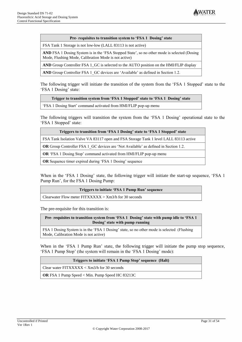
Design Standard DS 71-02
Fluorosilicic Acid Storage and Dosing System
Control Functional Specification
Uncontrolled if Printed Page 31 of 54
Ver 1Rev 1
© Copyright Water Corporation 2008-2017
Pre- requisites to transition system to ‘FSA 1 Dosing’ state
FSA Tank 1 Storage is not low-low (LALL 83113 is not active)
AND FSA 1 Dosing System is in the ‘FSA Stopped State’, so no other mode is selected (Dosing
Mode, Flushing Mode, Calibration Mode is not active)
AND Group Controller FSA 1_GC is selected to the AUTO position on the HMI/FLIP display
AND Group Controller FSA 1_GC devices are ‘Available’ as defined in Section 1.2.
The following trigger will initiate the transition of the system from the ‘FSA 1 Stopped’ state to the
‘FSA 1 Dosing’ state:
Trigger to transition system from ‘FSA 1 Stopped’ state to ‘FSA 1 Dosing’ state
‘FSA 1 Dosing Start’ command activated from HMI/FLIP pop-up menu
The following triggers will transition the system from the ‘FSA 1 Dosing’ operational state to the
‘FSA 1 Stopped’ state:
Triggers to transition from ‘FSA 1 Dosing’ state to ‘FSA 1 Stopped’ state
FSA Tank Isolation Valve VA 83117 open and FSA Storage Tank 1 level LALL 83113 active
OR Group Controller FSA 1_GC devices are ‘Not Available’ as defined in Section 1.2.
OR ‘FSA 1 Dosing Stop’ command activated from HMI/FLIP pop-up menu
OR Sequence timer expired during ‘FSA 1 Dosing’ sequence
When in the ‘FSA 1 Dosing’ state, the following trigger will initiate the start-up sequence, ‘FSA 1
Pump Run’, for the FSA 1 Dosing Pump:
Triggers to initiate ‘FSA 1 Pump Run’ sequence
Clearwater Flow meter FITXXXXX > Xm3/h for 30 seconds
The pre-requisite for this transition is:
Pre- requisites to transition system from ‘FSA 1 Dosing’ state with pump idle to ‘FSA 1
Dosing’ state with pump running
FSA 1 Dosing System is in the ‘FSA 1 Dosing’ state, so no other mode is selected (Flushing
Mode, Calibration Mode is not active)
When in the ‘FSA 1 Pump Run’ state, the following trigger will initiate the pump stop sequence,
‘FSA 1 Pump Stop’ (the system will remain in the ‘FSA 1 Dosing’ mode):
Triggers to initiate ‘FSA 1 Pump Stop’ sequence (Halt)
Clear water FITXXXXX < Xm3/h for 30 seconds
OR FSA 1 Pump Speed < Min. Pump Speed HC 83213C
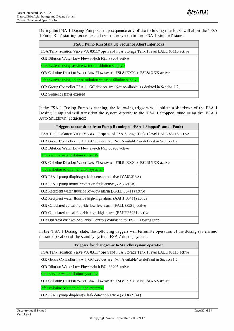
Design Standard DS 71-02
Fluorosilicic Acid Storage and Dosing System
Control Functional Specification
Uncontrolled if Printed Page 32 of 54
Ver 1Rev 1
© Copyright Water Corporation 2008-2017
During the FSA 1 Dosing Pump start up sequence any of the following interlocks will abort the ‘FSA
1 Pump Run’ starting sequence and return the system to the ‘FSA 1 Stopped’ state:
FSA 1 Pump Run Start Up Sequence Abort Interlocks
FSA Tank Isolation Valve VA 83117 open and FSA Storage Tank 1 level LALL 83113 active
OR Dilution Water Low Flow switch FSL 83205 active
<for systems using service water for dilution supply>
OR Chlorine Dilution Water Low Flow switch FSL81XXX or FSL81XXX active
<for systems using chlorine solution water as dilution supply>
OR Group Controller FSA 1_ GC devices are ‘Not Available’ as defined in Section 1.2.
OR Sequence timer expired
If the FSA 1 Dosing Pump is running, the following triggers will initiate a shutdown of the FSA 1
Dosing Pump and will transition the system directly to the ‘FSA 1 Stopped’ state using the ‘FSA 1
Auto Shutdown’ sequence:
Triggers to transition from Pump Running to ‘FSA 1 Stopped’ state (Fault)
FSA Tank Isolation Valve VA 83117 open and FSA Storage Tank 1 level LALL 83113 active
OR Group Controller FSA 1_GC devices are ‘Not Available’ as defined in Section 1.2.
OR Dilution Water Low Flow switch FSL 83205 active
<for service water dilution systems>
OR Chlorine Dilution Water Low Flow switch FSL81XXX or FSL81XXX active
<for chlorine solution dilution systems>
OR FSA 1 pump diaphragm leak detection active (YA83213A)
OR FSA 1 pump motor protection fault active (YA83213B)
OR Recipient water fluoride low-low alarm (AALL 83411) active
OR Recipient water fluoride high-high alarm (AAHH83411) active
OR Calculated actual fluoride low-low alarm (FALL83231) active
OR Calculated actual fluoride high-high alarm (FAHH83231) active
OR Operator changes Sequence Controls command to ‘FSA 1 Dosing Stop’
In the ‘FSA 1 Dosing’ state, the following triggers will terminate operation of the dosing system and
initiate operation of the standby system, FSA 2 dosing system.
Triggers for changeover to Standby system operation
FSA Tank Isolation Valve VA 83117 open and FSA Storage Tank 1 level LALL 83113 active
OR Group Controller FSA 1_GC devices are ‘Not Available’ as defined in Section 1.2.
OR Dilution Water Low Flow switch FSL 83205 active
<for service water dilution systems>
OR Chlorine Dilution Water Low Flow switch FSL81XXX or FSL81XXX active
<for chlorine solution dilution systems>
OR FSA 1 pump diaphragm leak detection active (YA83213A)

Design Standard DS 71-02
Fluorosilicic Acid Storage and Dosing System
Control Functional Specification
Uncontrolled if Printed Page 33 of 54
Ver 1Rev 1
© Copyright Water Corporation 2008-2017
OR FSA 1 pump motor protection fault active (YA83213B)
OR Recipient water fluoride low-low alarm (AALL 83411) active
OR Recipient water fluoride high-high alarm (AAHH83411) active
OR Calculated actual fluoride low-low alarm (FALL83231) active
OR Calculated actual fluoride high-high alarm (FAHH83231) active
OR When FSA 1 Dosing system is transitioned to the ‘FSA 1 Stopped’ state by the control system
executing the ‘FSA 1 Auto shutdown’ sequence (not operator selected).
The prerequisite for this transition to occur is that the FSA 2 dosing system must already have been
placed in the mode ‘FSA 2 Dosing’ by the Operator and selected as the standby system (not selected
as the duty system).
Pre- requisites to Transition from ‘FSA 1 Dosing’ state to ‘FSA 2 Dosing’ state
FSA 2 Dosing System is in the ‘FSA 2 Dosing’ state, so no other mode is selected (Flushing
Mode, Calibration Mode, Manual Mode is not active)
When a dosing system is selected to be in dosing mode, ‘FSA <dosing system number> Dosing’, but
not selected as the duty system then the tank outlet isolation valve (VA83117 or VA83127) and the
dilution water valve (VA83202 or VA83302) will remain closed. It will not open until the standby
system is requested to operate by one of the changeover triggers.
6.4 FSA Flushing Operational State
The following pre-requisites are required for the start-up of the ‘FSA 1 Flushing’ sequence:
The Tank Outlet Valve VA83118 does not need to be available as this is already closed in the ‘FSA
Stopped’ State and is not required to open as part of the flushing sequence.
The trigger to transition the system to the flushing state is:
Triggers to initiate ‘FSA 1 Flushing Start’ Sequence
‘FSA 1 Flushing Start’ command activated on the FLIP Pop up menu
Pre- requisites to transition system to ‘FSA 1 Flushing’ state
Group Controller FSA 1_GC is selected to the AUTO position on the HMI/FLIP display
AND FSA 1 Dosing System is in the ‘FSA Stopped’ operational state, so no other mode
is selected (Dosing Mode, Flushing Mode and Calibration Mode is not active)
AND Acid/Water Selector Valve VA 83118 is ‘Available’
AND Flushing (Service Water) Isolation Valve VA 83132 is ‘Available’
AND Dilution Water Isolation Valve VA 83202 is ‘Available’
AND Dose/Drain Selector Valve VA 83224 is ‘Available’
AND FSA 1 Dosing Pump PU83213 is ‘Available’
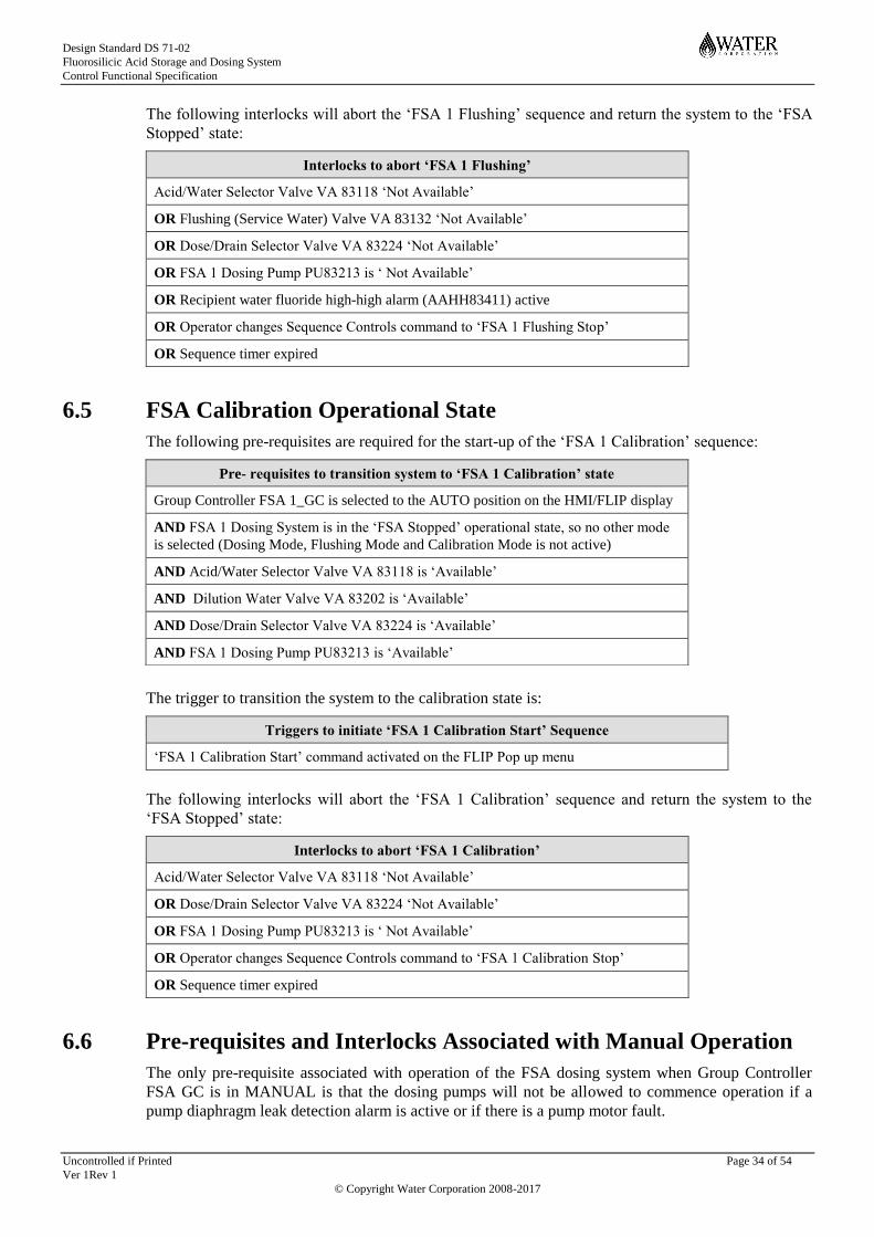
Design Standard DS 71-02
Fluorosilicic Acid Storage and Dosing System
Control Functional Specification
Uncontrolled if Printed Page 34 of 54
Ver 1Rev 1
© Copyright Water Corporation 2008-2017
The following interlocks will abort the ‘FSA 1 Flushing’ sequence and return the system to the ‘FSA
Stopped’ state:
Interlocks to abort ‘FSA 1 Flushing’
Acid/Water Selector Valve VA 83118 ‘Not Available’
OR Flushing (Service Water) Valve VA 83132 ‘Not Available’
OR Dose/Drain Selector Valve VA 83224 ‘Not Available’
OR FSA 1 Dosing Pump PU83213 is ‘ Not Available’
OR Recipient water fluoride high-high alarm (AAHH83411) active
OR Operator changes Sequence Controls command to ‘FSA 1 Flushing Stop’
OR Sequence timer expired
6.5 FSA Calibration Operational State
The following pre-requisites are required for the start-up of the ‘FSA 1 Calibration’ sequence:
The trigger to transition the system to the calibration state is:
Triggers to initiate ‘FSA 1 Calibration Start’ Sequence
‘FSA 1 Calibration Start’ command activated on the FLIP Pop up menu
The following interlocks will abort the ‘FSA 1 Calibration’ sequence and return the system to the
‘FSA Stopped’ state:
Interlocks to abort ‘FSA 1 Calibration’
Acid/Water Selector Valve VA 83118 ‘Not Available’
OR Dose/Drain Selector Valve VA 83224 ‘Not Available’
OR FSA 1 Dosing Pump PU83213 is ‘ Not Available’
OR Operator changes Sequence Controls command to ‘FSA 1 Calibration Stop’
OR Sequence timer expired
6.6 Pre-requisites and Interlocks Associated with Manual Operation
The only pre-requisite associated with operation of the FSA dosing system when Group Controller
FSA GC is in MANUAL is that the dosing pumps will not be allowed to commence operation if a
pump diaphragm leak detection alarm is active or if there is a pump motor fault.
Pre- requisites to transition system to ‘FSA 1 Calibration’ state
Group Controller FSA 1_GC is selected to the AUTO position on the HMI/FLIP display
AND FSA 1 Dosing System is in the ‘FSA Stopped’ operational state, so no other mode
is selected (Dosing Mode, Flushing Mode and Calibration Mode is not active)
AND Acid/Water Selector Valve VA 83118 is ‘Available’
AND Dilution Water Valve VA 83202 is ‘Available’
AND Dose/Drain Selector Valve VA 83224 is ‘Available’
AND FSA 1 Dosing Pump PU83213 is ‘Available’
Design Standard DS 71-02
Fluorosilicic Acid Storage and Dosing System
Control Functional Specification
Uncontrolled if Printed Page 35 of 54
Ver 1Rev 1
© Copyright Water Corporation 2008-2017
An interlock will terminate pump operation if a pump diaphragm leak detection alarm is registered
when the pump is in operation.
Also, in manual mode an interlock will prevent the dose/drain valve, VA83224 or VA83324, being
selected to drain (closed) if the acid/water selector valve, VA83118 or VA83128, is open to acid
(open).
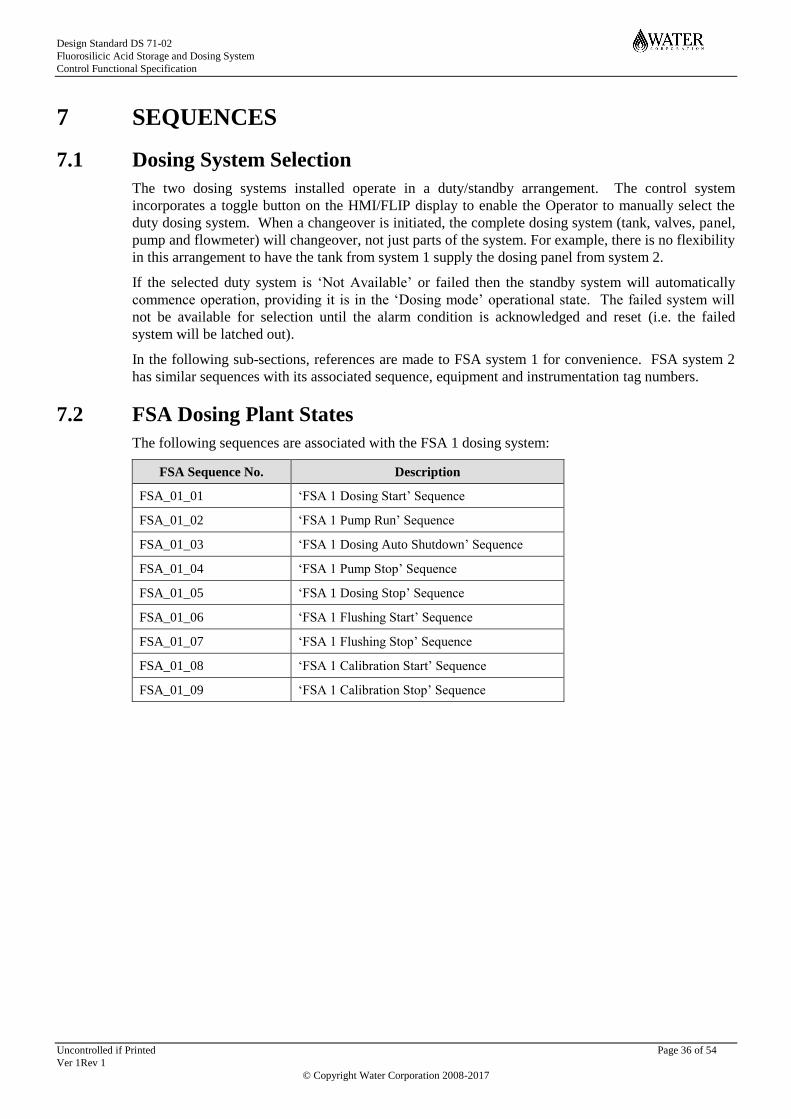
Design Standard DS 71-02
Fluorosilicic Acid Storage and Dosing System
Control Functional Specification
Uncontrolled if Printed Page 36 of 54
Ver 1Rev 1
© Copyright Water Corporation 2008-2017
7 SEQUENCES
7.1 Dosing System Selection
The two dosing systems installed operate in a duty/standby arrangement. The control system
incorporates a toggle button on the HMI/FLIP display to enable the Operator to manually select the
duty dosing system. When a changeover is initiated, the complete dosing system (tank, valves, panel,
pump and flowmeter) will changeover, not just parts of the system. For example, there is no flexibility
in this arrangement to have the tank from system 1 supply the dosing panel from system 2.
If the selected duty system is ‘Not Available’ or failed then the standby system will automatically
commence operation, providing it is in the ‘Dosing mode’ operational state. The failed system will
not be available for selection until the alarm condition is acknowledged and reset (i.e. the failed
system will be latched out).
In the following sub-sections, references are made to FSA system 1 for convenience. FSA system 2
has similar sequences with its associated sequence, equipment and instrumentation tag numbers.
7.2 FSA Dosing Plant States
The following sequences are associated with the FSA 1 dosing system:
FSA Sequence No. Description
FSA_01_01 ‘FSA 1 Dosing Start’ Sequence
FSA_01_02 ‘FSA 1 Pump Run’ Sequence
FSA_01_03 ‘FSA 1 Dosing Auto Shutdown’ Sequence
FSA_01_04 ‘FSA 1 Pump Stop’ Sequence
FSA_01_05 ‘FSA 1 Dosing Stop’ Sequence
FSA_01_06 ‘FSA 1 Flushing Start’ Sequence
FSA_01_07 ‘FSA 1 Flushing Stop’ Sequence
FSA_01_08 ‘FSA 1 Calibration Start’ Sequence
FSA_01_09 ‘FSA 1 Calibration Stop’ Sequence

Design Standard DS 71-02
Fluorosilicic Acid Storage and Dosing System
Control Functional Specification
Uncontrolled if Printed Page 37 of 54
Ver 1Rev 1
© Copyright Water Corporation 2008-2017
The transition and sequence between the operating states is shown schematically in the diagram
below.
FS
A_
01
_0
8
FS
A_
01
_0
3
FS
A_
01
_0
1
FS
A_
01
_0
4
FS
A_
01
_0
5
FSA
Flushing F
SA
_0
1_
09
FS
A_
01
_0
6
Operator Command
‘FSA Calibration Stop’ OR Interlock
initiated during calibration sequence
FS
A_
01
_0
2 Trigger from
Clearwater FIT initiates
‘FSA Pump Run’ sequence
Operator Command
‘FSA Dosing Start’
FSA Pump Running
FSA
Dosing
FSA
Stopped
Operator Command
‘FSA Dosing Stop’ OR
shutdown trigger initiated
when in ‘FSA Dosing’ state
Interlock initiated during Pump Run
Start Up sequence OR shutdown
trigger registered in dosing state
Trigger from
Clearwater FIT OR pump
underspeed initiates ‘FSA
Pump Stop’ sequence
Operator Command
‘FSA Flushing Start’
Operator Command
‘FSA Flushing Stop’ OR Interlock
initiated during flushing sequence
FSA
Calibration
FS
A_
01
_0
7
Operator Command
‘FSA Calibration Start’

Design Standard DS 71-02
Fluorosilicic Acid Storage and Dosing System
Control Functional Specification
Uncontrolled if Printed Page 38 of 54
Ver 1Rev 1
© Copyright Water Corporation 2008-2017
The following valve and equipment states are associated with each sequence.
Device
Tank
Outlet
Valve
Acid/
Water
Valve
Flushing
Water
Valve
Dilution
Water
Valve
Dose/
Drain
Valve
Duty
Pump
Control
Loop
State
VA83117
or
VA83127
VA83118
or
VA83128
VA83132
or
VA83134
VA83202
or
VA83302
VA83224
or
VA83324
PU83213
or
PU83313
FC83231
or
FC83331
Out of Service One or more devices OOS Tagged x
All Stopped Closed x Closed Closed x Off Off
Dosing Start Open Open Closed Open Open Running Auto
Flushing Start Closed Closed Open Open Open
(initially) Running Auto
Calibration Start Closed Closed Closed Open Open Manual Manual
Manual Start x x* x x x* Manual Manual
The symbol (x) refers to the device being in any state (holding their last position). * Interlock in
manual mode prevents the dose/drain valve from selecting to drain (closed) if the acid/water valve is
selected to acid (open).
7.3 FSA Dosing Sequences
When the Operator selects the ‘FSA 1 Dosing Start’ command on the Sequence Control pop up, the
following sequence is executed,
‘FSA 1 Dosing’ Sequence (FSA_01_01)
Step Description Step Action Step
Number
Transition Condition Minimum
Step Time
(sec)
‘FSA 1 Dosing’ system
permissive check listed in
Section 6.3
Wait 10 ‘FSA 1 Dosing’ system
start permissive healthy
Initiate ‘Sequence Delay
Timer’
Set ‘Sequence Delay
Timer’ and run timer
20 Timer = 40 40
Open Tank 1 Isolation Valve
VA 83117
Wait 30 Valve VA83117 limit
switch registers valve in
correct position
5
Open valve VA 83118 to port
FSA from tanks to dosing
pumps
Wait 40 Valve VA 83118 limit
switch registers valve in
correct position
5
Open valve VA 83224 to port
FSA from dosing pumps to
dilution line
Wait 50 Valve VA 83224 limit
switch registers valve in
correct position
5
Close Flushing (service water)
isolation valve VA 83132
Wait 60 Valve VA 83132 limit
switch registers a closed
condition
5
Open Dilution water valve
VA83202
Wait 70 Valve VA 83202 limit
switch registers valve in
correct position
5
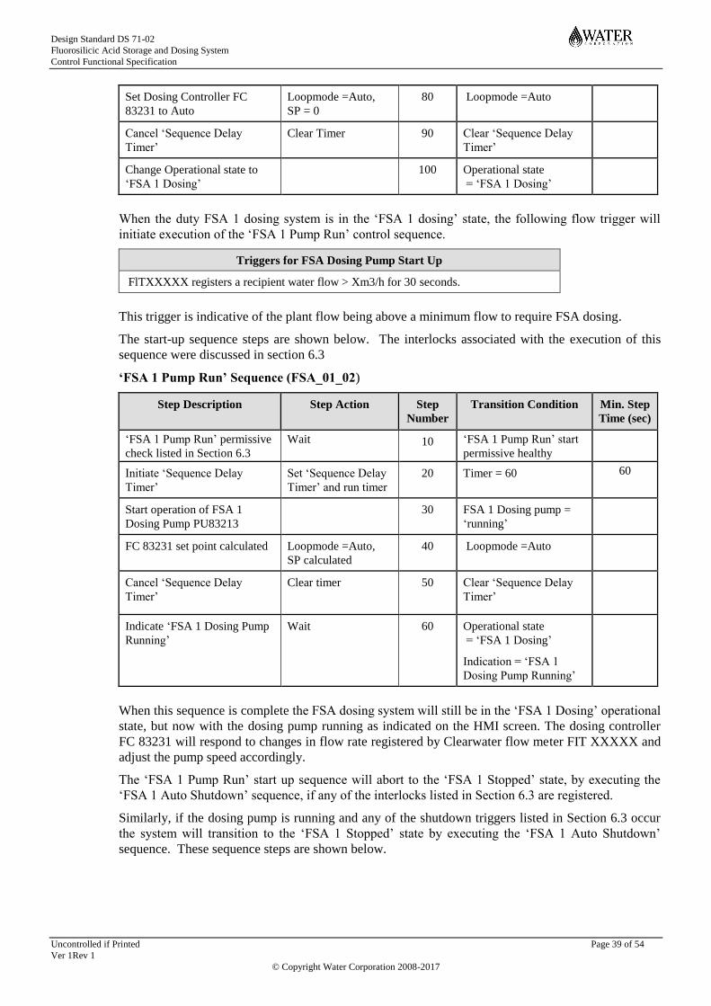
Design Standard DS 71-02
Fluorosilicic Acid Storage and Dosing System
Control Functional Specification
Uncontrolled if Printed Page 39 of 54
Ver 1Rev 1
© Copyright Water Corporation 2008-2017
Set Dosing Controller FC
83231 to Auto
Loopmode =Auto,
SP = 0
80 Loopmode =Auto
Cancel ‘Sequence Delay
Timer’
Clear Timer 90 Clear ‘Sequence Delay
Timer’
Change Operational state to
‘FSA 1 Dosing’
100 Operational state
= ‘FSA 1 Dosing’
When the duty FSA 1 dosing system is in the ‘FSA 1 dosing’ state, the following flow trigger will
initiate execution of the ‘FSA 1 Pump Run’ control sequence.
Triggers for FSA Dosing Pump Start Up
FlTXXXXX registers a recipient water flow > Xm3/h for 30 seconds.
This trigger is indicative of the plant flow being above a minimum flow to require FSA dosing.
The start-up sequence steps are shown below. The interlocks associated with the execution of this
sequence were discussed in section 6.3
‘FSA 1 Pump Run’ Sequence (FSA_01_02)
Step Description Step Action Step
Number
Transition Condition Min. Step
Time (sec)
‘FSA 1 Pump Run’ permissive
check listed in Section 6.3
Wait 10 ‘FSA 1 Pump Run’ start
permissive healthy
Initiate ‘Sequence Delay
Timer’
Set ‘Sequence Delay
Timer’ and run timer
20 Timer = 60 60
Start operation of FSA 1
Dosing Pump PU83213
30 FSA 1 Dosing pump =
‘running’
FC 83231 set point calculated Loopmode =Auto,
SP calculated
40 Loopmode =Auto
Cancel ‘Sequence Delay
Timer’
Clear timer
50 Clear ‘Sequence Delay
Timer’
Indicate ‘FSA 1 Dosing Pump
Running’
Wait 60 Operational state
= ‘FSA 1 Dosing’
Indication = ‘FSA 1
Dosing Pump Running’
When this sequence is complete the FSA dosing system will still be in the ‘FSA 1 Dosing’ operational
state, but now with the dosing pump running as indicated on the HMI screen. The dosing controller
FC 83231 will respond to changes in flow rate registered by Clearwater flow meter FIT XXXXX and
adjust the pump speed accordingly.
The ‘FSA 1 Pump Run’ start up sequence will abort to the ‘FSA 1 Stopped’ state, by executing the
‘FSA 1 Auto Shutdown’ sequence, if any of the interlocks listed in Section 6.3 are registered.
Similarly, if the dosing pump is running and any of the shutdown triggers listed in Section 6.3 occur
the system will transition to the ‘FSA 1 Stopped’ state by executing the ‘FSA 1 Auto Shutdown’
sequence. These sequence steps are shown below.

Design Standard DS 71-02
Fluorosilicic Acid Storage and Dosing System
Control Functional Specification
Uncontrolled if Printed Page 40 of 54
Ver 1Rev 1
© Copyright Water Corporation 2008-2017
‘FSA 1 Auto Shutdown’ Sequence (FSA_01_03)
Step Description Step Action Step
Number
Transition Condition Min. Step
Time (sec)
Stop operation of FSA 1
dosing pump PU83231
10 FSA 1 Dosing pump =
‘not running’
FC 83231 to Off CV = 0 20 Loopmode = Off,
CV = 0
Close FSA Tank 1 Isolation
Valve VA83117
Wait 30 Valve VA83117 limit
switch registers valve in
correct position
5
Close Dilution Water Isolation
valve VA83202
Wait 40 Valve VA83202 limit
switch registers valve in
correct position
5
Change Operational state to
‘FSA 1 Stopped’
Wait 50 Operational state
= ‘FSA 1 Stopped’
The FSA 1 Dosing Pump will stop running, but will remain in the ‘FSA 1 Dosing’ state if the
following flow trigger is registered.
Triggers for FSA Dosing Pump Stop
FlTXXXXX registers a recipient water flow < Xm3/h for 30 seconds.
OR FSA 1 Pump Speed < Min. Pump Speed HC 83213C
The above indicates the requirements of the plant flow to be above a minimum flow before FSA
dosing and the FSA dosing pump to be above a minimum speed to prevent infrequent “slugs” of FSA
and damage to the pump.
The pump stop sequence steps are shown below.
‘FSA 1 Pump Stop’ Sequence (FSA_01_04)
Step Description Step Action Step
Number
Transition Condition Min. Step
Time (sec)
Stop operation of duty dosing
pump
10 Dosing pump = ‘not
running’
FC 83231 set point held at
zero
Loopmode = Auto
SP = 0
20 Loopmode = Auto,
SP = 0
Change Indication to ‘FSA 1
Dosing Pump Stop’
30 Operational state
= ‘FSA 1 Dosing’
Indication = FSA 1
Dosing Pump Stopped
The Operator may terminate operation of the FSA dosing pump, or change the system from the ‘FSA
1 Dosing’ state to the ‘FSA 1 Stopped’ state (whether the pump is running or not) by issuing a ‘FSA 1
Dosing Stop’ command. In this situation the FSA_01_05 sequence will execute and the FSA will
return to the ‘FSA Stopped’ State.
‘FSA 1 Dosing Stop’ Sequence (FSA_01_05)
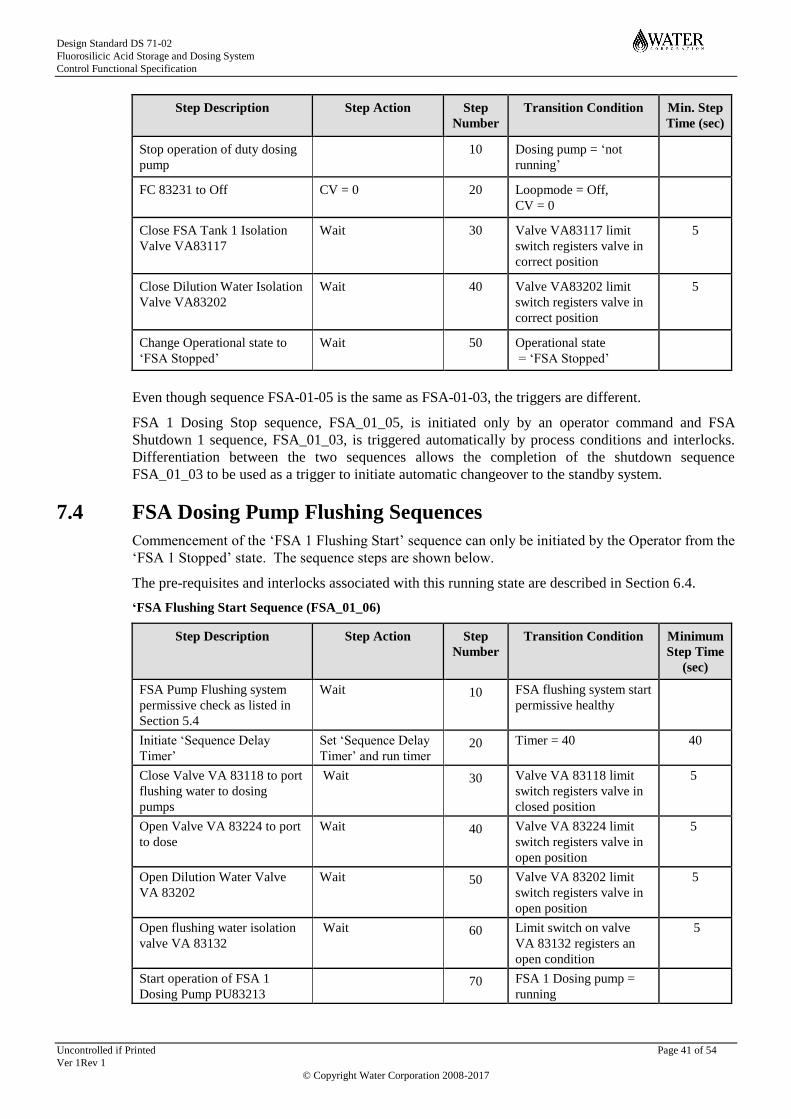
Design Standard DS 71-02
Fluorosilicic Acid Storage and Dosing System
Control Functional Specification
Uncontrolled if Printed Page 41 of 54
Ver 1Rev 1
© Copyright Water Corporation 2008-2017
Step Description Step Action Step
Number
Transition Condition Min. Step
Time (sec)
Stop operation of duty dosing
pump
10 Dosing pump = ‘not
running’
FC 83231 to Off CV = 0 20 Loopmode = Off,
CV = 0
Close FSA Tank 1 Isolation
Valve VA83117
Wait 30 Valve VA83117 limit
switch registers valve in
correct position
5
Close Dilution Water Isolation
Valve VA83202
Wait 40 Valve VA83202 limit
switch registers valve in
correct position
5
Change Operational state to
‘FSA Stopped’
Wait 50 Operational state
= ‘FSA Stopped’
Even though sequence FSA-01-05 is the same as FSA-01-03, the triggers are different.
FSA 1 Dosing Stop sequence, FSA_01_05, is initiated only by an operator command and FSA
Shutdown 1 sequence, FSA_01_03, is triggered automatically by process conditions and interlocks.
Differentiation between the two sequences allows the completion of the shutdown sequence
FSA_01_03 to be used as a trigger to initiate automatic changeover to the standby system.
7.4 FSA Dosing Pump Flushing Sequences
Commencement of the ‘FSA 1 Flushing Start’ sequence can only be initiated by the Operator from the
‘FSA 1 Stopped’ state. The sequence steps are shown below.
The pre-requisites and interlocks associated with this running state are described in Section 6.4.
‘FSA Flushing Start Sequence (FSA_01_06)
Step Description Step Action Step
Number
Transition Condition Minimum
Step Time
(sec)
FSA Pump Flushing system
permissive check as listed in
Section 5.4
Wait 10 FSA flushing system start
permissive healthy
Initiate ‘Sequence Delay
Timer’
Set ‘Sequence Delay
Timer’ and run timer 20 Timer = 40 40
Close Valve VA 83118 to port
flushing water to dosing
pumps
Wait 30 Valve VA 83118 limit
switch registers valve in
closed position
5
Open Valve VA 83224 to port
to dose
Wait 40 Valve VA 83224 limit
switch registers valve in
open position
5
Open Dilution Water Valve
VA 83202
Wait 50 Valve VA 83202 limit
switch registers valve in
open position
5
Open flushing water isolation
valve VA 83132
Wait 60 Limit switch on valve
VA 83132 registers an
open condition
5
Start operation of FSA 1
Dosing Pump PU83213
70 FSA 1 Dosing pump =
running

Design Standard DS 71-02
Fluorosilicic Acid Storage and Dosing System
Control Functional Specification
Uncontrolled if Printed Page 42 of 54
Ver 1Rev 1
© Copyright Water Corporation 2008-2017
FC 83231 set point calculated Loopmode=Auto, SP
calculated 80 Loopmode = Auto
Cancel ‘Sequence Delay
Timer’
Clear timer
90 Clear ‘Sequence Delay
Timer’
Change Operational state to
‘FSA 1 Flushing’
100 Operational state
= ‘FSA 1 Flushing’
Once this sequence has been successfully executed the FSA dosing system will be in the ‘FSA 1
Flushing’ state and the dosing pump will be running with its speed automatically controlled by the
flow controller. The operator is able to manually change the position of the dose/drain valve
VA83224 (via the HMI) to check the pH of the flushing water at the tundish on the dosing panel
(using Litmus paper or a portable pH meter) to determine if flushing needs to continue or can be
stopped. Changing the dose/drain valve position will not stop the flushing sequence.
The system will remain in the ‘FSA 1 flushing’ operational state unless it is terminated by an
interlock (as defined in section 6.4) or an Operator selects the ‘FSA 1 Flushing Stop’ command, in
either of these situations the following sequence will take place,
‘FAS 1 Flushing Stop’ Sequence (FSA_01_07)
Step Description Step Action Step
Number
Transition Condition Minimum
Step Time
(sec)
Stop operation of FSA 1
dosing pump PU83213
10 Dosing pump = ‘not
running’
FC 83231 to Off CV = 0 20 Loopmode = off,
CV = 0
Close flushing water valve VA
83132
Wait 30 Limit switch on valve
VA 83132 registers a
closed condition
5
Close dilution water valve VA
83202
Wait 40 Limit switch on valve
VA 83202 registers a
closed condition
5
Change Operational state to
‘FSA Stopped’
Wait 50 Operational state
= ‘FSA Stopped’
7.5 FSA Dosing Pump Calibration Sequences
Commencement of the ‘FSA 1 Calibration Start’ sequence can only be initiated by the Operator from
the ‘FSA 1 Stopped’ state. The sequence steps are shown below.
The pre-requisites and interlocks associated with this running state are described in Section 6.5.

Design Standard DS 71-02
Fluorosilicic Acid Storage and Dosing System
Control Functional Specification
Uncontrolled if Printed Page 43 of 54
Ver 1Rev 1
© Copyright Water Corporation 2008-2017
‘FSA Calibration Start Sequence (FSA_01_08)
Step Description Step Action Step
Number
Transition Condition Minimum
Step Time
(sec)
FSA Pump Calibration system
permissive check as listed in
Section 5.4
Wait 10 FSA flushing system start
permissive healthy
Initiate ‘Sequence Delay
Timer’
Set ‘Sequence Delay
Timer’ and run timer 20 Timer = 40 40
Close Valve VA 83118 to port
flushing water to dosing
pumps
Wait 30 Valve VA 83118 limit
switch registers valve in
closed position
5
Open Valve VA 83224 to port
to dose
Wait 40 Valve VA 83224 limit
switch registers valve in
open position
5
Open dilution water isolation
valve VA 83202
Wait 50 Limit switch on valve
VA 83202 registers an
open condition
5
Set operation of FSA 1 Dosing
Pump PU83213 to manual
60 FSA 1 Dosing pump =
manual
Set FC 83231 to off Loopmode= Manual 70 Loopmode = Manual
Cancel ‘Sequence Delay
Timer’
Clear timer
80 Clear ‘Sequence Delay
Timer’
Change Operational state to
‘FSA 1 Calibration’
90 Operational state
= ‘FSA 1 Calibration’
Once this sequence has been successfully executed the FSA dosing system will be in the ‘FSA 1
calibration’ state. The dosing pump will be under manual control and the pump speed will be able to
be entered by the operator at the HMI. The pump will not start running until the operator initiates
operation by selecting the “manual start” button on the HMI.
The system will remain in the ‘FSA 1 calibration’ operational state unless it is terminated by an
interlock (as defined in section 6.5) or an Operator selects the ‘FSA 1 calibration Stop’ command, in
either of these situations the following sequence will take place,
‘FAS 1 Calibration Stop’ Sequence (FSA_01_09)
Step Description Step Action Step
Number
Transition Condition Minimum
Step Time
(sec)
Stop operation of FSA 1
dosing pump PU83231
10 Dosing pump = ‘not
running’
FC 83231 to Off CV = 0 20 Loopmode = off,
CV = 0
Close dilution water isolation
valve VA 83202
Wait 30 Limit switch on valve
VA 83202 registers a
closed condition
5
Change Operational state to
‘FSA Stopped’
Wait 40 Operational state
= ‘FSA Stopped’

Design Standard DS 71-02
Fluorosilicic Acid Storage and Dosing System
Control Functional Specification
Uncontrolled if Printed Page 44 of 54
Ver 1Rev 1
© Copyright Water Corporation 2008-2017
8 ALARMS
Alarming is divided into three priority categories:
A ‘Critical’ level alarm is an alarm which will require immediate site operator actions. A
‘Critical’ level alarm will be transferred to telemetry provided RTU COMMS ENABLE is
“on”.
An ‘Urgent’ level alarm will require the operator to address the issue within a limited time
period (less than an hour). An urgent level alarm may also be transferred to telemetry in some
cases.
A ‘Warning’ level alarm is an event logged in the alarm history for review at some appropriate
time.
Critical, Urgent and Warning alarms are indicated on the HMI display in flashing red. Once these
alarms have been accepted the alarm will stop flashing. If an alarm is no longer in an alarmed state,
but has not been acknowledged then it will flash green.
The following alarms are associated with the FSA storage and dosing system:
Instrument
Tag Number
Alarm Message Delay Control System
Action
Alarm
Status
LSHH83110 LAHH 83110 FSA Storage Tank
TA 83110 High-high level
10 seconds Activates high-high
level light and siren
on load-in panel
Critical
LT 83113 LAL 83113 FSA Storage Tank
TA 83110 Low level – re-order
chemical
10 seconds None Warning
LALL 83113 FSA Storage Tank
TA 83110 Low-low level
10 seconds Terminates operation
of FSA 1 dosing
mode if VA 83117 is
open
Critical
LAH 83113 FSA Storage Tank
TA 83110 High level
10 seconds Activates high level
light on load-in panel
Urgent
LSHH83120 LAHH 83120 FSA Storage Tank
TA 83120 High-high level
10 seconds Activates high-high
level light and siren
on load-in panel
Critical
LT 83123 LAL 83123 FSA Storage Tank
TA 83120 Low level – re-order
chemical
10 seconds None Warning
LALL 83123 FSA Storage Tank
TA 83120 Low-low level
10 seconds Terminates operation
of FSA 2 dosing
mode if VA 83127 is
open
Critical
LAH 83123 FSA Storage Tank
TA 83120 High level
10 seconds Activates high level
light on load-in panel
Urgent
VA 83117 ZA 83117 Tank 1 outlet valve VA
83117 fault
10 seconds Aborts mode start up
sequences.
Warning
VA 83117 Tank 1 outlet valve VA
83117 ‘Not Available’
10 seconds Pre-requisite for
start-up as part of
group equipment
availability
Warning

Design Standard DS 71-02
Fluorosilicic Acid Storage and Dosing System
Control Functional Specification
Uncontrolled if Printed Page 45 of 54
Ver 1Rev 1
© Copyright Water Corporation 2008-2017
Instrument
Tag Number
Alarm Message Delay Control System
Action
Alarm
Status
VA 83127 ZA 83127 Tank 2 outlet valve VA
83127 fault
10 seconds Aborts mode start up
sequences.
Warning
VA 83127 Tank 1 outlet valve VA
83127 ‘Not Available’
10 seconds Pre-requisite for
start-up as part of
group equipment
availability
Warning
VA 83118 ZA 83118 Acid/Water selector
valve VA 83118 fault
10 seconds Aborts mode start up
sequences.
Warning
VA 83118 Acid/Water selector
valve VA83118 ‘Not Available’
10 seconds Pre-requisite for
start-up as part of
group equipment
availability
Warning
VA 83128 ZA 83128 Acid/Water selector
valve VA 83128 fault
10 seconds Aborts mode start up
sequences.
Warning
VA 83128 Acid/Water selector
valve VA83128 ‘Not Available’
10 seconds Pre-requisite for
start-up as part of
group equipment
availability
Warning
VA 83132 ZA 83132 Flushing water valve
VA 83132 fault
10 seconds Aborts mode start up
sequences.
Warning
VA 83132 Flushing water valve
VA83132 ‘Not Available’
10 seconds Pre-requisite for
start-up as part of
group equipment
availability
Warning
VA 83134 ZA 83134 Flushing water valve
VA 83134 fault
10 seconds Aborts mode start up
sequences.
Warning
VA 83134 Flushing water valve
VA83134 ‘Not Available’
10 seconds Pre-requisite for
start-up as part of
group equipment
availability
Warning
LSH 83135 LAH 83135 Bund water high level 10 seconds None - if only alarm.
Initiates tank
isolation valves
closure if it occurs in
conjunction with
AAH 83136
Urgent
AE 83136 AAHH 83136 Bund water high-
high conductivity
10 seconds None Critical
AAH 83136 Bund water high
conductivity
10 seconds Interlock to prevent
Valve VA 83137
opening.
Initiates tank
isolation valves
closure if it occurs in
conjunction with
LSH 83135
Urgent
LSH83144 LAH83144 Waste Holding Tank
High Level
10 seconds None Warning

Design Standard DS 71-02
Fluorosilicic Acid Storage and Dosing System
Control Functional Specification
Uncontrolled if Printed Page 46 of 54
Ver 1Rev 1
© Copyright Water Corporation 2008-2017
Instrument
Tag Number
Alarm Message Delay Control System
Action
Alarm
Status
VA 83137 ZA 83137 Drain sump valve VA
83102 fault
10 seconds None Warning
VA 83137 Drain sump valve VA
83137 ‘Not Available’
10 seconds None Warning
VA 83202 ZA 83202 Dilution water valve
VA 83202 fault
10 seconds Aborts mode start up
sequences.
Warning
VA 83202 Dilution water valve
VA 83202 ‘Not Available’
10 seconds Pre-requisite for
start-up as part of
group equipment
availability
Warning
VA 83302 ZA 83302 Dilution water valve
VA 83302 fault
10 seconds Aborts mode start up
sequences.
Warning
VA 83302 Dilution water valve
VA 83302 ‘Not Available’
10 seconds Pre-requisite for
start-up as part of
group equipment
availability
Warning
VA 83224 ZA 83228 Dose/drain valve VA
83224 fault
10 seconds Aborts mode start up
sequences.
Warning
VA 83224 Discharge valve VA
83224 ‘Not Available’
10 seconds Pre-requisite for
start-up as part of
group equipment
availability
Warning
VA 83324 ZA 83324 Dose/drain valve VA
83324 fault
10 seconds Aborts mode start up
sequences.
Warning
VA 83324 Discharge valve VA
83324 ‘Not Available’
10 seconds Pre-requisite for
start-up as part of
group equipment
availability
Warning
PU 83213 YA 83213A Dosing Pump PU
83213 Diaphragm leak detection
active
2 seconds Terminates dosing
system operation and
initiates operation of
standby system, if
available
Urgent
YA 83213B Dosing Pump PU
83213 motor fault
2 seconds Terminates dosing
system operation and
initiates operation of
standby system, if
available
Urgent
PU 83313 YA 83313A Dosing Pump PU
83313 Diaphragm leak detection
active
2 seconds Terminates dosing
system operation and
initiates operation of
standby system, if
available
Urgent
YA 83313B Dosing Pump PU
83313 motor fault
2 seconds Terminates dosing
system operation and
initiates operation of
standby system, if
available
Urgent

Design Standard DS 71-02
Fluorosilicic Acid Storage and Dosing System
Control Functional Specification
Uncontrolled if Printed Page 47 of 54
Ver 1Rev 1
© Copyright Water Corporation 2008-2017
Instrument
Tag Number
Alarm Message Delay Control System
Action
Alarm
Status
FE83218 YA83218 Flow meter deviation
flow alarm
60 seconds None Critical
FE83318 YA83318 Flow meter deviation
flow alarm
60 seconds None Critical
FC 83231 FAHH 83231 Fluoride Dose Rate
High-high
5 minutes Shuts down dosing
and initiates standby
system if available.
Critical
FAH 83231 Fluoride Dose Rate
High
5 minutes None Urgent
FAL 83231 Fluoride Dose Rate
Low
5 minutes None Urgent
FALL 83231 Fluoride Dose Rate
Low-low
5 minutes Shuts down dosing
and initiates standby
system if available.
Critical
FC 83331 FAHH 83331 Fluoride Dose Rate
High-high
5 minutes Shuts down dosing
and initiates standby
system if available.
Critical
FAH 83331 Fluoride Dose Rate
High
5 minutes None Urgent
FAL 83331 Fluoride Dose Rate
Low
5 minutes None Urgent
FALL 83331 Fluoride Dose Rate
Low-low
5 minutes Shuts down dosing
and initiates standby
system if available.
Critical
FSL 83205 FAL 83205 FSA 1 Dilution Water
Low Flow
2 minutes Shuts down dosing
and initiates standby
system if available.
Warning
FSL 83305 FAL 83305 FSA 2 Dilution Water
Low Flow
2 minutes Shuts down dosing
and initiates standby
system if available.
Warning
FSH 83401 FAH 83401 Shower in Use 60 seconds None Warning
FSH 83402 FAH 83402 Shower in Use 60 seconds None Warning
FSH 83403 FAH 83403 Shower in Use 60 seconds None Warning
FSL 83410 FAL 83410 Sample Flow-low 15 minutes Shutdown dosing
systems
Critical
AE 83411 AALL 83411 Fluoride Level
Low-low
30 seconds Shuts down dosing
and initiates standby
system if available.
Critical
AAL 83411 Fluoride Level Low 30 seconds None Warning
AAH 83411 Fluoride Level High 30 seconds None Warning
AAHH 83411 Fluoride Level
High-high
30 seconds Shuts down dosing
and initiates standby
system if available.
Critical

Design Standard DS 71-02
Fluorosilicic Acid Storage and Dosing System
Control Functional Specification
Uncontrolled if Printed Page 48 of 54
Ver 1Rev 1
© Copyright Water Corporation 2008-2017
9 TRENDS
The following trends will be recorded on the HMI system
Instrument Tag
Number
Information Data sampling interval
LT 83113 FSA Storage Tank TA 83110 level 10 seconds
LT 83123 FSA Storage Tank TA 83120 level 10 seconds
FIT 83218 FSA 1 dosing Rate 10 seconds
FIT 83318 FSA 2 dosing Rate 10 seconds
AE 83136 Bund water conductivity 10 seconds
FI 83231 FSA 1 Dosing concentration 10 seconds
FI 83331 FSA 2 Dosing concentration 10 seconds
AI83411 Fluoride Concentration 10 seconds
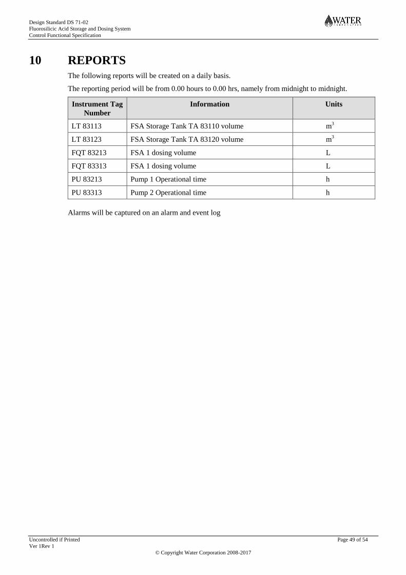
Design Standard DS 71-02
Fluorosilicic Acid Storage and Dosing System
Control Functional Specification
Uncontrolled if Printed Page 49 of 54
Ver 1Rev 1
© Copyright Water Corporation 2008-2017
10 REPORTS
The following reports will be created on a daily basis.
The reporting period will be from 0.00 hours to 0.00 hrs, namely from midnight to midnight.
Instrument Tag
Number
Information Units
LT 83113 FSA Storage Tank TA 83110 volume m3
LT 83123 FSA Storage Tank TA 83120 volume m3
FQT 83213 FSA 1 dosing volume L
FQT 83313 FSA 1 dosing volume L
PU 83213 Pump 1 Operational time h
PU 83313 Pump 2 Operational time h
Alarms will be captured on an alarm and event log

Design Standard DS 71-02
Fluorosilicic Acid Storage and Dosing System
Control Functional Specification
Uncontrolled if Printed Page 50 of 54
Ver 1Rev 1
© Copyright Water Corporation 2008-2017
11 APPENDIX A: STORAGE TANK LEVEL SET POINTS
CALCULATION
This appendix provides some guidance on determining the storage tank level set points.
High-high Level Alarm Set Point (LAHH)
The high-high level alarm should be set at a level which corresponds to 20 seconds before tank
overflow.
The following formulae should be used to calculate this level:
minuteper litresin tank of rate Fill =
metresin bottom tank above levelinvert overflow tank ofHeight =
metresin tank ofdiameter Inside =
metersin bottom tank above alarmhigh high ofHeight
where
250
33.0250 =
2
2
f
o
hha
fo
hha
Q
H
D
H
D
QHDH
This level can be converted to a percentage by calculating Hhha / H0 x 100.
High Level Alarm Set Point (LAH)
The high level alarm should be initiated at a level which corresponds to 1 minute before tank
overflow during the filling operation.
The following formulae should be used to calculate this level :
minuteper litresin tank of rate Fill =
metresin bottom tank above levelinvert overflow tank ofHeight =
metresin tank ofdiameter Inside =
metresin bottom tank above alarmhigh ofHeight =
where
250
250 =
2
2
f
o
ha
fo
ha
Q
H
D
H
D
QHDH
This level can be converted to a percentage by calculating Hha / H0 x 100.
Low Level Alarm (LAL)
The low level alarm or re-order alarm should be triggered at a level which corresponds to the tank
being sufficiently empty to receive a full load of FSA at the end of the delivery turnaround period.
For most metro sites the delivery turnaround is 24 hours, so at this level there should be at least one
day’s supply of acid remaining in the tank.
Low-low Level Alarm (LALL)
The low-low level alarm is essentially to protect the pump from running dry, so its set point should be
just above the invert level of the outlet to prevent air from being entrained in the pump suction line
and pump. 3 minutes of dosing at the maximum flow should be adequate.

Design Standard DS 71-02
Fluorosilicic Acid Storage and Dosing System
Control Functional Specification
Uncontrolled if Printed Page 51 of 54
Ver 1Rev 1
© Copyright Water Corporation 2008-2017
The following formulae can be used to calculate this level:
minuteper litresin rate pump dosingFSA Maximum
metersin bottom tank above leveloutlet process tank ofHeight
metresin tank ofdiameter Inside =
metersin bottom tank above alarm low ofHeight
where
250
3250 =
2
2
m
i
la
mila
Q
H
D
H
D
QHDH
This level can be converted to a percentage by calculating Hla / H0 x 100.

Design Standard DS 71-02
Fluorosilicic Acid Storage and Dosing System
Control Functional Specification
Uncontrolled if Printed Page 52 of 54
Ver 1Rev 1
© Copyright Water Corporation 2008-2017
12 APPENDIX B: FUNCTIONAL DESCRIPTION
OVERVIEW
The controls and interlocks of the Fluorosilicic Acid Storage and Dosing System are summarised in
the Functional Description Overview provided in this Appendix.
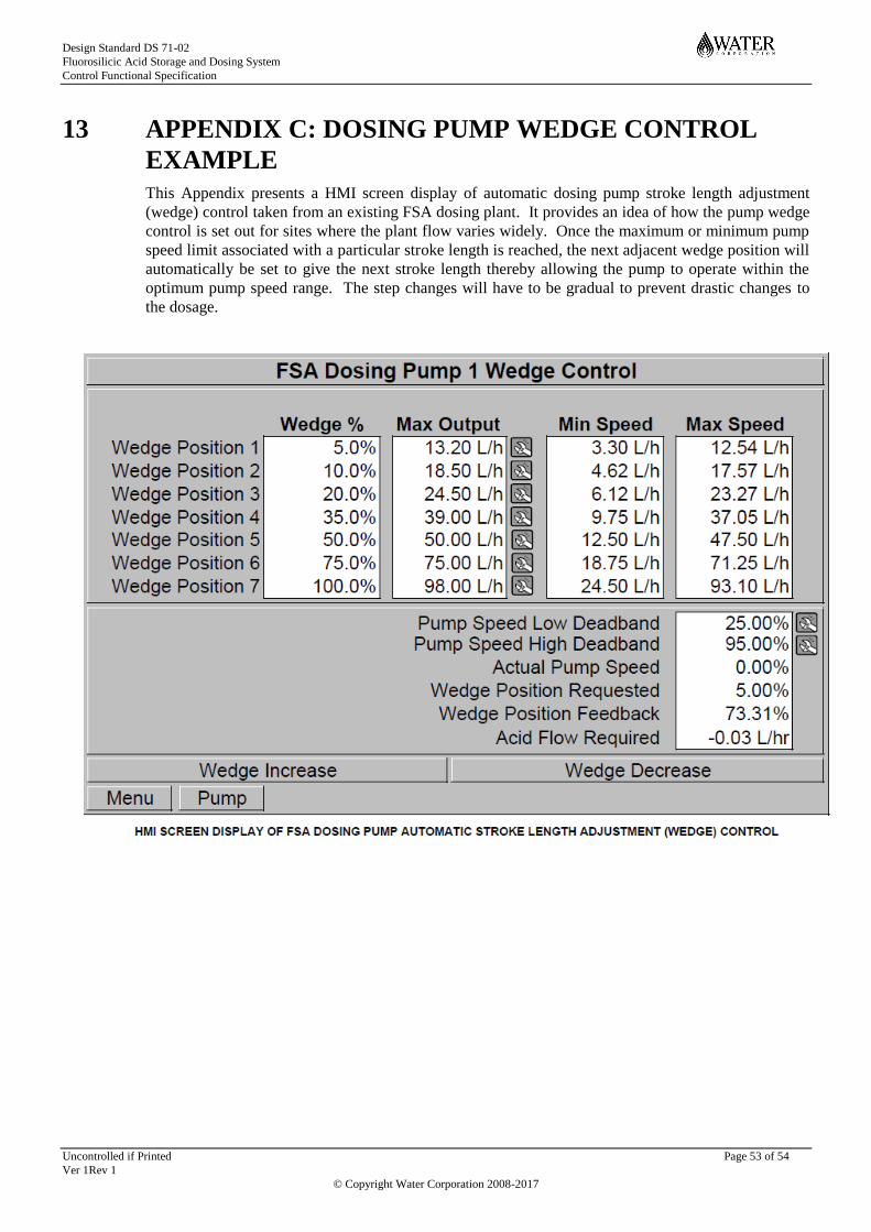
Design Standard DS 71-02
Fluorosilicic Acid Storage and Dosing System
Control Functional Specification
Uncontrolled if Printed Page 53 of 54
Ver 1Rev 1
© Copyright Water Corporation 2008-2017
13 APPENDIX C: DOSING PUMP WEDGE CONTROL
EXAMPLE
This Appendix presents a HMI screen display of automatic dosing pump stroke length adjustment
(wedge) control taken from an existing FSA dosing plant. It provides an idea of how the pump wedge
control is set out for sites where the plant flow varies widely. Once the maximum or minimum pump
speed limit associated with a particular stroke length is reached, the next adjacent wedge position will
automatically be set to give the next stroke length thereby allowing the pump to operate within the
optimum pump speed range. The step changes will have to be gradual to prevent drastic changes to
the dosage.

Design Standard DS 71-02
Fluorosilicic Acid Storage and Dosing System
Control Functional Specification
Uncontrolled if Printed Page 52 of 54
Ver 1Rev 1
© Copyright Water Corporation 2008-2017
END OF DOCUMENT