Design, Simulation, and Fabrication of Thermal … Simulation, and Fabrication of Thermal Angular...
3
Design, Simulation, and Fabrication of Thermal Angular Accelerometers H. Alrowais 1 1 School of Electrical and Computer Engineering, Georgia Institute of Technology, Atlanta, GA, USA Abstract This abstract introduces a sensor design for detecting angular acceleration in a single plane using thermal convection. The working principal of the device is based on probing temperature profile changes along a micro-torus caused by angular acceleration. By properly choosing the locations of the heaters as well as the temperature sensors, the output signal will correlate to in-plane angular acceleration of the micro-structure, while canceling out linear acceleration within the plane. This work demonstrates simulation and experimental results, which provide design guidelines for optimizing the detection of angular acceleration. Measured devices show a sensitivity of 16.1µV/rad/s^2, and a frequency response of DC to 80Hz, while consuming a non- optimized 1.2mW. The design comprises four or more linear thermal accelerometers that are placed along the circumference of a micro-machined torus to detect the tangential acceleration along the torus. The tangential acceleration relates to the angular acceleration though α = a/R, where α, a, and R are the angular acceleration, tangential acceleration, and major radius of the torus, respectively. Each of the four linear accelerometers consists of a central heating resistor and two symmetrically-arranged, resistive temperature probes that monitor the temperature profile generated by the heater. A clockwise angular acceleration applied to the structure increases the temperature of the four upstream probes while the four downstream probes experience a temperature decrease. Thus, the resulting temperature difference is a measure of the applied (tangential) acceleration. An angular acceleration yields the same output for all four sensors, while linear accelerations can be distinguished by their characteristic response patterns. In addition, a closed torus structure (similar to the semicircular canals of the vestibular system) is intrinsically insensitive to linear accelerations. The geometry of the individual sensors, e.g., the distance between heater and T-probe, was optimized using COMSOL Multiphysics® software. Figure 1 shows an optical image of a fabricated angular accelerometer design with R=2.85mm. Figure 2 shows the response of a single sensor to angular acceleration; the particular design had an etched channel depth of 350µm and a main radius R = 2500µm. A rate table was used to apply different angular accelerations with a frequency of 2Hz. The measured device sensitivity is 16.1 µV/rad/s2. COMSOL Multiphysics was used to simulate the device using the Conjugate Heat Transfer
Transcript of Design, Simulation, and Fabrication of Thermal … Simulation, and Fabrication of Thermal Angular...

Design, Simulation, and Fabrication of ThermalAngular Accelerometers
H. Alrowais1
1School of Electrical and Computer Engineering, Georgia Institute of Technology, Atlanta, GA,USA
Abstract
This abstract introduces a sensor design for detecting angular acceleration in a single plane usingthermal convection. The working principal of the device is based on probing temperature profilechanges along a micro-torus caused by angular acceleration. By properly choosing the locationsof the heaters as well as the temperature sensors, the output signal will correlate to in-planeangular acceleration of the micro-structure, while canceling out linear acceleration within theplane. This work demonstrates simulation and experimental results, which provide designguidelines for optimizing the detection of angular acceleration. Measured devices show asensitivity of 16.1µV/rad/s^2, and a frequency response of DC to 80Hz, while consuming a non-optimized 1.2mW.
The design comprises four or more linear thermal accelerometers that are placed along thecircumference of a micro-machined torus to detect the tangential acceleration along the torus.The tangential acceleration relates to the angular acceleration though α = a/R, where α, a, and Rare the angular acceleration, tangential acceleration, and major radius of the torus, respectively.Each of the four linear accelerometers consists of a central heating resistor and twosymmetrically-arranged, resistive temperature probes that monitor the temperature profilegenerated by the heater. A clockwise angular acceleration applied to the structure increases thetemperature of the four upstream probes while the four downstream probes experience atemperature decrease. Thus, the resulting temperature difference is a measure of the applied(tangential) acceleration. An angular acceleration yields the same output for all four sensors,while linear accelerations can be distinguished by their characteristic response patterns. Inaddition, a closed torus structure (similar to the semicircular canals of the vestibular system) isintrinsically insensitive to linear accelerations. The geometry of the individual sensors, e.g., thedistance between heater and T-probe, was optimized using COMSOL Multiphysics® software.
Figure 1 shows an optical image of a fabricated angular accelerometer design with R=2.85mm.Figure 2 shows the response of a single sensor to angular acceleration; the particular design hadan etched channel depth of 350µm and a main radius R = 2500µm. A rate table was used to applydifferent angular accelerations with a frequency of 2Hz. The measured device sensitivity is 16.1µV/rad/s2.
COMSOL Multiphysics was used to simulate the device using the Conjugate Heat Transfer

physics interface. Initial device simulations were performed on a 3D linear structure: to this end,the torus was unwrapped and turned into a linear pipe, with periodic boundary conditions for fluidflow and heat transport being applied to the ends of the device, as shown in Figure 3.Subsequently, a comprehensive 3D torus model was simulated. Fig. 4 shows the temperaturedistribution in the center of the pipe around the heating element for the cases of zero appliedangular acceleration and α = 1000 deg/s2. From the difference of both temperature profiles, theoptimal distance between heater and T-probe can be deduced.
Reference
1. N. Yazdi, F. Ayazi, and K. Najafi, “Micromachined Inertial Sensors,” Proceedings of theIEEE, vol. 86, (1998), pp. 1640–1659.
2. J. Groenesteijn et al., "An Angular Acceleration Sensor Inspired by the Vestibular System witha Fully Circular Fluid-channel and Thermal Read-out," in IEEE International Conference onMicro Electro Mechanical Systems, (2014), pp.696-699.
Figures used in the abstract
Figure 1: Optical image of fabricated device with R=2.85mm. The inset shows a second designwith only two heaters and four temperature sensors.
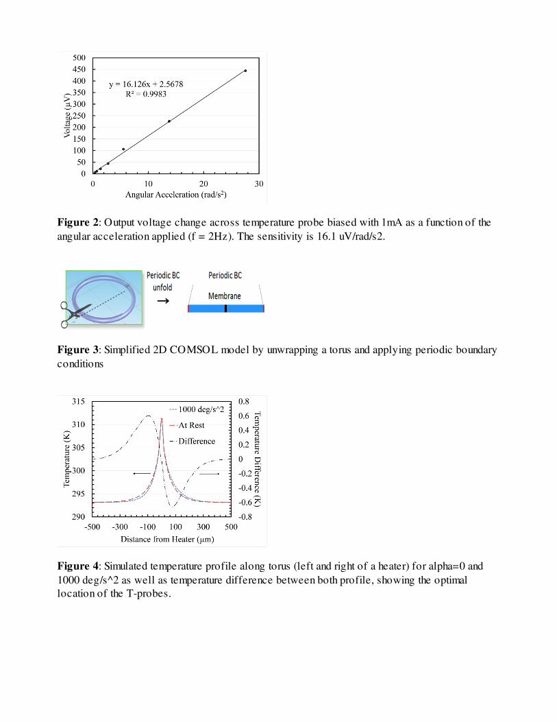
Figure 2: Output voltage change across temperature probe biased with 1mA as a function of theangular acceleration applied (f = 2Hz). The sensitivity is 16.1 uV/rad/s2.
Figure 3: Simplified 2D COMSOL model by unwrapping a torus and applying periodic boundaryconditions
Figure 4: Simulated temperature profile along torus (left and right of a heater) for alpha=0 and1000 deg/s^2 as well as temperature difference between both profile, showing the optimallocation of the T-probes.